1
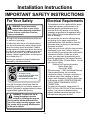
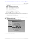
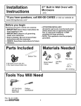
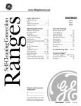
Installation
Instructions
GE Self Cleaning Radiant
Electric Drop-In Range
JDP46,JD966
“If you have questions, call 800-GE-CARES or visit our website at:
www.GEAppliances.com”
Skill Level: High
Average
Low
Completion Time: 1 to 3 Hours
Proper installation is the responsibility of the installer. Product failure due to improper installation
is not covered under the GE Appliance Warranty. See the Owners Manual for warranty
information.
CAUTION: Before you begin
Read these instructions carefully and
completely
• IMPORTANT-Save these instructions for
local inspector’s use.
• IMPORTANT-Observe all governing codes
and ordinances.
Materials Needed
Wire Nuts
(Not smaller than #8
gage combined with
house wiring gage.)
(See warning Page
6 if house wiring is
aluminum.)
• NOTE TO INSTALLER- Be sure to leave
these instructions with the consumer.
• OWNER- Keep these instructions for future
reference.
• WARNING- This appliance must be
properly grounded. See “Electrical
Requirements” page 2.
Parts Supplied
Junction Box
(If not included in
house wiring)
Lower Trim
2 Screws
2 Shoulder
screws (for stop
device)
4- 11/16” x 4- 11/16” x 2- 1/4” Sq.
Min. (See N.E.C. for space requirements)
Tools You Will Need
4
Phillips
Screwdriver
Nut driver
Level
Pub. No. 31-10427
229C4053P413
3
2
Tape
Measure
STD
Screw
Driver
Straight Edge
or Square
1
Safety Glasses
Pencil
Hand or
Saber Saw
Hammer
Power Drill
& 1/8” Bit
1
Installation Instructions
IMPORTANT SAFETY INSTRUCTIONS
For Your Safety
Electrical Requirements
This appliance must be supplied with the proper
voltage and frequency, and connected to an
individual properly grounded branch circuit,
protected by a circuit breaker or fuse having
amperage as specified on the appliance rating
plate. (Rating Plate is located behind the oven
door on the range.)
We recommend you have the electrical wiring
and hookup of your range connected by a
qualified electrician. After installation, have the
electrician show you where your main range
disconnect is located.
Check with your electric utility for electrical codes
which apply in your area. Failure to wire your
oven according to governing codes could result in
a hazardous condition. If there are no local
codes, your range must be wired and fused to
meet the requirements of the National Electrical
Code, ANSI/NFPA No. 70-Latest Edition. You can
get a copy by writing:
National Fire Protection Association
Battery March Park
Quincy, MA 02269
Effective January 1, 1996, the National Electrical
Code requires that new, but not existing,
construction utilize a 4 conductor connection to
an electric range. When installing an electric
range in new construction, follow the instructions
in the section on NEW CONSTRUCTION AND
FOUR CONDUCTOR BRANCH CIRCUIT
CONNECTION.
You must use a three-wire, single-phase A.C.
208Y/120 Volt or 240/120 Volt, 60 hertz electrical
system. If you connect to aluminum wiring,
properly installed connectors approved for use
with aluminum wiring must be used.
WARNING: For personal safety
remove house fuse or open circuit
breaker before beginning installation.
Failure to do so could result in serious
injury or even death.
All rough-in and spacing dimensions must be met
for safe use of your range.
To reduce the risk of burns or fire when reaching
over hot surface elements, cabinet storage space
above the cooktop should be avoided. If cabinet
storage space is to be provided above the cooktop,
the risk can be reduced by installing a range hood
that sticks out at least 5” beyond the front of the
cabinets. Cabinets installed above a cooktop must
be no deeper than 13”.
Be sure your appliance is properly installed and
grounded by a qualified technician.
WARNING
•
•
•
•
All ranges can tip
Injury to persons could result
Install anti-tip bracket
See Installation Instructions
If you pull the range out and away from the
countertop opening for any reason, make sure
the Anti-Tip bracket is engaged when the range
is pushed back against the opening.
WARNING: To reduce the risk of
tipping the appliance must be
secured by installing the range so
that the anti-tip bracket (attached to the
rear of the range) correctly engages under
the counter top or properly affixed portion
of the wall or cabinet.
2
Installation Instructions
Pre- Installation Checklist
Preparing the Range
Move Range Indoors In Front of
Cabinet Opening
(Do not use hand trucks when
moving the unpackaged range.
Cooktop glass may be broken.)
Protect the kitchen floor! Flatten and
place a piece of the shipping carton in
front of the installation location to protect
the flooring.
Do not remove the protective
channel from the sides of the glass
cooktop until later in installation. (If
supplied)
Open the oven door and remove literature
packet, broiler pan and grid, and oven racks.
Oven Racks
EASY
INSTA
LL
EASY
INSTALLATION
IONYOUR NEW
30" ATOF
Befo
re
OF
WA
IMPO you begin30" WALL
OVEN
LL OV YOUR
RTAN
-Read
IMPO
these
RTAN T- Save
EN
NEW
Note
instru
T- OBSE these
to
Broiler Pan
and Grid
instru
ction
Insta
OWN
Before
you begin-Read
RVE instructions
ction completely
ller- these
s comp and carefully.
ERALL
Be sure
s for inspector's
Note
Keep these
IMPORTANTinstructions
GOVfor local
letelyuse.
- ThisSave these
to leave ERNI local inspe and
appli
IMPORTANT- OBSERVE
ALL
GOVERNING
CODES
AND ORDIANCES.
NG
instru
COD
ctor's carefully.
these
ance
ction
Note to Installer- Be suremust
to leave
these
with
the consumer.
use.
instru ES
s for instructions
AND
be
ction
futur
ORD
OWNER- Keep these instructionsprop
for future
reference.
s with
e refer
IANC
erly
FOR
ES.
grou
the
YOUR
Note- This
appliance must be properly grounded
(ifence
applicable).
cons
nded
.
SAFE
umer
(if appli
Befo
TY
.
re
cable
instru you begin
).
caref ctions comp-Read
ully.
these
ELECTRICAL REQUIREMENTS
letely
IMPO FOR YOUR SAFETY
RTAN
and
ELEC
instru
TTRIC
begin-Read these
ction youSave
AL REQU these
Before you begin-Read
IMPOBefore
these
s
Befo
RTAN for local
completely and
IREM
instructions
completely
and
GOV instructions
re
ENTS
ERNI T- OBSE inspe
instru you begin
ctor's
carefully.
Note carefully.
NG
RVE
caref ctions comp-Read
to Insta CODES
use.
Save ALL
these
these IMPORTANTIMPORTANTSave these
ully.
these
AND
llerletely
IMPO
instru
local inspector's use.
Befor
OWN instructions
instructions
for local
inspector's use.
RTAN
and
sure ORDIANC
ction
instru
ERT- Save
to leave
OBSERVE
ALL ES.
for futur IMPORTANTKeep s with
IMPORTANTOBSERVE ALL
ction
the AND ORDIANCES. IMPO
these
these CODES
s
eGOVERNING
cons
Note
refer
RTAN for localCODES AND ORDIANCES.
umer
GOV GOVERNING
ence instru
T- OBSE inspe
ction
Be
sure to leave
prop ThisNote
ERNI
.
.
applito InstallerNote
to Installer- Bector's
sure to leave
s
erly
Note
NG
RVE
Befo
these ance
instructions with the consumer.
to theseCOD
re grou
instructions
with theuse.
consumer.
ES ANDALL
nded must
these Insta
instru youOWNERllerbe instructions
begin (if
Keep these
OWNER-Be
Keep these
instructions
OWN instru
-Readapplicable
sure ORDIANC
caref ctionsfor
future reference.
ER- forction
comp
to leave
ully.
these ).
s with
future
reference.
ES.
for futur Keep
letely
IMPO
the
must be
RTAN Note- This appliance
and
e refer
Note-these
This appliance
must be
Note
instru
instru consumer
T-properly
ence grounded
grounded (if applicable). prop - This properly
Save
ction
(if applicable).
.
.
appli
IMPO ctions for
these
Before
you begin-Read these
s these
Befoerly grouBefore
anceyou begin-Read
RTAN
local
re
GOV
instructions
nded mustcompletely and
inspe completely and
instructions
instru you begin
ERNI T- OBSE
(if appli be
ctor's
Note
NG carefully.
RVE
-Read
carefully.
caref ctions comp
to Insta COD
use.
cable
ALL
ES AND
ully.
these ).
these
Save these
ller- IMPORTANTletely
IMPO
IMPORTANTSave these
Be sure ORD
OWN instruction instructions
and
forIANC
local inspector'sinstru
use. RTANT- instructions
for local inspector's use.
ERto leave
Save
ES.
for futur Keep sIMPORTANTwith
OBSERVE ALL IMPO ctions
these
the
IMPORTANTOBSERVE ALL
e refer these
Note
RTAN for local
instru consCODES
GOV
umer AND ORDIANCES.
enceGOVERNING
GOVERNING
CODES AND ORDIANCES.
inspe
ction
ERNI T- OBSE
prop This appli
.
.
ctor's Be sure to leave
Note
Note
to Installers Be sure to leave
NG
erly
RVE
to InstallerCOD Note
grou ance must
to
use.
ALL
these Installer- ES
nded these instructions with the consumer.
these
instructions with the consumer.
AND
(if appli be
OWN instruction BeOWNEROWNERKeep these instructions
sure ORD
Keep
these instructions
IANC
cable
ERto leave
ES.
for futur Keep s with
).
for future reference.
for
future
reference.
the
e refer these
cons
Note
Note- This appliance must be
instruThis
appliance
must be
umer
ence Notection
prop This appli
.
. properly
properly grounded (if applicable).
grounded
(if applicable).
s
erly
grou ance must
nded
(if appli be
cable
).
Literature
Packet
Open the oven door to the broil stop
position.
Inspect Installation Location
Grasp door on both sides, and lift up and
off hinges.
Inspect cutout dimensions and location of
electrical junction box to be sure it fits
within the layout location. See page 4.
Refer to alternate construction section for
the following non-standard installations.
a. Counter opening extends to the wall:
Maintop Filler Kit (JXS66XX), or
Backguard Kit (JXS36XXor JXS39SS).
WARNING: If you do not use these
kits, the anti-tip bracket must fit under
an attachment to the wall that can
withstand a force of 200lbs. in the
upward direction. See Section D1.
b. Island Installation:
To provide an optimum installation, the
top surface of the counter top must be
level and flat (lie on the same plane)
around the 3 sides that are adjacent to
range cooktop. Proper adjustments to
make the top flat should be made or
gaps between the countertop and
range cooktop may occur. Forcing the
cooktop to fit may cause excessive
gaps, or could break the glass cooktop
and void the warranty.
Remove packing materials. Remove
labels on door, plastic on trims and panel,
and all tape around the range.
To obtain Kits:
a. Visit GE Web Site (See page 1)
b. Call GE Answer Center (See page 1)
c. Contact Dealer
3
Installation Instructions
A
Pre- Installation Cutout and Required
Clearances
NOTE: Drop-In Ranges are designed to hang
from the countertop only. Do not install on a
platform or support rails.
31-
1/4"
"
2-7/8ront
To Face Of
Surfntertop
Cou
Protective
Strips
(If Supplied)
ce
8" n
-5/ ra
20 Clea t
or on
Do m Fr of
Frorfacertop
Su unte
Co
IN.
/4"M
27-1
Front Filler
Supports
Front
Cabinet Filler
( If Required )
30"
Follow instruction
s
with alternate appli packaged
ances.
(24" min
. dim. must be ma
intained
between cooking
surface and
underside of applian
ce)
30" Min.
6" Min.
From Walls
recommend
ed
m
ptimu
For O tion These
la
Instal s Should
e
c
a
f
r
el
Su
& Lev
t
a
l
F
e
B
o
/2" t
35 1/2" from
36 1r to
floontertop
cou
"
23-3/16
ble
epta
Acc ctrical
Ele t Area
le
Out
13"
Max.
depth
30" Min.
from
cooking
surface to
of overhe bottom
cabinets ad
1/4"
Preformed
Backsplash
Shown
15" Min
distanc . vertical
bottom e from the
overhe of the adjace
ad cabin
nt
ets
Flat
p
to
ter
un pth
o
e
C D "
25
9/16"
7-1/2"
29 1
30 15/16"Mi
/16" n.
Max
.
4
Shave
To Cle Raised Ed
Wide ar 31-1/8" ge
Contr
ol Pan
el
If cabinets are
placed less than
30” min. above the
range, see
alternate
construction.
NOTE: Product
meets UL
requirements for 0”
clearance to back
and side walls.
Wall coverings,
counters and
cabinets around
range must
withstand heat (up
to 200°F)
generated by the
range.
Installation Instructions
B Standard Installation Preparation
Standard Installation
Wall
FLAT AREA
R
1/4" Min.
Flat
23-3/16"
25"Typically
1/4"
9/16" Min.
Flat
9/16" Min.
Flat
29 15/16"- 30 1/16"
Smooth Cut
RANGE SUPPORT
COUNTERTOP
BRACES SECURED BETWEEN
THE UNDERSIDE OF
THE COUNTERTOP & THE
CABINET IF REQUIRED
( TWO SIDES )
Center the 30” wide opening over the
The Standard Installation of this Drop-In Range
is to hang by the countertop on the side metal
flanges under glass cooktop. This Range must
not be installed on a base or sub structure
(2”x 4” support).
If the construction of your cabinet cannot
provide a 1/4” flat area at the back of the
countertop opening, consider changing the
countertop to accomodate this dimension. If the
area is not flat, excess tension may be applied
to the glass cooktop causing breakage and
voiding the warranty.
B1 adjacent cabinets and mark with a straight
edge.
B2 Using a straight edge mark the back line at
23-3/16” from the front edge of the
counter.
Be careful not to damage the adjacent
B3 cabinets while cutting the countertop.
countertop raised edge, if
B4 Remove
incorporated. (See illustration on page 4)
5
Continued on following page
Installation Instructions
C
ELECTRICAL CONNECTIONS
C1
Remove house fuse or open circuit
breaker.
C2
Loosen screws for the junction box
cover and rotate out of place or remove
the cover.
C3
Examine the junction box location and
determine the best routing of the conduit
and select the best available 7/8”
diameter knock out. Avoid using holes in
the top of the junction box to prevent the
conduit from interfering with the back of
the range.
C4
WARNING: Improper connection of
aluminum house wiring to copper
leads can result in an electrical
hazard or fire. Use only connectors
designed for joining copper to aluminum
and follow the manufacturer’s
recommended procedure closely.
GENERAL NOTE FOR ALL WIRE NUT
APPLICATIONS: THE PROPER SIZE WIRE
NUT SHALL BE PLACED OVER THE
STRIPPED LEADS AND THE WIRE NUT
TWISTED UNTIL THE WIRE NUT CAN NOT
BE PULLED FROM THE LEADS. NO
CONDUCTOR SHALL BE EXPOSED IN THE
CONNECTION. THE EXCEPTION TO THE
CONDUCTOR BEING EXPOSED IS THE
BARE COPPER GROUND CONNECTION.
Break open the selected knock out by
placing a bladed screw driver on the
scored opening in the junction box and
strike the screw driver with a hammer.
( Pliers may be required to complete the
removal of the knock out.)
7/8" Knock-out
Cover Rotated
from box Opening
C5
Position the range in front of the
opening but slightly to the side in a
manner that a person can enter the
opening to wire the range to the house
wiring in the junction box.
C6
Feed wires and conduit through the open
hole and snap the conduit fitting into the
hole. Route the conduit in a manner that
will not interfere with the rear wire cover.
The conduit must be routed below the
wire cover.
6
(continued on following page)
Installation Instructions
C
ELECTRICAL CONNECTIONS cont.
THREE-CONDUCTOR BRANCH
CIRCUIT CONNECTION
OR
When connecting to a 3-conductor branch
circuit, if local codes permit:
C7a
C7b
• When installing in a new construction, or
• When installing oven in a mobile home, or
• When local codes do not permit grounding
through neutral:
the neutral (White) lead from the
C7a Cut
crimp. Re-strip the neutral (white) lead to
expose the proper length of conductor
and connect it to the white or gray
branch circuit neutral in accordance with
local code using wire nuts.
the appliance grounding lead
C7b Attach
(green or bare copper) in accordance
with local codes. If the residence
grounding conductor is aluminum, see
WARNING note (See page 6).
Connect the bare oven ground
conductor with the crimped neutral
(white) lead to the branch circuit neutral
(white or gray in color), using wire nut.
Connect the oven red lead to the branch
circuit red lead, and the oven black lead to
the branch circuit black lead in
accordance with local codes, using wire
nuts. If the residence red, black or white
leads are aluminum conductors, see
“WARNING” note (See page 6).
Black
Range Conduit
Snaps
into Box
Red
Ground and
Neutral Wires,
White
NEW CONSTRUCTION AND
FOUR-CONDUCTOR BRANCH
CIRCUIT CONNECTION
C7c
Branch
Circuit
Alternate
Knockout
Connect the oven red lead to the
branch circuit red lead and the oven
black lead to the branch circuit black
lead in accordance with local codes,
using wire nuts. If the residence red,
black or white leads are aluminum
conductors, see “ WARNING” note
(See page 6).
Black
Neutral bare wire
connection
Range Conduit
Snaps
into Box
Branch
Circuit
Ground
Wires
Red
White
7
Alternate
Knockout
(continued on following page)
Installation Instructions
C
ELECTRICAL CONNECTIONS cont.
C8
Reinstall Junction box cover.
Do not shorten the flexible conduit.The conduit strain relief clamp must be securely
attached to the junction box and the flexible conduit must be securely attached to the
clamp. If the flexible conduit will not fit within the junction box, do not install the oven until
a clamp of the proper size is obtained.
NOTE TO ELECTRICIAN: The 3 power leads supplied with this appliance are UL recognized for
connection to larger gauge household wiring. The insulation of these 3 leads is rated at
temperatures much higher than the temperature rating of household wiring. The current carrying
capacity of the conductor is governed by the temperature rating of the insulation around the wire,
rather than the wire gauge alone.
8
D
Installation Instructions
Standard Installation Instructions
Installing the Anti-Tip Bracket
D1
Select the proper position for the countertop
thickness and move bracket to proper position.
(Unit is supplied with bracket in position 1.)
The anti-tip bracket is attached to the back
of the Drop-In Range. It is designed to fit
under the bottom of the countertop
opening at the rear. Measure counter
thickness at back of cutout to determine
correct bracket location.
1 for 3/4” counter
3 for 1.5” counter
2 for 1.18” (3cm) counter
4 for 3.5”
5 Alternate (Shown Below)
Anti-Tip Bracket Location
( Rear of Range )
Glass Cooktop
ANTI-TIP
INSTALLATIONS
1
2
3
4
Interior Wall
Min. 1/4" Flat Area
Glass Maintop
Wall
Stud
Countertop
Thickness
5
Anti-Tip
Bracket
Bottom of
Countertop
To Engage
Bracket By
1/2" Min.
Bottom of
Countertop
ALTERNATE ANTI-TIP
INSTALLATIONS
Wire
Cover
Interior Wall
Non Kit Application
Glass Maintop
Wall
Stud
Countertop
Surface
10 - 3/8"
Attachment
Wire
Cover
1-1/2"
Position #5
Non Kit
Applications
Anti-Tip
Bracket
*Attachment
To Engage
Bracket By 1/2" Min.
9
Attachment
Anchored to
Wall Stud Is
Required
(continued on following page)
D
Installation Instructions
Standard Installation Instructions cont.
Install Stop Screw
D2
Placing the Range into the Opening
These screws prevent the range from
sliding out of position during operation.
from
1/4" p to
26- nterto of
Cou er line
t
cen w
e
Scr
It is suggested that two people lift the
range into place, carefully setting the
side metal flanges under the glass on
the edges of the countertop opening.
The protective channels must be in
place (if supplied) during this operation.
Carefully slide the range toward the
back of the opening. In the last 1” of
travel lift the front of the range approx.
1/2” to clear the stop screws located in
the sides of the cabinet and slide the
range until the range is seated. Lower
front of the range on countertop.
D3
fromof
/2"
2-1 t edge to
p
fronnterto of
Cou er line
t
cen w
e
Scr
One Screw
each side
LIFT & SLIDE RANGE
ON COUNTER TOP
COUN
TER T
Carefully mark the cabinet for the location of
the stop screws. Drill 1/8” pilot holes into the
cabinet, each side of the range. (Make sure
not to drill entirely through the cabinet wall.)
Carefully turn the shoulder screws into the
pilot holes until they are tight.
RANG
OP
E
CABIN
ET
Countertop
Make sure the edge
of the countertop fits flush
against the end of the
Front Control Panel
10
(continued on following page)
Installation Instructions
D Standard Installation Instructions cont.
Remove the Protective Channels
(If Provided)
D4
Check For Proper Installation of the
Stop Screw
Carefully remove the protective
channels from the sides of the glass
cooktop. This may require a slight lifting
of the range to remove the weight of the
range from the protective channels.
GLASS COOK TOP
D5
PROTECTIVE
COVER
PULL
Look at both sides of the range under
the door. The stop screws must be
located in the notch on the sides of the
range, and not touch the top of the
notch when the range is fully seated on
the countertop. If the screws do not
meet the requirements move the
screws to a position that meets these
requirements. (See illustration below.)
NOTCH IN BOTTOM
OF SIDE TRIM
REMOVE PROTECTIVE COVER FROM BOTH SIDES
AFTER RANGE IS IN CABINET
CLEAR
SIDE
TRIM
SHOULDER
SCREW
Attach the Lower Trim
D6
Attach the lower trim (supplied
separately with the range), to the
bottom of the vertical side trim with the
2 screws supplied.
LOWER LEFT
CORNER
FRONT FRAME
SIDE
TRIM
ATTACH
1- SCREW
EACH SIDE
END FLANGE
& TAB ON
LOWER TRIM
FITS INSIDE
SIDE TRIM
TOP FLANGE
1/2" WIDE
LOWER
TRIM
11
(continued on following page)
Installation Instructions
D Standard Installation Instructions cont.
Replace the Oven Door
Check for Proper Installation of
Anti-Tip Bracket
CAUTION: The oven door is heavy.
You may need help lifting the door
high enough to slide it down onto
the hinges. Do not lift the door by the
handle.
D7
Make sure both hinges are in the
broil stop position.
D8
Grasp the door on both sides.
D9
Lift the door over the hinges lining
up the hinges with the hinge slots on
the bottom of the oven door.
D10
Slide the door down onto the hinges
as far as it will go and close the
oven door.
the oven door and gently apply
D11 Lower
medium force at the handle end until
movement of the range is detected.
Continue pressing until the anti-tip
bracket is engaged and movement
stops. A small amount of movement is
acceptable at the back of the range
top, but it should be stable and not tip
once the anti-tip bracket is engaged.
12
Installation Instructions
Final Check List
Check to make sure the circuit breaker is closed (Reset), or the circuit fuses are replaced.
Be sure power is in service to the building.
Check to be sure that all packaging materials and tape on metal panel (if applicable) under
control knobs have been removed.
Operation Check List
Check to make sure the Clock display is energized. If a series of horizontal red lines appear in
the display, disconnect power immediately. Recheck the range wiring connections. If a change
is made to connection, retest again. If no change is required, have building wiring checked for
proper connection and voltage. It is recommended that the clock be replaced if the red lines
appear.
Push down and turn any one of the four surface control knobs to “MED” setting to observe that
the element glows within 15 seconds. Turn the knob off when the glow is detected. If the glow is
not detected within the time limit, recheck the range wiring connections. If change is required,
retest again. If no change is required, have building wiring checked for proper connections and
voltage.
13
Alternate Construction
Installation Instruction Preparation
AA
Optional Maintop Filler or
Backguard Kit
AC
Cabinets over the Range less
than 30”
If a 30” clearance between cooking surface
and overhead combustible material or metal
cabinets cannot be maintained, protect the
underside of the cabinets above the cooktop
with not less than 1/4” insulating millboard
covered with sheet metal not less than
0.0122” thick.
If counter opening extends to the wall, it will
require Maintop Filler Kit (JXS66XX) or
Backguard Kit (JXS36XX or JXS39SS) to close
the gap.
Note: If the counter top is greater than 25”, it will
show a gap between the backguard and wall or
between filler kit and the wall.
If the countertop is less than 25”, a gap will occur
between the countertop front and the control
panel ends (See page10- D3).
AD
Wall
Cabinet cutout height more
than 27 1/4” Use Lower Trim
Kit
Optional Lower Trim to fill space
beneath 27 1/4” Min. requirement (See
page 4) Use lower Trim Kit JXS96XX.
Must Be
Level
25"
9"
_
16
9"
_
16
Must Be
Flat
30"
Smooth Cut
Must Be
Flat
Must Be Level
Refer to the Filler or Backguard Kit instructions
for Installation details.
AB
Island Installation
When installing in an island or other nonstandard location, countertop cutout
dimensions must be according to page 5.
For the anti-tip bracket instructions see page
9.
In this application, do not use Backguard Kit
(JXS36XX or JXS39SS).
14
NOTES
15
16
Pub. No. 31-10427
229C4053P413