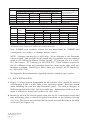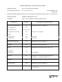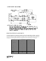
1
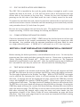
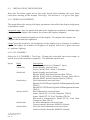
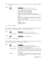
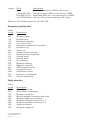
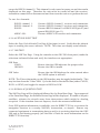
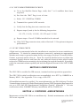
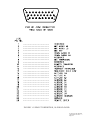
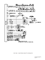
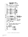
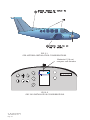
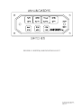
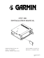
GNC 300 INSTALLATION MANUAL GARMIN INTERNATIONAL, INC. 1200 E. 151st STREET OLATHE, KANSAS 66062-3426 PART NUMBER: 190-00067-02 REVISION J, 30 MARCH 1998 Av. Kit Install. Manual 190-00067-02 Rev. J Page 1 © Copyright 1995-1998 Garmin Corporation All Rights Reserved This publication is the proprietary property of Garmin International Inc. It may not be reproduced or transmitted in any form whether printed or electronic, without the expressed written consent of Garmin International. Garmin International, Inc. 1200 E. 151st Street Olathe, KS 66062 U.S.A. REVISION RECORD ECO # Initial 5074 5219 5827 6042 6274 7708 8322 8452 Rev. Rev. Rev. Rev. Rev. Rev. Rev. Rev. Rev. Rev. Av. Kit Install. Manual 190-00067-02 Rev. J Page 2 Date of Rev. Description A, 01 Oct 1995 B, 05 Jan 1996 C, 29 Jan 1996 D, 18 June 1996 E, 23 Aug 1996 F, 22 Oct 1996 G, 10 Dec 1997 H, 28 Jan 1998 J, 30 Mar 1998 FAA Approval Initial release Clarify Mid Continent annun units GA 56 Mod 1 Add MCI options Add STC. Chg to barrel type crimp connectors. Chg Fig. 1-3A to agree with MCI's. Correct btry pinout chart Add antenna, chg btry GPN Chg to/from voltage Corr to btry pk s/n & misc. chgs. TABLE OF CONTENTS SECTION 1 GENERAL DESCRIPTION 1.1 1.2 1.2.1 1.2.2 1.2.3 1.3 INTRODUCTION TECHNICAL CHARACTERISTICS PHYSICAL CHARACTERISTICS OPERATIONAL CHARACTERISTICS INTERFACES LICENCE REQUIREMENTS SECTION 2 INSTALLATION CONSIDERATIONS 2.1 2.1.1 2.1.2 2.1.3 2.1.4 2.1.5 2.1.6 2.2 2.2.1 2.3 2.4 2.5 2.6 ANTENNA CONSIDERATIONS GPS ANTENNA LOCATION COMM ANTENNA LOCATION ELECTRICAL BONDING ANTENNA LIMITATIONS VHF COMM INTERFERENCE OF GPS COMM ANTENNA INSTALLATION CONSIDERATIONS RACK CONSIDERATIONS ACCESSIBILITY CABLING AND WIRING COOLING AIR MINIMUM INSTALLATION REQUIREMENTS EXTERNAL ALTITUDE INPUT SECTION 3 INSTALLATION PROCEDURE 3.1 3.2 3.3 3.4 3.5 3.6 INSTALLATION ACCESSORIES ANTENNA INSTALLATION CABLE INSTALLATION RACK INSTALLATION GNC 300 INSTALLATION AND REMOVAL COMM ANTENNA INSTALLATION CHECK SECTION 4 POST INSTALLATION CONFIGURATION & CHECKOUT PROCEDURE SECTION 5 CERTIFICATION SECTION 6 CONTINUED AIRWORTHINESS APPENDIX A APPENDIX B APPENDIX C CERTIFICATION DOCUMENTS CONNECTOR CHANGES STC PERMISSION Av. Kit Install. Manual 190-00067-02 Rev. J Page 3 LIST OF ILLUSTRATIONS FIGURE 1-1 1-2 1-3 1-4 2-1 2-2 2-3 3-1 3-2 3-3 3-4 3-5 Av. Kit Install. Manual 190-00067-02 Rev. J Page 4 PINOUT DEFINITION, 37 PIN DSUB PINOUT DEFINITION, 26 PIN HD-DSUB INTERCONNECT SCHEMATIC INTERCONNECT SCHEMATIC NOTES GPS ANTENNA INSTALLATION CONSIDERATIONS GNC 300 INSTALLATION CONSIDERATIONS SWITCH/ANNUNCIATOR LAYOUT STUD MOUNT GA 56 INSTALLATION FLANGE MOUNT GA 56 INSTALLATION COAX CABLE INSTALLATION AVIATION RACK DIMENSIONS AVIATION RACK INSTALLATION SECTION 1 GENERAL DESCRIPTION 1.1 INTRODUCTION This manual describes the physical, mechanical, and electrical characteristics and the installation requirements for the GNC 300 Aviation Kit. After installation of the GNC 300 system, FAA Form 337 must be completed by an appropriately certificated agency to return the aircraft to service. 1.2 TECHNICAL CHARACTERISTICS The GNC 300 offers the versatility of fixed installation in a panel mounted aviation rack as well as complete portability. For TSO Compliance, see Appendix A. The conditions and tests required for TSO approval of this article are minimum performance standards. It is the responsibility of those desiring to install this article either on or within a specific type or class of aircraft to determine that the aircraft installation conditions are within the TSO standards. The article may be installed only if further evaluation by the applicant documents an acceptable installation and is approved by the Administrator. 1.2.1 PHYSICAL CHARACTERISTICS Width: Height: Depth: GNC 300 Weight: GA 56 Antenna Weight: Aviation Rack Weight: Max Air Speed: (Structural rating for antenna) 6.25 inches 2 inches 5.65 inches 2.4 lbs. 4 oz. 10 oz. Subsonic 1.2.2 OPERATIONAL CHARACTERISTICS Operating Temperature Range: Humidity: Altitude Range: Power Range Power Requirements: -20 oC to +55 oC 95% non-condensing -1,500 to 50,000 ft. 10 to 15.1 VDC 1.2A @ 13.8v (not transmitting) 5.5A @ 13.8V (transmitting) 1.2.3 INTERFACES The GNC 300 provides interfaces to various general aviation instruments. Figure 11 defines the function of each pin on the 37 pin DSUB connector located at the back Av. Kit Install. Manual 190-00067-02 Rev. J Page 5 of the rack. Figure 1-2 defines the function of each pin in the 26 pin HD-DSUB connector (J102) located above the 37 pin connector at the back of the rack. Figures 1-3 and 1-4 defines the interconnects between the rack and other instruments. The following interfaces are provided. 1.2.3.1 37 PIN CONNECTOR (J101) CDI: (Pins 1 and 4) Capable of driving up to three 1000 ohm parallel loads, +150 millivolts full scale deflection with a maximum output of +300 millivolts. To/From: (Pins 2 and 4) Capable of driving up to three 200 ohm parallel loads, +82 millivolts full scale deflection. Units with Mod Status 1: +190 millivolts full scale deflection. Nav Flag: (Pins 3 and 4) Capable of driving up to three 1000 ohm parallel loads, 375 millivolts for flag out-of-view, and +40 millivolts for flag in-view. OBI data: (Pins 7, 8, and 23) Output providing bearing to waypoint data for a Bendix/King RMI (KI 229 or equivalent). Message annunciator: (Pin 20) Output capable of driving negative logic message annunciators by sinking up to 500mA. RS232 chan 1 output data: Output capable of driving devices as listed in Section 4. (Pin 24) Conforms to the EIA specification RS-232C. RS232 chan 2 output data: Output capable of driving devices as listed in Section 4. (Pin 19) Conforms to the EIA specification RS-232C. RS232 chan 1 input data: Input capable of receiving data from devices listed in (Pin 17) Section 4. Conforms to the EIA specification RS-232C. Arrival annunciator: (Pin 12) Output capable of driving negative logic annunciator by sinking up to 500mA. GPS approach active ann: Output capable of driving negative logic annunciator (Pin 13) by sinking up to 500mA. See GNC 300 Pilot's Guide, (GPN 190-00067-00), for more information. GPS approach arm ann: (Pin 28) Output capable of driving negative logic annunciator by sinking up to 500mA. See GNC 300 Pilot's Guide, (GPN 190-00067-00), for more information. ARINC 429 Output A & B: Output capable of interfacing with any device that has (Pins 15 and 16) an input conforming to the GAMA ARINC 429 (low speed) specification. Av. Kit Install. Manual 190-00067-02 Rev. J Page 6 NAV Super Flag Output: (Pin 10) Output capable of driving positive logic NAV Super Flag by sourcing up to 500mA for flag out of view (NAV valid). RS422 input: (Pins 11 & 27) Input capable of receiving serial OBS data from Collins Pro Line 2 EFIS DSP unit. GPS approach arm low: (Pin 9) Input, when grounded, controls approach mode. GPS OBS: (Pins 4,14,35 and 37) Capable of interfacing with a standard OBS resolver. ARINC 429 Input A & B: (Pins 32 & 33) Input capable of receiving data from ARINC 429 (low speed) devices as listed in Section 4. Battery +,-, Charge Enable Connection for GARMIN remote battery accessory. (Pins 30, 34, 29) 1.2.3.2 26 PIN CONNECTOR (J102) MIC Audio Hi and Lo:: (Pins 2 and 3) Input requiring 275mV RMS into 470 ohm load. (Standard carbon or dynamic MIC containing transistorized pre-amp.) MIC Key: (Pin4) Input, when grounded, keys the transmitter. COMM Audio Hi and Lo: (Pins 5 and 6) Output capable of driving a 500 ohm load with 100mW. MIC Intercomm: (Pin 8) Input requiring 125mV RMS into 470 ohm load. (Standard carbon or dynamic MIC containing transistorized pre-amp.) Remote Transfer: (Pin 10) Input, when grounded, swaps the active and standby COMM frequencies. TX Interlock: (Pin 12) Input, when grounded, reduces receiver sensitivity so squelch will not break when another transceiver is keyed. Altimeter input: (Pins 14-24) Capable of receiving encoded output data from any parallel altimeter device. Remote Enter: (Pin 26) Input, when ground, functions the same as the enter key on the GNC 300 front panel. Av. Kit Install. Manual 190-00067-02 Rev. J Page 7 Sequence Hold Low: (Pin 13) Input, when grounded, activates HOLD mode. See the GNC 300 Pilot's Guide (GPN 190-00067-00) for more information. 1.2.3.3 COMM Antenna Connector (J4) Capable of providing 5 watts, minimum, at 13.8V. Sensitivity of 6 dB SNR, minimum, at 2 uV hard. The COMM antenna shall be approved to TSO C37( ) and C38( ). 1.3 LICENCE REQUIREMENTS The transmitter, as installed in the aircraft, requires an Aircraft Radio Station Licence. This licence is obtained by filing the FCC Form 404. While awaiting the receipt of the station licence, a copy of FCC Form 404 is kept in the aircraft. This equipment has been type accepted by the FCC and entered on the type accepted equipment list, as GARMIN GNC 300 and must be identified as GARMIN GNC 300 on your Form 404, Aircraft Radio Station Licence application. CAUTION THE VHF TRANSMITTER IN THIS EQUIPMENT IS GUARANTEED TO MEET FEDERAL COMMUNICATIONS COMMISSION ACCEPTANCE OVER THE OPERATING TEMPERATURE RANGE. MODIFICATIONS NOT EXPRESSLY APPROVED BY GARMIN COULD VOID THE LICENCES' AUTHORITY TO OPERATE THE EQUIPMENT. SECTION 2 INSTALLATION CONSIDERATIONS Careful planning and consideration of the suggestions in this section are required to achieve the desired performance and reliability from the GNC 300. 2.1 ANTENNA CONSIDERATIONS 2.1.1 GPS ANTENNA LOCATION The GNC 300 GA 56 Antenna must be mounted on top of the aircraft. For best performance select a location with an unobstructed view of the sky above the aircraft when in level flight. Figure 2-1 illustrates a typical GPS antenna installation. For rotorcraft, locate the GA 56 antenna: 1) As far from the main rotor hub as possible. This reduces the percentage of time the blade blocks the antenna. 2) As far below the blade surface as possible if installing the antenna under the blade. This reduces signal distortion caused by the blades. Av. Kit Install. Manual 190-00067-02 Rev. J Page 8 The antenna should be located at least 3 feet from transmitting antennas such as VHF Comm, HF transmitter, DME, Transponder, and Radar. 2.1.2 COMM ANTENNA LOCATION The COMM antenna should be well removed from all projections, engines and propellers. The ground plane surface directly below the antenna should be a flat plane over as large an area as possible (18 inches square minimum). The antenna should be mounted a minimum of 6 feet away from any DME antennas, 4 feet from any ADF sense antennas, and a minimum of 3 feet from the GNC 300 and its GPS antenna. The GNC 300 COMM antenna connector is specified to have installed GPN 330-0006700 (1.57542 GHz notch filter) to minimize interfering harmonics. 2.1.3 ELECTRICAL BONDING No special precautions need to be taken to provide a bonding path between the GPS antenna and the aircraft structure. Follow the manufacturers instructions for the COMM antenna. 2.1.4 ANTENNA LIMITATIONS GARMIN'S GA 56 Antennas are recommended for installations where the airspeed of the aircraft will be subsonic. GARMIN's GA 56, Mod 1 or later, must be used. See the COMM antenna specification for its limitations. 2.1.5 VHF COMM INTERFERENCE OF GPS On many panel-mounted aircraft, VHF COMM's can radiate strong harmonics from the unit and antenna. The GNC 300 COMM section will not interfere with its GPS section. However, placement of the GNC 300 GPS antenna relative to all COMM's and COMM antenna, including its own, is critical. Use the following guidelines, in addition to others in this document, when locating the GNC 300 and its antennas. GPS Antenna: GNC 300: Locate as far as possible from all COMM antennas and all COMMs (including the GNC 300). The GPS antenna will be much less sensitive to COMM antennas that use a 1.57542 GHz notch filter. Locate as far as possible from all COMM antennas. Av. Kit Install. Manual 190-00067-02 Rev. J Page 9 If a COMM antenna is found to be the problem, a 1.57542 GHz notch filter (GPN 33000067-00) may be installed in the VHF COMM coax, as close to the COMM as possible. This filter (GPN 330-00067-00) is required for the GNC 300 transmitter). If a COMM is found to be radiating, the following can be done: 1) 2) 3) Replace or clean VHF COMM rack connector to assure good coax ground. Place a grounding brace between the GNC 300, VHF COMM, and ground. Shield the VHF COMM wiring harness. 2.1.6 COMM ANTENNA INSTALLATION INSTRUCTIONS The COMM antenna should be installed according to the manufacturer's recommendations. 2.2 RACK CONSIDERATIONS 2.2.1 ACCESSIBILITY Plan a location which gives the pilot complete and comfortable access to the entire keypad and which is plainly visible from the pilots perspective. Check that there is adequate depth for the rack in the instrument panel. A location away from heating vents or other sources of heat generation is optimal. Figure 2-2 illustrates a typical aviation rack installation. 2.3 CABLING AND WIRING The recommended antenna cable type for both antennas is M17/155-0001 (RG-58A/ U) per MIL-C-17. Maximum allowable length for the GPS antenna using this cable type is 40 feet. Other cable types with 50 ohms nominal impedance and longer lengths can be used for the GPS antenna, provided the installer insures that the attenuation does not exceed 10dB at 1.5 GHz for the specific installation. Check that there is ample space for the cabling and mating connectors. Avoid sharp bends in cabling, particularly the COMM antenna cable, and routing near aircraft control cables. Cabling for the GNC 300 should not be routed near components or cabling which are sources of electrical noise. Do not route the COMM antenna cable near any ADF antenna cables. Route the GPS antenna cable as far as possible away from all COMMs and COMM antenna cable. 2.4 COOLING AIR Cooling air is not required for the GNC 300 but is highly recommended because, as with any electronic equipment, reduced operating temperature can contribute to increased reliability. Additionally, location of the GNC 300 in a stack of other power Av. Kit Install. Manual 190-00067-02 Rev. J Page 10 dissipating equipment can produce unacceptably high ambient air temperatures around the unit. A 5/8 inch diameter air fitting is provided on the rear of the mounting rack for the purpose of admitting cooling air under such conditions. 2.5 MINIMUM INSTALLATION REQUIREMENTS Below is a list of required devices for A1 and A2 certification. Figure 1-3 shows various equipment that can be used. For a specific list of equipment used in the initial STC see GPN 190-00067-06. Deviations from this equipment should be approved by the FAA or the governing organization. Pressure Altitude Device This device delivers pressure altitude data to the GNC 300. This data can come from an encoder or serializer. Manual Course Device This device delivers the manual course selected to the GNC 300. Course information can come from an analog resolver or from an EFIS via the ARINC 429 bus or RS-422 bus. HSI/CDI Device This device displays Nav Flag, Left/Right and To/From. This can be displayed on the EFIS or HSI. External Annunciators NAV GPS NAV/GPS HOLD AUTO GPS Sequence Approach Actv Approach Arm GPS Approach Message Arrival and Switches Annunciator Annunciator Switch Annunciator Annunciator Switch Annunciator (not required for A2) Annunciator (not required for A2) Switch (not required for A2) Annunciator Annunciator The installer is advised to ensure that the switches and annunciators are the functional equivalent to and perform at least as well as the GARMIN devices used in the initial STC. The GARMIN switches and annunciators are sunlight readable and in the primary view of the pilot. Figure 2-3 shows what the GARMIN switch/annunciators look like. For other information concerning switch/annunciators see the Generic Airplane Flight Manual Supplement (190-00067-04) as well as current FAA directives. Qualified GPS Antenna This antenna must be one of those listed in the accessories list. Av. Kit Install. Manual 190-00067-02 Rev. J Page 11 2.6 EXTERNAL ALTITUDE INPUT Pressure altitude input from an external source may be derived from a RS-232 compatible serial altitude input or Parallel Gray Code/Gillham Altitude as described in Section 4 of this manual. Gillham Altitude is not required when serial altitude is used. SECTION 3 INSTALLATION PROCEDURE 3.1 INSTALLATION ACCESSORIES The following installation accessories are available: ANTENNA AND RACK OPTIONS 010-10040-01 GA 56 ANTENNA KIT, W/O CABLE (Mod 1, or later) Includes: 011-00134-00 GA56 ANTENNA SUB-ASSEMBLY 1 115-00031-00 BACKING PLATE 1 210-10004-09 NUT, SELF-LOCKING, #8-32 4 253-00002-00 ANTENNA GASKET 1 010-10040-02 GA 56 FLANGE MOUNT ANTENNA (Mod 1, or later) Includes: 011-00147-00 FLANGE MOUNT GA56 ANTENNA SUB-ASSEMBLY 1 115-00080-00 NUT PLATE 1 211-62212-14 SCREW, #10-32 X 5/8 4 253-00011-00 ANTENNA GASKET 1 320-00003-00 15 FT LOW-LOSS AVIATION ANT. EXTENSION CABLE WITH RIGHT ANGLE BNC CONNECTOR 320-00003-02 30 FT LOW-LOSS AVIATION ANT. EXTENSION CABLE WITH RIGHT ANGLE BNC CONNECTOR 330-00087-00 CONNECTOR, BNC, MALE, CLAMP Note: One cable assembly and one BNC connector are required to make the antenna cable, or it can be fabricated by the installer from materials meeting the requirements of paragraph 2.3. 011-00154-00 MOUNTING RACK, (WITHOUT CONNECTORS) Note: A mounting rack is required for approved installations. The following hardware is required for installation of the mounting rack, but is not provided: #6-32 Flat Head Screw (4 ea.) #6-32 Self-locking Nut (4 ea.) 011-00313-00 CONNECTOR, (J1 and J2) Kit DATA BASE OPTIONS 010-10051-00 MEMORY 010-10051-01 MEMORY 010-10051-02 MEMORY 010-10032-03 MEMORY CARD CARD CARD CARD - WORLDWIDE DATABASE - AMERICAS DATABASE - INTERNATIONAL DATABASE - USER ANNUNCIATOR OPTIONS GPN MID-CONTINENT P/N 013-00029-10 MD41-448 013-00029-11 MD41-444 013-00029-12 MD41-448 (5V) 013-00029-15 MD41-458 013-00029-16 MD41-454 013-00029-17 MD41-458 (5V) DESCRIPTION INTEGRATED SW/ANN INTEGRATED SW/ANN INTEGRATED SW/ANN INTEGRATED SW/ANN INTEGRATED SW/ANN INTEGRATED SW/ANN UNIT, UNIT, UNIT, UNIT, UNIT, UNIT, MISCELLANEOUS OPTIONS 010-10075-00 PC KIT 190-00067-00 GNC 300 PILOT'S GUIDE 190-00067-01 GNC 300 QUICK REFERENCE GUIDE 190-00067-06 GNC 300 IN MOONEY M20J DOCUMENTED INSTALLATION 330-00067-00 GPS 1.57542 GHZ NOTCH FILTER 362-00014-00 WALL ADAPTER - 110/220VAC 010-10057-00 28 TO 14V CONVERTER (Consists of 011-00181-00) 010-10074-00 REMOTE BATTERY PACK (Consists of 011-00182-00) Av. Kit Install. Manual 190-00067-02 Rev. J Page 12 HOR, 28V HOR, 14V HOR, 28V (5V LIGHTING) VERT, 28V VERT, 14V VERT, 28V (5V LIGHTING) The following installation accessories are required but not provided: COMM ANTENNA: HEADPHONES: MICROPHONE: 3.2 BROAD BAND 50 OHM VERTICALLY POLARIZED WITH COAXIAL CABLE. 500 OHM NOMINAL IMPEDANCE LOW IMPEDANCE CARBON OR DYNAMIC WITH TRANSISTORIZED PRE-AMP. ANTENNA INSTALLATION For the COMM antenna, follow the manufacturers instructions. The remainder of this section applies to the GPS antenna. The GA 56 Antenna outline and footprint dimensions are shown in Figures 3-1 and 3-2. A. Using the backing plate as a template, mark the location of the mounting holes and the through hole for coax cable. Drill or punch the holes. B. The antenna installation must provide adequate support for the antenna considering a maximum drag load of 5 lbs. for the GA 56 antennas (at subsonic speed). Install a doubler plate to reinforce thin skinned aircraft. Observe guidelines for acceptable installation practices as outlined in AC 43.13-2A. C. Seal the antenna and gasket to the fuselage using a good quality electrical grade sealant. Use caution to insure that the antenna connector is not contaminated with sealant. Insure that the mounting screws are fully tightened and that the antenna base is well seated against the gasket. CAUTION: Do not use construction grade RTV sealant or sealants containing acetic acid. These sealants may damage the electrical connections to the antenna. Use of these type sealants may void the antenna warranty. 3.3 CABLE INSTALLATION A. Route the coax cable to the rack location keeping in mind the recommendations of Section 2. Secure the cable in accordance with good aviation practice. B. Trim the coaxial cable to the desired length and install the BNC connector (33000087-00) per the cabling instructions on Figure 3-3. If the connector is provided by the installer, follow the connector manufacturer's instructions for cable preparation. C. Contacts for the 37 and 26 pin connectors must be crimped into the individual wires of the aircraft wiring harness. The following tables list contact part numbers (for reference) and recommended crimp tools: Av. Kit Install. Manual 190-00067-02 Rev. J Page 13 Contacts Standard Density Connectors 37 socket connector (J1 on unit) Garmin p/n military p/n Amp Positronic ITT Cannon 9 pin connector (on battery pack) Hi Dens. Connector 26 pin connector (J2 on unit) 20-24 AWG socket contact 18 AWG socket contact 20-24 AWG pin contact 18 AWG pin contact 22-28 AWG pin contact 336-00022-00 M39029/63-368 205090-1 M39029/63-368 031-1007-042 336-00023-00 n/a n/a FC6018D see note 336-00024-00 M39029/64-369 205089-1 M39029/64-369 330-5291-037 336-00025-00 n/a n/a MC6018D see note 336-00021-00 M39029/58-360 204370-2 M39029/58-360 030-2042-000 Tools Hand Crimping Tool military p/n M22520/2-01 Positronic 9507 ITT Cannon 995-0001-584 Amp 601966-1 Daniels AFM8 Astro 615717 Standard Density Connectors (size 20 contacts) Hi Dens. Connector (size 22D) pin or socket contacts (20-24 AWG) pin or socket contacts (18 AWG) pin contacts (22-28 AWG) positioner M22520/2-08 9502-5 995-0001-604 601966-5 K13-1 615725 positioner n/a 9502-11 see note n/a K774 see note positioner M22520/2-09 9502-3 995-0001-739 601966-6 K42 615724 insert/extract M81969/1-02 M81969/1-02 980-2000-426* 91067-2 M24308/1-02 M81969/1-02 insert/extract M81969/1-02 M81969/1-02 274-7048-000* n/a M24308/1-02 M81969/1-02 insert/extract M81969/1-04 M81969/1-04 n/a 91067-1 M24308/18-1 M81969/1-04 * Insert/extract tools from ITT Cannon are all plastic, others are plastic with metal tip. Non- GARMIN part numbers shown are not maintained by GARMIN and consequently are subject to change without notice. NOTE: Alternate contacts for 18 AWG wire: As an alternate to the Positronic contacts listed (and provided in the install kit), the installer may use contacts made by ITT Cannon as follows: Socket contact - ITT Cannon p/n: 031-10007001, Pin contact - ITT Cannon p/n: 330-5291-055. These contacts require the use of a different crimp tool positioner than that shown in the table, with part numbers as follows: Daniels p/n: K250, Astro p/n: 616245, or ITT Cannon p/ n: 980-00005-722. See Appendix B for information regarding obsolete stamped type contacts. 3.4 RACK INSTALLATION A. Figure 3-4 shows outline dimensions for the aviation rack. Install the rack in a rectangular 6.320" x 2.000" hole in the instrument panel. Exercise caution when installing the rack into the instrument panel. The rack is designed to facilitate removal of the GNC 300 for portable use. Deformation of the rack may make it difficult to install and remove the GNC 300. B. Install the rack in the aircraft panel using four #6-32 countersunk screws and four self-locking nuts or other FAA approved methods as per Advisory Circular 43.13-1A. The screws are inserted from the inside through the holes in the sides of the rack (see Figure 3-5). Av. Kit Install. Manual 190-00067-02 Rev. J Page 14 3.5 GNC 300 INSTALLATION AND REMOVAL The GNC 300 is installed in the rack by gently sliding it straight in until it rests against the back of the rack. A 3/32 inch hex drive tool is then inserted into the access hole at the bottom of the unit face. Rotate the hex tool clockwise while pressing on the left side of the Bezel until the unit is firmly seated in the rack. To remove the unit from the rack, insert the hex drive tool into the access hole on the unit face and rotate counter-clockwise until the mounting screw turns freely and the unit protrudes about 3/8 inch from the panel. Be sure not to over tighten the unit into the rack. The application of hex drive tool torque exceeding 15 in*lbs can damage the locking mechanism. 3.6 COMM ANTENNA INSTALLATION CHECK Check for insertion loss and VSWR. VSWR should be checked with an in-line type wattmeter inserted in the coaxial transmission line between the transceiver and the antenna. Any problem with the antenna installation will most likely be seen as a high reflected power. A VSWR of 3:1 will result in a 25% loss in power. SECTION 4 POST INSTALLATION CONFIGURATION & CHECKOUT PROCEDURE Before starting the below operations, unit initialization must occur. Do this by first removing any data cards and then turning the unit on. Press enter in response to Select operating mode Normal ok?. Press enter in response to No Jeppesen database rte/prx limited to user wpts ok?. After the satellite status page is displayed for 5 seconds the unit may be turned off. Proceed with the following steps. 4.1 TEST MODE OPERATIONS With power applied to the aviation rack and the GNC 300 unit off, depress and hold the ENT key and turn the unit on (release the ENT key when the display activates). The first page displayed is the Display Test Page. While in TEST MODE, test pages can be selected by ensuring the cursor is off and rotating the outer knob either direction. To change data on the displayed test page, depress the CRSR key and the cursor will highlight the standby COMM frequency. Press cursor again to move to configuration selections. The inner knob will change the data on the selected field. The ENT key or the outer knob will advance to the next field on the page. Pressing the CRSR key again will stop the current field from flashing, allowing the outer knob to select the next test page. The ENT key is used to enter a new value into the OBI data field after selecting the desired value using the inner and outer knobs (see the appropriate chapter of the Pilot's Guide for more information on page and data selection). Note that some pages found in test mode are intended for bench testing and are not discussed here. Av. Kit Install. Manual 190-00067-02 Rev. J Page 15 4.2 INSTALLATION CONFIGURATION Note that the below pages are in the order found when rotating the outer knob clock-wise starting at the Display Test Page. See Section 4.1 to get to this page. 4.2.1 DISPLAY ADJUSTMENT This page allows the setting of display parameters that affect the display brightness in automatic mode. response time sets the speed with which the brightness responds to ambient light changes. The higher the number the slower the display responds. min sets the minimum brightness of the display. The higher the number the brighter the minimum brightness. slope sets the sensitivity the brightness of the display has to changes in ambient light. The higher the number the brighter the display will be for a given increase in ambient lighting. 4.2.2 I/O CHANNEL 1 Select the I/O CHANNEL 1 Test Page. Change the selectable input and output to match that of the installed equipment. The available options are: Input: Field off icarus-alt shadin-alt shadin-fuel arnav/ei-fuel shadin-adc shadin-fadc Av. Kit Install. Manual 190-00067-02 Rev. J Page 16 Description No units connected to Channel 1 input Serial altitude received from: Icarus, Model 3000, Mode C Serializer Serial altitude received from: Shadin 9000T Serializer System (Non-TSO'd) Shadin 9200T Series Serializer System (Non-TSO'd) Shadin 8800T Series Encoder System (TSO'd) Fuel information received from: Shadin 91204XT Series Digital Fuel Management System (TSO'd) Shadin 91053XT Series Digital Fuel Management System (TSO'd) Fuel information received from: Arnav, Model FC-10, Fuel Computer (TSO'd) Arnav, Model FT-10, Fuel Totalizer (TSO'd) Electronics International, Model FP-5L, Fuel Flow Computer (Non-TSO'd) Air data information received from: Various models from the 9628XX-X family Fuel/Air data information received from: Various models from the 9628XX-X family Note: Verify with manufacturer of data input device that unit supports GARMIN interface. Output: Field off aviation Description No units connected to Channel 1 output Serial position, velocity and navigation data to: Argus, Model 3000, Moving Map Argus, Model 5000, Moving Map Argus, Model 7000, Moving Map Stormscope, Series II with Navaid, Moving Map Shadin, 91204X[T] Digital Fuel Management System (TSO'd) Shadin, 91053X[T] Digital Fuel Management System Electronics International, Model FP-5L, Fuel Flow Computer (Non-TSO'd) Shadin, Model 9628XX-X Fuel/Airdata Computer (TSO'd) GARMIN, GPS 195 GARMIN, GPS III 4.2.3 RS-422 CHANNEL Select the RS-422 Channel Test Page. Change the selectable input and output to match that of the installed equipment. The available options are: Input: Field off Collins PL2 DSP Description No units connected to the RS-422 input Collins Pro Line 2 Display Select Panel connected Output: Field off Description NO AVAILABLE SELECTIONS 4.2.4 ARINC 429 CHANNEL Select the ARINC 429 Channel Test Page. Change the selectable output to match that of the installed equipment. The available options are: Input: Field off Selected Course Course/heading Heading Description No units connected to ARINC 429 input Any ARINC 429 compatible unit that transmits the Selected Course word (label 100) Any ARINC 429 compatible unit that transmits the Selected Course (label 100), as well as the True heading (label 314) and/or Magnetic heading (label 320) words Any ARINC 429 compatible unit that transmits the True heading (label 314) and/or Magnetic heading (label 320) words Av. Kit Install. Manual 190-00067-02 Rev. J Page 17 Output: Field off Collins PL2 EFS King EFS 40/50 w/o GAMA labels Description No units connected to ARINC 429 output Collins Pro Line 2 EFIS connected (w/ GAMA) King Radio EFIS 40 or 50 connected (w/ GAMA) Any unit that receives standard 429 output Below is a list of labels output by the GNC 300: Navigation/position data Label (octal) Description 100 114 115 116 121 251 252 310 311 312 313 314 320 147* 261* 275* 326* 351* 352* Selected course Desired track Bearing to waypoint Cross track error Horizontal command (to autopilot) Distance to go Time to go Present position latitude Present position longitude Ground speed Ground track True heading Magnetic heading Magnetic variation GPS navigation mode Navigation status Lateral scale factor Distance to destination Time to destination Flight plan data Label (octal) 074* 075* 113* 300* 303* 304* 305* 306* 307* Description Flight plan header Active from/to waypoints Message checksum Station magnetic variation/type/class Message length/type/number Waypoint identifier characters 1-3 Waypoint identifier characters 4-6 Waypoint latitude Waypoint longitude Av. Kit Install. Manual 190-00067-02 Rev. J Page 18 Identification data Label (octal) Description 377 371* Equipment identifier General Aviation equipment identifier *These labels are formatted per the General Aviation Manufacturers Association (GAMA) definition. Note that the use of a 429 device w/o GAMA will cause the loss of the above asterisked labels. Some may be required for A1 certification. For example, label 326 changes the CDI scale for approach. 4.2.5 CDI CALIBRATION Select the test page displaying CDI output calibration. Place the cursor on the alignment field by using the outer knob. Use the inner knob to adjust the CDI needle until it is centered. Once centered, turn the cursor off to complete the calibration process. 4.2.6 SELECTED COURSE CALIBRATION Select the test page displaying the selected course input. Using an extremely accurate input source, input 150° to the GNC 300. The input course will indicate close to 150 and a Calib? field will appear in the lower right corner. Selecting the Calib? field will calibrate the GNC 300 to match the input source. Verify OBS operation by checking that the bearing displayed on the GNC 300 is within 2° of the selected bearing. Do this for every multiple of 30° around the OBS. 4.2.7 APPROACH SETTINGS Select the Approach Settings Test Page. Move the cursor over the approach switch field to change the installation state. The available options are: Appr switch: Field none instld Description The approach switch is not present The approach switch is installed NOTE: To verify the installation of the approach switch, the instld setting requires the approach switch to be pressed to confirm its presence. The following prompt is displayed in this case: press appr switch to confirm along with a ? following instld. When the switch press is recognized the prompts are cleared and the instld setting is confirmed. Av. Kit Install. Manual 190-00067-02 Rev. J Page 19 4.2.8 CONFIGURATION Select the Configuration Test Page. Change the selectable Strap and Fuel selections to match that of the aircraft. The available options are: Strap: Field Description Lnav 1 Lnav 2 common Number 1 (Pilot) long range NAV Number 2 (Co-Pilot) long range NAV Common long range NAV NOTE: The strap option affects the interpretation of RS-422 and ARINC 429 input data For RS-422 input data the following applies: Lnav 1 Lnav 2 common Only data marked for Lnav 1 is used Only data marked for Lnav 2 is used Data marked for either Lnav 1 or Lnav 2 is used For ARINC 429 input data the following applies: Lnav 1 Lnav 2 common Only data with SDI=0 or SDI=1 is used Only data with SDI=0 or SDI=2 is used Only data with SDI=0 is used NOTE: SDI=0 is an all call. Fuel: av gas Jet A Jet B Using Aviation gas (5.8 lbs/gal) Using Jet A/Jet A-1 fuel (6.7 lbs/gal) Using Jet B (JP-4) fuel (6.5 lbs/gal) NOTE: The Fuel option is used to designate the type of fuel used so that the correct fuel density will be used in calculations. 4.2.9 REMOTE BATTERY SETTINGS Remote Battery: none instld NOTE: If instld is selected when a battery is not installed erroneous voltages will be shown on the Power Test page and invalid battery messages will be issued in normal operating modes. Low Battery: selectable between 8.0 volts and 9.6 volts by 0.2 volt steps NOTE: In normal operating modes, The Battery Low message will be issued when the battery voltage is below the low battery value. The default value is 9.0 volts. Av. Kit Install. Manual 190-00067-02 Rev. J Page 20 4.2.10 I/O CHANNEL 2 Note: This page is not found in the Test Pages but is included here to aid installation. For more information see SET pages in the Pilot's Guide (GPN 190-00067-00). Select the I/O CHANNEL 2 Set Page. Change the selectable input and output to match that of the installed equipment. The available options are: Input: Field off Description NO AVAILABLE SELECTIONS Output: Field off plotting Description No units connected to Channel 2 output Serial position, velocity, navigation and satellite data to: NMEA 0183 Version 2.0 compatible mapping device or GARMIN PC software. NOTE: Below is a list of the NMEA 0183 sentences (with maximum number of characters) that the GNC 300 transmits. RMC -70 characters GGA -72 characters GSA -57 characters GSV -140 characters (70 characters x 2 sentences) RMB -70 characters BOD -35 characters WPL -38 characters *PGRME -35 characters *GARMIN proprietary accuracy error sentence that is not a part of the NMEA 0183 standard. 4.3 GROUND TEST The GNC 300 ground test procedure incorporates a series of display pages to test CDI/ flag, OBI, annunciators, external switches, altitude inputs, and power functions of the unit. Note that the below pages are in the order found when rotating the outer knob counterclockwise starting at the Display Test page. See Section 4.1 to get to this page. 4.3.1 POWER TEST Select the Power Test page. This page reports the status of the GNC 300 external power source, remote battery and internal memory battery. In the below voltage represents the voltage currently measured for that function. Av. Kit Install. Manual 190-00067-02 Rev. J Page 21 The first line, below the COMM frequencies, shows the source of external power as shown below: External Power voltage Battery Power Wall Adapter The presence of a Wall Adapter will override the other two sources. Battery Power will not be shown unless on the Remote Battery Settings Page the Remote Battery is selected as instld. The higher voltage of External Power or Battery Power will determine which is shown. The next line shows the status of the Remote Battery as shown below: Rmt Bat none (If on the Remote Battery Settings Page Remote Battery is selected as none) Rmt Bat voltage mode auto status mode represents the mode of the charger enable to the remote battery pack and is selectable. On enables the charger. Off disables the charger. Auto enables the charger if the External Power is the current source and its voltage is high enough. When in Auto mode auto status will be either on or off reflecting whether the charger is enabled or disabled. The next line reports the status of the internal memory battery as shown below: Mem Bat ok/low. Note that the TX field will light on the display but the transmitter will not actually transmit when the GNC 300 is powered from the wall charger. 4.3.2 CDI AND FLAG TEST Select the CDI Test Page. Using the controls on the GNC 300 front panel, make the selections indicated below and verify the interfaces as appropriate: CDI Full scale left Full scale right Centered Ensure the CDI is deflected full scale left (5 dots) Ensure the CDI is deflected full scale right (5 dots) Ensure the CDI is centered TO/FROM/FLAG TO FROM FLAG Ensure TO flag is visible Ensure FROM flag is visible Ensure TO and FROM are NOT visible CDI FLAG IN VIEW OUT OF VIEW Ensure CDI flag is in view Ensure CDI flag is out of view Av. Kit Install. Manual 190-00067-02 Rev. J Page 22 SUPERFLAG IN VIEW OUT OF VIEW Ensure superflag in view Ensure superflag out of view 4.3.3 ANNUNCIATOR TEST Select the Annunicator Test Page. Using the controls on the GNC 300 front panel make the selections indicated below and verify the interfaces as appropriate: MSG Annunciator OFF ON Ensure the Message Annunciator is OFF Ensure the Message Annunciator is ON Arrival Annunciator OFF ON Ensure the Arrival Annunciator is OFF Ensure the Arrival Annunciator is ON Approach Annunciator OFF ACTV ARM Ensure all Approach Annunciators are OFF Ensure the Approach Active Annunciator is ON (Arm is OFF) Ensure the Approach Arm Annunciator is ON (Active is OFF) 4.3.4 EXTERNAL SWITCH TEST Select the External COM Switches Page. For each of the following installed remote switches perform the following: Press Remote Enter and verify the Rmt ent field changes from off to on. Press PTT and verify the PTT field changes from off to on. Press Remote Transfer and verify the Rmt xfr field changes from off to on. Next, select the External Switches Page. For each of the following installed remote switches perform the following: Press GPS Appr and verify the appr field changes from off to on. Press GPS Sequence and verify the hold field changes from off to on. 4.3.5 COMMUNICATIONS LOOPBACK TEST This page displays the results of communication loop back tests. Four channels are tested: RS232 channels 1 and 2, RS 422 and ARINC 429. Results of the test are either OPEN or OK. Open means the channel's transmitter and receiver are not connected or the test failed. The tests are performed continuously while on this page Av. Kit Install. Manual 190-00067-02 Rev. J Page 23 except for RS232 channel 2. This channel is only tested at power on and the results displayed on this page. Therefore the unit must be turned off and the receiver/ transmitter connected or disconnected and then turn the unit on to perform the test. To test the channels: RS232 channel 1: RS232 channel 2: RS422: ARINC 429: Connect RS232 channel 1 receiver and transmitter Connect RS232 channel 2 receiver and transmitter Connect RS232 channel 1 to RS422 LOW (pin 27) and ground RS422 HI (pin 11) Connect ARINC 429 receiver and transmitter 4.3.6 ALTITUDE INPUT TEST Select the Gray Code Altitude Test Page if this input is used. Verify that the altitude input is reading the correct altitude. NOTE: This does not display serial altitude. 4.3.7 OBI TEST Select the OBI Test Page. Using the controls on the GNC 300 front panel, make the selections indicated below and verify the interfaces as appropriate: OBI Data VALID INVALID OBI Value Ensure that the OBI indicates the proper value Ensure the OBI is invalid Ensure that the OBI displays the value entered when the VALID option is selected NOTE: The 3 lines that make up the OBI interface may be toggled individually. This may be done from the Value field. Cycle this field to the desired line (either CLOCK, DATA or SYNC) and toggle the output to HIGH or LOW. 4.3.8 SIGNAL ACQUISITION TEST The Self Test Page will be displayed followed by the Data Base Page. Upon approval of the Data Base Page, the Satellite Status Page will be displayed. If unable to acquire satellites, relocate the aircraft away from obstructions which might be shading reception. If the situation does not improve, check the antenna installation. Once GPS position information is available, use the DIRECT-TO key to activate the navigation function to a nearby NAVAID, intersection, or airport. Ensure any connected equipment is transmitting data to and/or is receiving data from the GNC 300 and is functioning properly (see the Pilot's Guide for more information on the DIRECT-TO function). Av. Kit Install. Manual 190-00067-02 Rev. J Page 24 4.3.9 VHF COMM INTERFERENCE CHECK a) Go to the Satellite Status Page, verify that 7 to 8 satellites have been acquired b) See that the NAV flag is out of view c) Select 121.15 MHZ on COMM1 d) Transmit for a period of 20 seconds e) Verify that the flag does not come into view f) Repeat steps d) and e) for the following frequencies: 121.175, 121.20, 131.250, 131.275 and 131.300 g) Repeat steps c-f for all COMMs installed in the aircraft h) If the NAV flag comes into view, refer to Section 2.1.5 for options to improve performance. 4.3.10 VHF COMM CHECK A flight test is recommended after the installation is completed to insure satisfactory performance. To check the communications transceiver, maintain an appropriate altitude and contact a ground station facility at a range of at least 50 nautical miles. Contact a ground station close in. Press the squelch disable button to defeat the automatic squelch feature and listen for any unusual electrical noise which would reduce the COMM receiver sensitivity by increasing the squelch threshold. If possible, verify the communications capability on both the high and low end of the VHF COMM band. SECTION 5 CERTIFICATION The GNC 300 is certified for IFR enroute, terminal and non-precision approaches. The GNC 300's initial certification was accomplished via a STC by GARMIN in a Mooney M20J. See Appendix C for a copy of the STC. All installations must be certified. For more information, see FAA Advisory Circular Airworthiness Approval of Global Positioning System (GPS) Navigation Equipment for use as a VFR and IFR Supplemental Navigation System, Appendix 1. All new certifications after GARMIN's Mooney installation will be Follow-On. SECTION 6 CONTINUED AIRWORTHINESS Maintenance of the GNC 300 is on condition only. Periodic maintenance of the GNC 300 is not required. Av. Kit Install. Manual 190-00067-02 Rev. J Page 25 FIGURE 1-1 PINOUT DEFINITION, 37 PIN DSUB Av. Kit Install. Manual 190-00067-02 Rev. J Page 26 FIGURE 1-2 PINOUT DEFINITION, 26 PIN HD-DSUB Av. Kit Install. Manual 190-00067-02 Rev. J Page 27 FIGURE 1-3A INTERCONNECT SCHEMATIC Av. Kit Install. Manual 190-00067-02 Rev. J Page 28 FIGURE 1-3B INTERCONNECT SCHEMATIC Av. Kit Install. Manual 190-00067-02 Rev. J Page 29 FIGURE 1-3C INTERCONNECT SCHEMATIC Av. Kit Install. Manual 190-00067-02 Rev. J Page 30 FIGURE 1-4 INTERCONNECT SCHEMATIC NOTES Av. Kit Install. Manual 190-00067-02 Rev. J Page 31 Antenna masked by vertical T tail, or dorsal fin fin, OK Antenna must be top of aircraft. on FIG 2-1 GPS ANTENNA INSTALLATION CONSIDERATIONS Maintain 6"(16 cm) compass safe distance ACTV GARMIN GNC 250 STBY CLR ENT CRSR SQ D NRST RTE WPT NAV MSG FIG 2-2 GNC 300 INSTALLATION CONSIDERATIONS Av. Kit Install. Manual 190-00067-02 Rev. J Page 32 FIGURE 2-3 SWITCH/ANNUNCIATOR LAYOUT Av. Kit Install. Manual 190-00067-02 Rev. J Page 33 FIG 3-1 STUD MOUNT GA 56 ANTENNA INSTALLATION Av. Kit Install. Manual 190-00067-02 Rev. J Page 34 FIGURE 3-2 FLANGE MOUNT GA 56 ANTENNA INSTALLATION Av. Kit Install. Manual 190-00067-02 Rev. J Page 35 FIGURE 3-3 COAX CABLE INSTALLATION Av. Kit Install. Manual 190-00067-02 Rev. J Page 36 FIGURE 3-4 AVIATION RACK DIMENSIONS Av. Kit Install. Manual 190-00067-02 Rev. J Page 37 FIGURE 3-5 AVIATION RACK INSTALLATION Av. Kit Install. Manual 190-00067-02 Rev. J Page 38 APPENDIX A CERTIFICATION DOCUMENTS (19,5210(17$/48$/,),&$7,21)250 120(1&/$785( *1&*36$,5%251(51$9&2006<67(0 7<3(02'(/3$5712 *36762&&/$66$ 9+)&20075$160,77(5762&G&/$66 9+)&2005(&(,9(5762&G&/$66& 0$18)$&785(5 663(&,),&$7,21$1'2527+(5$33/,&$%/(63(&,),&$7,21 0$18)$&785(5 *$50,1,17(51$7,21$/,1& $''5(66 (VW675((72/$7+(.$16$6 &RQGLWLRQV 7HPSHUDWXUHDQG$OWLWXGH 6HFWLRQ /RZ7HPSHUDWXUH +LJK7HPSHUDWXUH ,Q)OLJKW/RVVRI&RROLQJ $OWLWXGH 'HFRPSUHVVLRQ 2YHUSUHVVXUH 'HVFULSWLRQRI&RQGXFWHG7HVWV (TXLSPHQWWHVWHGWR&DWHJRULHV$'H[FHSWDV QRWHG &RROLQJDLUQRWUHTXLUHG 7HPSHUDWXUH9DULDWLRQ (TXLSPHQWWHVWHGWR&DWHJRU\& +XPLGLW\ (TXLSPHQWWHVWHGWR&DWHJRU\$ 6KRFN (TXLSPHQWWHVWHGSHU'2&3DU 2SHUDWLRQDO &UDVK6DIHW\ 9LEUDWLRQ (TXLSPHQWWHVWHGZLWKRXWVKRFNPRXQWVWR &DWHJRULHV%0DQG17DEOH ([SORVLRQ (TXLSPHQWLGHQWLILHGDV&DWHJRU\;QRWHVWUHTXLUHG :DWHUSURRIQHVV (TXLSPHQWLGHQWLILHGDV&DWHJRU\;QRWHVWUHTXLUHG )OXLGV6XVFHSWLELOLW\ (TXLSPHQWLGHQWLILHGDV&DWHJRU\;QRWHVWUHTXLUHG $Y.LW,QVWDOO0DQXDO 5HY3DJH 7KHLQIRUPDWLRQOLVWHGEHORZSURYLGHVH[DPSOHVRQO\,WLVQRWLQWHQGHGWREHDFRPSUHKHQVLYH OLVWLQJRIDOOWHVWFRQGLWLRQV &RQGLWLRQV 6HFWLRQ 'HVFULSWLRQRI&RQGXFWHG7HVWV 6DQGDQG'XVW (TXLSPHQWLGHQWLILHGDV&DWHJRU\;QRWHVWUHTXLUHG )XQJXV (TXLSPHQWLGHQWLILHGDV&DWHJRU\;QRWHVWUHTXLUHG 6DOW6SUD\ (TXLSPHQWLGHQWLILHGDV&DWHJRU\;QRWHVWUHTXLUHG 0DJQHWLF(IIHFW (TXLSPHQWWHVWHGLV&ODVV= 3RZHU,QSXW (TXLSPHQWWHVWHGWR&DWHJRU\% 9ROWDJH6SLNH (TXLSPHQWWHVWHGWR&DWHJRU\$ $XGLR)UHTXHQF\ 6XVFHSWLELOLW\ (TXLSPHQWWHVWHGWR&DWHJRU\% ,QGXFHG6LJQDO 6XVFHSWLELOLW\ (TXLSPHQWWHVWHGWR&DWHJRU\$ 5DGLR)UHTXHQF\ 6XVFHSWLELOLW\ (TXLSPHQWWHVWHGWR&DWHJRU\7 5DGLR)UHTXHQF\(PLVVLRQ (TXLSPHQWWHVWHGWR&DWHJRU\= /LJKWQLQJ,QGXFH7UDQVLHQW 6XVFHSWLELOLW\ (TXLSPHQWLGHQWLILHGDV&DWHJRU\;;;;QRWHVW UHTXLUHG /LJKWQLQJ'LUHFW(IIHFWV (TXLSPHQWLGHQWLILHGDV&DWHJRU\;QRWHVWUHTXLUHG ,FLQJ (TXLSPHQWLGHQWLILHGDV&DWHJRU\;QRWHVWUHTXLUHG 2WKHU7HVWV 5HPDUNV 6RIWZDUH'2&/HYHO&0DMRU $Y.LW,QVWDOO0DQXDO 5HY3DJH (19,5210(17$/48$/,),&$7,21)250 120(1&/$785( *$*36$9,$7,21$17(11$ 7<3(02'(/3$5712 762180%(5& &/$66$ 0$18)$&785(5 663(&,),&$7,21$1'2527+(5$33/,&$%/(63(&,),&$7,21 0$18)$&785(5 *$50,1,17(51$7,21$/,1& $''5(66 (VW675((72/$7+(.$16$6 &RQGLWLRQV 7HPSHUDWXUHDQG$OWLWXGH 6HFWLRQ /RZ7HPSHUDWXUH +LJK7HPSHUDWXUH 'HVFULSWLRQRI&RQGXFWHG7HVWV (TXLSPHQWWHVWHGWR&DWHJRU\) ,Q)OLJKW/RVVRI&RROLQJ &RROLQJDLUQRWUHTXLUHG $OWLWXGH 'HFRPSUHVVLRQ 1RWWHVWHG 2YHUSUHVVXUH 1RWWHVWHG 7HPSHUDWXUH9DULDWLRQ (TXLSPHQWWHVWHGWR&DWHJRU\$ +XPLGLW\ (TXLSPHQWWHVWHGWR&DWHJRU\& 6KRFN (TXLSPHQWWHVWHGSHU'2&3DU 2SHUDWLRQDO &UDVK6DIHW\ 1RWDSSOLFDEOH 9LEUDWLRQ (TXLSPHQWWHVWHGZLWKRXWVKRFNPRXQWVWR &DWHJRULHV&/0DQG<7DEOH ([SORVLRQ (TXLSPHQWLGHQWLILHGDV&DWHJRU\;QRWHVWUHTXLUHG :DWHUSURRIQHVV (TXLSPHQWWHVWHGWR&DWHJRU\6 )OXLGV6XVFHSWLELOLW\ (TXLSPHQWWHVWHGWR&DWHJRU\)ZLWK(WK\OHQH*O\FRO 'H,FLQJ)OXLG $Y.LW,QVWDOO0DQXDO 5HY3DJH 7KHLQIRUPDWLRQOLVWHGEHORZSURYLGHVH[DPSOHVRQO\,WLVQRWLQWHQGHGWREHDFRPSUHKHQVLYH OLVWLQJRIDOOWHVWFRQGLWLRQV &RQGLWLRQV 6HFWLRQ 'HVFULSWLRQRI&RQGXFWHG7HVWV 6DQGDQG'XVW (TXLSPHQWLGHQWLILHGDV&DWHJRU\;QRWHVWUHTXLUHG )XQJXV (TXLSPHQWLGHQWLILHGDV&DWHJRU\;QRWHVWUHTXLUHG 6DOW6SUD\ (TXLSPHQWLGHQWLILHGDV&DWHJRU\;QRWHVWUHTXLUHG 0DJQHWLF(IIHFW (TXLSPHQWLGHQWLILHGDV&DWHJRU\;QRWHVWUHTXLUHG 3RZHU,QSXW (TXLSPHQWLGHQWLILHGDV&DWHJRU\;QRWHVWUHTXLUHG 9ROWDJH6SLNH (TXLSPHQWLGHQWLILHGDV&DWHJRU\;QRWHVWUHTXLUHG $XGLR)UHTXHQF\ 6XVFHSWLELOLW\ (TXLSPHQWLGHQWLILHGDV&DWHJRU\;QRWHVWUHTXLUHG ,QGXFHG6LJQDO 6XVFHSWLELOLW\ (TXLSPHQWLGHQWLILHGDV&DWHJRU\$QRWHVWUHTXLUHG 5DGLR)UHTXHQF\ 6XVFHSWLELOLW\ (TXLSPHQWLGHQWLILHGDV&DWHJRU\7QRWHVWUHTXLUHG 5DGLR)UHTXHQF\(PLVVLRQ (TXLSPHQWLGHQWLILHGDV&DWHJRU\=QRWHVWUHTXLUHG /LJKWQLQJ,QGXFH7UDQVLHQW 6XVFHSWLELOLW\ (TXLSPHQWLGHQWLILHGDV&DWHJRU\;QRWHVWUHTXLUHG /LJKWQLQJ'LUHFW(IIHFWV (TXLSPHQWLGHQWLILHGDV&DWHJRU\$QRWHVW UHTXLUHG ,FLQJ (TXLSPHQWWHVWHGWR&DWHJRU\& 2WKHU7HVWV 5HPDUNV $Y.LW,QVWDOO0DQXDO 5HY3DJH APPENDIX B CONNECTOR CHANGES STAMPED CONTACT CONNECTOR USAGE Garmin panel mount GPS radios have previously been shipped with stamped crimp type contacts. All products are now being shipped with machined mil-spec contacts with color-coded barrels. The following figures can be used to identify which type contact you have: Some contacts are pins as shown, while others are the socket type. The type used will vary with the installation. When working with the stamped crimp type contacts, the following tools should be used: Tools supplier Amp ITT Cannon Cinch 37 and 9 position connectors Crimp Tool Extraction Tool 58448-2 91067-22 995-2000-000 980-0008-124 HTD-544 CIET-20-HDB 26 position connector Crimp Tool Extraction Tool 90430-1 91285-1 995-2000-022 980-00004-804 HTD-544 HTD-520 Part numbers shown are not maintained by Garmin and consequently are subject to change without notice. Special considerations must be made for aircraft power and remote battery (optional) connections, as shown in the following diagram: $Y.LW,QVWDOO0DQXDO 5HY3DJH REMOTE BATTERY PIN ASSIGNMENTS A change was made to the remote battery connectors starting with serial numbers 33050055. Units with lower serial numbers have pin contacts on the battery pack. Units 33050055 and up use socket contacts on the battery and the pin number assignments are different, however the individual contact locations are unchanged. The following table shows the pin assignments for the two different types of connectors: Serial Number remote batt. mating plug function battery + battery + charge enable aircraft power aircraft power no connection no connection ground ground $Y.LW,QVWDOO0DQXDO 5HY3DJH below 33050055 33050055 and up pins sockets sockets pins contact number contact number 1 2 3 4 5 6 7 8 9 5 4 3 2 1 9 8 7 6 APPENDIX C STC PERMISSION Consistent with N8110.69 or Order 8110.4, Aviation Authority approved installers are hereby granted permission to use STC# SA00372WI data to modify aircraft. Av. Kit Install. Manual 190-00067-02 Rev. J Page 45 Av. Kit Install. Manual 190-00067-02 Rev. J Page 46