1
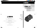
GBR 21
beacon receiver
© 1993-2000 GARMIN Corporation
GARMIN International, Inc.
1200 East 151st Street, Olathe, Kansas 66062, U.S.A.
GARMIN (Europe) Ltd.
Unit 5, The Quadrangle, Abbey Park Industrial Estate, Romsey, SO51 9AQ, U.K.
GARMIN (Asia) Corporation
No. 68, Jangshu 2nd Rd., Shijr, Taipei County, Taiwan
www.garmin.com
Part Number 190-00069-00 Rev. C
owner’s
manual
and
reference
guide
© 1993-2000 GARMIN Corporation
GARMIN International, Inc.
1200 East 151st Street, Olathe, Kansas 66062, U.S.A.
Tel. 913/397.8200 or 800/800.1020
Fax 913/397.8282
GARMIN (Europe) Ltd.
Unit 5, The Quadrangle, Abbey Park Industrial Estate, Romsey, SO51 9AQ, U.K.
Tel. 44/1794.519944
Fax 44/1794.519222
GARMIN (Asia) Corporation
No. 68, Jangshu 2nd Rd., Shijr, Taipei County, Taiwan
Tel. 886/02.2642.8999
Fax 886/02.2642.9099
All rights reserved. Except as expressly provided herein, no part of this manual may
be reproduced, copied, transmitted, disseminated, downloaded or stored in any
storage medium, for any purpose without prior written consent of GARMIN
Corporation. GARMIN Corporation hereby grants permission to download a single
copy of this manual onto a hard drive or other electronic storage medium to be
viewed for personal use, provided that such electronic or printed copy of this
manual contains the complete text of this copyright notice and provided further that
any unauthorized commercial distribution of this manual is strictly prohibited.
Information in this manual is subject to change without notice. GARMIN
Corporation reserves the right to change or improve its products and to make
changes in the content without obligation to notify any person or organization of
such changes. Visit the GARMIN website for current updates and supplemental
information concerning the use and operation of this and other GARMIN products.
Website address: www.garmin.com
GARMIN and GBR 21 are registered trademarks of GARMIN Corporation and may
not be used without the express permission of GARMIN Corporation.
January 2000
Part Number 190-00069-00 Rev. C
Printed in Taiwan
Introduction
Limited Warranty
GARMIN Corporation warrants this product to be free from defects in
materials and workmanship for one year from the date of purchase.
GARMIN will, at its sole option, repair or replace any components which
fail in normal use. Such repairs or replacement will be made at no charge to
the customer for parts or labor. The customer is, however, responsible for
any transportation costs. This warranty does not cover failures due to
abuse, misuse, accident or unauthorized alteration or repairs.
THE WARRANTIES AND REMEDIES CONTAINED HEREIN ARE
EXCLUSIVE AND IN LIEU OF ALL OTHER WARRANTIES EXPRESSED
OR IMPLIED, INCLUDING ANY LIABILITY ARISING UNDER WARRANTY OF MERCHANTABILITY OR FITNESS FOR A PARTICULAR
PURPOSE, STATUTORY OR OTHERWISE. THIS WARRANTY GIVES YOU
SPECIFIC LEGAL RIGHTS, WHICH MAY VARY FROM STATE TO STATE.
IN NO EVENT SHALL GARMIN BE LIABLE FOR ANY INCIDENTAL,
SPECIAL, INDIRECT OR CONSEQUENTIAL DAMAGES, WHETHER
RESULTING FROM THE USE, MISUSE OR INABILITY TO USE THIS
PRODUCT OR FROM DEFECTS IN THE PRODUCT. SOME STATES DO
NOT ALLOW THE EXCLUSIONS OF INCIDENTAL OR CONSEQUENTIAL DAMAGES, SO THE ABOVE LIMITATIONS MAY NOT APPLY TO
YOU.
To obtain warranty service, call the GARMIN Customer Service
department (913/397.8200) for a returned merchandise authorization
number. The unit should be securely packaged with the tracking number
clearly marked on the outside of the package, and sent freight prepaid and
insured to a GARMIN warranty service station. A copy of the original sales
receipt is required as the proof of purchase for warranty repairs. GARMIN
retains the exclusive right to repair or replace the unit or software or offer a
full refund of the purchase price at its sole discretion. SUCH REMEDY
SHALL BE YOUR SOLE AND EXCLUSIVE REMEDY FOR ANY BREACH
OF WARRANTY.
1
Introduction
Cautions
All differential beacon receivers decode correction data determined at
the beacon transmitter site via a GPS receiver(s). The GPS system is
operated by the government of the United States which is solely
responsible for their accuracy and maintenance. The DGPS beacon
transmitters are operated by the U.S. Coast Guard (or similar government agency in other countries) which is responsible for their accuracy
and maintenance. The Global Positioning System and the Differential
Global Positioning System are under development and are subject to
changes which could affect accuracy and performance of all DGPS
equipment. Although a DGPS system is a precision electronic
NAVigation AID (NAVAID), any NAVAID can be misused or misinterpreted, and therefore become unsafe. Use the DGPS system at your own
risk. To reduce this risk, carefully review and understand all aspects of
this Owner’s Manual and carefully compare indications from your GPS
receiver to all available navigation sources including the information
from other NAVAIDs, visual sightings, charts, etc. For safety, always
resolve any discrepancies before continuing navigation.
NOTE: This device complies with Part 15 of the FCC rules.
Operation of this device is subject to the following conditions: (1) This
device may not cause harmful interference, and (2) this device must
accept any interference received, including interference that may cause
undesired operation.
The GARMIN GBR 21 does not contain any user-serviceable parts.
Repairs should only be made by an authorized GARMIN service center.
Unauthorized repairs or modifications could void your warranty and
authority to operate this device under Part 15 regulations.
2
Introduction
Table of
Contents
Introduction
Limited Warranty........................................................1
Cautions .....................................................................2
Table of Contents .......................................................3
List of Figures ............................................................4
Overview
Capabilities & Package Contents................................5
Installation
Mounting the Receiver ............................................6-7
Mounting the Antenna ...............................................8
Connecting GBR and GPS ....................................9-11
Operation
Using the GBR 21 ...............................................11-13
Reference
DGPS: How It Works ..........................................13-14
Sources of Error ..................................................15-16
Troubleshooting Chart ........................................17-18
GBR 21 Specifications ..............................................19
Index ........................................................................20
Mounting Template .........................................................21
3
Introduction
List of
Figures
Installation
Figure 1: Mounting the Receiver............................................page 6
Figure 2: GBR 21 Cable Connections............................................7
Screen Example: GPS 12/12XL/48 Main Menu.............................8
Screen Example: GPS 12/12XL/48 Input/Output Settings.............8
Screen Example: GPS 12/12XL/48 Beacon Receiver Setup Page....9
Figure 3: Sample Wiring Diagram for GARMIN GPS units....10-11
Operation
Screen Example: GPSMAP Fixed Mount* Main Menu................12
Screen Example: GPSMAP Fixed Mount* Input/Output Page.....12
Reference
Figure 4: The DGPS System.........................................................13
Screen Example: GPSMAP Fixed Mount* Beacon Settings..........13
Figure 5: Shipboard DGPS System..............................................14
Screen Example: GPS Handheld** Main Menu...........................14
Screen Example: GPS Handheld** Interface Settings..................14
Screen Example: GPS Handheld** Beacon Settings....................15
Screen Example: GPS Handheld** Beacon Log Page...................15
Screen Example: Satellite Status Page.........................................17
Screen Example: “No Differential Position” Error.............................18
Mounting Template....................................................................21
*Screen examples apply to models 130/135/175/180/185/230/235
**Screen examples apply to models III/III+/12Map/NavTalk
4
Overview
Capabilities
The GBR 21 offers a host of powerful capabilities to
enhance the performance and accuracy of your GARMIN
GPS receiver:
• Performance— Single channel operation provides
high-sensitivity manual tuning throughout the
beacon broadcast band.
• Ease of Use— Operation is controlled using the
Beacon Receiver Setup and Beacon Log pages on
your GPS unit.
• Convenience— May be remotely mounted in an
out-of-the-way location. Receiver status information is displayed directly on the GPS unit.
• Low Power Consumption— Draws approximately 130 milliamps during normal operation.
• Interfaces — User-selectable operation for 4800 or
9600 baud.
• Accuracy— Improves position accuracy of GPS
unit to better than 10 meters (2 drms).
Package Contents
Your GARMIN GBR 21 package includes:
• GBR 21 unit
• Power/Data Cable
• Antenna coupler w/ 30’ cable & whip antenna
or GA 22/23 H-field beacon antenna w/ 30’ cable
• Owner’s Manual
• Beacon Reference Card
This package provides the materials required to
permanently install the GBR 21 and connect it to your
GARMIN GPS unit. In addition to supplying power to the
GBR 21, the power/data cable is used to interface the GBR
21 to the GPS unit. The receiver may be powered by an
external 10-18 VDC power source. Power to the receiver
should be controlled by an on/off switch (not included),
such as an accessory switch on the control console.
Capabilities &
Package Contents
The GBR 21 may be used with a
variety of GARMIN GPS
receivers. The list below
identifies most, but not all,
compatible models. If your GPS
receiver is not listed, you may
check with your GARMIN
dealer or contact GARMIN
product support at 1-800-8001020 to verify compatibility.
•GPS II/II+/III/III+/III Pilot
•GPS eMap/eTrex/NavTalk
•GPS StreetPilot/ColorMap
•GPS 12/12XL/12CX/12Map
•GPS 38/40
•GPS 45/45XL/48
•GPS 50/75
•GPS 65
•GPS 89/90/92/95
•GPS 120/125
•GPSCOM 170/190
•GPSMAP 130/135/180/185
•GPSMAP 162/168
•GPSMAP 175/195/295
•GPSMAP 210/220/215/225
•GPSMAP 230/235
5
Installation
Mounting the Receiver
Mounting the
Receiver
Please read through these instructions thoroughly before
attempting installation. Make sure you completely understand
these instructions before you begin. When in doubt, seek
professional assistance.
The receiver may be mounted at a remote location,
under the dash or behind a panel. However, you may
wish to mount the receiver at a location that allows easy
viewing of the LED status light for immediate indication
of receiver status.
The following items are required to complete the
installation of your GBR 21:
• Antenna mount (standard 1-inch, 14 threads per
inch)
• Hardware (to secure the GBR 21)
• On/off switch (to control power to the GBR 21)
It is recommended that the system be temporarily
hooked up with the wiring and unit placement
approximating the desired final installation. Then check
operation with potential local interfering equipment
turned on and off. For example, other electronic
equipment, fan motors, engine ignition, alternators or
generators can be sources of interference.
INSTALLATION NOTES
Recommended Screw/Bolt Diameter: #4 or #6
Material: Stainless Steel
Length: Select per your installation
Locknuts or lockwashers are recommended.
Hardware shown is for example purposes only.
6
Figure 1: Mounting the Receiver
Installation
If a problem is found, try altering the location of the
unit or wiring. Often moving the antenna a few feet away
from the source of interference will solve the problem.
When a suitable configuration is found, a permanent
installation should be made.
The GBR 21 may be mounted on any flat surface.
Select the mounting location according to your
preferences— either an out-of-the-way location (such as
under the dash) or at an accessible location where the
LED status light will be visible. Keep in mind that from
this mounting location cables will be routed to the
antenna and to the GPS unit.
Mounting the
Receiver
1. Drill the mounting holes (4) for the GBR 21
according to the mounting hardware that will be
used. Mounting hardware is not included with the
GBR 21. You should select the mounting hardware
suitable for your installation. Stainless steel (#4 or
#6 diameter) hardware is recommended. A
mounting template is provided inside the back cover
of this manual.
2. Mount the GBR 21 at this location using the
selected hardware.
3. Connect the power/data cable to the GBR 21,
observing the proper polarity as indicated by the
notch in the connector.
BNC Connector
Power/Data Connector
Alignment Notch
Figure 2: GBR 21 Cable Connections
4. Connect the RED wire from the power/data cable to
an accessory switch on the dash. If an accessory
switch is not available, a standard SPST switch may
be used (not included).
5. Connect the other end of the accessory switch to
the ship’s positive 10-18 Volt DC power source.
6. Connect the BLACK wire from the power/data cable
to vessel ground (or the negative terminal of the
ship’s 10-18 Volt DC power source).
7
Installation
Mounting the Antenna
Mounting the
Antenna
The Interface Setup Page
may be selected from the
Main Menu on the GPS 12/
12XL/48. For additional
instructions, see the owner’s
manual for your GPS
receiver.
The supplied antenna coupler fits a standard 1-inch
antenna mount (not included). Like the receiver, the
antenna should be placed away from all sources of
interference. As a general rule, mount the antenna at least
three feet from all other antennas and the vessel’s electrical
system components (alternator/ignition system). Position
the antenna so that the clearest view in all directions is
obtained. The antenna coupler is supplied with 30 feet of
RG58 cable attached. When routing the cable to the GBR
21, observe the same precautions followed when choosing
mounting locations for the receiver and the antenna: Avoid
routing the cable near the vessel’s alternator or ignition
system components.
A ground strap is attached to the antenna coupler,
except on the GA 22/23 H-field antennas. For proper
operation, the ground strap must be connected to a vessel
(earth) ground. Do not ground the coupler to the electrical
system. If the coupler is not adequately grounded, the
beacon signal may be too weak for the GBR 21 to provide
reliable correction data.
Note: The GA 22/23 H-field antennas do not
require grounding.
1. Secure the antenna mount at the desired mounting
location.
2. Thread the antenna coupler/GA 23 onto the antenna
mount and hand tighten until snug. Do not over
tighten. Thread whip antenna onto coupler.
3. Connect the antenna coupler’s ground strap to a
vessel (earth) ground. A ground connection can
usually be made by connecting to a thru-hull fitting,
engine block, dynaplate or body of a metal vehicle.
From the Interface Page,
select ‘RTCM/NMEA’ and
‘NMEA 0183 2.0’ to properly
communicate with the
GBR 21.
4. Route the antenna cable to the GBR 21. Excess cable
should be coiled together and secured in an
inconspicuous location. Modifications to the DGPS
antenna cable could result in undesired operation of
the GBR 21.
5. Connect the antenna cable to the BNC connector
on the GBR 21.
8
Installation
Connecting the GBR 21 To Your GPS Unit
The final step in installing the GBR 21 is to connect
the receiver’s DATA IN, DATA OUT and GROUND
(Return) lines to your GPS unit. The GBR 21 is designed
to transmit/receive data at 4800 or 9600 baud (bits per
second). The receiver defaults to 4800 baud, which is
suitable for use with all GARMIN GPS receivers. The
9600 baud option is provided to allow the receiver to be
used with some newer models and other manufacturer’s
GPS units.
Two ground wires are provided on the power/data
cable. For reliable communication, it is essential that the
GBR 21 and the GPS unit share the same ground. This
ground connection acts as the (current) Return line. You
may connect either the YELLOW wire or the BLACK wire
from the power/data cable to the ground wire of the GPS
unit
NOTE: Some non-GARMIN GPS units may have a
separate data line labeled “RETURN”, “DATA GROUND”
or “DATA -”. If one of these lines exist, connect the
YELLOW wire from the power/data cable to it.
Connecting
GBR and GPS
Use the Beacon Receiver
Setup Page to enter the
beacon operating frequency
and bit rate for the nearest
DGPS beacon site. This
information is automatically
transferred to the GBR 21.
1. Connect the BLUE wire from the GBR 21’s power/
data cable to the DATA INPUT line of the GPS unit.
2. Connect the BROWN wire from the power/data
cable to the DATA OUTPUT line of the GPS unit.
3. Connect the YELLOW (or BLACK) wire from the
power/data cable to the GROUND wire of the GPS
unit. If the BLACK wire is already connected to the
same ground terminal as the GPS unit, no additional
connection is required (unless a separate RETURN
line is provided by the GPS unit).
4. If 9600 baud operation is required, connect the
WHITE and GREEN power/data cable wires together.
For 4800 baud operation (default), leave these wires
disconnected.
9
Installation
Connecting
GBR and GPS
UNITS WITH
7 PIN PLUG
4
3
10-18 VDC
GBR 21
(1) RED: POWER INPUT
(1) RED: 10-18 VDC
(2) BLACK: GROUND
(2) BLACK: GROUND
(3) BLUE: DATA OUT
(3) BLUE: DATA OUT
5
(4) BROWN: DATA IN
(4) BROWN: DATA IN
2
6
1
7
(5) WHITE: NOT USED
(5) WHITE: BAUD SELECT IN
(6) GREEN: NOT USED
(7) YELLOW: ALARM
(6) GREEN: BAUD SELECT OUT
(7) YELLOW : GROUND
JUMPER THESE TOGETHER FOR 9600 BAUD.
LEAVE THESE UNCONNECTED FOR 4800 BAUD.
UNITS WITH
13 PIN PLUG
1
2
10-18 VDC
GBR 21
(2) RED: POWER INPUT
(1) RED: 10-18 VDC
(1) BLACK: GROUND
(2) BLACK: GROUND
(4) BLUE: DATA OUT
(3) BLUE: DATA OUT
(4) BROWN: DATA IN
(5) BROWN: DATA IN
(6) YELLOW: ALARM
(5) WHITE: BAUD SELECT IN
(3, 7-13) NOT USED
(6) GREEN: BAUD SELECT OUT
(7) YELLOW
JUMPER THESE TOGETHER FOR 9600 BAUD.
LEAVE THESE UNCONNECTED FOR 4800 BAUD.
13
UNITS WITH
6 PIN PLUG
10-18 VDC
GBR 21
(1) RED: 10-18 VDC
(1) RED: POWER INPUT
(2) BLACK: GROUND
(2) BLACK: GROUND
(3) BLUE: ALARM
(3) BLUE: DATA OUT
(4) BROWN: DATA OUT
(4) BROWN: DATA IN
(5) WHITE: DATA IN
(5) WHITE: BAUD SELECT IN
(6) RED/BLK: NOT USED
(6) GREEN: BAUD SELECT OUT
(7) YELLOW
JUMPER THESE TOGETHER FOR 9600 BAUD.
LEAVE THESE UNCONNECTED FOR 4800 BAUD.
UNITS WITH
4 PIN ROUND PLUG
1
4
3
10-18 VDC
GBR 21
(1) RED: POWER INPUT
(1) RED: 10-18 VDC
(2) BLACK: GROUND
(2) BLACK: GROUND
(3) BROWN: DATA OUT
(3) BLUE: DATA OUT
(4) WHITE: DATA IN
(4) BROWN: DATA IN
(5) WHITE: BAUD SELECT IN
2
(6) GREEN: BAUD SELECT OUT
(7) YELLOW
JUMPER THESE TOGETHER FOR 9600 BAUD.
LEAVE THESE UNCONNECTED FOR 4800 BAUD.
10
Figure 3: Sample Wiring to GARMIN GPS Units
Operation
Using the
GBR 21
UNITS WITH
18 PIN PLUG
2
1
3
6
10-18 VDC
GBR 21
(15) RED: POWER INPUT
(1) RED: 10-18 VDC
(18) BLACK: GROUND
(2) BLACK: GROUND
(17) BLUE: DATA OUT
(3) BLUE: DATA OUT
(4) BROWN: DATA IN
(16) BROWN: DATA IN
11
7
(11) YELLOW: ALARM
(5) WHITE: BAUD SELECT IN
15
12
(1-10,12-14) NOT USED
(6) GREEN: BAUD SELECT OUT
18
(7) YELLOW : GROUND
16
JUMPER THESE TOGETHER FOR 9600 BAUD.
LEAVE THESE UNCONNECTED FOR 4800 BAUD.
UNITS WITH 4 PIN,
RECTANGLE PLUG
10-18 VDC
GBR 21
(1) RED: 10-18 VDC
(4) BLACK: GROUND
(2) BLACK: GROUND
(3) WHITE: DATA OUT
(2) GREEN: DATA IN
(3) BLUE: DATA OUT
(4) BROWN: DATA IN
(5) WHITE: BAUD SELECT IN
(Not used)1
2
3
4
(6) GREEN: BAUD SELECT OUT
(7) YELLOW
JUMPER THESE TOGETHER FOR 9600 BAUD.
LEAVE THESE UNCONNECTED FOR 4800 BAUD.
Figure 3 (cont.): Sample Wiring to GARMIN GPS Units
Using the GBR 21
When using the GBR 21, all tuning/operation
functions are controlled by the GPS unit. Your GARMIN
GPS unit provides a Beacon Receiver Setup Page and, in
some cases, Beacon Log Page for this purpose. The
operating instructions provided below are generalized to
cover several different GARMIN models. For additional
information on operating your GPS unit with the GBR 21,
refer to the owner’s manual for your GPS unit.
1. Turn the power on to the GBR 21. The LED
status light will flash indicating power has been
applied, but no beacon signal is being received.
2. Turn the GPS unit on.
3. From the Interface Setup Page, select an RTCM
input. If a baud rate selection is also provided,
specify 4800 or 9600 baud, as appropriate. On
GARMIN GPS units, RTCM input/NMEA 0183
output should be selected. The baud rate will be
set to 4800. If additional devices, such as an
11
Operation
Using the
GBR 21
autopilot or plotter, are connected to the GPS
unit, they must be set to work with NMEA 0183
as well.
(Note: On some newer model Garmin GPS
receivers, you may set the interface to
“Garmin Bcn Rcvr”. There is also a scan option
which will automatically scan for a DGPS
frequency and bit rate. Please refer to your GPS
owner’s manual for using this function. If this
setting is used, you may skip step 4.)
4. From the Beacon Receiver Setup Page, enter the
“Tuned To:” frequency and the “Bit Rate” for the
nearest DGPS beacon transmitter. (Refer to the
Beacon Reference Card for this information.)
5. Once the frequency and bit rate have been entered, “Tuning” will be displayed at the bottom
of the page.
The Main Menu Page on the
GPSMAP 130/135/175/
180/185/230/235. Select
‘Input/Output’ to make the
desired interface settings.
6. If the beacon signal is received by the GBR 21,
the “SNR” field will display a signal-to-noise ratio
and “Receiving” will appear at the bottom of the
page. The SNR scale ranges from zero (no reception) to 30 (best reception). The LED status light
on the receiver will change from flashing to
constantly on, indicating the signal is being
received.
If the beacon signal is received, but no DGPS
correction data is included, the message “No
Data” will appear at the bottom of the page. The
LED status light on the receiver will continue to
flash.
If no beacon signal is received, the “SNR” field
will remain blank, “No Status” will appear at the
bottom of the page, and the LED status light will
continue to flash.
From the Input/Output
Settings Page, select ‘RTCM
In/NMEA Out’ to properly
interface with the GBR 21.
12
7. To select another beacon transmitter, enter a new
frequency and bit rate.
8. Some Garmin units have a list of the last five
beacon frequencies used on the Beacon Log
Page. As an alternative to reentering frequency
and bit rate information each time you use the
GBR 21, you may select a beacon from this list.
(NOTE: The Beacon Receiver Setup Page will
Reference
automatically default to the last beacon
transmitter used each time the GPS unit is turned
on.)
9. Select the Satellite Bar Graph Page. A “D” will
appear at the bottom of the signal strength bar
for each satellite with a corresponding differential correction or “3D Differential” will be
displayed at the top of the satellite page. This
page is useful for determining the quality of
differential coverage available. (Remember, the
more satellites with corresponding differential
corrections, the more accurate your position will
be.)
DGPS:
How It Works
DGPS: How It Works
Differential GPS (DGPS) is a technique used to
improve the accuracy of the Global Positioning System.
DGPS reduces the effects of Selective Availability(SA),
ionospheric variations and can improve position accuracy
to better than 10 meters.
AL
GN
S
SI
GPS
GP
After entering the beacon’s
operating frequency, set the
bit rate as indicated on the
Beacon Reference Card.
Beacon information is also
available from the other
sources listed on the card.
NAL
SIG
CO
RR
DA EC
GPS RECEIVER
TA TI
O
N
STATION AND
DGPS TRANSMITTER
DGPS
(CORR
ECTIO
N) SIG
NA
L
SHIPBOARD GPS AND
DGPS RECEIVERS
Figure 4: The DGPS System
A DGPS system consists of the following:
• DGPS Beacon Transmitter and GPS Receiver at
a known location
• Shipboard DGPS Beacon Receiver
• Shipboard GPS Receiver (DGPS capable)
• GPS Satellites
13
Reference
DGPS:
How It Works
The Main Menu Page on the
GPS III/III+/12Map/
Navtalk. Select ‘Setup’ to
make the desired interface
settings.
The DGPS Beacon Transmitter is placed at a known
location (i.e., the exact position of the site has been
previously determined). At the beacon transmitter site,
the GPS satellites are monitored using a GPS receiver.
This receiver is equipped to calculate corrections for each
satellite received. The correction is the difference between
the distance to the satellite (from the beacon site) as
measured by the GPS receiver, and the actual distance to
the satellite based on the known location of the beacon
site. These corrections are communicated to the users
GPS set through the DGPS Beacon Station and the
GBR 21. The users GPS set then uses the corrections to
remove errors from its measurements. Satellites received
by the shipboard GPS receiver, but not by the GPS
receiver at the beacon transmitter site, will not have
corresponding corrections. When three or more satellites
received by the shipboard GPS receiver have corresponding corrections, the result is a highly accurate position
reading. The more satellites with corrections, the more
accurate the position.
DGPS BEACON
SIGNAL IN
GPS SIGNAL IN
STANDARD
ANTENNA
COUPLER
GA 22/23 H-FIELD
BEACON ANTENNA
GA-29 GPS
ANTENNA
OR
BEACON
RECEIVER
GPS
RECEIVER
CORRECTION DATA
(RTCM SC-104)
Figure 5: Shipboard DGPS System
From the Interface Page,
select ‘RTCM/NMEA’ to
properly interface with the
GBR 21.
14
The GBR 21 receives RTCM-SC-104 format signals
from ground based DGPS Beacon Stations operating in
the 283.5 kHz to 325.0 kHz frequency band, with MSK
modulation and data rates of 25,50,100, or 200 bits per
second. These stations are typically operated by
government agencies such as the U.S. Coast Guard.
Reference
Individual stations vary and the user may wish to
verify the suitability of the signal for the intended
application with the station operator. The station power is
normally set to provide a usable range somewhere near
300 km. Other factors such as local interference,
lightning, time of day and season, and if the path to the
station is over ground or water, and antenna selection or
installation affect the usable signal range.
Sources of
Error
Sources of Error
Using a DGPS Beacon Receiver with your existing
GPS Receiver can provide substantial improvements in
accuracy; however, there may be occasions when the best
possible accuracy will not occur. Several factors, which
you should be aware of, can contribute to a degraded
DGPS accuracy.
Loss of DGPS Beacon Signal—Obviously, the lack
of DGPS correction data will result in reduced accuracy.
Accuracy will be the same as if no beacon receiver was
being used. Several conditions can cause a loss of the
beacon signal:
• Poor data or ground connections between receiver
and the GPS receiver can result in intermittent or
nonexistent correction data.
• The range of a DGPS beacon transmitter (see the
accompanying Beacon Reference Card) is typically
a few hundred miles, or less. Beyond this range,
the beacon signal cannot be reliably received.
• Interference to the beacon signal can be experienced during periods of thunderstorm activity.
Other sources of static interference, such as
alternator motors and ignition systems, can also
affect signal reception. Alternator/ignition
interference can be minimized through proper
shielding of the ship’s wiring, by using an EMI/RFI
filter, and by mounting the beacon receiver’s
antenna away from these sources of interference.
After entering the beacon’s
operating frequency, set the
bit rate as indicated on the
Beacon Reference Card.
Beacon information is also
available from the other
sources listed on the card.
The Beacon Log Page lists the
last five beacon frequencies
used. As an alternative to
retyping the frequency and bit
rate each time, you may select
a beacon from this list.
15
Reference
Sources of
Error
16
Multipath— Multipath error occurs when the GPS
signal is reflected before it reaches the GPS receiver. The
reflected signal takes slightly longer to reach the GPS
receiver than a non-reflected signal. This added time delay
results in position error. (The distance to each satellite is
calculated based upon the time it takes the GPS signal to
reach the GPS receiver.) Multipath error can be minimized
by mounting the GPS antenna at a location which
minimizes the potential for reflected signals. Generally,
the GPS antenna should be mounted on a large, flat
horizontal surface and away from any vertical structure
(cabin walls, large mast, etc.) which could reflect the GPS
signal.
Number of Satellites Visible— As previously
stated, the number of satellites available can affect
position accuracy. To apply the corrections provided for
the satellites received at the beacon transmitter station, the
same satellites (at least in part) must be received by your
GPS receiver. And, certainly, if there aren’t enough
satellites to determine a GPS position, there aren’t enough
satellites to calculate a DGPS position.
Satellite Geometry— A minimum of 4 satellites are
required to determine a 3D position. At times, additional
satellites are required due to their placement with respect
to each other. This relative placement is referred to as
“satellite geometry”. Ideal satellite geometry exists when
the satellites are located at wide angles with respect to
each other. When satellites are located in a line, satellite
geometry is considered poor.
This same requirement applies to DGPS. If
corrections are available for four different satellites, but
they are all located in the same general area or in a line,
the DGPS corrections will be minimal. However, if the
same four satellites are placed farther apart, in several very
different directions from our position, the corrections will
have a much greater effect and the position accuracy will
be greatly improved.
Reference
Problem
Possible Cause
1) Receiver will not
power on (No LED)
Power switch/wiring faulty.
Fuse/breaker blown (if used).
2) LED status light
flashing
RTCM data not being received
from broadcast site.
Wrong bit rate selected on GPS
unit.
Wrong frequency selected on
GPS unit.
GBR 21 not wired properly with
GPS unit. Check wiring.
Also refer to Troubleshooting
problems 6 and 7.
3) “No DGPS Position” Not enough data is available to
displayed on GPS unit compute a DGPS position.
Please refer to Troubleshooting
problems 6 and 7.
Beacon receiver is improperly
4) “No RTCM Input”
displayed on GPS unit connected or baud rates do not
match.
Please refer to Troubleshooting
problems 6 and 7.
5) “RTCM Input
Failed” displayed on
GPS unit
Troubleshooting
Chart
The receiver status indication
at the top left of the Satellite
Status Page will indicate ‘3D
Diff’ or ‘2D Diff’ when
differential corrections are
available. A ‘D’ appears at
the bottom of the signal
strength bar for each satellite
with a corresponding
differential correction.
Intermittent connection between
GBR 21 and GPS unit. Check
wiring and/or beacon antenna
connections.
Interference from ship’s electrical
system, thunderstorm activity, or
another source is preventing
signal lock-on.
Also refer to Troubleshooting
problems 6 and 7.
17
Reference
Troubleshooting
Chart
If the ‘No Differential GPS
Position’ message is displayed
on your GPS receiver,
correction data may not be
available. This may be due to a
missing or weak beacon signal,
not enough GPS satellites or
bad wiring connection between
the GBR 21 and GPS.
Problem
6) GPS interface
status screen displays
“No data” or “No
Signal”
Wrong frequency or bit rate
selected on GPS unit.
Antenna coupler not securely
grounded. Check ground strap.
Beacon transmitter not
transmitting correction data.
7) GPS interface
status screen displays
“None”, “No Status”
or “Check Wiring”
GBR 21 not wired properly with
GPS unit. Check wiring.
No power to GBR 21. See
Troubleshooting problem 1.
Problem with DGPS antenna
grounding or damage.
Baud rates do not match.
Beacon transmitter out of range.
Try a different station.
8) Beacon signal weak Antenna coupler not securely
grounded. Check ground strap.
or not received.
Interference from ship’s
electrical system, thunderstorm
activity, or another source is
inhibiting signal lock on.
Also refer to Troubleshooting
problems 6 and 7.
9) Accuracy not as
expected
If either ‘No Status’, ‘None’, or
‘Check Wiring’ messages
appear (depending upon model
of GPS) see Troubleshooting
problem number 7.
18
Possible Cause
Poor satellite geometry
coverage exists.
Interference to GPS antenna
and/or beacon antenna exists.
Portable antenna being used
on GPS unit. Use remote
antenna.
Multipath signals being
received by GPS unit.
Too far from DGPS transmiter
or not tuned to closest station.
Reference
Physical
Size:
5.2”L x 3.6”W x 1.5”H
(132mm x 91mm x 38mm)
Weight:
6.8 ounces (0.193 kg)
GBR 21
Specifications
Power
Voltage:
10 - 18 volts DC using supplied
power/data cable
Current Drain:
130 mA
Signal Processing
Frequency Range:
283.5 - 325.0 kHz
Minimum Signal:
10 µV
Acquisition Time:
15 seconds
Data Processing
Demodulation:
MSK (Minimum Shift Keying)
MSK Bit Rates:
25, 50, 100, 200 bps
Interfaces
Input:
RS-232 or NMEA 0183
4800 or 9600 baud
(jumper selectable)
Input Sentences:
Binary (Magnavox),
$PSLIB (Starlink)
Output:
RS-232
4800 or 9600 baud
(jumper selectable)
Output Sentence:
RTCM SC-104
(6 of 8 bit format)
Antenna Coupler
Diameter:
1.6” (41mm) base, .6” (15mm) top
Height:
4.8” (122mm) without antenna
16.8” (427mm) with antenna
19
Reference
Index
A
Antenna.............................................5, 7
Antenna coupler.................................5, 8
Antenna mount..................................6, 8
B
Baud rate...............................................9
Beacon Log Page..................................12
Beacon Range.......................................15
Beacon Receiver..............................13-14
Beacon Receiver Setup Page............11-12
Beacon Station................................14-15
Beacon Transmitter.........................13-14
C
Capabilities............................................5
Cautions................................................2
Compatibility.........................................5
Connections, Wiring.........................9-11
Contents, Package..................................5
D
DGPS System..................................13-14
E
Interference..............................................8
L
LED Status Light....................................12
LED Status light.....................................11
M
Mounting Template................................21
Mounting the Antenna.............................8
Mounting the Receiver..............................6
O
On/Off Switch......................................5, 7
Operation.........................................11-12
P
Package Contents.....................................5
Power/Data Cable.....................................5
Power/data cable..................................7, 9
R
RTCM-SC-104 format............................14
S
F
Satellite Bar Graph Page.........................13
Sources of Error................................15-16
Specifications.........................................19
Frequencies...................................12, 14
T
Error, Sources of.............................15-16
G
Ground strap.........................................8
I
Installation, Antenna..............................8
Installation, Receiver...........................6-7
Interface Setup Page.......................11-12
20
Table of Contents.....................................3
Template, Mounting..............................21
Troubleshooting...............................17-18
W
Warranty Information.............................1
Wiring Conncetions..............................10
Wiring Connections...........................9, 11
Reference
Template
Mounting
Template
NOTES:
Select fastener type/length per
your installation.
4.752" (120.70mm)
Maximum Hole Diameter =
0.145" (3.68mm)
3.359" (85.30mm)
21
GBR 21
beacon receiver
© 1993-2000 GARMIN Corporation
GARMIN International, Inc.
1200 East 151st Street, Olathe, Kansas 66062, U.S.A.
GARMIN (Europe) Ltd.
Unit 5, The Quadrangle, Abbey Park Industrial Estate, Romsey, SO51 9AQ, U.K.
GARMIN (Asia) Corporation
No. 68, Jangshu 2nd Rd., Shijr, Taipei County, Taiwan
www.garmin.com
Part Number 190-00069-00 Rev. C
owner’s
manual
and
reference
guide