1
GPS 35 LP TracPak TM
GPS SMART ANTENNA
TECHNICAL SPECIFICATION
Models:
GPS35-LVC
GPS35-LVS
GPS35-HVS
____________________________________________________________
GARMIN · 1200 E. 151st Street · Olathe, Kansas 66062 · (913) 397-8200 · (913) 397-8282 FAX
© 2000 GARMIN Corporation, 1200 E. 151st Street, Olathe, KS 66062
All rights reserved. No part of this manual may be reproduced or transmitted in any form or by any means,
electronic or mechanical, including photocopying and recording, for any purpose without the express written
permission of GARMIN.
Information in this document is subject to change without notice. GARMIN reserves the right to change or improve
their products and to make changes in the content without obligation to notify any person or organization of such
changes or improvements.
March, 2000
190-00148-00 Rev. E
ii
CAUTION
The GPS system is operated by the government of the United States which is solely responsible for its
accuracy and maintenance. Although the GPS 35LP is a precision electronic NAVigation AID (NAVAID),
any NAVAID can be misused or misinterpreted, and therefore become unsafe. Use the GPS 35LP at
your own risk. To reduce the risk, carefully review and understand all aspects of this Technical Manual
before using the GPS 35LP. When in actual use, carefully compare indications from the GPS 35LP to all
available navigation sources including the information from other NAVAIDs, visual sightings, charts, etc.
For safety, always resolve any discrepancies before continuing navigation.
NOTE
This device has been tested and found to comply with the limits for a Class B digital device, pursuant to
Part 15 of the FCC Rules. Operation is subject to the following two conditions: (1) This device may not
cause harmful interference, and (2) this device must accept any interference received, including
interference that may cause undesired operation.
This device generates, uses and can radiate radio frequency energy and, if not installed and used in
accordance with the instructions, may cause harmful interference to radio communications. However,
there is no guarantee that interference will not occur in a particular installation. If this device does cause
harmful interference to radio or television reception, which can be determined by turning the device off
and on, you are encouraged to try to correct the interference by one or more of the following measures:
· Reorient or relocate the receiving antenna.
· Increase the separation between this device and the receiver.
· Connect this device to an outlet on a different circuit than that to which the receiver is connected.
· Consult the dealer or an experienced radio/TV technician for help.
This device contains no user-serviceable parts. Repairs should only be performed by an authorized
GARMIN service center. Unauthorized repairs or modifications to this device could void your warranty
and your authority to operate this device under Part 15 regulations.
iii
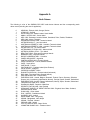
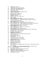
TABLE OF CONTENTS
1.
Introduction
1.1
Overview
1.2
Features
1.3
Naming Conventions
1.4
Technical Specifications
1.5
Application
1
1
1
2
2
4
2.
Operational Characteristics
2.1
Self Test
2.2
Initialization
2.3
Navigation
2.4
Satellite Data Collection
5
5
5
5
6
3.
Hardware Interface
3.1
Mechanical Dimensions
3.2
Mounting Configurations and Options
3.3
Connection Wiring Description
8
8
9
13
4.
Software Interface
4.1
NMEA Received Sentences
4.2
NMEA Transmitted Sentences
4.3
Baud Rate Selection
4.4
One-Pulse-Per-Second Output
4.5
RTCM Received Data
14
14
18
23
23
23
A.
B.
C.
Earth Datums
GPS 35LP Evaluation Kits
Phase Data Output
24
27
29
iv
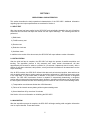
SECTION 1
INTRODUCTION
1.1 OVERVIEW
The GARMIN GPS 35LP is a complete GPS receiver, including an embedded antenna, designed for a
broad spectrum of OEM (Original Equipment Manufacturer) system applications. Based on the proven
technology found in other GARMIN 12 channel GPS receivers, the GPS 35LP will track up to 12
satellites at a time while providing fast time-to-first-fix, one second navigation updates and low power
consumption. Its far reaching capability meets the sensitivity requirements of land navigation as well as
the dynamics requirements of high performance aircraft.
The GPS 35LP design utilizes the latest technology and high level circuit integration to achieve superior
performance while minimizing space and power requirements. All critical components of the system
including the RF/IF receiver hardware and the digital baseband are designed and manufactured by
GARMIN to ensure the quality and capability of the GPS 35LP. This hardware capability combined with
software intelligence makes the GPS 35LP easy to integrate and use.
The GPS 35LP is designed to withstand rugged operating conditions and is completely water resistant.
The GPS 35LP is a complete GPS receiver that requires minimal additional components be supplied by
an OEM or system integrator. A minimum system must provide the GPS 35LP with a source of power
and a clear view of the GPS satellites. The system may communicate with the GPS 35LP via a choice of
two RS-232 compatible full duplex communication channels (-xVS series), or two full duplex CMOS
channels (-xVC series). Internal memory backup allows the GPS 35LP to retain critical data such as
satellite orbital parameters, last position, date and time. End user interfaces such as keyboards and
displays are added by the application designer.
1.2
FEATURES
The GPS 35LP provides a host of features that make it easy to integrate and use.
1) Full navigation accuracy provided by Standard Positioning Service (SPS)
2) Compact design ideal for applications with minimal space
3) High performance receiver tracks up to 12 satellites while providing fast first fix and low power
consumption
4) Differential capability utilizes real-time RTCM corrections producing 3-10 meter position accuracy
5) Internal clock and memory are sustained by a rechargeable memory backup battery. The battery
recharges during normal operation.
6) User initialization is not required
7) Navigation mode (2D or 3D) may be configured by the user
8) Two communication channels and user selectable baud rates allow maximum interface capability
and flexibility
9) Highly accurate one-pulse-per-second output for precise timing measurements. Pulse width is
configurable in 20 msec increments from 20 msec to 980 msec.
1
10) Binary Format Phase Data Output on TXD2
11) Flexible input voltage levels of 3.6Vdc to 6.0Vdc with overvoltage protection in the -LVx versions,
and 6.0Vdc to 40Vdc in the -HVx versions.
12) FLASH based program memory. New software revisions upgradeable through serial interface.
1.3 Naming Conventions
The GPS 35LP Series TrackPack™ receivers are delineated with a three letter extension to designate
the operating voltage range and the serial data voltage specification.
High Voltage - GPS35-HVx designation indicates that the unit will accept a high input voltage. The
internal switching regulator will operate from a 6VDC to 40VDC unregulated supply.
Low Voltage - GPS35-LVx designation indicates that the unit is designed to operated from a low
voltage 3.6VDC to 6.0VDC supply. Operation at about 4VDC is the most power efficient mode of
operation for the GPS35LP receiver. The unit is protected if a high voltage is inadvertently applied
to the input.
RS-232 Serial Data - GPS35-xVS designation means that the two bi-directional serial data ports
are true RS-232 ports conforming to the RS-232E standard.
CMOS Serial Data - GPS35-xVC designation means that the two bi-directional serial data ports
use CMOS output buffers. The input buffers will accept either CMOS(TTL) voltage levels or RS232 voltage levels. This configuration is adequate for communicating directly with serial devices
over short cable lengths (less than 20 meters).
1.4 TECHNICAL SPECIFICATIONS
Specifications are subject to change without notice.
1.4.1
Physical Characteristics
1) Single construction integrated antenna/receiver.
2) Weight: 4.4 oz, (124.5 g), not including cable
3) Size: 2.230" (w) x 3.796" (l) x 1.047" (h), (56.64 mm x 96.42 mm x 26.60 mm)
1.4.2
Environmental Characteristics
1) Operating temperature: -30°C to +85°C (internal temperature)
2) Storage temperature: -40°C to +90°C
1.4.3 Electrical Characteristics
1) Input voltage: +3.6VDC to 6.0VDC regulated, 150mV ripple -LVx versions.
+6.0VDC to 40VDC unregulated -HVx version.
2
2) Input current: 120 mA typical 140 mA max -LVx versions, 20 mA while in power down.
870mW typical 1000mW max -HVx version, 300uA while in power down.
3) Backup power: 3V Rechargeable Lithium cell battery, up to 6 month charge.
4) Power Down Input: 2.7V threshold
1.4.4 Performance
1) Tracks up to 12 satellites (up to 11 with PPS active)
2) Update rate: 1 second
3) Acquisition time
- 15 seconds warm (all data known)
- 45 seconds cold (initial position, time and
almanac known, ephemeris unknown)
- 5.0 minutes AutoLocate TM (almanac known,
initial position and time unknown)
- 5 minutes search the sky (no data known)
4) Position accuracy:
Differential GPS (DGPS): 5 meters RMS
Non-differential GPS: 15 meters RMS (100 meters with Selective Availability on)
5) Velocity accuracy: 0.2 m/s RMS steady state (subject to Selective Availability)
6) Dynamics: 999 knots velocity, 6g dynamics
7) One-pulse-per-second accuracy: +/-1 microsecond at rising edge of PPS pulse (subject to Selective
Availability)
1.4.5
Interfaces
1) Dual channel CMOS/TTL level (-xVC versions) or RS-232 compatible level (-xVS versions), with
user selectable baud rate (300, 600,1200, 2400, 4800, 9600, 19200)
2) NMEA 0183 Version 2.0 ASCII output (GPALM, GPGGA, GPGSA, GPGSV, GPRMC, GPVTG,
PGRME, PGRMT, PGRMV, PGRMF, LCGLL, LCVTG)
Inputs
- Initial position, date and time (not required)
- Earth datum and differential mode configuration command, PPS Enable, almanac
Outputs
- Position, velocity and time
- Receiver and satellite status
- Differential Reference Station ID and RTCM Data age
- Geometry and error estimates
3) Real-time Differential Correction input (RTCM SC-104 message types 1,2,3 and 9)
3
4) One-pulse-per-second timing output
5) Binary Format Phase Data
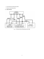
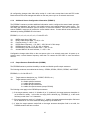
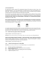
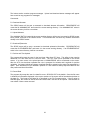
1.5 APPLICATION
Fig. 1, TYPICAL APPLICATION ARCHITECTURE
4
SECTION 2
OPERATIONAL CHARACTERISTICS
This section describes the basic operational characteristics of the GPS 35LP. Additional information
regarding input and output specifications are contained in Section 4.
2.1 SELF TEST
After input power has been applied to the GPS 35LP and periodically thereafter, the unit will perform
critical self test functions and report the results over the output channel(s). The following tests will be
performed:
1) RAM check
2) FLASH memory test
3) Receiver test
4) Real-time clock test
5) Oscillator check
In addition to the results of the above tests, the GPS 35LP will report software version information.
2.2 INITIALIZATION
After the initial self test is complete, the GPS 35LP will begin the process of satellite acquisition and
tracking. The acquisition process is fully automatic and, under normal circumstances, will take
approximately 45 seconds to achieve a position fix (15 seconds if ephemeris data is known). After a
position fix has been calculated, valid position, velocity and time information will be transmitted over the
output channel(s).
Like all GPS receivers, the GPS 35LP utilizes initial data such as last stored position, date and time as
well as satellite orbital data to achieve maximum acquisition performance. If significant inaccuracy exists
in the initial data, or if the orbital data is obsolete, it may take 5.0 minutes to achieve a navigation
solution. The GPS 35LP AutolocateTM feature is capable of automatically determining a navigation
solution without intervention from the host system. However, acquisition performance can be improved if
the host system initializes the GPS 35LP following the occurrence of one or more of the following events:
1) Transportation over distances further than 1500 kilometers
2) Failure of the internal memory battery without system standby power
3) Stored date/time off by more than 30 minutes
See Section 4 for more information on initializing the GPS 35LP.
2.3 NAVIGATION
After the acquisition process is complete, the GPS 35LP will begin sending valid navigation information
over its output channels. These data include:
5
1) Latitude/longitude/altitude
2) Velocity
3) Date/time
4) Error estimates
5) Satellite and receiver status
Normally the GPS 35LP will select the optimal navigation mode (2D or 3D) based on available satellites
and geometry considerations. The host system, at its option, may command the GPS 35LP to choose a
specific mode of navigation, such as 2D. The following modes are available:
1) 2D exclusively with altitude supplied by the host system (altitude hold mode)
2) 3D exclusively with altitude computed by the GPS 35LP
3) Automatic mode in which the board set determines the desired mode based on satellite availability
and geometry considerations
When navigating in the 2D mode (either exclusive or automatic), the GPS 35LP utilizes the last
computed altitude or the last altitude supplied by the host system, whichever is newer. The host system
must ensure that the altitude used for 2D navigation is accurate since the resulting position error may be
as large as the altitude error. See Section 4 for more information on altitude control.
The GPS 35LP will default to automatic differential mode – “looking” for real-time differential corrections
in RTCM SC-104 standard format, with message types 1,2,3, or 9, then attempt to apply them to the
satellite data, in order to produce a differential (DGPS) solution. The host system, at its option, may also
command the GPS 35LP to choose differential only mode. When navigating in the differential only
mode, the GPS 35LP will output a position only when a differential solution is available.
2.4 SATELLITE DATA COLLECTION
The GPS 35LP will automatically update satellite orbital data as it operates. The intelligence of the GPS
35LP combined with its hardware capability allows these data to be collected and stored without
intervention from the host system. A few key points should be considered regarding this process:
1) If the receiver is not operated for a period of six (6) months or more, the unit will “search the sky”
in order to collect satellite orbital information. This process is fully automatic and, under normal
circumstances, will take 3-4 minutes to achieve a navigation solution. However, the host system
should allow the board set to remain on for at least 12.5 minutes after the first satellite is acquired
(see Section 4 for more information on status indications).
2) If the memory backup battery fails, the receiver will search the sky as described above. Should
the memory battery discharge, the unit needs to be powered on for several days to insure a
sufficient recharge to maintain several months of clock operation and memory storage. System
configuration information will not be lost due to battery discharge, only previous position, time and
almanac data will be lost.
3) If the initial data is significantly inaccurate, the receiver perform an operation known as
AutoLocate™. This procedure is fully automatic and, under normal circumstances, will require 1.5
6
minutes to calculate a navigation solution. AutoLocate™, unlike search the sky, does not require
that the receiver continue to operate after a fix has been obtained.
7
SECTION 3
HARDWARE INTERFACE
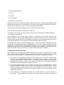
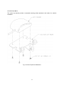
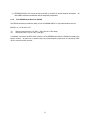
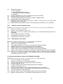
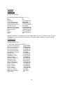
3.1 MECHANICAL DIMENSIONS
The GPS 35LP is a complete GPS receiver including antenna in a uniquely styled waterproof package.
3.1.1 GPS 35 Dimensions
(General tolerance ± 0.50mm)
Fig. 2 GPS 35LP Dimensions
8
3.2 MOUNTING CONFIGURATIONS AND OPTIONS
The following mounting options are available for the GPS 35LP. Mounting is user configurable.
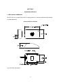
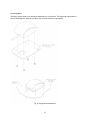
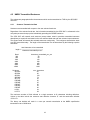
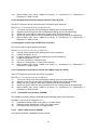
3.2.1 Magnetic Mount
The magnetic mount provides a firm, removable mounting attachment to any ferrous metal surface.
Fig. 3, Magnetic Mount Attachment
9
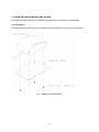
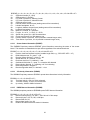
3.2.2 Trunk Lip Mount
The trunk lip mount provides a semi-permanent attachment to the trunk lip of most automobiles.
Fig. 4, Trunk Lip Mount Attachment
10
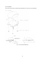
3.2.3 Suction Cup Mount
The suction cup bracket provides a removable mounting surface attached to the inside of a vehicle's
windshield.
Fig. 5, Suction Cup Mount Attachment
11
3.2.4 Flange Mount
The flange mount allows for a permanent installation on a flat surface. This mounting configuration is
ideal in applications in which the far side of the mounting surface is inaccessible.
Fig. 6, Flange Mount Attachment
12
3.3 CONNECTION WIRING DESCRIPTION
The GPS 35LP features a stripped and pre-tinned cable assembly for connection flexibility. The following
is a functional description of each wire in the cable assembly.
Red:
Vin - Regulated +3.6V to +6V, 150 mA (maximum) in the -LVx versions. Typical operating
current is 120 mA. Transients and overvoltages are protected by an internal 6.8V transient
zener diode and a positive temperature coefficient thermistor. With voltages greater than
6.8Vdc the zener will draw several amps of current through the thermistor, causing it to heat
rapidly and eventually power the unit off, unless an external fuse blows first. When proper
supply voltages are returned, the thermistor will cool and allow the GPS 35-LVx to operate.
The CMOS/TTL output buffers are powered by Vin, therefore a 3.6Vdc supply will create
3.6V logic output levels.
In the -HVx versions, Vin can be an unregulated 6.0Vdc to 40Vdc, optimized for 12Vdc.
Typical operating power is 800mW This voltage drives a switching regulator with a nominal
4.4Vdc output, which powers the internal linear regulators, and the CMOS output buffers.
Black: GND - Power and Signal Ground
White: TXD1 - First Serial Asynchronous Output. CMOS/TTL output levels vary between 0V and
Vin in the -LVC version. In the -LVS and -HVS versions a RS-232 compatible output driver
is available. This output normally provides serial data which is formatted per “NMEA 0183,
Version 2.0”. Switchable to 300, 600, 1200, 2400, 4800, 9600 or 19200 BAUD. The default
BAUD is 4800.
Blue: RXD1 - First Serial Asynchronous Input. RS-232 compatible with maximum input voltage
range -25 < V < 25.
This input may also be directly connected to standard 3 to 5Vdc
CMOS logic. The minimum low signal voltage requirement is 0.8V, and the maximum high
signal voltage requirement is 2.4V. Maximum load impedance is 4.7K ohms. This input
may be used to receive serial initialization / configuration data, as specified in Section 4.1.
Purple: TXD2 - Second Serial Asynchronous Output. Electrically identical to TXD1. This output
provides phase data information for software version 2.03 or above. See Appendix C for
details.
Green: RXD2 - Second Serial Asynchronous Input. Electrically identical to RXD1. This input may
be used to receive serial differential GPS data formatted per “RTCM Recommended
Standards For Differential Navstar GPS Service, Version 2.1” (see Section 4 for more
details).
Gray: PPS - One-Pulse-Per-Second Output. Typical voltage rise and fall times are 300 nSec.
Impedance is 250 ohms. Open circuit output voltage is 0V and Vin in the -LVx versions,
and 0V and 4.4V in the -HVx. The default format is a 100 millisecond high pulse at a 1Hz
rate, the pulse width is programmable from a configuration command in 20msec
increments. Rising edge is synchronized to the start of each GPS second. This output will
provide a nominal 700 mVp-p signal into a 50 Ohm load. The pulse time measured at the
50% voltage point will be about 50 nSec earlier with a 50 Ohm load than with no load.
Yellow: POWER DOWN - External Power Down Input. Inactive if not connected or less than 0.5V.
Active if greater than 2.7V. Typical switch point is 2.0V @ 0.34 mA. Input impedance is
15K Ohms.
Activation of this input powers the internal regulators off and drops the
supply current below 20mA in the -LVx versions, and below 1mA in the -HVx. The
computer will be reset when power is restored.
Section 4
13
Software Interface
The GPS 35LP interface protocol design is based on the National Marine Electronics Association’s
NMEA 0183 ASCII interface specification, which is fully defined in “NMEA 0183, Version 2.0” (copies
may be obtained from NMEA, P.O. Box 50040, Mobile, AL, 36605, USA) and the Radio Technical
Commission for Maritime Services’ “RTCM Recommended Standards For Differential Navstar GPS
Service, Version 2.1, RTCM Special Committee No. 104” (copies may be obtained from RTCM, P.O. Box
19087, Washington, DC, 20036, USA). The GPS 35LP interface protocol, in addition to transmitting
navigation information as defined by NMEA 0183, transmits additional information using the convention
of GARMIN proprietary sentences.
The following sections describe the data format of each sentence transmitted and received by the GPS
35LP sensor. The baud rate selection, one-pulse-per-second output interfaces and RTCM differential
GPS input are also described.
4.1
NMEA Received sentences
The subsequent paragraphs define the sentences which can be received on RXD1 by the GPS 35LP
receivers. Null fields in the configuration sentence indicate no change in the particular configuration
parameter.
All sentences received by the GPS 35LP must be terminated with <CR><LF>, but do not require the
checksum *hh. The checksum is used for parity checking data and it is recommended that the checksum
be used in environments containing high electromagnetic noise. It is generally not required in normal PC
environments. Sentences may be truncated by <CR><LF> after any data field and valid fields up to that
point will be acted on by the GPS 35LP.
4.1.1
Almanac Information (ALM)
$GPALM,<1>,<2>,<3>,<4>,<5>,<6>,<7>,<8>,<9>,<10>,<11>,<12>,<13>,<14>,<15> *hh<CR><LF>
The $GPALM sentence can be used to initialize the receivers stored almanac information if battery backup has failed.
<1>
<2>
<3>
<4>
<5>
<6>
<7>
<8>
<9>
<10>
<11>
<12>
<13>
<14>
<15>
Total number of ALM sentences to be transmitted by the sensor board during almanac download.
This field can be null or any number when sending almanac to the sensor board.
Number of current ALM sentence. This field can be null or any number when sending almanac
to the sensor board.
Satellite PRN number, 01 to 32.
GPS week number.
SV health, bits 17-24 of each almanac page.
Eccentricity
Almanac reference time.
Inclination angle.
Rate of right ascension.
Root of semi major axis.
Omega, argument of perigee.
Longitude of ascension node.
Mean anomaly
afo clock parameter
af1 clock parameter
14
4.1.2
Sensor Initialization Information (PGRMI)
The $PGRMI sentence provides information used to initialize the sensor board set position and time
used for satellite acquisition. Receipt of this sentence by the board set causes the software to restart the
satellite acquisition process. If there are no errors in the sentence, it will be echoed upon receipt. If an
error is detected, the echoed PGRMI sentence will contain the current default values. Current PGRMI
defaults can also be obtained by sending $PGRMIE to the board.
$PGRMI,<1>,<2>,<3>,<4>,<5>,<6>,<7>*hh<CR><LF>
<1>
<2>
<3>
<4>
<5>
<6>
<7>
4.1.3
Latitude, ddmm.mmm format (leading zeros must be transmitted)
Latitude hemisphere, N or S
Longitude, dddmm.mmm format (leading zeros must be transmitted)
Longitude hemisphere, E or W
Current UTC date, ddmmyy format
Current UTC time, hhmmss format
Receiver Command, A = Auto Locate, R = Unit Reset.
Sensor Configuration Information (PGRMC)
The $PGRMC sentence provides information used to configure the sensor board operation.
Configuration parameters are stored in non-volatile memory and retained between power cycles. The
GPS 35LP will echo this sentence upon its receipt if no errors are detected. If an error is detected, the
echoed PGRMC sentence will contain the current default values. Current default values can also be
obtained by sending $PGRMCE to the board.
$PGRMC,<1>,<2>,<3>,<4>,<5>,<6>,<7>,<8>,<9>,<10>,<11>,<12>,<13>,<14>*hh<CR><LF>
<1>
<2>
<3>
<4>
<5>
<6>
<7>
<8>
<9>
<10>
<11>
<12>
<13>
<14>
Fix mode, A = automatic, 2 = 2D exclusively (host system must supply altitude), 3 = 3D
exclusively
Altitude above/below mean sea level, -1500.0 to 18000.0 meters
Earth datum index. If the user datum index (96) is specified, fields <4> through <8> must
contain valid values. Otherwise, fields <4> through <8> must be null. Refer to Appendix A for a
list of earth datums and the corresponding earth datum index.
User earth datum semi-major axis, 6360000.0 to 6380000.0 meters (.001 meters resolution)
User earth datum inverse flattening factor, 285.0 to 310.0 (10-9 resolution)
User earth datum delta x earth centered coordinate, -5000.0 to 5000.0 meters (1 meter
resolution)
User earth datum delta y earth centered coordinate, -5000.0 to 5000.0 meters (1 meter
resolution)
User earth datum delta z earth centered coordinate, -5000.0 to 5000.0 meters (1 meter
resolution)
Differential mode, A = automatic (output DGPS data when available, non-DGPS otherwise), D =
differential exclusively (output only differential fixes)
NMEA Baud rate, 1 = 1200, 2 = 2400, 3 = 4800, 4 = 9600, 5 = 19200, 6 = 300, 7 = 600
Velocity filter, 0 = No filter, 1 = Automatic filter, 2-255 = Filter time constant (10 = 10 second
filter
PPS mode, 1 = No PPS, 2 = 1 Hz
PPS pulse length, 0-48 = (n+1)*20msec. Example n = 4 ð 100 msec pulse
Dead reckoning valid time 1-30 (sec)
15
All configuration changes take effect after receipt of a valid value except baud rate and PPS mode.
Baud rate and PPS mode changes take effect on the next power cycle or an external reset event.
4.1.4
Additional Sensor Configuration Information (PGRMC1)
The $PGRMC1 sentence provides additional information used to configure the sensor board operation.
Configuration parameters are stored in non-volatile memory and retained between power cycles. The
GPS 35LP will echo this sentence upon its receipt if no errors are detected. If an error is detected, the
echoed PGRMC1 sentence will contain the current default values. Current default values can also be
obtained by sending $PGRMC1E to the board.
$PGRMC1,<1>,<2>,<3>,<4>,<5>,<6>,<7>*hh<CR><LF>
<1>
<2>
<3>
<4>
<5>
<6>
<7>
NMEA output time 1-900 (sec).
Binary Phase Output Data, 1 = Off, 2 = On.
Position pinning, 1 = Off, 2 = On.
DGPS beacon frequency – 0.0, 283.5 – 325.0 kHz in 0.5 kHz steps.
DGPS beacon bit rate – 0, 25, 50, 100, or 200 bps.
DGPS beacon auto tune on station loss, 1 = Off, 2 = On.
Activate NMEA 2.30 mode indicator, 1 = Off, 2 = On.
Configuration changes take effect on the next power cycle or an external reset event. At power up or
external reset, a stored beacon frequency other than 0.0 causes the GPS 35LP to tune the beacon
receiver.
4.1.5
Output Sentence Enable/Disable (PGRMO)
The $PGRMO sentence provides the ability to enable and disable specific output sentences.
The following sentences are enabled at the factory: GPGGA, GPGSA, GPGSV, GPRMC, and PGRMT.
$PGRMO,<1>,<2>*hh<CR><LF>
<1>
<2>
Target sentence description (e.g., PGRMT, GPGSV, etc.)
Target sentence mode, where:
0 = disable specified sentence
1 = enable specified sentence
2 = disable all output sentences
3 = enable all output sentences (except GPALM)
The following notes apply to the PGRMO input sentence:
1) If the target sentence mode is ‘2’ (disable all) or ‘3’ (enable all), the target sentence description is
not checked for validity. In this case, an empty field is allowed (e.g., $PGRMO,,3), or the mode
field may contain from 1 to 5 characters.
2) If the target sentence mode is ‘0’ (disable) or ‘1’ (enable), the target sentence description field must
be an identifier for one of the sentences being output by the GPS 25LP.
3) If either the target sentence mode field or the target sentence description field is not valid, the
PGRMO sentence will have no effect.
16
4) $PGRMO,GPALM,1 will cause the sensor board to transmit all stored almanac information. All
other NMEA sentence transmission will be temporarily suspended.
4.1.6
Tune DGPS Beacon Receiver (PSLIB)
The $PSLIB sentence provides the ability to tune a GARMIN GBR-21 or equivalent beacon receiver.
$PSLIB,<1>,<2>*hh<CR><LF>
<1>
<2>
Beacon tune frequency, 0.0, 283.5 – 325.0 kHz in 0.5 kHz steps
Beacon bit rate, 0, 25, 50, 100, or 200 bps
If valid data is received, the GPS 35LP will store it in the EEPROM and echo the PSLIB command to the
beacon receiver. At power up or external reset, any stored frequency other than 0.0 causes the GPS
35LP to tune the beacon receiver.
17
4.2
NMEA Transmitted Sentences
The subsequent paragraphs define the sentences which can be transmitted on TXD1 by the GPS 35LP
receivers.
4.2.1
Sentence Transmission Rate
Sentences are transmitted with respect to the user selected baud rate.
Regardless of the selected baud rate, the information transmitted by the GPS 35LP is referenced to the
one-pulse-per-second output pulse immediately preceding the GPRMC sentence.
The GPS 35LP will transmit each sentence (except where noted in particular transmitted sentence
descriptions) at a periodic rate based on the user selected baud rate and user selected output sentences.
The sensor board will transmit the selected sentences contiguously. The contiguous transmission starts
at a GPS second boundary. The length of the transmission can be determined by the following equation
and tables:
total characters to be transmitted
length = -------------------------------------------characters transmitted per sec
Baud
300
600
1200
2400
4800
9600
19200
Sentence
GPGGA
GPGSA
GPGSV
GPRMC
GPVTG
PGRMB
PGRME
PGRMT
PGRMV
PGRMF
LCGLL
LCVTG
characters_transmitted_per_sec
30
60
120
240
480
960
1920
max_characters
81
66
210
74
42
26
35
50
32
82
44
39
The maximum number of fields allowed in a single sentence is 82 characters including delimiters.
Values in the table include the sentence start delimiter character “$” and the termination delimiter
<CR><LF>.
The factory set defaults will result in a once per second transmission at the NMEA specification
transmission rate of 4800 baud.
18
4.2.2 Transmitted Time
The GPS 35LP receivers output UTC (Coordinated Universal Time) date and time of day in the
transmitted sentences. Prior to the initial position fix, the date and time of day are provided by the onboard clock. After the initial position fix, the date and time of day are calculated using GPS satellite
information and are synchronized with the one-pulse-per-second output.
The GPS 35LP uses information obtained from the GPS satellites to add or delete UTC leap seconds
and correct the transmitted date and time of day. The transmitted date and time of day for leap second
correction follow the guidelines in “National Institute of Standards and Technology Special Publication
432 (Revised 1990)” (for sale by the Superintendent of Documents, U.S. Government Printing Office,
Washington, DC, 20402, USA).
When a positive leap second is required, the second is inserted beginning at 23h 59m 60s of the last day
of a month and ending at 0h 0m 0s of the first day of the following month. The minute containing the
leap second is 61 seconds long. The GPS 35LP would have transmitted this information for the leap
second added December 31, 1989 as follows:
Date
311289
311289
010190
Time
235959
235960
000000
If a negative leap second should be required, one second will be deleted at the end of some UTC month.
The minute containing the leap second will be only 59 seconds long. In this case, the GPS 35LP will not
transmit the time of day 23h 59m 59s for the day from which the leap second is removed.
4.2.3
Global Positioning System Almanac Data (ALM)
<field information> can be found in section 4.1.1.
$GPALM,<1>,<2>,<3>,<4>,<5>,<6>,<7>,<8>,<9>,<10>,<11>,<12>,<13>,<14>,<15>*hh<CR><LF>
Almanac sentences are not normally transmitted. Almanac transmission can be initiated by sending the
sensor board a $PGRMO,GPALM,1 command. Upon receipt of this command the sensor board will
transmit available almanac information on GPALM sentences. During the transmission of almanac
sentences other NMEA data output will be temporarily suspended.
<field information> can be found in section 4.1.1.
4.2.4
Global Positioning System Fix Data (GGA)
$GPGGA,<1>,<2>,<3>,<4>,<5>,<6>,<7>,<8>,<9>,M,<10>,M,<11>,<12>*hh<CR><LF>
<1>
<2>
<3>
<4>
<5>
UTC time of position fix, hhmmss format
Latitude, ddmm.mmmm format (leading zeros will be transmitted)
Latitude hemisphere, N or S
Longitude, dddmm.mmmm format (leading zeros will be transmitted)
Longitude hemisphere, E or W
19
<6>
<7>
<8>
<9>
<10>
<11>
<12>
4.2.5
GPS quality indication,
0 = fix not available,
1 = Non-differential GPS fix available,
2 = Differential GPS (DGPS) fix available
6 = Estimated
Number of satellites in use, 00 to 12 (leading zeros will be transmitted)
Horizontal dilution of precision, 0.5 to 99.9
Antenna height above/below mean sea level, -9999.9 to 99999.9 meters
Geoidal height, -999.9 to 9999.9 meters
Differential GPS (RTCM SC-104) data age, number of seconds since last valid RTCM
transmission (null if non-DGPS)
Differential Reference Station ID, 0000 to 1023 (leading zeros transmitted, null if non-DGPS)
GPS DOP and Active Satellites (GSA)
$GPGSA,<1>,<2>,<3>,<3>,<3>,<3>,<3>,<3>,<3>,<3>,<3>,<3>,<3>,<3>,<4>,<5>,<6>*hh<CR><LF>
<1>
Mode, M = manual, A = automatic
<2>
Fix type, 1 = not available, 2 = 2D, 3 = 3D
<3>
PRN number, 01 to 32, of satellite used in solution, up to 12 transmitted (leading zeros will be
transmitted)
<4>
Position dilution of precision, 0.5 to 99.9
<5>
Horizontal dilution of precision, 0.5 to 99.9
<6>
Vertical dilution of precision, 0.5 to 99.9
4.2.6
GPS Satellites in View (GSV)
$GPGSV,<1>,<2>,<3>,<4>,<5>,<6>,<7>,...<4>,<5>,<6>,<7>*hh<CR><LF>
<1>
Total number of GSV sentences to be transmitted
<2>
Number of current GSV sentence
<3>
Total number of satellites in view, 00 to 12 (leading zeros will be transmitted)
<4>
Satellite PRN number, 01 to 32 (leading zeros will be transmitted)
<5>
Satellite elevation, 00 to 90 degrees (leading zeros will be transmitted)
<6>
Satellite azimuth, 000 to 359 degrees, true (leading zeros will be transmitted)
<7>
Signal to noise ratio (C/No) 00 to 99 dB, null when not tracking (leading zeros will be transmitted)
NOTE: Items <4>,<5>,<6> and <7> repeat for each satellite in view to a maximum of four (4) satellites
per sentence. Additional satellites in view information must be sent in subsequent sentences.
These fields will be null if unused.
4.2.7 Recommended Minimum Specific GPS/TRANSIT Data (RMC)
$GPRMC,<1>,<2>,<3>,<4>,<5>,<6>,<7>,<8>,<9>,<10>,<11>,<12>*hh<CR><LF>
<1>
UTC time of position fix, hhmmss format
<2>
Status, A = Valid position, V = NAV receiver warning
<3>
Latitude, ddmm.mmmm format (leading zeros will be transmitted)
<4>
Latitude hemisphere, N or S
<5>
Longitude, dddmm.mmmm format (leading zeros will be transmitted)
<6>
Longitude hemisphere, E or W
<7>
Speed over ground, 0000.0 to 1851.8 knots (leading zeros will be transmitted)
<8>
Course over ground, 000.0 to 359.9 degrees, true (leading zeros will be transmitted)
<9>
UTC date of position fix, ddmmyy format
<10> Magnetic variation, 000.0 to 180.0 degrees (leading zeros will be transmitted)
<11> Magnetic variation direction, E or W (westerly variation adds to true course)
20
<12>
Mode indicator (only output if NMEA 2.30 active), A = Autonomous, D = Differential, E =
Estimated, N = Data not valid
4.2.8 Track Made Good and Ground Speed with GPS Talker ID (VTG)
The GPVTG sentence reports track and velocity information with a checksum:
$GPVTG,<1>,T,<2>,M,<3>,N,<4>,K,<5>*hh<CR><LF>
<1>
True course over ground, 000 to 359 degrees (leading zeros will be transmitted)
<2>
Magnetic course over ground, 000 to 359 degrees (leading zeros will be transmitted)
<3>
Speed over ground, 000.0 to 999.9 knots (leading zeros will be transmitted)
<4>
Speed over ground, 0000.0 to 1851.8 kilometers per hour (leading zeros will be transmitted)
<5>
Mode indicator (only output if NMEA 2.30 active), A = Autonomous, D = Differential, E =
Estimated, N = Data not valid
4.2.9 Geographic Position with LORAN Talker ID (LCGLL)
The LCGLL sentence reports position information.
$LCGLL,<1>,<2>,<3>,<4>,<5>,<6>,<7><CR><LF>
<1>
Latitude, ddmm.mmmm format (leading zeros will be transmitted)
<2>
Latitude hemisphere, N or S
<3>
Longitude, dddmm.mmmm format (leading zeros will be transmitted)
<4>
Longitude hemisphere, E or W
<5>
UTC time of position fix, hhmmss format
<6>
Status, A = Valid position, V = NAV receiver warning
<7>
Mode indicator (only output if NMEA 2.30 active), A = Autonomous, D = Differential, E =
Estimated, N = Data not valid
4.2.10 Track Made Good and Ground Speed with LORAN Talker ID (LCVTG)
The LCVTG sentence reports track and velocity information.
$LCVTG,<1>,T,<2>,M,<3>,N,<4>,K,<5><CR><LF>
<1>
True course over ground, 000 to 359 degrees (leading zeros will be transmitted)
<2>
Magnetic course over ground, 000 to 359 degrees (leading zeros will be transmitted)
<3>
Speed over ground, 000.0 to 999.9 knots (leading zeros will be transmitted)
<4>
Speed over ground, 0000.0 to 1851.8 kilometers per hour (leading zeros will be transmitted)
<5>
Mode indicator (only output if NMEA 2.30 active), A = Autonomous, D = Differential, E =
Estimated, N = Data not valid
4.2.11
Estimated Error Information (PGRME)
The GARMIN Proprietary sentence $PGRME reports estimated position error information.
$PGRME,<1>,M,<2>,M,<3>,M*hh<CR><LF>
<1>
Estimated horizontal position error (HPE), 0.0 to 999.9 meters
<2>
Estimated vertical position error (VPE), 0.0 to 999.9 meters
<3>
Estimated position error (EPE), 0.0 to 999.9 meters
4.2.12
GPS Fix Data Sentence (PGRMF)
The sentence $PGRMF is GARMIN Proprietary format.
21
$PGRMF,<1>,<2>,<3>,<4>,<5>,<6>,<7>,<8>,<9>,<10>,<11>,<12>,<13>,<14>,<15>*hh<CR><LF>
<1>
GPS week number (0 - 1023)
<2>
GPS seconds (0 - 604799)
<3>
UTC date of position fix, ddmmyy format
<4>
UTC time of position fix, hhmmss format
<5>
GPS leap second count
<6>
Latitude, ddmm.mmmm format (leading zeros will be transmitted)
<7>
Latitude hemisphere, N or S
<8>
Longitude, dddmm.mmmm format (leading zeros will be transmitted)
<9>
Longitude hemisphere, E or W
<10> Mode, M = manual, A = automatic
<11> Fix type, 0 = no fix, 1 = 2D fix, 2 = 3D fix
<12> Speed over ground, 0 to 1851 kilometers/hour
<13> Course over ground, 0 to 359 degrees, true
<14> Position dilution of precision, 0 to 9 (rounded to nearest integer value)
<15> Time dilution of precision, 0 to 9 (rounded to nearest integer value)
4.2.13
Sensor Status Information (PGRMT)
The GARMIN Proprietary sentence $PGRMT gives information concerning the status of the sensor
board. This sentence is transmitted once per minute regardless of the selected baud rate.
$PGRMT,<1>,<2>,<3>,<4>,<5>,<6>,<7>,<8>,<9>*hh<CR><LF>
<1>
Product, model and software version (variable length field, e.g., “GPS 25LP VER 1.10”)
<2>
ROM checksum test, P = pass, F = fail
<3>
Receiver failure discrete, P = pass, F = fail
<4>
Stored data lost, R = retained, L = lost
<5>
Real time clock lost, R = retained, L = lost
<6>
Oscillator drift discrete, P = pass, F = excessive drift detected
<7>
Data collection discrete, C = collecting, null if not collecting
<8>
Board temperature in degrees C
<9>
Board configuration data, R = retained, L = lost
4.2.14
3D velocity Information (PGRMV)
The GARMIN Proprietary sentence $PGRMV reports three-dimensional velocity information.
$PGRMV,<1>,<2>,<3>*hh<CR><LF>
<1>
True east velocity, -514.4 to 514.4 m/second
<2>
True north velocity, -514.4 to 514.4 m/second
<3>
Up velocity, -999.9 to 9999.9 m/second
4.2.15
DGPS Beacon Information (PGRMB)
The GARMIN proprietary sentence $PGRMB reports DGPS beacon information.
$PGRMB,<1>,<2>,<3>,<4>,<5>,K*<CR><LF>
<1>
Beacon tune frequency, 0.0, 283.5 – 325.0 kHz in 0.5 kHz steps
<2>
Beacon bit rate, 0, 25, 50, 100, or 200 bps
<3>
Beacon SNR, 0 to 31
<4>
Beacon data quality, 0 to 100
<5>
Distance to beacon reference station in kilometers
22
4.3
Baud Rate Selection
Baud rate selection can be performed by sending the appropriate configuration sentence to the sensor
board as described in the NMEA input sentences selection. (Section 4.1)
4.4
One-Pulse-Per-Second Output
The highly accurate one-pulse-per-second output is provided for applications requiring precise timing
measurements. The signal is generated after the initial position fix has been calculated and continues
until power down. The rising edge of the signal is synchronized to the start of each GPS second.
Regardless of the selected baud rate, the information transmitted by the GPS 35LP receiver is
referenced to the pulse immediately preceding the NMEA 0183 RMC sentence.
The accuracy of the one-pulse-per-second output is maintained only while the GPS 35LP can compute a
valid position fix. To obtain the most accurate results, the one-pulse-per-second output should be
calibrated against a local time reference to compensate for cable and internal receiver delays and the
local time bias.
The default pulse width is 100 msec, however; it may be programmed is 20 msec increments between 20
msec and 980 msec as described in $PGRMC Section 4.1.3 character <13>.
4.5
RTCM Received Data
Position accuracy of less than 5 meters can be achieved with the GPS 35LP by using Differential GPS
(DGPS) real-time pseudo-range correction data in RTCM SC-104 format, with message types 1, 2, 3,
and 9. These corrections can be received by the GPS 35LP receiver on RXD2. Correction data at
speeds of 300, 600, 1200, 2400, 4800 or 9600 baud can be utilized, as the GPS 35LP automatically
detects the incoming baud rate. For details on the SC-104 format, refer to RTCM Paper 134-89/SC 10468 by the Radio Technical Commission for Maritime Services.
23
Appendix A
Earth Datums
The following is a list of the GARMIN GPS 35LP earth datum indexes and the corresponding earth
datum name (including the area of application):
0
1
2
3
4
5
6
7
8
9
10
11
12
13
14
15
16
17
18
19
20
21
22
23
24
25
26
27
28
29
30
31
32
33
34
35
36
37
38
39
40
41
ADINDAN - Ethiopia, Mali, Senegal, Sudan
AFGOOYE - Somalia
AIN EL ABD 1970 - Bahrain Island, Saudi Arabia
ANNA 1 ASTRO 1965 - Cocos Island
ARC 1950 - Botswana, Lesotho, Malawi, Swaziland, Zaire, Zambia, Zimbabwe
ARC 1960 - Kenya, Tanzania
ASCENSION ISLAND 1958 - Ascension Island
ASTRO BEACON “E” - Iwo Jima Island
AUSTRALIAN GEODETIC 1966 - Australia, Tasmania Island
AUSTRALIAN GEODETIC 1984 - Australia, Tasmania Island
ASTRO DOS 71/4 - St. Helena Island
ASTRONOMIC STATION 1952 - Marcus Island
ASTRO B4 SOROL ATOLL - Tern Island
BELLEVUE (IGN) - Efate and Erromango Islands
BERMUDA 1957 - Bermuda Islands
BOGOTA OBSERVATORY - Colombia
CAMPO INCHAUSPE - Argentina
CANTON ASTRO 1966 - Phoenix Islands
CAPE CANAVERAL - Florida, Bahama Islands
CAPE - South Africa
CARTHAGE - Tunisia
CHATHAM 1971 - Chatham Island (New Zealand)
CHUA ASTRO - Paraguay
CORREGO ALEGRE - Brazil
DJAKARTA (BATAVIA) - Sumatra Island (Indonesia)
DOS 1968 - Gizo Island (New Georgia Islands)
EASTER ISLAND 1967 - Easter Island
EUROPEAN 1950 - Austria, Belgium, Denmark, Finland, France, Germany, Gibraltar,
Greece, Italy, Luxembourg, Netherlands, Norway, Portugal, Spain, Sweden, Switzerland
EUROPEAN 1979 - Austria, Finland, Netherlands, Norway, Spain, Sweden, Switzerland
FINLAND HAYFORD 1910 - Finland
GANDAJIKA BASE - Republic of Maldives
GEODETIC DATUM 1949 - New Zealand
ORDNANCE SURVEY OF GREAT BRITAIN 1936 - England, Isle of Man, Scotland,
Shetland Islands, Wales
GUAM 1963 - Guam Island
GUX 1 ASTRO - Guadalcanal Island
HJORSEY 1955 - Iceland
HONG KONG 1963 - Hong Kong
INDIAN - Bangladesh, India, Nepal
INDIAN - Thailand, Vietnam
IRELAND 1965 - Ireland
ISTS O73 ASTRO 1969 - Diego Garcia
JOHNSTON ISLAND 1961 - Johnston Island
24
42
43
44
45
46
47
48
49
50
51
52
53
54
55
56
57
KANDAWALA - Sri Lanka
KERGUELEN ISLAND - Kerguelen Island
KERTAU 1948 - West Malaysia, Singapore
L.C. 5 ASTRO - Cayman Brac Island
LIBERIA 1964 - Liberia
LUZON - Mindanao Island
LUZON - Phillippines (excluding Mindanao Island)
MAHE 1971 - Mahe Island
MARCO ASTRO - Salvage Islands
MASSAWA - Eritrea (Ethiopia)
MERCHICH - Morocco
MIDWAY ASTRO 1961 - Midway Island
MINNA - Nigeria
NORTH AMERICAN 1927 - Alaska
NORTH AMERICAN 1927 - Bahamas (excluding San Salvador Island)
NORTH AMERICAN 1927 - Central America (Belize, Costa Rica, El Salvador,
Guatemala, Honduras, Nicaragua)
58
NORTH AMERICAN 1927 - Canal Zone
59
NORTH AMERICAN 1927 - Canada (including Newfoundland Island)
60
NORTH AMERICAN 1927 - Caribbean (Barbados, Caicos Islands, Cuba, Dominican
Republic, Grand Cayman, Jamaica, Leeward Islands, Turks Islands)
61
NORTH AMERICAN 1927 - Mean Value (CONUS)
62
NORTH AMERICAN 1927 - Cuba
63
NORTH AMERICAN 1927 - Greenland (Hayes Peninsula)
64
NORTH AMERICAN 1927 - Mexico
65
NORTH AMERICAN 1927 - San Salvador Island
66
NORTH AMERICAN 1983 - Alaska, Canada, Central America, CONUS, Mexico
67
NAPARIMA, BWI - Trinidad and Tobago
68
NAHRWAN - Masirah Island (Oman)
69
NAHRWAN - Saudi Arabia
70
NAHRWAN - United Arab Emirates
71
OBSERVATORIO 1966 - Corvo and Flores Islands (Azores)
72
OLD EGYPTIAN - Egypt
73
OLD HAWAIIAN - Mean Value
74
OMAN - Oman
75
PICO DE LAS NIEVES - Canary Islands
76
PITCAIRN ASTRO 1967 - Pitcairn Island
77
PUERTO RICO - Puerto Rico, Virgin Islands
78
QATAR NATIONAL - Qatar
79
QORNOQ - South Greenland
80
REUNION - Mascarene Island
81
ROME 1940 - Sardinia Island
82
RT 90 - Sweden
83
PROVISIONAL SOUTH AMERICAN 1956 - Bolivia, Chile, Colombia, Ecuador, Guyana,
Peru, Venezuela
84
SOUTH AMERICAN 1969 - Argentina, Bolivia, Brazil, Chile, Colombia, Ecuador,
Guyana,
Paraguay, Peru, Venezuela, Trinidad and Tobago
85
SOUTH ASIA - Singapore
86
PROVISIONAL SOUTH CHILEAN 1963 - South Chile
87
SANTO (DOS) - Espirito Santo Island
88
SAO BRAZ - Sao Miguel, Santa Maria Islands (Azores)
89
SAPPER HILL 1943 - East Falkland Island
90
SCHWARZECK - Namibia
25
91
92
93
94
95
96
97
98
99
100
101
102
103
104
105
106
107
SOUTHEAST BASE - Porto Santo and Madeira Islands
SOUTHWEST BASE - Faial, Graciosa, Pico, Sao Jorge, and Terceira Islands (Azores)
TIMBALAI 1948 - Brunei and East Malaysia (Sarawak and Sabah)
TOKYO - Japan, Korea, Okinawa
TRISTAN ASTRO 1968 - Tristan da Cunha
User defined earth datum
VITI LEVU 1916 - Viti Levu Island (Fiji Islands)
WAKE-ENIWETOK 1960 - Marshall Islands
WORLD GEODETIC SYSTEM 1972
WORLD GEODETIC SYSTEM 1984
ZANDERIJ - Surinam
CH-1903 - Switzerland
Hu - Tzu - Shan
Indonesia 74
Austria
Potsdam
Taiwan (modified Hu-Tzu-Shan)
26
Appendix B
GPS 35LP Evaluation Kits
GPS 35LP evaluation materials kit (part number 010-10186-00) is available from Garmin International.
This kit includes two DB-9 connectors with solder pots, various mounting brackets, hookup wire, technical
specification, and software to monitor the GPS 35LP outputs and configure the receiver.
To install the evaluation and configuration software run the program, setup, by using the FILE - RUN
command in Windows.
NMEAVWR.EXE
The NMEAVWR.EXE program in the GARMIN program group can accept NMEA data from either the
com1 or com2 PC serial port at 1200, 2400, 4800, 9600 or 19200 baud. The default settings are com1 at
4800 baud. NMEAVWR receives NMEA sentences and displays sentence information in a formatted
display on the screen.
The top portion of the screen displays the 5 character identifier of sentences received, the age in
seconds since the last transmission, and a count of the number of times the sentence has been received.
The middle portion of the screen displays the most recently received data in the sentence with the
selected NMEA identifier (highlighted in the top portion of the screen using the arrow keys).
The lower portion contains a formatted presentation of the currently selected sentence. In addition to
receiving data the program will also upload NMEA sentences to the sensor board. The ALT-U key
sequence will upload the file NMEA.TXT in the current directory to the unit. Received data can also be
logged to a file. NMEAVWR can be invoked from a DOS prompt with the following optional parameters:
<path>nmeavwr [/b:<baud>] [<port>] [log_file.txt]
where:
[]
<path>
<baud>
<port>
log_file.txt
brackets indicate optional parameters
DOS path to nmeavwr.exe if not in current directory
baud rate
PC communications port
ASCII log file of all received sentences
Example:
c:\garmin>nmeavwr /b:9600 com2 log_file.txt
If no options are used, the defaults are 4800 baud, com1, and no data logging.
GPSCFG.EXE
The configuration program GPSCFG.EXE will configure the sensor boards based on user selected
parameters. Some program features include the ability to download sensor board configuration, maintain
different configurations in files, and perform sensor board configurations quickly with the use of one
function key. Online program help is available.
27
GPS25PM.EXE
The Garmin Phase Monitor Program, GPS25PM.EXE, provides the following functions:
- Display and log phase data output from TXD2
- Upload almanac, position, and time information via RXD2
- Download almanc and ephemeris information upon command
GPS25PM.EXE can be invoked from a DOS prompt:
<path>gps25pm.exe [/com<x>] [/b:<yyyy>]
Where
<> denotes user supplied information
[] denotes optional parameters
x is com port number (1 or 2, default is 1)
yyyy is baud rate (1200, 2400, 4800, or 9600, default is 9600)
See Appendix C for detailed description and operation of the GPS25PM.EXE program.
28
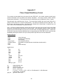
Appendix C
Phase Output Data Binary Format
Two records are transmitted once per second by the GPS 35LP. One record contains primarily postprocess information such as position and velocity information. The second record contains receiver
measurement information. The records are sent at a default baud rate of 9600 baud, 8 bits, no parity.
Records begin with a delimiter byte (10 hex). The second byte identifies the record type (28 hex for a
position record, 29 hex for a receiver measurement). The third byte indicates the size of the data. The
fourth byte is the first byte of data. The data is then followed by a chksum byte, a delimiter byte (10
hex), and an end-of-transmission character (03 hex).
Note - If RTCM-104 differential data is sent to the GPS 35LP the board will reset the Phase Output Data
baud rate to the same baud rate used for RTCM-104 data. If the differential inputs are used on the GPS
35LP then the RTCM-104 data must be sent to the GPS 35LP at 9600 baud(preferred) or 4800 baud.
RTCM-104, baud rates less than 4800 baud are not supported by the GPS 35LP since it would limit bus
bandwidth past the point where a once per second phase output data rate could be maintained.
Position Record
- 0x10
- 0x28
- 0x36
- cpo_pvt_type
- one byte chksum
- 0x10
- 0x03
typedef struct
{
float
float
float
float
int
double
double
double
float
float
float
} cpo_pvt_type;
alt
epe
eph
epv
fix
gps_tow
(dle is first byte)
(position record identifier)
(size of data)
(see description below)
(the addition of bytes between the delimiters should equal 0)
(dle)
(etx is last byte)
alt;
epe;
eph;
epv;
fix;
gps_tow;
lat;
lon;
lon_vel;
lat_vel;
alt_vel;
ellipsoid altitude (mt)
est pos error (mt)
pos err, horizontal (mt)
pos err, vertical (mt)
0 = no fix; 1 = no fix; 2 = 2D; 3 = 3D; 4 = 2D differential; 5 = 3D differential;
6 and greater - not defined
gps time of week (sec)
29
lat
lon
lon_vel
lat_vel
alt_vel
Latitude (rad)
Longitude (rad)
Longitude velocity (mt/sec)
Latitude velocity (mt/sec)
Altitude velocity (mt/sec)
Receiver Measurement Record
- 0x10
- 0x29
- 0xE2
- cpo_rcv_type
- one byte chksum
- 0x10
- 0x03
typedef struct
{
unsigned long
double
unsigned int
char
unsigned char
char
char
} cpo_rcv_sv_type;
typedef struct
{
double
int
cpo_rcv_sv_type
} cpo_rcv_type;
rcvr_tow
rcvr_wn
cycles
pr
phase
slp_dtct
snr_dbhz
svid
valid
(dle is first byte)
(receiver record identifier)
(size of data)
(see below)
(the addition of bytes between the delimiters should equal 0)
(dle)
(etx)
cycles;
pr;
phase;
slp_dtct;
snr_dbhz;
svid;
valid;
rcvr_tow;
rcvr_wn;
sv[12];
Receiver time of week (sec)
Receiver week number
Number of accumulated cycles
pseudo range (mt)
to convert to (0 -359.999) multiply by 360.0 and divide by 2048.0
0 = no cycle slip detected; non 0 = cycle slip detected
Signal strength
Satellite number (0 - 31) Note - add 1 to offset to current svid numbers
0 = information not valid; non 0 = information valid
30
dle and etx bytes:
Software written to receive the two records should filter dle and etx bytes as described below:
typedef enum
{
dat,
dle,
etx
} rx_state_type;
char
int
rx_state_type
in_que[256];
in_que_ptr = 0;
rx_state = dat;
void add_to_que( char data )
{
#define
dle_byte 0x10
#define
etx_byte 0x03
if (rx_state == dat)
{
if (data == dle_byte)
{
rx_state = dle;
}
else
{
in_que[ in_que_ptr++ ] = data;
}
}
else if (rx_state == dle)
{
if (data == etx_byte)
{
rx_state = etx;
}
else
{
rx_state = dat;
in_que[ in_que_ptr++ ] = data;
}
}
else if (rx_state == etx)
{
if (data == dle_byte)
{
rx_state = dle;
}
}
if (in_que_ptr > 255)
{
in_que_ptr = 0;
}
}
31
GARMIN Phase Monitor Program - gps25pm.exe
Command Line Arguments
default:
/com1
/b:9600
- selects which PC serial port to use for communication - com1, com2 (com1 default).
- selects the baud rate - 1200, 2400, 4800, or 9600 (9600 default)
Description:
GPS25PM.EXE is designed to interface with a Garmin GPS 25 XL or GPS 25LP sensor boards and the
GPS 35LP sensors. The program will perform the following functions:
- display and log phase data output by GPS sensors.
- upload almanac, position, and time information.
- download almanac and ephemeris information.
GPS25PM.EXE is a DOS based program and will run on IBM 80286 or greater compatible PCs.
Displayed Information:
The GPS25PM.EXE display page is divided into 3 sections. The top-most section contains the following
information updated at once a second:
A. Position
1. WGS 84 Latitude, Longitude (degrees - minutes) - 0.0001 minute resolution.
2. Ellipsoid Altitude (meters) - 1 meter resolution.
B. Velocity
1. Each of 3 axis (meters per second) - 0.01 m/s resolution.
2. Altitude (meters/minute) - 1 mt/m resolution.
3. Ground Speed (kilometers/hour) - 0.1 km/h resolution
C. Estimated Position Error - Vertical, Horizontal, Total (meters) - 1 meter resolution
D. Track - (0 - 359 degrees) - 0.1 degree resolution
E. Time
1. GPS time (hours - minutes - seconds) - 1 sec. resolution (not leap second corrected)
2. Receiver Time of Week (GPS seconds) - 0.00000001 sec. resolution.
The middle section contains receiver measurement information for satellites which the GPS sensor is
currently tracking. This information is updated once at second:
A Satellite Number (1 - 32)
B. Signal to Noise Ratio (dbHz) - 1 dbHz resolution.
C. Phase (0 - 359 degrees) - 0.1 degree resolution.
D. Pseudo Range (meters) - 1 meter resolution.
E. Accumulated Cycles (cycles) - 1 cycle resolution.
32
The bottom section contains program messages. Upload and download status messages will appear
here as well as any program error messages.
Commands:
D - Download Almanac:
The GPS25 sensor will be sent a command to download almanac information. GPS25PM.EXE will
create the file ALMANAC.DAT and locate it the current working directory. If an ALMANAC.DAT exists in
the current directory it will be over-written.
U - Upload Almanac:
The ALMANAC.DAT file located in the current working directory will be read, converted to GPS25 sensor
binary format, and sent to the GPS25 sensor. This command will over-write any almanac information
already in the GPS25 sensor.
E - Download Ephemeris:
The GPS25 sensor will be sent a command to download ephemeris information. GPS25PM.EXE will
create the file EPHEMERS.DAT and locate it in the current working directory. If an EPHEMERIS.DAT
exists in the current directory it will be over-written.
P - Position and Time Upload:
The program will prompt the user for the local time offset from UTC time. This offset is then used to
determine UTC time from the PC’s real time clock. The UTC time is then uploaded to the GPS25
sensor. If an error occurs in the upload process a ‘COMM ERROR’ will be enunciated on the screen.
After the UTC time has been uploaded the user is prompted for Latitude and Longitude for position
uploading. An integer Latitude and integer Longitude should be entered on the same line separated by a
space. If the board has not yet obtained a position fix it will restart its startup sequence based on the
new position and time information.
R - Record Data
The program will prompt the user for a data file name. GPS25XL.DAT is the default. Once the file name
is obtained all information displayed in the top two sections of the screen will be formatted and written to
the data file. The format of this data file is described in the File Formats section. If the R option is
selected again, the current file will be saved and closed and a new file will be opened. Data files will be
over-written if same names are used.
33
File Formats
ALMANAC.DAT
Example almanac entry:
**** Week 794 almanac for PRN-01 ************
ID:
01
Health:
000
Eccentricity:
3.414630890E-003
Time of Applicability(s):
380928.0000
Orbital Inclination(rad):
9.549833536E-001
Rate of Right Ascen(r/s):
-7.771752131E-009
SQRT(A) (m^1/2):
5153.589843
Right Ascen at TOA(rad):
8.032501489E-002
Argument of Perigee(rad):
-1.308424592E+000
Mean Anom(rad):
2.045822620E+000
Af0(s):
9.536743164E-007
Af1(s/s):
8.367351256E-011
week:
794
Almanac information for satellites with a bad health status will not be included in this file when
downloaded from the GPS25 sensor and should not be included when uploading to the GPS25 sensor.
EPHEMERS.DAT
Example ephemeris entry:
**** Week 794. Ephemeris for PRN-18 **********
Ref Time of Clk Parms(s):
233504.000000
Ref Time of Eph Parms(s):
233504.000000
Clk Cor, Group Dly(s):
-8.280389E-006
Clk Correction af1(s/s):
-3.410605E-013
Clk Correction af2(s/s/s):
0.000000E+000
User Range Accuracy(m):
33.299999
Eccentricity(-):
5.913425E-003
SQRT(A) (m**1/2):
5.153628E+003
Mean Motion Cor(r/s):
4.710911E-009
Mean Anomaly(r):
6.033204E-001
Argument of Perigee(r):
1.418009E+000
Right Ascension(r):
3.520111E-002
Inclination Angle(r):
9.434418E-001
Rate of Right Asc(r/s):
-8.210699E-009
Rate of Inc Angle(r/s):
4.503759E-010
Lat Cor, Sine(r):
1.212582E-005
Lat Cor, Cosine(r):
2.004206E-006
Inc Cor, Sine(r):
-1.490116E-008
Inc Cor, Cosine(r):
-9.872019E-008
Radius Cor, Sine(m):
38.375000
Radius Cor, Cosine(m):
132.937500
Issue of Data :
184
34
Ephemeris Record
- 0x10
(dle is first byte)
- 0x2A
(ephemeris record identifier)
- 0x74
(size of data)
- eph_type
(see description below)
- one byte chksum (the addition of bytes between the delimiters should equal 0)
- 0x10
(dle)
- 0x03
(etx)
typedef struct
{
char svid;
int wn;
float toc;
float toe;
float af0;
float af1;
float af2;
float ura;
double e;
double sqrta;
double dn;
double m0;
double w;
double omg0;
double i0;
float odot;
float idot;
float cus;
float cuc;
float cis;
float cic;
float crs;
float crc;
byte iod;
} eph_type;
/* ephemeris record */
/* Satellite number (0 - 31)
/* week number (weeks)
/* reference time of clock parameters (s)
/* reference time of ephemeris parameters (s)
/* clock correction coefcnt - group delay (s)
/* clock correction coefficient (s/s)
/* clock correction coefficient (s/s/s)
/* user range accuracy (m)
/* eccentricity (-)
/* square root of semi-major axis (a) (m**1/2)
/* mean motion correction (r/s)
/* mean anomaly at reference time (r)
/* argument of perigee (r)
/* right ascension (r)
/* inclination angle at reference time (r)
/* rate of right ascension (r/s)
/* rate of inclination angle (r/s)
/* argument of latitude correction, sine (r)
/* argument of latitude correction, cosine (r)
/* inclination correction, sine (r)
/* inclination correction, cosine (r)
/* radius correction, sine (m)
/* radius correction, cosine (m)
/* issue of data
*/
*/
*/
*/
*/
*/
*/
*/
*/
*/
*/
*/
*/
*/
*/
*/
*/
*/
*/
*/
*/
*/
*/
*/
To initiate an ephemeris download for all tracked satellites send the following bytes in sequence:
0x10, 0x0D, 0x04, 0x02, 0x0C, 0x0, 0x0, 0xE1, 0x10, 0x03
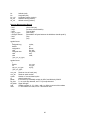
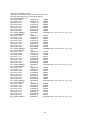
GPS25PM.DAT
Example data file entry:
35
TIM time_of_week week_number
RCV svid snr (T)rack/(C)ycle_slip phase pseudo_range cycles
PVT time lat lon alt lat_vel lon_vel alt_vel epe eph epv
TIM 235537.99855650 794
RCV 18 50 T 120.2
19964528.44
2068193
RCV 29 50 T 133.2
20364313.25
1950557
RCV 28 45 T 176.5
21135153.13
2069992
RCV 19 47 T 145.2
21190271.83
2182643
RCV 31 45 T 75.8
21240354.20
2216421
RCV 22 42 T 195.1
22849183.41
1855826
RCV 27 36 T 155.2
24234175.55
2230462
RCV 14 39 T 202.3
25147694.34
1845263
PVT 235537.99999842
38.9499588
94.7463684
TIM 235538.99853500
794
RCV 18 50 T 38.8
19958107.10
2101947
RCV 29 50 T 132.4
20358247.54
1982431
RCV 28 45 T 189.5
21128713.01
2103829
RCV 19 47 T 284.6
21183470.16
2218374
RCV 31 45 T 19.0
21233441.89
2252746
RCV 22 42 T 263.0
22843381.08
1886300
RCV 27 36 T 311.7
24227194.88
2267146
RCV 14 39 T 308.3
25141899.86
1875708
PVT 235538.99999827
38.9499550
94.7463684
TIM 235539.99851349
794
RCV 18 50 T 76.6
19951681.26
2135704
RCV 29 50 T 284.4
20352180.11
2014308
RCV 28 45 T 320.8
21122272.68
2137669
RCV 19 47 T 8.3
21176671.33
2254110
RCV 31 45 T 170.2
21226528.82
2289074
RCV 22 42 T 315.9
22837584.50
1916778
RCV 27 36 T 132.4
24220207.85
2303835
RCV 14 39 T 127.4
25136106.23
1906158
PVT 235539.99999812
38.9499512
94.7463684
TIM 235540.99849199
794
RCV 18 50 T 174.9
19945258.21
2169465
RCV 29 50 T 177.7
20346113.87
2046190
RCV 28 45 T 159.6
21115834.07
2171514
RCV 19 47 T 324.7
21169868.61
2289849
RCV 31 45 T 111.8
21219615.05
2325407
RCV 22 42 T 261.7
22831782.87
1947261
RCV 27 36 T 259.1
24213226.41
2340528
RCV 14 39 T 318.7
25130310.86
1936612
PVT 235540.99999797
38.9499474
94.7463760
TIM 235541.99847244
794
RCV 18 50 T 325.5
19938831.69
2203229
RCV 29 50 T 152.1
20340045.44
2078075
RCV 28 45 T 52.4
21109392.21
2205362
RCV 19 47 T 125.3
21163068.15
2325593
RCV 31 45 T 159.4
21212700.30
2361743
RCV 22 43 T 117.1
22825981.54
1977748
RCV 27 36 T 352.1
24206248.88
2377225
RCV 14 39 T 141.3
25124515.72
1967071
PVT 235541.99999977
38.9499474
94.7463760
36
211.7 -0.19 -0.31 0.13 28 16 23
212.6 -0.19 -0.30 0.14 28 16 23
213.5 -0.19 -0.30 0.13 28 16 23
214.4 -0.19 -0.30 0.14 28 16 23
215.4 -0.19 -0.30 0.13 28 16 23
GARMIN Corporation
1200 East 151st Street
Olathe, KS 66062
(913)397-8200
(913)397-8282 FAX
190-00148-00 Rev. E
37