1
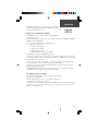
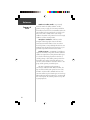
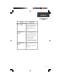
DGPS 53
integrated
GPS/DGPS receiver
owner’s
manual
and
reference
guide
DGPS53Cover.p65
1
8/29/00, 11:10 AM
© 2000 GARMIN Corporation
GARMIN International, Inc.
1200 East 151st Street, Olathe, Kansas 66062, U.S.A.
Tel. 913/397.8200 or 800/800.1020
Fax 913/397.8282
GARMIN (Europe) Ltd.
Unit 5, The Quadrangle, Abbey Park Industrial Estate, Romsey, SO51 9AQ, U.K.
Tel. 44/1794.519944
Fax 44/1794.519222
GARMIN (Asia) Corporation
No. 68, Jangshu 2nd Rd., Shijr, Taipei County, Taiwan
Tel. 886/02.2642.8999
Fax 886/02.2642.9099
All rights reserved. Except as expressly provided herein, no part of this manual may
be reproduced, copied, transmitted, disseminated, downloaded or stored in any
storage medium, for any purpose without prior written consent of GARMIN
Corporation. GARMIN Corporation hereby grants permission to download a single
copy of this manual onto a hard drive or other electronic storage medium to be
viewed for personal use, provided that such electronic or printed copy of this
manual contains the complete text of this copyright notice and provided further that
any unauthorized commercial distribution of this manual is strictly prohibited.
Information in this manual is subject to change without notice. GARMIN
Corporation reserves the right to change or improve its products and to make
changes in the content without obligation to notify any person or organization of
such changes. Visit the GARMIN website for current updates and supplemental
information concerning the use and operation of this and other GARMIN products.
Website address: www.garmin.com
GARMIN and DGPS 53 are registered trademarks of GARMIN Corporation and may
not be used without the express permission of GARMIN Corporation.
September 2000
DGPS53Cover.p65
Part Number 190-00194-00 Rev. A
2
Printed in Taiwan
8/29/00, 11:10 AM
Introduction
GARMIN Corporation warrants this product to be free
from defects in materials and workmanship for one year
from the date of purchase. GARMIN will, at its sole option,
repair or replace any components that fail in normal use.
Such repairs or replacement will be made at no charge to
the customer for parts or labor. The customer is, however,
responsible for any transportation costs. This warranty does
not cover failures due to abuse, misuse, accident or
unauthorized alteration or repairs.
THE WARRANTIES AND REMEDIES CONTAINED
HEREIN ARE EXCLUSIVE AND IN LIEU OF ALL OTHER
WARRANTIES EXPRESS OR IMPLIED OR STATUTORY,
INCLUDING ANY LIABILITY ARISING UNDER ANY
WARRANTY OF MERCHANTABILITY OR FITNESS FOR A
PARTICULAR PURPOSE, STATUTORY OR OTHERWISE.
THIS WARRANTY GIVES YOU SPECIFIC LEGAL RIGHTS,
WHICH MAY VARY FROM STATE TO STATE.
IN NO EVENT SHALL GARMIN BE LIABLE FOR ANY
INCIDENTAL, SPECIAL, INDIRECT OR CONSEQUENTIAL DAMAGES, WHETHER RESULTING FROM THE
USE, MISUSE, OR INABILITY TO USE THIS PRODUCT
OR FROM DEFECTS IN THE PRODUCT. SOME STATES
DO NOT ALLOW THE EXCLUSION OF INCIDENTAL OR
CONSEQUENTIAL DAMAGES, SO THE ABOVE
LIMITATIONS MAY NOT APPLY TO YOU.
To obtain warranty service, contact your GARMIN
dealer or call the GARMIN Customer Service department
(913-397-8200) for a returned merchandise tracking
number. The unit should be securely packaged with the
tracking number clearly marked on the outside of the
package and sent freight prepaid and insured to a GARMIN
warranty service station. A copy of the original sales receipt
is required as the proof of purchase for warranty repairs.
GARMIN retains the exclusive right to repair or replace the
unit or software or offer a full refund of the purchase price
at its sole discretion. SUCH REMEDY SHALL BE YOUR
SOLE AND EXCLUSIVE REMEDY FOR ANY BREACH OF
WARRANTY.
Limited Warranty
I
The GARMIN DGPS 53 has no
user-serviceable parts. Should
you ever encounter a problem
with your receiver, please contact
your GARMIN dealer or the
GARMIN Customer Service
department (913-397-8200 or
800-800-1020) for repairs.
Any attempt to open the case to
change or modify the unit in any
way will void your warranty and
may result in permanent damage
to the equipment.
1
Introduction
Cautions
All differential beacon receivers decode correction data
determined at the beacon transmitter site via a GPS
receiver(s). The GPS system is operated by the government of the United States which is solely responsible for
their accuracy and maintenance. The DGPS beacon
transmitters are operated by the U.S. Coast Guard (or
similar government agency in other countries) which is
responsible for their accuracy and maintenance. The
Global Positioning System and the Differential Global
Positioning System are under development and are subject
to changes which could affect accuracy and performance
of all GPS/DGPS equipment. Although a GPS/DGPS
system is a precision electronic NAVigation AID
(NAVAID), any NAVAID can be misused or misinterpreted,
and therefore become unsafe. Use the GPS/
DGPS system at your own risk. To reduce this risk,
carefully review and understand all aspects of this Owner’s
Manual and carefully compare indications from your
display to all available navigation sources including the
information from other NAVAIDs, visual sightings, charts,
etc. For safety, always resolve any discrepancies before
continuing navigation.
NOTE: This device complies with Part 15 of the FCC
rules. Operation of this device is subject to the following
conditions: (1) This device may not cause harmful
interference, and (2) this device must accept any
interference received, including interference that may
cause undesired operation.
2
Introduction
Table of
Contents
Introduction
Limited Warranty..............................................1
Cautions ..........................................................2
Table of Contents ............................................3
Product Registration ........................................4
Overview
Capabilities & Package Contents......................5
Installation
Mounting the DGPS 53................................6-7
Connecting DGPS 53....................................8-9
Operation
Using the DGPS 53 .......................................10
NMEA Sentences......................................11-18
One-Pulse-Per-Second Output.......................18
Reference
GPS: How It Works .......................................19
DGPS: How It Works ....................................20
Sources of Error .......................................21-22
Troubleshooting Chart ..................................23
DGPS 53 Specifications .................................24
Appendix A: Earth Datums.......................25-27
Index .............................................................28
3
Introduction
Customer Service Product Registration
Product
Registration
H
Why should you register your
GARMIN GPS unit?
• Notification of Product Updates
• Notification of New Products
• Lost or Stolen unit tracking
Help us better support you by completing our on-line
registration today! Have the serial number of your DGPS
53 handy and connect to our website (www.garmin.com).
Look for the Product Registration link on the Home page.
If you have previously registered a GARMIN product
purchase using a mail-in registration card, we invite you
to reregister using our NEW on-line system. Many
services provided by our new product registration system
are now being automated and reregistering your purchase
ensures you the best possible support from GARMIN.
Serial Number
Use this area to record the serial number (8-digit
number located on the bottom of the unit) in case it is
lost, stolen, or needs service. Be sure to keep your original
sales receipt in a safe place or attach a photocopy inside
the manual.
Serial Number:
*
I
*
The GARMIN DGPS 53 has no userserviceable parts. Should you ever encounter
a problem with your unit, please contact
your GARMIN dealer or GARMIN Customer
Service (913-397-8200 or 800-800-1020) for
repairs.
Repairs should only be made by an authorized
GARMIN service center. Unauthorized repairs or
modifications could void your warranty and authority to
operate this device under FCC Part 15 regulations. See
page 1 of this manual for further service details.
4
Overview
Capabilities
The DGPS 53 offers a host of powerful capabilities for
enhanced performance and accuracy:
• Performance— 12-channel GPS receiver tracks and
uses up to 12 satellites for fast, accurate positioning.
Single channel DGPS receiver has high-sensitivity
automatic and manual tuning throughout the
beacon broadcast band.
• Ease of Use— Once installed, unit will automatically transmit navigation data.
• Convenience— May be remotely mounted in an
out-of-the-way location. Receiver status information
is displayed directly on the chartplotter or PC.
• Low Power Consumption— Draws approximately
170 milliamps during normal operation.
• Accuracy— 1-5 (2DRMS) meters (typical).
Capabilities &
Package Contents
Package Contents
Your GARMIN DGPS 53 package includes:
• DGPS 53 unit
• 30’ Power/Data Cable
• Owner’s Manual & Reference Guide
• Beacon Reference Card
If any parts are missing or damaged, please
contact your GARMIN dealer immediately.
5
Installation
Mounting the Receiver
Mounting the
DGPS 53
I
Note: As a general rule,
mount the receiver at least
three feet from all other
antennas and the vessel’s
electrical system components
(alternator/ignition system).
6
Please read through these instructions thoroughly before
attempting installation. Make sure you completely understand
these instructions before you begin. When in doubt, seek
professional assistance.
The following additional items are needed or optional
to complete the installation of your DGPS 53:
• Antenna mount— Since antenna mounting
locations and methods vary, you will need to obtain
an antenna mount to install the DGPS 53. The
receiver base fits a standard 1-inch, 14 threads-perinch mount. Check with your GARMIN dealer or a
marine supply retailer for this item.
• On/Off switch (optional)— Power to the
receiver may be controlled by an on/off switch, such
as an accessory switch on the control console.
Check with your GARMIN dealer or a marine/
electric supply retailer for this item.
• GARMIN 60’ Power/Data Cable— for cable
installation lengths greater than 30’. Part number
010-10284-00
It is recommended that the system be temporarily
hooked up with the wiring and the unit placed at the
desired installation location. Then, check operation with
potential interfering equipment turned on and off. (For
example, other electronic equipment, fan motors, engine
ignition, alternators, generators, radars and VHF radio
transmissions can be sources of interference.)
Position the receiver so that the clearest possible view
of the sky and horizon in all directions is obtained. Avoid
mounting the antenna next to large areas of conductive
material (metal, aluminum, etc.) as this may cause poor
signal reception. The DGPS 53 is supplied with a 30 feet
power/data cable. When routing the wiring to the DGPS
53, avoid routing the cable near the vessel’s alternator or
ignition system components or parallel to other power
lines.
Installation
Three common sources of interference for DGPS
units are:
ABOVE- OK
Mounting the
Receiver
Radar
3'
BELOW- OK
Radar
VHF Radio Antenna
EMI
EMI (Electromagnetic Interference) from engine components
If a problem is found, try altering the location of the
unit or wiring. Often moving the antenna a few feet away
from the source of interference will solve the problem.
When a suitable configuration is found, a permanent
installation should be made. Select the mounting location
according to your preferences. Keep in mind that from this
mounting location cables will be routed to the antenna and
to the GPS unit.
I
When routing the power/data
cable, try to avoid:
• Sharp edges which may cut the
cable
• Routing the cable parallel to
other power lines
• Excessively twisting, straining or
bending the cable
1. Once a suitable mounting location has been
determined and tested, secure the antenna mount at
the desired mounting location.
2. Make sure the DGPS 53 is aligned properly to avoid
thread damage. Thread the DGPS 53 onto the
antenna mount and hand tighten clockwise until
snug (Fig. 1). Do not overtighten.
3. Align the notches on the power/data cable and
DGPS 53 connector and push the connector in until
it seats. Turn the locking ring clockwise until the
power/data cable is firmly locked into position.
4. Route the power/data cable from the DGPS 53 to the
GPS unit. Excess cable may be shortened or coiled
together and secured in an inconspicuous location. If
additional cable is needed you may use GARMIN’s
optional 60’ cable (010-10284-00) or similar 24
AWG shielded wiring. The entire length of the
power/data cable should not exceed 150’ (45.7m).
Antenna
Mount
Power/Data
Cable &
Connectors
Figure 1: Mounting
the DGPS 53
7
Installation
Connecting the
DGPS 53
F
If the DGPS 53 is being connected to
a PC, a DB9 or DB25 serial
connector (normally female) will be
needed. Check with a PC or
electronics supplier for this item.
5 4 3 2 1
9 8 7 6
DB9 Female Serial Connector
13
7
25
3 2 1
14
DB25 Female Serial Connector
I
Some non-GARMIN devices may
have a separate data line labeled
“RETURN”, “DATA GROUND” or
“DATA -”. If one of these lines exist,
connect the BLACK wire from the
power/data cable to it.
8
Connecting the DGPS 53
The final step in installing the DGPS 53 is to connect
the receiver’s DATA IN, DATA OUT, REMOTE ON/OFF
and GROUND (Return) lines to your chartplotter or PC.
The DGPS 53 is designed to transmit/receive data at
4800-19200 baud (bits per second), which is suitable for
use with most devices and PCs.
For reliable communication, it is essential that the
DGPS 53 and the receiving device share the same ground.
This ground connection acts as the (current) Return line.
It is recommended to wire the unit to it’s own circuit to
avoid interference from other electronics.
1. You may reference Figures 3 or 4 on the following
page for the wiring: Connect the BLUE (Data Out)
wire from the DGPS 53’s power/data cable to the
DATA INPUT line of the chartplotter or to pin 2 on
the DB9 (pin 3 on DB25).
2. Connect the BROWN (Data In) wire to the DATA
OUTPUT line of the chartplotter or pin 3 on the DB9
(pin 2 on DB25).
3. Connect the BLACK (-) wire to the GROUND wire of
the chartplotter or pin 5 on the DB9 (pin 7 on
DB25). If the BLACK wire is already connected to
the same ground terminal as the GPS unit, no
additional connection is required (unless a separate
RETURN line is provided by the GPS unit).
4. Connect the RED (+) wire from the power/data
cable to a 8-35 VDC power source.
5. If a remote power switch is being installed,
reference Figure 5 for wiring the switch. This will
allow the DGPS 53 to remain connected to a power
source, but manually powered on and off.
Otherwise, if the receiver is being wired to a circuit
which is already switched, (with the chartplotter for
example) connect the WHITE wire to the same place
as the BLACK wire. When the BLACK and WHITE
wires are combined, the DGPS 53 will turn on/off
when power is applied/removed to the RED (+) and
BLACK (-) wires.
6. If one-pulse-per-second (PPS) output is being used,
connect the YELLOW (+) and BLACK (-) wires to
your desired device inputs. See page 18 for more
information on PPS.
Installation
Connecting
the DGPS 53
(-)
(+)
Fuse
2-6A
8-35VDC
Chartplotter
1
7
DGPS 53
Power/Data Cable &
Chartplotter Connection
2
6
3
5
4
(1) RED: 8-35 VDC
GROUND
(2) BLACK: GROUND
(5) WHITE: REMOTE ON/OFF*
DATA OUT
(4) BROWN: DATA IN
(3) BLUE: DATA OUT
DATA IN
(6) GREEN: DGPS STATUS LED
DGPS 53
(7) YELLOW : PPS
Power/Data Cable
Figure 3: Wiring a Chartplotter To the DGPS 53
(-)
(+)
Fuse
2-6A
8-35VDC
1
7
DGPS 53
Power/Data Cable &
DB-9 Serial Connection
2
6
3
5
4
(1) RED: 8-35 VDC
PIN 5: GROUND
9
8
7
6
4
PIN 3: DATA OUT
(4) BROWN: DATA IN
(3) BLUE: DATA OUT
PIN 2: DATA IN
1
(2) BLACK: GROUND
(5) WHITE: REMOTE ON/OFF*
(6) GREEN: DGPS STATUS LED
DB-9
DGPS 53
(7) YELLOW : PPS
Serial Connector
Power/Data Cable
Figure 4: Wiring a DB9 Serial Connector To the DGPS 53
(-)
(+)
8-35 VDC
Power/Data Cable
Remote Power Switch
1
7
DGPS 53
2
6
3
5
4
(1) RED: 8-35 VDC
(2) BLACK: GROUND
(5) WHITE: REMOTE ON/OFF*
Closed- ON
Open- OFF
Switch
Figure 5: Wiring a Remote Power Switch For the DGPS 53
9
Operation
First Time Fix
Using the
DGPS 53
Once the DGPS is installed and powered on, it will
begin to search for satellites and a DGPS beacon signal.
Initially, it may take longer than normal to scan through
the DGPS beacon frequencies. The DGPS 53 will output
corrected navigation data once it has calculated an initial
position fix and sucessfully received a DGPS signal. The
following data will be output in NMEA 0183, Version 2.0
format:
• Latitude/Longitude/Altitude
• Velocity
• Date/Time
• Error Estimates
• Satellite and Receiver Status
• DGPS Beacon Information
Auto-Tuning
Without external commands, the DGPS 53 will
automatically scan frequencies between 283.5-325.0 kHz
@ 0.5kHz steps for 100 and 200 bps stations only. To use
25 & 50 bps, you will need to manually tune the DGPS
53 (pg.13) via the chartplotter, PC or other compatible
source. The DGPS 53 should tune into a DGPS station
within about 10 minutes. The unit will store the last used
frequency in non-volatile memory and default to that
frequency on next use. If you lose DGPS signal, the unit
will attempt to reconnect to the last frequency and if
necessary, tune to another station.
Interfaces
10
The DGPS 53 interface protocol design is based on
the National Marine Electronics Association’s (NMEA)
0183 ASCII interface specification, which is fully defined
in “NMEA 0183, Version 2.0” and the Radio Technical
Commission for Maritime Services “RTCM Recommended Standards For Differential Navstar GPS Service,
Version 2.1, RTCM Special Committee No. 104”. Contact
information to obtain copies of these specifications may
be found on page 24. The DGPS 53 interface protocol
also transmits additional information using the convention of GARMIN proprietary sentences ($PGxxx).
Operation
The following sections describe the NMEA data
format of each sentence transmitted and received by the
DGPS 53. The baud rate selection and one-pulse-persecond output interfaces are also described.
Using the
DGPS 53
NMEA Received sentences
This section defines the sentences which can be
received by the DGPS 53. Null fields in the configuration
sentence indicate no change in the particular configuration
parameter.
All sentences received by the DGPS 53 must be
terminated with <CR><LF> (press ENTER), but do not
require the checksum *hh. The checksum is used for
parity checking data and it is recommended that the
checksum be used in environments containing high
electromagnetic noise. It is generally not required in
normal PC environments. Sentences may be truncated by
<CR><LF> after any data field and valid fields up to that
point will be acted on by the DGPS 53.
NMEA Received sentences:
GPALM
PGRMI
PGRMC
PGRMO
PSLIB
Almanac Information (ALM)
$GPALM<1>,<2>,<3>,<4>,<5>,<6>,<7>,<8>,<9>,<10>,<11>,<12>,<13>,<14>,<15>
*hh<CR><LF>
The $GPALM sentence can be used to replace the DGPS 53’s stored almanac information if
battery back-up has failed.
<1> Total number of ALM sentences to be transmitted by the sensor board during almanac
download. This field can be null or any number when sending almanac to the sensor board.
<2> Number of current ALM sentence. This field can be null or any number when sending
almanac to the sensor board.
<3> Satellite PRN number, 01 to 32
<4> GPS week number
<5> SV health, bits 17-24 of each almanac page
<6> Eccentricity
<7> Almanac reference time
<8> Inclination angle
<9> Rate of right ascension.
<10> Root of semi major axis
<11> Omega, argument of perigee
<12> Longitude of ascension node
<13> Mean anomaly
<14> af0 clock parameter
<15> af1 clock parameter
11
Operation
Using the
DGPS 53
Sensor Initialization Information (PGRMI)
The $PGRMI sentence provides information used to initialize the position and time used for satellite
acquisition. Receipt of this sentence by the DGPS 53 causes the software to restart the satellite
acquisition process. If there are no errors in the sentence, it will be echoed upon receipt. If an error
is detected, the echoed PGRMI sentence will contain the current default values. Current PGRMI
defaults can also be obtained by sending “$PGRMIE” to the board.
$PGRMI,<1>,<2>,<3>,<4>,<5>,<6>,<7>*hh<CR><LF>
<1> Latitude, ddmm.mmm format (leading zeros must be transmitted)
<2> Latitude hemisphere, N or S
<3> Longitude, dddmm.mmm format (leading zeros must be transmitted)
<4> Longitude hemisphere, E or W
<5> Current UTC date, ddmmyy format
<6> Current UTC time, hhmmss format
<7> Receiver Command, A = Auto Locate, R = Unit Reset
Sensor Configuration Information (PGRMC)
The $PGRMC sentence provides information used to configure the DGPS53. Configuration
parameters are stored in non-volatile memory and retained between power cycles. The DGPS 53 will
echo this sentence upon its receipt if no errors are detected. If an error is detected, the echoed
PGRMC sentence will contain the current default values. Current default values can also be obtained
by sending “$PGRMCE” to the board.
$PGRMC,<1>,<2>,<3>,<4>,<5>,<6>,<7>,<8>,<9>,<10>,<11>,<12>,<13>,<14>*hh<CR><LF>
<1> Fix mode, A = automatic, 2 = 2D exclusively (host must supply altitude), 3 = 3D exclusively
<2> Altitude above/below mean sea level, -1500.0 to 18000.0 meters
<3> Earth datum index. If the user datum index (96) is specified, fields <4> through <8> must
contain valid values. Otherwise, fields <4> through <8> must be null. Refer to Appendix A for
a list of earth datums and the corresponding earth datum index.
<4> User earth datum semi-major axis, 6360000.0 to 6380000.0 meters (.001 meters resolution)
<5> User earth datum inverse flattening factor, 285.0 to 310.0 (10-9 resolution)
<6> User earth datum delta x earth centered coordinate, -5000.0 to 5000.0 meters (1 meter res.)
<7> User earth datum delta y earth centered coordinate, -5000.0 to 5000.0 meters (1 meter res.)
<8> User earth datum delta z earth centered coordinate, -5000.0 to 5000.0 meters (1 meter res.)
<9> Differential mode, A = automatic (output DGPS data when available, non-DGPS otherwise),
D = differential exclusively (output only differential fixes)
<10> NMEA Baud rate, 1 = 1200, 2 = 2400, 3 = 4800, 4 = 9600, 5 = 19200, 6 = 300, 7 =600
<11> Velocity filter, 0=No filter, 1=Automatic filter, 2-255=Filter time constant (10 = 10 second
filter)
<12> PPS mode, 1 = No PPS, 2 = 1 Hz
<13> PPS pulse length, 0-48 = (n+1)*20msec. Example n = 4 -> 100 msec pulse
<14> Dead reckoning valid time 1-30 (sec)
12
Operation
All configuration changes take effect after receipt of a valid value
except baud rate and PPS mode. Baud rate and PPS mode changes
take effect on the next power cycle.
Using the
DGPS 53
Output Sentence Enable/Disable (PGRMO)
The $PGRMO sentence provides the ability to enable and disable
specific output sentences.
The following sentences are enabled at the factory: GPGGA, GPGSA, GPGSV, GPRMC, and PGRMT.
$PGRMO,<1>,<2>*hh<CR><LF>
<1> Target sentence description (e.g., PGRMT, GPGSV, etc.)
<2> Target sentence mode, where:
0 = disable specified sentence
1 = enable specified sentence
2 = disable all output sentences
3 = enable all output sentences (except GPALM)
The following notes apply to the PGRMO input sentence:
1) If the target sentence mode is ‘2’ (disable all) or ‘3’ (enable all), the target sentence description is
not checked for validity. In this case, an empty field is allowed (e.g., $PGRMO,,3), or the mode field
may contain from 1 to 5 characters.
2) If the target sentence mode is ‘0’ (disable) or ‘1’ (enable), the target sentence description field
must be an identifier for one of the sentences being output by the DGPS 53.
3) If either the target sentence mode field or the target sentence description field is not valid, the
PGRMO sentence will have no effect.
4) $PGRMO,GPALM,1 will cause the sensor board to transmit all stored almanac information. All
other NMEA sentence transmission will be temporarily suspended.
Tune DGPS Beacon Receiver (PSLIB)
The $PSLIB sentence provides the ability to manually tune the DGPS 53.
$PSLIB,<1>,<2>*hh<CR><LF>
<1> Beacon tune frequency, 0.0, 283.5 – 325.0 kHz in 0.5 kHz steps
<2> Beacon bit rate, 0, 25, 50, 100, or 200 bps
If valid data is received, the DGPS 53 will store it in the EEPROM and echo the PSLIB command to
the beacon receiver. At power up or external reset, any stored frequency other than 0.0 causes the
DGPS 53 to automatically tune.
13
Operation
Using the
DGPS 53
NMEA Transmitted Sentences
This section defines the sentences which can be output by the DGPS 53. (GPALM,
GPGGA, GPGSA, GPGSV, GPRMC, GPVTG, PGRME, PGRMT, PGRMV, PGRMF, LCGLL,
LCVTG)
Sentence Transmission Rate
Sentences are transmitted with respect to the user selected baud rate. Regardless of
the selected baud rate, the information transmitted by the DGPS 53 is referenced to the
one-pulse-per-second output pulse immediately preceding the GPRMC sentence.
The maximum number of fields allowed in a single sentence is 82 characters
including delimiters. Values in the table include the sentence start delimiter character “$”
and the termination delimiter <CR><LF>. The factory set defaults will result in a once per
second transmission at the NMEA specification transmission rate of 4800 baud.
Transmitted Time
The DGPS 53 outputs UTC (Coordinated Universal Time) date and time of day in the
transmitted sentences. Prior to the initial position fix, the date and time of day are
provided by the on-board clock. After the initial position fix, the date and time of day are
calculated using GPS satellite information and are synchronized with the one-pulse-persecond output. The DGPS 53 uses information obtained from the GPS satellites to add or
delete UTC leap seconds and correct the transmitted date and time of day.
Global Positioning System Almanac Data (ALM)
$GPALM,<1>,<2>,<3>,<4>,<5>,<6>,<7>,<8>,<9>,<10>,<11>,<12>,<13>,<14>,<15>
*hh<CR><LF>
Almanac sentences are not normally transmitted. Almanac transmission can be initiated by sending
the sensor board a $PGRMO,GPALM,1 command. Upon receipt of this command the sensor board
will transmit available almanac information on GPALM sentences. During the transmission of
almanac sentences other NMEA data output will be temporarily suspended.
Reference the Alamanac (ALM) sentence on page 11 for <field information>.
14
Operation
Global Positioning System Fix Data (GGA)
$GPGGA,<1>,<2>,<3>,<4>,<5>,<6>,<7>,<8>,<9>,M,<10>,M,<11>,<12>*hh<CR><LF>
Using the
<1> UTC time of position fix, hhmmss format
DGPS 53
<2> Latitude, ddmm.mmmm format (leading zeros will be transmitted)
<3> Latitude hemisphere, N or S
<4> Longitude, dddmm.mmmm format (leading zeros will be transmitted)
<5> Longitude hemisphere, E or W
<6> GPS quality indication, 0 = fix not available, 1 = Non-differential GPS fix available, 2 =
Differential GPS (DGPS) fix available, 6 = Estimated
<7> Number of satellites in use, 00 to 12 (leading zeros will be transmitted)
<8> Horizontal dilution of precision, 0.5 to 99.9
<9> Antenna height above/below mean sea level, -9999.9 to 99999.9 meters
<10> Geoidal height, -999.9 to 9999.9 meters
<11> Differential GPS (RTCM SC-104) data age, number of seconds since last valid RTCM
transmission (null if non-DGPS)
<12> Differential Reference Station ID, 0000 to 1023 (leading zeros will be transmitted, null if nonDGPS)
GPS DOP and Active Satellites (GSA)
$GPGSA,<1>,<2>,<3>,<3>,<3>,<3>,<3>,<3>,<3>,<3>,<3>,<3>,<3>,<3>,<4>,<5>,<6>
*hh<CR><LF>
<1> Mode, M = manual, A = automatic
<2> Fix type, 1 = not available, 2 = 2D, 3 = 3D
<3> PRN number, 01 to 32, of satellite used in solution, up to 12 transmitted (leading zeros will
be transmitted)
<4> Position dilution of precision, 0.5 to 99.9
<5> Horizontal dilution of precision, 0.5 to 99.9
<6> Vertical dilution of precision, 0.5 to 99.9
GPS Satellites in View (GSV)
$GPGSV,<1>,<2>,<3>,<4>,<5>,<6>,<7>,...<4>,<5>,<6>,<7>*hh<CR><LF>
<1> Total number of GSV sentences to be transmitted
<2> Number of current GSV sentence
<3> Total number of satellites in view, 00 to 12 (leading zeros will be transmitted)
<4> Satellite PRN number, 01 to 32 (leading zeros will be transmitted)
<5> Satellite elevation, 00 to 90 degrees (leading zeros will be transmitted)
<6> Satellite azimuth, 000 to 359 degrees, true (leading zeros will be transmitted)
<7> Signal to noise ratio (C/No) 00 to 99 dB, null when not tracking (leading zeros will be
transmitted)
NOTE: Items <4>,<5>,<6> and <7> repeat for each satellite in view to a maximum of four (4)
satellites per sentence. Additional satellites in view information must be sent in subsequent
sentences. These fields will be null if unused.
15
Operation
Using the
DGPS 53
Recommended Minimum Specific GPS/TRANSIT Data (RMC)
$GPRMC,<1>,<2>,<3>,<4>,<5>,<6>,<7>,<8>,<9>,<10>,<11>,<12>*hh<CR><LF>
<1> UTC time of position fix, hhmmss format
<2> Status, A = Valid position, V = NAV receiver warning
<3> Latitude, ddmm.mmmm format (leading zeros will be transmitted)
<4> Latitude hemisphere, N or S
<5> Longitude, dddmm.mmmm format (leading zeros will be transmitted)
<6> Longitude hemisphere, E or W
<7> Speed over ground, 000.0 to 999.9 knots (leading zeros will be transmitted)
<8> Course over ground, 000.0 to 359.9 degrees, true (leading zeros will be transmitted)
<9> UTC date of position fix, ddmmyy format
<10> Magnetic variation, 000.0 to 180.0 degrees (leading zeros will be transmitted)
<11> Magnetic variation direction, E or W (westerly variation adds to course over ground)
<12> Mode indicator (only output if NMEA 2.30 active), A = Autonomous, D = Differential, E =
Estimated, N = Data not valid
Track Made Good and Ground Speed with GPS Talker ID (VTG)
The GPVTG sentence reports track and velocity information with a checksum:
$GPVTG,<1>,T,<2>,M,<3>,N,<4>,K,<5>*hh<CR><LF>
<1> True course over ground, 000 to 359 degrees (leading zeros will be transmitted)
<2> Magnetic course over ground, 000 to 359 degrees (leading zeros will be transmitted)
<3> Speed over ground, 000.0 to 999.9 knots (leading zeros will be transmitted)
<4> Speed over ground, 0000.0 to 1851.8 kilometers per hour (leading zeros will be transmitted)
<5> Mode indicator (only output if NMEA 2.30 active), A = Autonomous, D = Differential, E =
Estimated, N = Data not valid
Geographic Position with LORAN Talker ID (LCGLL)
The LCGLL sentence reports position information.
$LCGLL,<1>,<2>,<3>,<4>,<5>,<6>,<7><CR><LF>
<1> Latitude, ddmm.mmmm format (leading zeros will be transmitted)
<2> Latitude hemisphere, N or S
<3> Longitude, dddmm.mmmm format (leading zeros will be transmitted)
<4> Longitude hemisphere, E or W
<5> UTC time of position fix, hhmmss format
<6> Status, A = Valid position, V = NAV receiver warning
<7> Mode indicator (only output if NMEA 2.30 active), A = Autonomous, D = Differential, E =
Estimated, N = Data not valid
16
Operation
Track Made Good and Ground Speed with LORAN Talker ID
(LCVTG)
Using the
The LCVTG sentence reports track and velocity information.
DGPS 53
$LCVTG,<1>,T,<2>,M,<3>,N,<4>,K,<5><CR><LF>
<1> True course over ground, 000 to 359 degrees (leading zeros
will be transmitted)
<2> Magnetic course over ground, 000 to 359 degrees (leading zeros will be transmitted)
<3> Speed over ground, 000.0 to 999.9 knots (leading zeros will be transmitted)
<4> Speed over ground, 0000.0 to 1851.8 kilometers per hour (leading zeros will be transmitted)
<5> Mode indicator (only output if NMEA 2.30 active), A = Autonomous, D = Differential, E =
Estimated, N = Data not valid
Estimated Error Information (PGRME)
The GARMIN Proprietary sentence $PGRME reports estimated position error information.
$PGRME,<1>,M,<2>,M,<3>,M*hh<CR><LF>
<1> Estimated horizontal position error (HPE), 0.0 to 999.9 meters
<2> Estimated vertical position error (VPE), 0.0 to 999.9 meters
<3> Estimated position error (EPE), 0.0 to 999.9 meters
GPS Fix Data Sentence (PGRMF)
The sentence $PGRMF is GARMIN Proprietary format; reporting time, position, speed and course
information
$PGRMF,<1>,<2>,<3>,<4>,<5>,<6>,<7>,<8>,<9>,<10>,<11>,<12>,<13>,<14>,<15>
*hh<CR><LF>
<1> GPS week number (0 - 1023)
<2> GPS seconds (0 - 604799)
<3> UTC date of position fix, ddmmyy format
<4> UTC time of position fix, hhmmss format
<5> GPS leap second count
<6> Latitude, ddmm.mmmm format (leading zeros will be transmitted)
<7> Latitude hemisphere, N or S
<8> Longitude, dddmm.mmmm format (leading zeros will be transmitted)
<9> Longitude hemisphere, E or W
<10> Mode, M = manual, A = automatic
<11> Fix type, 0 = no fix, 1 = 2D fix, 2 = 3D fix
<12> Speed over ground, 0 to 1851 kilometers/hour
<13> Course over ground, 0 to 359 degrees, true
<14> Position dilution of precision, 0 to 9 (rounded to nearest integer value)
<15> Time dilution of precision, 0 to 9 (rounded to nearest integer value)
Sensor Status Information (PGRMT)
The GARMIN Proprietary sentence $PGRMT gives information concerning the status of the DGPS
53. This sentence is transmitted once per minute regardless of the selected baud rate.
17
Operation
Using the
DGPS 53
$PGRMT,<1>,<2>,<3>,<4>,<5>,<6>,<7>,<8>,<9>*hh<CR><LF>
<1> Product, model and software version
<2> ROM checksum test, P = pass, F = fail
<3> Receiver failure discrete, P = pass, F = fail
<4> Stored data lost, R = retained, L = lost
<5> Real time clock lost, R = retained, L = lost
<6> Oscillator drift discrete, P = pass, F = excessive drift detected
<7> Data collection discrete, C = collecting, null if not collecting
<8> Board temperature in degrees C
<9> Board configuration data, R = retained, L = lost
3D velocity Information (PGRMV)
The GARMIN Proprietary sentence $PGRMV reports three-dimensional velocity information.
$PGRMV,<1>,<2>,<3>*hh<CR><LF>
<1> True east velocity, -514.4 to 514.4 meters/second
<2> True north velocity, -514.4 to 514.4 meters/second
<3> Up velocity, -999.9 to 9999.9 meters/second
DGPS Beacon Information (PGRMB)
The GARMIN proprietary sentence $PGRMB reports DGPS beacon information.
$PGRMB,<1>,<2>,<3>,<4>,<5>,K*<CR><LF>
<1> Beacon tune frequency, 0.0, 283.5 – 325.0 kHz in 0.5 kHz steps
<2> Beacon bit rate, 0, 25, 50, 100, or 200 bps
<3> Beacon SNR, 0 to 31
<4> Beacon data quality, 0 to 100
<5> Distance to beacon reference station in kilometers
One-Pulse-Per-Second Output
The highly accurate (within 1ms) one-pulse-per-second (PPS) output is provided for applications
requiring precise timing measurements. The signal is generated after the initial position fix has been
calculated and continues until power down. The rising edge of the signal is synchronized to the start
of each GPS second.
Regardless of the selected baud rate, the information transmitted by the DGPS 53 is referenced to the
pulse immediately preceding the NMEA 0183 RMC sentence.
The accuracy of the PPS output is maintained only while the DGPS 53 can compute a valid position
fix. To obtain the most accurate results, the one-pulse-per-second output should be calibrated against
a local time reference to compensate for cable and internal receiver delays and the local time bias.
The default pulse width is 100 msec, however; it may be programmed in 20 msec increments
between 20 msec and 980 msec as described in $PGRMC on page 12.
18
Reference
GPS: How It Works
The global positioning system is a satellite-based
navigation system consisting of a network of 24 orbiting
satellites that are twelve thousand miles in space and in
six different orbital paths. The satellites are constantly
moving and you can receive satellite signals anywhere in
the world, at any time.
The GPS signal contains a ‘pseudo-random code’,
ephemeris (pronounced: ee-fem-er-is) and almanac data.
This code identifies which satellite is transmitting—in
other words, an I.D. code. We refer to satellites by their
PRN (pseudo-random number), from 1 through 32.
Ephemeris data is constantly transmitted by each
satellite and contains important information such as status
of the satellite, current date, and time.
The almanac data tells the GPS receiver where each
GPS satellite should be at any time throughout the day.
Each satellite transmits almanac data showing the orbital
information for that satellite and for every other satellite
in the system.
Each satellite transmits a message which essentially
says, “I’m satellite #X, my position is currently Y, and this
message was sent at time Z.” Of course, this is a gross
oversimplification, but you get the idea. The GPS receiver
reads the message and saves the data for continual use.
Now, to determine your position the GPS receiver
compares the time a signal was transmitted by a satellite
with the time it was received by the GPS receiver. The
time difference tells the GPS receiver how far away that
particular satellite is. If we add distance measurements
from a few more satellites, we can determine our position.
This is what a GPS receiver does. With a minimum of
three or more satellites, your GPS receiver can determine
a latitude/longitude position—what’s called a 2D position
fix. With four or more satellites, a GPS receiver can
determine a 3D position which includes latitude,
longitude, and altitude. By continuously updating your
position, a GPS receiver can also accurately provide speed
and direction of travel.
GPS:
How It Works
19
Reference
DGPS: How It Works
DGPS:
How It Works
F
The DGPS 53 has the GPS
and DGPS receivers
combined within the same
housing.
20
Differential GPS (DGPS) is a technique used to
improve the accuracy of the Global Positioning System.
DGPS reduces the effects of ionospheric variations and
can improve position accuracy typically to 1-5 meters.
The DGPS Beacon Transmitter is placed at a known
location (i.e., the exact position of the site has been
previously determined). At the beacon transmitter site,
the GPS satellites are monitored using a GPS receiver.
This receiver is equipped to calculate corrections for each
satellite received. The correction is the difference between
the distance to the satellite (from the beacon site) as
measured by the GPS receiver, and the actual distance to
the satellite based on the known location of the beacon
site. These corrections are communicated to the DGPS 53
through the DGPS Beacon Station. The DGPS 53 then
uses the corrections to remove errors from its own
measurements.
Satellites received by the DGPS 53, but not by the
GPS receiver at the beacon transmitter site, will not have
corresponding corrections. When four or more satellites
received by the DGPS 53 have corresponding corrections,
the result is a highly accurate position reading. The more
satellites with corrections, the more accurate the position.
The DGPS 53 receives RTCM SC-104 format signals
from ground based DGPS Beacon Stations operating in
the 283.5 kHz to 325.0 kHz frequency band and data
rates of 25, 50, 100, or 200 bits per second. These
stations are typically operated by government agencies
such as the U.S. Coast Guard.
Generally, the closest DGPS station will provide the
most accurate correction data. Individual stations vary
and the user may wish to verify the suitability of the
signal for the intended application with the station
operator. The station power is normally set to provide a
usable range somewhere near 300 km. Other factors such
as local interference, lightning, time of day and season,
and if the path to the station is over ground or water, and
antenna selection or installation affect the usable signal
range.
Reference
Sources of Error
Using a DGPS Beacon Receiver with your existing
GPS Receiver can provide substantial improvements in
accuracy; however, there may be occasions when the best
possible accuracy will not occur. Several factors can
contribute to a degraded DGPS accuracy.
Loss of DGPS Beacon Signal— Obviously, the lack
of DGPS correction data will result in reduced accuracy.
Accuracy will be the same as if no beacon receiver was
being used. Several conditions can cause a loss of the
beacon signal:
• Poor data exchange between DGPS receiver and the
GPS receiver can result in intermittent or
nonexistent correction data.
• The range of a DGPS beacon transmitter (see the
accompanying Beacon Reference Card) is typically
a few hundred miles, or less. Beyond this range,
the beacon signal cannot be reliably received.
• Interference to the beacon signal can be experienced during periods of thunderstorm activity.
Other sources of interference, such as alternator
motors, ignition systems and VHF, can also affect
signal reception. Alternator/ignition interference can
be minimized through proper shielding of the ship’s
wiring, by using an EMI/RFI filter, and by mounting
the beacon receiver’s antenna away from these
sources of interference.
Multipath— Multipath error occurs when the GPS
signal is reflected before it reaches the GPS receiver. The
reflected signal takes slightly longer to reach the GPS
receiver than a non-reflected signal. This added time delay
results in position error. (The distance to each satellite is
calculated based upon the time it takes the GPS signal to
reach the GPS receiver.) Multipath error can be minimized
by mounting the GPS antenna at a location which
minimizes the potential for reflected signals. Generally,
the GPS antenna should be mounted on a large, flat
horizontal surface and away from any vertical structure
(cabin walls, large mast, etc.) which could reflect the GPS
signal.
Sources of
Error
21
Reference
Sources of
Error
22
Number of Satellites Visible— As previously
stated, the number of satellites available can affect
position accuracy. To apply the corrections provided for
the satellites received at the beacon transmitter station, the
same satellites (at least in part) must be received by your
GPS receiver. And, certainly, if there aren’t enough
satellites to determine a GPS position, there aren’t enough
satellites to calculate a DGPS position.
Atmospheric Conditions— Differences in the
ionosphere and/or troposphere between the DGPS
broadcast station and the DGPS receiver can result in
decreased position accuracy. Although this does not cause
significant error, the amount of error can increase as you
get further away from the DGPS broadcast station.
Satellite Geometry— A minimum of 4 satellites are
required to determine a 3D position. At times, additional
satellites are required due to their placement with respect
to each other. This relative placement is referred to as
“satellite geometry”. Ideal satellite geometry exists when
the satellites are located at wide angles with respect to
each other. When satellites are located in a line or a close
group, satellite geometry is considered poor.
This same requirement applies to DGPS. If
corrections are available for four different satellites, but
they are all located in the same general area or in a line,
the DGPS corrections will be minimal. However, if the
same four satellites are placed farther apart, in several very
different directions from our position, the corrections will
have a much greater effect and the position accuracy will
be greatly improved.
Reference
Troubleshooting
Chart
Problem
Possible Cause
1) Beacon signal weak Interference from ship’s
electrical system, thunderstorm
or not received.
activity, or another source is
inhibiting signal lock on.
Wrong frequency or bit rate
selected.
2) Accuracy not as
expected
Poor satellite geometry exists
or too few satellites are visible.
Interference to GPS antenna
and/or beacon antenna exists.
Multipath signals being
received by GPS unit.
Too far from DGPS transmitter
or not tuned to closest station.
3) No output from
DGPS 53.
Unit not wired properly. Check
wiring.
Receiving device not properly
configured.
23
Reference
Physical
DGPS 53
Specifications
Size:
4.6”W x 5.3”H
(117mm x 135mm)
Weight:
23.9 ounces (0.678 kg)
Operating Range:
-68°F to +158°F
(-20°C to +70°C)
Waterproof:
-1 meter submersion for 30 minutes
IPX7 rating for IEC529
Mount Thread Size: 1” diameter at 14 threads/inch
Power
H
Complete information concerning
NMEA & RTCM formats and
sentences is available for
purchase at:
National Marine Electronics
Association (NMEA)
PO Box 3435
New Bern, NC 28564-3435
USA
252-638-2626
252-638-4885 FAX.
www.nmea.org
Radio Technical Commission For
Maritime Services (RTCM)
1800 Diagonal Road, Suite 600
Alexandria, VA 22314-2480,
USA
703-684-4481 (Info Only)
703-836-4229 FAX
www.rtcm.org
Voltage:
8 - 35 vDC using supplied
power/data cable. Surge and reverse
polarity protected for up to 80 vDC.
Current Drain:
95 mA @ 12 vDc
Signal Processing
Frequency Range:
283.5 - 325.0 kHz @ 0.5kHz
Data Rates:
200/100/50/25 BPS
Auto Tuning:
All 200 & 100 BPS Channels
Minimum Signal:
10 µV
Data Processing
Demodulation:
MSK (Minimum Shift Keying)
MSK Bit Rates:
25, 50, 100, 200 bps
Interfaces
Input:
RS-232 or NMEA 0183, 4800 baud
Input Sentences:
Binary (Magnavox),
$PSLIB (Starlink)
Output:
RS-232 4800 baud
Output Sentence:
RTCM SC-104 (6 of 8 bit format)
NMEA 0183 version 2.0
Pulse Per Second:
24
One-Pulse-Per-Second accuracy;
±1 microsecond at rising edge of
PPS pulse
Appendix A
Earth Datums
The following is a list of the GARMIN DGPS 53 earth datum indexes
and the corresponding earth datum name (including the area of application):
0
1
2
3
4
5
6
7
8
9
10
11
12
13
14
15
16
17
18
19
20
21
22
23
24
25
26
27
28
29
30
31
32
ADINDAN - Ethiopia, Mali, Senegal, Sudan
AFGOOYE - Somalia
AIN EL ABD 1970 - Bahrain Island, Saudi Arabia
ANNA 1 ASTRO 1965 - Cocos Island
ARC 1950 - Botswana, Lesotho, Malawi, Swaziland, Zaire, Zambia, Zimbabwe
ARC 1960 - Kenya, Tanzania
ASCENSION ISLAND 1958 - Ascension Island
ASTRO BEACON “E” - Iwo Jima Island
AUSTRALIAN GEODETIC 1966 - Australia, Tasmania Island
AUSTRALIAN GEODETIC 1984 - Australia, Tasmania Island
ASTRO DOS 71/4 - St. Helena Island
ASTRONOMIC STATION 1952 - Marcus Island
ASTRO B4 SOROL ATOLL - Tern Island
BELLEVUE (IGN) - Efate and Erromango Islands
BERMUDA 1957 - Bermuda Islands
BOGOTA OBSERVATORY - Colombia
CAMPO INCHAUSPE - Argentina
CANTON ASTRO 1966 - Phoenix Islands
CAPE CANAVERAL - Florida, Bahama Islands
CAPE - South Africa
CARTHAGE - Tunisia
CHATHAM 1971 - Chatham Island (New Zealand)
CHUA ASTRO - Paraguay
CORREGO ALEGRE - Brazil
DJAKARTA (BATAVIA) - Sumatra Island (Indonesia)
DOS 1968 - Gizo Island (New Georgia Islands)
EASTER ISLAND 1967 - Easter Island
EUROPEAN 1950 - Austria, Belgium, Denmark, Finland, France, Germany,
Gibraltar, Greece, Italy, Luxembourg, Netherlands, Norway, Portugal, Spain,
Sweden, Switzerland
EUROPEAN 1979 - Austria, Finland, Netherlands, Norway, Spain, Sweden,
Switzerland
FINLAND HAYFORD 1910 - Finland
GANDAJIKA BASE - Republic of Maldives
GEODETIC DATUM 1949 - New Zealand
ORDNANCE SURVEY OF GREAT BRITAIN 1936 - England, Isle of Man,
Scotland, Shetland Islands, Wales
25
Appendix A
Earth Datums
33
34
35
36
37
38
39
40
41
42
43
44
45
46
47
48
49
50
51
52
53
54
55
56
57
58
59
60
61
62
63
64
65
66
67
68
69
70
26
GUAM 1963 - Guam Island
GUX 1 ASTRO - Guadalcanal Island
HJORSEY 1955 - Iceland
HONG KONG 1963 - Hong Kong
INDIAN - Bangladesh, India, Nepal
INDIAN - Thailand, Vietnam
IRELAND 1965 - Ireland
ISTS O73 ASTRO 1969 - Diego Garcia
JOHNSTON ISLAND 1961 - Johnston Island
KANDAWALA - Sri Lanka
KERGUELEN ISLAND - Kerguelen Island
KERTAU 1948 - West Malaysia, Singapore
L.C. 5 ASTRO - Cayman Brac Island
LIBERIA 1964 - Liberia
LUZON - Mindanao Island
LUZON - Phillippines (excluding Mindanao Island)
MAHE 1971 - Mahe Island
MARCO ASTRO - Salvage Islands
MASSAWA - Eritrea (Ethiopia)
MERCHICH - Morocco
MIDWAY ASTRO 1961 - Midway Island
MINNA - Nigeria
NORTH AMERICAN 1927 - Alaska
NORTH AMERICAN 1927 - Bahamas (excluding San Salvador Island)
NORTH AMERICAN 1927 - Central America (Belize, Costa Rica, El Salvador,
Guatemala, Honduras, Nicaragua)
NORTH AMERICAN 1927 - Canal Zone
NORTH AMERICAN 1927 - Canada (including Newfoundland Island)
NORTH AMERICAN 1927 - Caribbean (Barbados, Caicos Islands, Cuba,
Dominican Republic, Grand Cayman, Jamaica, Leeward Islands, Turks Islands)
NORTH AMERICAN 1927 - Mean Value (CONUS)
NORTH AMERICAN 1927 - Cuba
NORTH AMERICAN 1927 - Greenland (Hayes Peninsula)
NORTH AMERICAN 1927 - Mexico
NORTH AMERICAN 1927 - San Salvador Island
NORTH AMERICAN 1983 - Alaska, Canada, Central America, CONUS, Mexico
NAPARIMA, BWI - Trinidad and Tobago
NAHRWAN - Masirah Island (Oman)
NAHRWAN - Saudi Arabia
NAHRWAN - United Arab Emirates
Appendix A
Earth Datums
71
72
73
74
75
76
77
78
79
80
81
82
83
84
85
86
87
88
89
90
91
92
93
94
95
96
97
98
99
100
101
102
103
104
105
106
107
OBSERVATORIO 1966 - Corvo and Flores Islands (Azores)
OLD EGYPTIAN - Egypt
OLD HAWAIIAN - Mean Value
OMAN - Oman
PICO DE LAS NIEVES - Canary Islands
PITCAIRN ASTRO 1967 - Pitcairn Island
PUERTO RICO - Puerto Rico, Virgin Islands
QATAR NATIONAL - Qatar
QORNOQ - South Greenland
REUNION - Mascarene Island
ROME 1940 - Sardinia Island
RT 90 - Sweden
PROVISIONAL SOUTH AMERICAN 1956 - Bolivia, Chile, Colombia, Ecuador,
Guyana, Peru, Venezuela
SOUTH AMERICAN 1969 - Argentina, Bolivia, Brazil, Chile, Colombia, Ecuador,
Guyana, Paraguay, Peru, Venezuela, Trinidad and Tobago
SOUTH ASIA - Singapore
PROVISIONAL SOUTH CHILEAN 1963 - South Chile
SANTO (DOS) - Espirito Santo Island
SAO BRAZ - Sao Miguel, Santa Maria Islands (Azores)
SAPPER HILL 1943 - East Falkland Island
SCHWARZECK - Namibia
SOUTHEAST BASE - Porto Santo and Madeira Islands
SOUTHWEST BASE - Faial, Graciosa, Pico, Sao Jorge, and Terceira Islands
(Azores)
TIMBALAI 1948 - Brunei and East Malaysia (Sarawak and Sabah)
TOKYO - Japan, Korea, Okinawa
TRISTAN ASTRO 1968 - Tristan da Cunha
User defined earth datum
VITI LEVU 1916 - Viti Levu Island (Fiji Islands)
WAKE-ENIWETOK 1960 - Marshall Islands
WORLD GEODETIC SYSTEM 1972
WORLD GEODETIC SYSTEM 1984
ZANDERIJ - Surinam
CH-1903 - Switzerland
Hu - Tzu - Shan
Indonesia 74
Austria
Potsdam
Taiwan (modified Hu-Tzu-Shan)
27
Reference
Index
A
Antenna Mount..................................6-7
Auto-Tuning........................................10
B
Baud Rate........................................8, 11
Beacon Range.......................................14
Beacon Reference Card...........................5
Beacon System.....................................20
C
Capabilities............................................5
Cautions................................................2
Compatibility.........................................5
Connections, Wiring...........................8-9
Contents, Package..................................5
D
Datums...........................................25-27
DGPS System.......................................20
E
Earth Datums.................................25-27
Error, Sources of.............................21-22
Extension Cable..................................6-7
F
Frequencies...................................10, 20
M
Manual Tuning.......................................13
Mounting the Receiver..........................6-9
N
NMEA..............................................10, 24
NMEA Received Sentences................11-13
NMEA Transmited Sentences............14-18
O
On/Off Switch...................................6, 8-9
One-Pulse-Per-Second Output...............18
Operation.........................................10-18
P
Package Contents.....................................5
PC Connection.....................................8-9
Power/Data Cable.................................5-9
R
Registration..............................................4
RTCM-SC-104 format......................20, 24
S
Serial Number..........................................4
Sources of Error................................21-22
Sources of Interference..........................6-7
Specifications.........................................24
T
G
GPS System..........................................19
I
Installation.........................................6-9
Interference........................................6-7
28
Table of Contents.....................................3
Troubleshooting.....................................23
Tuning.............................................10, 13
W
Warranty Information..............................1
Wiring Connections..............................8-9
DGPS53Cover.p65
3
8/29/00, 11:10 AM
© 2000 GARMIN Corporation
GARMIN International, Inc.
1200 East 151st Street, Olathe, Kansas 66062, U.S.A.
GARMIN (Europe) Ltd.
Unit 5, The Quadrangle, Abbey Park Industrial Estate, Romsey, SO51 9AQ, U.K.
GARMIN (Asia) Corporation
No. 68, Jangshu 2nd Rd., Shijr, Taipei County, Taiwan
www.garmin.com
Part Number 190-00194-00 Rev. A
DGPS53Cover.p65
4
8/29/00, 11:10 AM