1
Back
Installation Manual
MARINE RADAR MODEL1724C/1734C
COLOR VIDEO PLOTTER GD-1720C
SAFETY INSTRUCTIONS ................................................................................................ i
EQUIPMENT LISTS......................................................................................................... ii
SYSTEM CONFIGURATIONS ........................................................................................ iv
1. MOUNTING ............................................................................................................... 1
1.1 Installation of Display Unit .................................................................................................... 1
1.2 Mounting of Antenna Units.................................................................................................... 4
2. WIRING.................................................................................................................... 16
2.1 Standard Wiring .................................................................................................................. 16
2.2 External Buzzer (OP03-136, option) Connection................................................................ 19
2.3 How to Connect with a PC.................................................................................................. 20
3. SETTING UP THE EQUIPMENT............................................................................. 21
3.1 Setting up with the Installation Wizard................................................................................ 21
3.2 Checking Magnetron Heater Voltage.................................................................................. 33
3.3 Remote Controller Setting .................................................................................................. 34
PACKING LISTS.......................................................................................................... A-1
OUTLINE DRAWINGS................................................................................................. D-1
INTERCONNECTION DIAGRAMS.............................................................................. S-1
VX2
www.furuno.co.jp
All brand and product names are trademarks, registered trademarks or service marks of their respective holders.
The paper used in this manual
is elemental chlorine free.
・FURUNO Authorized Distributor/Dealer
9-52 Ashihara-cho,
Nishinomiya, 662-8580, JAPAN
Telephone : +81-(0)798-65-2111
Fax
: +81-(0)798-65-4200
All rights reserved.
Printed in Japan
A : APR . 2005
E : JUL . 16, 2009
Pub. No. IME-35550-E
(HIMA )
MODEL1704C_GD-1720C
*00015180914*
*00015180914*
* 0 0 0 1 5 1 8 0 9 1 4 *
SAFETY INSTRUCTIONS
WARNING
WARNING
Radio Frequency
Radiation Hazard
Do not open the equipment
unless totally familiar with
electrical circuits and
service manual.
The radar antenna emits electromagnetic
radio frequency (RF) energy which can be
harmful, particularly to your eyes. Never
look directly into the antenna aperture from
a close distance while the radar is in
operation or expose yourself to the transmitting antenna at a close distance.
Only qualified personnel
should work inside the
equipment.
ELECTRICAL
SHOCK
HAZARD
Wear a safety belt and hard
hat when working on the
antenna unit.
Distances at which RF radiation levels of
100 and 10 W/m2 exist are given in the
table below.
Serious injury or death can
result if someone falls from
the radar mast.
Note: If the antenna unit is installed at a
close distance in front of the wheel house,
your administration may require halt of
transmission within a certain sector of
antenna revolution. This is possible - Ask
your FURUNO representative or dealer to
provide this feature.
Construct a suitable service platform
from which to install the antenna unit.
Serious injury or death can result if someone falls from the radar mast.
Turn off the power at the mains switchboard before beginning the installation.
MODEL
Fire, electrical shock or serious injury can
result if the power is left on or is applied
while the equipment is being installed.
CAUTION
Ground the equipment to
prevent electrical shock and
mutual interference.
Observe the following compass safe
distances to prevent deviation of a
magnetic compass.
Standard Steering
Display unit
1724C antenna
1734C antenna
0.55 m
1.30 m
1.41 m
0.35 m
0.80 m
1.10 m
i
Distance to
100 W/m2
point
Distance to
10 W/m2
point
1724C
Nil
Worst case
1.50 m
1734C
0.40
Worst case
4.00 m
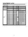
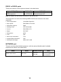
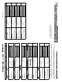
EQUIPMENT LISTS
Standard supply
Name
Display unit
Antenna unit
Remote
controller set
Installation
materials
Type
RDP-148
RSB-110-070-A
RSB-0071-058
Code No.
-
Qty
1
1
1
RMC-100
000-089-885
1
CP03-22200
000-089-887
1
CP03-22100
000-089-848
CP03-22110
000-089-849
CP03-22120
000-089-850
CP03-22130
000-089-851
CP03-22140
000-089-852
CP03-22300
000-089-888
CP03-22310
000-089-889
CP03-22320
000-089-900
CP03-22330
000-089-914
CP03-20301
008-440-670
1
CP03-18001
008-478-740
1
SP03-15201
008-547-740
1
1
1
Spare parts
ii
Remarks
For MODEL1724C
For MODEL 1734C
Remote controller, vinyl case,
battery, labels
For display unit
For MODEL 1724C antenna unit,
5 m signal cable S03-87-5
For MODEL 1724C antenna unit,
10 m signal cable S03-87-10
For MODEL 1724C antenna unit,
15 m signal cable SO3-87-15
For MODEL 1724C antenna unit,
20 m signal cable SO3-87-20
For MODEL 1724C antenna unit,
30 m signal cable S03-87-30
For MODEL 1734C antenna unit,
10 m signal cable S03-88-10
For MODEL 1734C antenna unit,
15 m signal cable SO3-88-15
For MODEL 1734C antenna unit,
20 m signal cable S03-88-20
For MODEL 1734C antenna unit,
30 m signal cable S03-88-30
For antenna unit of
MODEL 1724C
For antenna unit of
MODEL 1734C
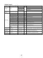
Optional supply
Name
Rectifier
PR-62
External
buzzer
OP03-136
Code No.
000-013-484
000-013-485
000-013-486
000-013-487
000-086-443
MJ-A6SPF0014-010C
MJ-A6SPF0014-050C
MJ-A6SPF0014-100C
MJ-A6SPF0014-200C
MJ-A6SPF0014-300C
MJ-A6SPF0012-050C
MJ-A6SPF0012-100C
MJ-A6SPF0003-050C
MJ-A6SPF0009-100C
MJ-A6SPF0007-100C
000-154-027-10
000-154-049-10
000-154-050-10
000-154-051-10
000-154-052-10
000-154-053-10
000-154-037-10
000-154-054-10
000-154-036-10
000-159-695-10
1
1
1
1
1
1
1
1
1
1
MJ-A7SPF0007-050C
000-154-02810
1
MJ-A6SRMD/TM11AP
8-005
000-144-463
1
For NavNet, 1 m
For NavNet, 5 m
For NavNet, 10 m
For NavNet, 20 m
For NavNet, 30 m
For navaid, 5 m
For navaid, 10 m
w/6P connector, 5 m
w/6P connector, 10 m
For compass, 10 m
For external buzzer/PC,
w/7P connector, 5 m
Adapter cable for HUB
RMC-100
000-089-885
1
Remote controller, vinyl case, battery, labels
OP03-92
008-445-070
1
For MODEL1734C antenna unit
OP03-93
008-445-080
1
For MODEL1724C antenna unit
Cable assy.
Remote
controller set
Mounting
bracket (1)
Mounting
bracket (2)
AIS Interface
Type
IF-1500AIS
Qty
1
Remarks
For 100 VAC
For 110 VAC
For 220 VAC
For 230 VAC
1
For connection of FA-100
iii
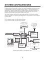
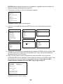
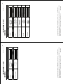
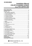
SYSTEM CONFIGURATIONS
All NavNet products incorporate a “network circuit board” to integrate each NavNet product
on board through an optional LAN cable (Ethernet 10BASE-T). Each NavNet product is
assigned an IP address to enable transfer of images between other NavNet products. For
example, video plotter pictures can be transferred to a radar and vice versa. Pictures
received via the NavNet may be adjusted at the receiving end.
The number of display units which may be installed depends on the number of network
sounder connected. For a system incorporating three or more products, a “hub” is required
to process data.
For one network sounder: one radar and three plotters
For two network sounder: one radar and two plotters
Antenna Unit
(ex. MODEL 1724C)
Display Unit
RDP-148
AIS transponder
Echo sounder*
Navigator*
External buzzer
PC
Heading sensor
AIS Interface
IF-1500AIS*
* Not required
for AIS Transponder
FA-150.
* NMEA sentence only
Remote
Controller
RMC-100
Other NavNet unit
(GD-1720C, etc.)
GPS receiver
GP-320B/330B
or
Weather station
WS-200
HUB
Rectifier
PR-62
Network sounder
ETR-6/10N
ETR-30N
12-24 VDC
NavNet2 system MODEL 1724C/MODEL 1734C
iv
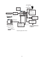
FA-30
AIS RECEIVER
GPS receiver
GP-320B/330B
or
Weather station
WS-200
Remote
Controller
RMC-100
AIS transponder
Echo sounder*
Navigator*
External buzzer
PC
Heading sensor
AIS Interface
IF-1500AIS*
* Not required for
AIS Transponder
FA-150.
* NMEA sentence only
HUB
FA-30
AIS RECEIVER
Display unit
RDP-148
Rectifier
PR-62
Other NavNet Unit
(Model 1724C, etc.)
Network
Sounder
ETR-6/10N
ETR-30N
12 - 24 VDC
: Standard
: Option
: Local supply
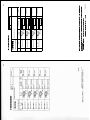
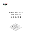
Navnet2 system GD-1720C
v
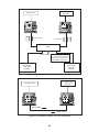
GP-320B/330B,
WS-200
Antenna Unit
Radar data
Plotter data
HUB
Sounder data
Network Sounder
ETR-6/10N
ETR-30N
(option)
Note: The picture disappears
10 seconds after the NavNet
cable is disconnected from a
"sub" NavNet display unit.
Network Sounder
ETR-6/10N
ETR-30N
(option)
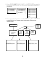
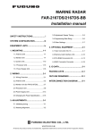
Figure 2 (a) NavNet2 system, three-unit connection
GP-320B/330B,
WS-200
Antenna Unit
Radar data
Plotter data
Figure 2 (b) NavNet2 system, two-unit connection
vi
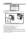
1. MOUNTING
NOTICE
Do not apply paint, anti-corrosive
sealant or contact spray to coating or
plastic parts of the equipment.
Those items contain organic solvents that
can damage coating and plastic parts,
especially plastic connectors.
1.1 Installation of Display Unit
The display unit can be installed on a tabletop, on the overhead or flush mounted in a
console or panel.
Overhead
Tabletop
Hard Cover
Tabletop, overhead mounting method
When selecting a mounting location for the display unit keep the following in mind:
•
•
•
•
•
•
•
Keep the display unit out of direct sunlight.
The temperature and humidity should be moderate and stable.
Locate the unit away from exhaust pipes and vents.
The mounting location should be well ventilated.
Mount the unit where shock and vibration are minimal.
Keep the unit away electromagnetic field generating equipment such as motor, generator.
For maintenance and checking purposes, leave sufficient space at the sides and rear of
the unit and leave slack in cables.
• A magnetic compass will be affected if the display unit is placed too close to the magnetic
compass. Observe the compass safe distances show in the Safety Instructions to prevent
disturbance to a magnetic compass.
1
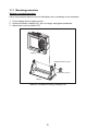
1.1.1 Mounting procedure
Tabletop, overhead mounting
Follow the procedure below to mount the display unit on a tabletop or the overhead.
1. Fix the hanger by four tapping screw.
2. Screw knob bolts in display unit, set it to hanger, and tighten knob bolts.
3. Attach hard cover to protect LCD.
Display unit
Tapping screws (4 pcs.)
Knob bolts (2 pcs.)
Hanger
Tabletop, overhead mounting of display unit
2
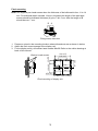
Flush mounting
Note: Use supplied pan head screws when the thickness of the bulkhead is from 11 to 14
mm. For bulkhead which exceeds 14 mm in thickness the length of the pan head
screws should be bulkhead thickness (A) plus 7.3±1.5 mm. Also the length of B
should be max. 7 mm.
B A
Fixing screw, side view
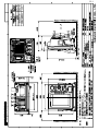
1. Prepare a cutout in the mounting location whose dimensions are as shown in below.
2. Attach the flush mount sponge to the display unit.
3. Fix the display unit by six washer head screws M4x20. Refer to the outline drawing at
back of this manual.
50
186±1
42±0.5
130 ±0.5
208 ±1
6-R2.25
Flush mounting of display unit
3
198 ±1
97 ±0.5
206 ±0.5
110 ±0.5
Washer head screws
1.2 Mounting of Antenna Units
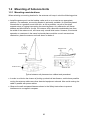
1.2.1 Mounting considerations
When selecting a mounting location for the antenna unit keep in mind the following points.
• Install the antenna unit on the hardtop, radar arch or on a mast on an appropriate
platform. (For sailboats, a mounting bracket is optionally available.) It should be placed
where there is a good all-round view with, as far as possible, no part of the ship's
superstructure or rigging intercepting the scanning beam. Any obstruction will cause
shadow and blind sectors. A mast, for instance, with a diameter considerably less than
the width of the antenna unit, will cause only a small blind sector. However, a horizontal
spreader or crosstrees in the same horizontal plane would be a much more serious
obstruction; place the antenna unit well above or below it.
Antenna unit
Antenna unit
Antenna unit
Antenna unit
Typical antenna unit placement on sailboat and powerboat
• In order to minimize the chance of picking up electrical interference, avoid where possible
routing the antenna cable near other electrical equipment onboard. Also avoid running the
cable in parallel with power cables.
• Observe the safe compass distances shown in the Safety Instructions to prevent
interference to a magnetic compass.
4
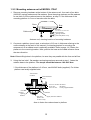
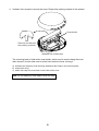
1.2.2 Mounting antenna unit of MODEL 1724C
1. Remove mounting hardware at the bottom of the antenna unit; four each of hex bolts
(M10X20), spring washers and flat washers. Save the spring washers and flat washers
to use them to fix the radome base to the platform, at step 3. If the thickness of the
mounting platform is 5 mm or less also save the bolts.
Stern
Bow
Screws
two screws on other side
Cable entry
Flat washer
Spring washer
Hex bolt (M10 x 20)
Antenna unit, showing location of mounting hardware
2. Construct a platform (wood, steel, or aluminum) 6-10 mm in thickness referring to the
outline drawing at the back of this manual. (A mounting bracket for mounting the
antenna unit on a sailboat mast is optionally available. Refer to page 14.) Fasten the
platform to the mounting location. Next, position the base so the cable entrance faces
the stern direction.
Note: When drilling holes in the platform, be sure they are parallel with the fore and aft line.
3. Using the hex bolts*, flat washers and spring washers removed at step 1, fasten the
radome base to the platform. The torque should be between 19.6-24.5 N•m.
* If the thickness of the platform is 6-10 mm, use M10x25 bolts (supplied). For thicker
platform use locally supplied bolts.
Transceiver
module
Antenna base
assy.
5 mm or under: M10x20
6-10 mm:
M10x25
over 10 mm:
localy supplied bolts
Flat
washer
Spring
washer
Platform
Hex bolt
Apply silicone sealant.
(M10 x 25
or M10 x 20)
How to fasten the radome base to platform
5
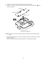
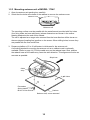
4. Unfasten four screws to remove the cover. Discard the packing material in the radome.
Snap holder
Remove and discard
the packing material.
Antenna unit, inside view
The mounting base is fitted with a snap holder, which may be used to hang the cover
after removal. Use the hole next to screw hole inside the cover to hang it.
a) Unfasten the snap assy. with the string attached at the holder in the mounting base.
b) Unwind the string.
c) Attach the snap to a screw hole on the inside of the cover.
Note: Do not hang any other objects with the snap.
6
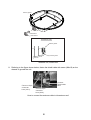
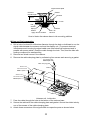
5. Unfasten the cable of the rotation detector from the cable clamps.
6. Unfasten 11 screws to dismount the shield plate. Discard screw marked with
figure shown below.
in the
Cable clamp
Shield plate
Rotation detector
Caution
Antenna unit, inside view
Caution: Be careful not to pinch the rotation detector cable when remounting the shield
plate.
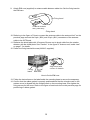
7. Pass the antenna cable with connector through the gasket and cable clamp, and then
tighten cable gland.
Be sure the shrink tubing on the antenna cable is not covered by the gasket.
7
Rubber gasket
Gasket
Cable Gland
Sectional view
Rubber gasket
Mounting base
Antenna unit, inside view
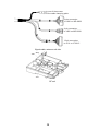
8. Referring to the figure shown below, fasten the shield cable with screw (M4x10) on the
chassis to ground the unit.
Connect 10 pin
connector
here (J811).
Connect
shield cable
here.
Connect 9 pin
connector
here (J801).
How to connect the antenna cable to the antenna unit
8
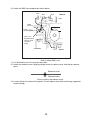
9. Attach EMI core (supplied) to antenna cable between cable ties. Set the fixing band to
the EMI core.
Fixing band
This bend should be
facing cable entry.
Fixing band
10. Referring to the figure of "How to connect the antenna cable to the antenna Unit" on the
previous page connect the 9-pin (J801) and 10-pin (J811) connectors of the antenna
cable to the INT Board.
11. Refasten the shield plate with 10 screws. Be sure not to pinch cable from the rotation
detector with the shield plate. See "Caution" in the figure of "Antenna unit, inside view"
on page 7, for details.
12. Fasten the fixing band with screw (M4X15; supplied).
Screw(M4X15)
Align bend with
corner of chassis.
Fixing
band EMI core
How to fix the EMI core
13. Follow the instructions on the label inside the mounting base to secure the snap assy.
14. Confirm that the rubber gasket is properly positioned and that the triangle mark on the
radome cover is aligned with the triangle mark on the mounting base, then tighten the
fixing screws for the cover. Refer to the figure of sectional view on the previous page for
positioning of rubber gasket.
9
1.2.3 Mounting antenna unit of MODEL 1734C
1. Open the antenna unit packing box carefully.
2. Unbolt the four bolts at the base of the radome to remove the radome cover.
Radome cover
Antenna unit
The mounting surface must be parallel with the waterline and provided with five holes
(four fixing holes and one cable entry) whose dimensions are shown in the outline
drawing attached at the end of this manual.
The unit is adjusted so a target echo returned from the bow direction will be shown on
the zero degree (heading line) position on the screen. When drilling holes, be sure they
are parallel with the fore and aft line.
3. Prepare a platform of 5 to 10 millimeters in thickness for the antenna unit.
A mounting bracket for mounting the antenna unit on a sailboat mast is optionally
available. (Refer to page 14.) Find the cable entry on the radome base. Next, position
the radome base so the cable entry faces the stern direction. This alignment must be as
accurate as possible.
Ship's bow
Cable
entry
4- 12 Holes
Flat washer
Spring washer
M10 x 25 Hex bolt
Platform
Antenna unit, cover removed
10
Antenna base plate
Effective
thread length
Gasket
Radome
25 mm
5 - 10 mm
Flat
washer
Spring
washer
Apply silicone sealant.
Platform
M10 x 25
Hex bolt
How to fasten the radome base to the mounting platform
Wiring and final preparation
4. Drill a hole of at least 20 millimeters diameter through the deck or bulkhead to run the
signal cable between the antenna unit and the display unit. (To prevent electrical
interference avoid running the signal cable near other electrical equipment and in
parallel with power cables.) Pass the cable through the hole. Then, seal the hole with
sealing compound for waterproofing.
5. Remove two shield covers in the radome.
6. Remove the cable clamping plate by unfastening four screws and removing a gasket.
Pan head screws
M4x8 4 pcs.
Cable clamping plate
Shield cover
Gasket
Pan head screws
M4x8 7 pcs.
Shield cover
Pan head screws
M4x8 7 pcs.
Antenna unit, inside view
7. Pass the cable through the hole at the bottom of the radome base.
8. Secure the cable with the cable clamping plate and gasket. Ground the shield wire by
one of the screws of the cable clamping plate.
9. Attach three connectors of the signal cable to respective ports as shown below.
11
to one of the screws
of the cable clamping plate
9-pin connector:
to J801 on MD-9208
4-pin connector:
to J802 on MD-9208
13-pin connector:
to J611 on IF-9215
Signal cable, antenna unit side
J802
J801
J611
RF unit
12
10. Attach the EMC core supplied as shown below.
J801
J802
J805
MD9208
J804
J806
J803
Cable
entrance
Cable
clamping plate
Motor
EMC core
E04SS251512
(Above cable
clamping
plate)
J1
J613
PTU-9335
J611
IF9215
How to attach EMC core
11. Fix the shield cover. Do not pinch the cable.
12. Attach the radome cover, aligning triangle mark on radome cover with that on radome
base.
Radome cover
Radome base
How to position the radome cover
13. Loosely fasten the radome fixing bolts. You will tighten them after confirming magnetron
heater voltage.
13
1.2.4 Mounting the optional mounting bracket
A mounting bracket for fastening the antenna unit to a mast on a sailboat is optionally
available.
Mounting bracket 1 (for MODEL 1734C)
Type:
OP03-92
Code No.: 008-445-070
Part
Type
Code No.
Qty
Hex. bolt
M4X12
000-804-725
4
Hex. bolt
M8X20
000-805-707
8
Mounting plate
03-018-9001-0
100-206-740
1
Support plate (1)
03-018-9005-0
100-206-780
1
Support plate (2)
03-018-9006-0
100-206-790
1
Bracket (1)
03-018-9002-1
100-206-751
1
Bracket (2)
03-018-9003-1
100-206-761
1
Fixing plate
03-018-9004-1
100-206-771
2
Mounting bracket 2 (for MODEL 1724C)
Type:
OP03-93
Code No.: 008-445-080
Part
Type
Code No.
Qty
Hex. bolt
M4X12
000-804-725
4
Hex. bolt
M8X20
000-805-707
8
Mounting plate
03-018-9001-0
100-206-740
1
Support plate (1)
03-018-9005-0
100-206-780
1
Support plate (2)
03-018-9006-0
100-206-790
1
Bracket (1)
03-028-9101-0
100-206-810
1
Bracket (2)
03-028-9102-0
100-206-820
1
Fixing plate
03-028-9103-0
100-206-830
2
Assemble the mounting bracket and fasten it to a mast. Fasten the antenna unit to the
bracket.
14
Support plate
(A) Assembling the mounting bracket
(B) Fastening antenna to mounting
bracket
How to assemble and mount the optional mounting bracket
15
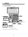
2. WIRING
2.1 Standard Wiring
All wirings are terminated at the rear of the display unit.
CAUTION
The power cable is shipped with a 10A fuse
(5A on GD-1720C) inserted in its fuse holder.
This fuse is for use with a 12 VDC power supply.
If you are using a 24 VDC power supply, replace
the fuse with a 5A fuse (3A fuse on GD-1720C).
Also, attach the "5A label" ("3A label" on GD-1720C)
to the fuse holder on the power cable. Use of an
improper fuse can result in damage to the equipment.
12-24 VDC
Connect power
cable here.
Signal cable connector
Connect signal cable
from antenna here.
NOTICE
Tighten the boot-band
securely to ensure
watertightness.
Ground terminal
Connect ground wire between
here and ship's ground.
CAUTION
Ground the
equipment to
prevent
interference.
DATA 3 (7P)
Connect external
buzzer (option),
PC here.
DATA 1 (7P)
Connect
GPS receiver
GP-310B/320B,
NMEA equipment,
AIS Transponder/Interface
here.
DATA 2 (6P)
Connect heading
sensor here.
(AD or NMEA format)
NETWORK (6P)
Connect other NavNet
equipment (GD-1720C,
ETR-6/10N, ETR-30N,
HUB etc.) here.
Display unit, rear view
For signal cable connection, see the procedure on the next page.
16
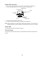
Signal cable connection
1. Remove the waterproofing cover from the DJ-1 at the back of the display unit.
2. Connect the signal cable to DJ-1 on the rear panel of the display unit.
Rubber cover
DJ Connector
Cable
Boot-band
DJ-1
Display unit
3. Cover the connector with the rubber cover.
4. Put the boot-band as shown above, and fasten four screws to fix.
Note: When the display unit is used without signal cable connection, do not remove the
waterproofing cover. Wrap the display unit and waterproofing cover with vinyl tape.
Power cable
Connect the power cable to the power connector.
Ground terminal
Connect the ground wire (local supply, IV-2sq) between the ground terminal and ship’s
ground.
17
DATA1 to DATA3 ports
These ports connect to the equipment shown in the table below.
DATA1 (7P)
DATA2 (6P)
DATA3 (7P)
GPS receiver GP-310B/320B,
Heading sensor
RS-232C OUT, NMEA 0183 IN,
NMEA equipment
(ex. SC-60/120) External buzzer OUT
Note: No sensor can be directly connected to the DATA3 port.
This equipment can receive the following NMEA 0183 format sentences from other
equipment.
• Own ship’s position:
GGA>RMC>RMA>GLL
• Ship’s speed:
RMC>RMA>VTG>VHW
• Destination waypoint:
RMB
• Heading (True):
HDT>HDG>HDM
• Course:
RMC>RMA>VTG
• Depth:
DPT>DBT
• Temperature:
MTW
• Time:
ZDA
• Other ship’s information:
TTM
• Insight satellite information:
GSV
• Wind speed and angle:
MWV>VWT>VWR
NETWORK port
This port connects other NavNet equipment, with the optional NavNet cable. Available
equipment are shown in the table below.
Radar
MODEL1724C/1734C
Plotter
Network sounder
ETR-6/10
ETR-30N
GD-1720C
18
Other
HUB (used when more
than two NavNet units
are connected.)
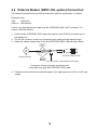
2.2 External Buzzer (OP03-136, option) Connection
The optional external buzzer provides a louder alert when the guard alarm is violated.
External buzzer
Type:
OP03-136
Code no.: 000-086-443
Further, you need the optional cable assy MJ-A7SPF0007-050C (w/7P connector, 5 m,
code no. 000-154-028-10).
1. Attach the MJ-A7SPF0007-050C cable assy (option) to the DATA 3 port at the rear of
the display unit.
2. Cut the XH connector at the end of external buzzer cable with appropriate length.
3. Solder the cables made at step 2 with MJ-A7SPF0007-050C cable as shown below.
Red
Soldering
MJ-A7SPF0007-050C
External buzzer
Black
Cut other cable, and wrap here with tape.
Connection of external buzzer and display unit
using cable assy type MJ-A7SPF0007-050C cable
4. Fasten the buzzer with the double-sided tape or two tapping screws (3x15 or 3x20, local
supply).
19
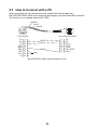
2.3 How to Connect with a PC
When connecting with the personal computer, prepare the optional cable assy
MJ-A7SPF0007-050C and D-sub 9 pins plug (local supply), and connected them as follows.
This function is not available with the GD-1720C.
SHIELD
BLUE
WHITE
5
1
9
6
MJ-A7SPF0007-050C
D-SUB 9PIN
CD
RD
TD
DTR
GND
DSR
RTS
CTS
RI
1
2
3
4
5
6
7
8
9
WHITE
BLUE
SHIELD
short
1
2
3
4
5
6
7
TD
RD
RD_A
RD_B
+12V
EXT BUZZ
GND
MJ-A7SPF0007-050C cable connection for PC
20
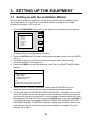
3. SETTING UP THE EQUIPMENT
3.1 Setting up with the Installation Wizard
After you have installed the equipment, set up the equipment with the installation wizard.
The wizard allows you to easily set up the NavNet network (choose source of radar,
sounder and auxiliary), GPS, ports, etc.
1. Press the POWER/BRILL key to turn on the power, and the following screen appears.
INSTALL
WIZARD
LANGUAGE
▲
NEXT
~
ENGLISH
{ FRANCAIS
{ DEUTSH
{ ITALIANO
{ PORUTGES
{ ESPANOL
{ DANSK
{ SVENSKA
{ NORSK
▼
ENTER
EXIT
Installation wizard, language selection window
2. Rotate the ENTER knob to choose the appropriate language and then push the ENTER
soft key.
3. A dialog box asks you if you want to start the simulation mode, which provides
simulated operation of the equipment.
4. Press the CLEAR key to skip the simulation mode. Then, the SELECT MODE window
appears.
SELECT MODE
▲
~
INST. WIZARD
INST. MODE
{ SIMPLE CHECK MODE
{ NORMAL MODE
▼
{
CHANGE OR CONFIRM THE ITEMS SHOWN
ABOVE. THEN PUSH [NEXT] WHEN DONE.
5. Confirm that INST. WIZARD is selected, and then push the ENTER soft key. A
diagnostic test is conducted and then the chart disclaimer message appears.
6. You are then asked “LOAD SETTING DATA FROM CARD?”. This allows you to use the
set up this NavNet unit with the settings of another NavNet unit, thereby shortening the
time required to set up the equipment. To use the settings of another NavNet unit, insert
the appropriate SD card in the slot and push the ENTER knob. If not, hit the CLEAR key.
If you loaded settings, the message “LOADING COMPLETED. REMOVE THE CARD
AND PRESS ANY KEY TO RESTART” appears if loading was successful. Remove the
card and press any key to restart the equipment; installation is completed. To set up
manually, go to step 7.
21
CAUTION: Ensure that the settings to be loaded are compatible with this NavNet unit.
Improper settings will damage the equipment.
7. The screen for set up of units of measurement appears.
RANGE UNIT
nm, kt
DEPTH UNIT
ft
TEMPERATURE UNIT
°F
WIND UNIT
kt
LOCAL TIME OFFSET
+00:00
AIR PRESSURE UNIT
hpa
Installation wizard, units of measurement
8. Choose an item and then press the EDIT soft key. One of the following windows
appears.
RANGE/SPEED UNIT
DEPTH UNIT
TEMPERATURE UNIT
▲
▲
▲
{
{
{
nm, kt
~ km, km/h
{ sm, mph
{ nm & yd, kt
{ nm & m, kt
{ km & m, km/h
{ sm & yd, mph
▼
m
~ ft
{ fa
{ PB
▼
~
°C
°F
▼
AIR PRESSURE UNIT
LOCAL TIME OFFSET
▲
{
hpa
mbar
{ mmHg
{ inHg
▼
WIND UNIT
▲
~
+ 00:00
{
kt
~ km/h
{ MPH
{ m/s
▼
9. Choose unit of measurement desired and then press the ENTER soft key. LOCAL TIME
OFFSET allows you to use local time (instead of UTC time). Set the time difference
between local time and UTC time.
10. After you have chosen units of measurement, press the NEXT soft key, and the
NETWORK SETUP menu appears. This is where you set up your NavNet network. See
the illustration on then next page for typical network setup. If you have no other
NavNet devices installed, press the NEXT key and go to step 13.
DEVICE NUMBER
1
(HOST NAME
(IP ADDRESS
NAVNET1)
172.031.003.003)
RADAR SOURCE
1
SOUNDER SOURCE
ETR0
FOR FURTHER DETAILS,
PLEASE REFER TO THE
INSTALLATION MANUAL
Installation wizard, network setup
22
11. Choose DEVICE NUMBER, RADAR SOURCE or SOUNDER SOURCE as appropriate
and then press the EDIT soft key. One of the following displays appears depending on
your selection.
RADAR SOURCE
DEVICE NUMBER
▲
▲
{
{
1 (IP:172.031.003.001)
~ 2 (IP:172.031.003.002)
{ 3 (IP:172.031.003.003)
{ 4 (IP:172.031.003.004)
▼
SOUNDER SOURCE
▲
{
~
{
{
{
{
{
{
{
{
{
1 (IP:172.031.003.001)
~ 2 (IP:172.031.003.002)
{ 3 (IP:172.031.003.003)
{ 4 (IP:172.031.003.004)
{ NO CONNECT
▼
▼
ETR0 (IP:172.031.092.001)
ETR1 (IP:172.031.092.011)
ETR2 (IP:172.031.092.012)
ETR3 (IP:172.031.092.013)
ETR4 (IP:172.031.092.014)
ETR5 (IP:172.031.092.015)
ETR6 (IP:172.031.092.016)
ETR7 (IP:172.031.092.017)
ETR8 (IP:172.031.092.018)
ETR9 (IP:172.031.092.019)
OFF
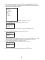
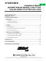
12. Choose appropriate setting and then press the ENTER soft key. If you set DEVICE NO.
or RADAR SOURCE, turn the power on and off again at the completion of the
installation wizard.
Radar Antenna
Echo
Sounder
ETR0
(default)
HUB
7-inch Display
Device 1
7-inch
display
Device 2
7-inch
display
Device 3
FAX30
AUX1
(default)
Device Number - 1
Device Number - 2
Device Number - 3
Radar Source - 1
Radar Source - 1
Radar Source - 1
Sounder Source - ETR0
Sounder Source - ETR0
Sounder Source - ETR0
Aux Source - AUX1
Aux Source - AUX1
Aux Source - AUX1
23
13. After choosing ALL sources, press the NEXT soft key, and the RADAR SETUP menu
appears. If you do not have a radar installed, press the NEXT soft key to show the
NAV SETUP menu and go to step 25.
ANTENNA TYPE
A
HEADING DATA
MAGNETIC
ANTENNA ROTATION
ROTATE
TUNING
OFF
TIMING ADJUST
OFF
HEADING ADJUST
OFF
Installation wizard, radar setup
14. Choose ANTENNA TYPE and then press the EDIT soft key.
ANTENNA TYPE
▲
{
~
▼
A (MODEL 1724C)
B (MODEL 1734C)
15. Choose the appropriate antenna type and then press the ENTER soft key.
16. Choose HEADING DATA and then press the EDIT soft key.
HEADING DATA
▲
{
~
MAGNETIC
TRUE
▼
17. Choose the appropriate heading data source and then press the ENTER soft key. Select
MAGNETIC when connecting with a magnetic compass, or select TRUE when
connecting with a gyrocompass or satellite compass.
18. Choose ANTENNA ROTATION and then press the EDIT soft key.
ANTENNA ROTATION
▲
~
{
▼
ROTATE
STOP
19. Confirm that ROTATE is selected and then press the ENTER soft key.
24
20. Choose TUNING and then press the EDIT soft key.
TUNING
▲
{
~
ON
OFF
▼
21. Choose ON and then press the ENTER soft key. Then, the radar’s video and tuning are
automatically adjusted.
22. After tuning has been completed, choose TIMING ADJUST and then press the EDIT
soft key.
TIMING ADJUST
▲
{
~
ON
OFF
▼
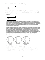
This adjustment ensures proper radar performance, especially on short ranges. The
radar measures the time required for a transmitted echo to travel to the target and return
to the source. The received echo appears on the display based on this time. Thus, at the
instant the transmitter is fired, the sweep should start from the center of the display
(sometimes called sweep origin.)
A trigger pulse generated in the display unit goes to the antenna unit through the signal
cable to trigger the transmitter (magnetron). The time taken by the signal to travel up to
the antenna unit varies, depending largely on the length of signal cable. During this
period the display unit should wait before starting the sweep. When the display unit is
not adjusted correctly, the echoes from a straight local object (for example, a harbor wall
or straight pier) will not appear with straight edges – namely, they will be seen as
“pushed out” or “pulled in” near the picture center. The range of objects will also be
incorrectly shown.
(1) Target
pulled
(2) Correct
(3) Target pushed
outward
Examples of improper and correct sweep timing
a)
b)
c)
d)
Choose ON and then press the ENTER soft key.
Transmit on the shortest range and confirm that gain and A/C SEA are properly adjusted.
Visually select a target which forms straight line (harbor wall, straight piers).
Rotate the ENTER knob to straighten the target selected at step b), and then press the
ENTER knob to finish.
25
23. Choose HEADING ADJUST and then press the EDIT soft key.
HEADING ADJUST
▲
{
~
ON
OFF
▼
24. Choose ON and then press the ENTER soft key.
You have mounted the antenna unit facing straight ahead in the direction of the bow.
Therefore, a small but conspicuous target dead ahead visually should appear on the
heading line (zero degrees).
In practice, you will probably observe some small error on the display because of the
difficulty in achieving accurate initial positioning of the antenna unit. The following
adjustment will compensate for this error.
a) Set ship’s heading toward a suitable target (for example, ship or buoy) at a range between
0.125 and 0.25 nautical mile.
b) Rotate the ENTER knob to bisect the target with the EBL and press the SET soft key.
c) Press the RETURN soft key.
d) As a final test, move the boat towards a small buoy and confirm that the buoy shows up dead
ahead on the radar when it is visually dead ahead.
25. The next step is to choose navigation data sources and calibrate navigation data. Press
the NEXT soft key to show the NAV SETUP menu.
POSITION SOURCE
FURUNO BB GPS
SPEED (STW) SOURCE
ETR
TEMPERATURE SOURCE
ETR
DETPH SOURCE
ETR
STW CALIBRATION
+00%
TEMP CALIBRATION
+00.0°F
DEPTH CALIBRATION
+00ft
WIND AVERAGING
001 seconds(s)
WIND DIRECTION OFFSET
S000.0°
WIND SPEED CALIBRATION
+00%
WIND (MWV) SOURCE
FURUNO BB GPS
STW
TEMP
12.3 kt
56.3°F
WIND SPEED
1.2 kt
DEPTH
WIND DIR
99.5ft
131°
AIR TEMPERATURE SOURCE
FURUNO BB GPS
AIR PRESSURE SOURCE
FURUNO BB GPS
STW
12.3 kt
WIND SPEED
1.2 kt
DEPTH
99.5ft
Page 1
TEMP
56.3°F
WIND DIR
Page 2
131°
Installation wizard, nav setup
26. Choose appropriate item and press the EDIT soft key.
27. Choose appropriate setting and then press the ENTER soft key. Refer to the table below
for description of each item.
26
NAV SETUP menu description
Item
Position
Source
Description
Chooses source of position data.
Speed (STW)
Source
Temperature
Source
Chooses source of speed data
Depth
Source
Chooses source of depth data.
STW
Calibration
Temp
Calibration
Depth
Calibration
Wind
Averaging
Calibrates NMEA speed data. Enter amount
in percentage.
Calibrates NMEA temperature data. Enter
offset to correct NMEA temperature data.
Calibrates NMEA depth data. Enter offset to
correct NMEA depth data.
Enter a value to smooth wind
speed/direction data. Ship’s bow is
referenced to smooth wind vector
movement.
Offsets wind direction data.
Wind
Direction
Offset
Wind Speed
Calibration
Wind (MWV)
Source
Chooses source of water temperature data.
Offsets NMEA wind speed data. Enter
amount in percentage.
Chooses source of wind data.
Air
Temperature
Source
Chooses source of air temperature data.
Air Pressure
Source
Chooses source of air pressure data.
27
Settings (Default in bold)
FURUNO BB GPS: GPS Receiver
GP-320B/330B or Weather sensor
WS-200
GP: GPS navigator (via
NETWORK or NMEA port)
LC: Loran C navigator (via
NETWORK or NMEA port)
ALL: Multiple navaid connection
(via NETWORK or NMEA port)
ETR (NavNet sounder), NMEA
ETR, NMEA. Select ETR to show
water temperature data fed from
the network sounder.
ETR, NMEA. Select ETR to show
depth data fed from the network
sounder.
-50 to +50%, 00%
-20.0°C to +20.0°C (or equivalent
in °F), 00.0°C
-15 to +90 ft (or equivalent in m, fa
or P/B). 00 ft
001-600 s, 001 s
S180°-P180°, S000.0°
-50 to +50%, 00%
FURUNO BB GPS, NMEA: Select
FURUNO BB GPS to show wind
data fed from the WS-200.
FURUNO BB GPS, NMEA: Select
FURUNO BB GPS to show air
temperature data fed from the
WS-200.
FURUNO BB GPS, NMEA: Select
FURUNO BB GPS to show air
pressure data fed from the
WS-200.
28. After setting up navigation equipment, press the NEXT soft key, and the GPS SETUP
menu appears. This menu sets ups the FURUNO GPS receiver GP-320B/330B. If you
do not have this equipment, press the NEXT soft key and go to step 31.
GEODETIC DATUM
WGS-84
POSITION SMOOTHING
000 second (s)
SPD/CSE SMOOTHING
005 second (s)
LATITUDE OFFSET
0.000'N
LONGITUDE OFFSET
0.000'E
DISABLE SATELLITE
-- -- -LATITUDE
45°35.000'N
LONGITUDE
125°00.000'W
ANTENNA HEIGHT
005 m
GPS FIX MODE
2D/3D
COLD START
NO
Installation wizard, GPS setup
29. Choose an item and press the EDIT soft key to show corresponding window.
30. Choose setting and then press the ENTER soft key. Refer to the table which follows for
description.
GPS SETUP menu description
Item
Description
Settings
Default Setting
Geodetic
Datum
Your equipment is preprogrammed with
most of the major chart systems of the
world. Although the WGS-84 system,
the GPS standard, is now widely used
other categories of charts still exist.
Select the chart system used, not the
area where your boat is sailing.
Use the cursor
pad or ENTER
knob to select
appropriate
chart.
WGS-84
Position
Smoothing
When the DOP or receiving condition is
unfavorable, the GPS fix may change,
even if the vessel is dead in water. This
change can be reduced by smoothing
the raw GPS fixes. A setting between
000 to 999 is available. The higher
setting the more smoothed the raw
data, however too high a setting shows
response time to change in latitude and
longitude. This is especially noticeable
at high ship’ speeds. Increase the
setting if the GPS fix changes.
0-999 sec
0 sec (no position
smoothing)
(Con’t on next page)
28
GPS SETUP menu description (con’t from previous page)
Item
Description
Settings
Default Setting
During position fixing, ship’s velocity
(speed and course) is directly
measured by receiving GPS satellite
signals. The raw velocity data may
change randomly depending on
receiving conditions and other factors.
You can reduce this random variation
by increasing the smoothing. Like with
latitude and longitude smoothing, the
higher the speed and course smoothing
the more smoothed the raw data. If the
setting is too high, however, the
response to speed and course change
slows. For no smoothing, enter all
zeros.
Offsets latitude position to further refine
position accuracy. Use the N <- - > S
soft key to switch coordinate.
0-999 sec
5 sec
9.999’S –
9.999’N
0.0’ (no offset)
Longitude
Offset
As above but for longitude. Use the W
< - - > E soft key to switch coordinate.
9.999’E –
9.999’W
0.0’ (no offset)
Disable
Satellite
Every GPS satellite is broadcasting
abnormal satellite number (s) in its
Almanac, which contains general orbital
data about all GPS satellites, including
those which are malfunctioning. Using
this information, the GPS receiver
automatically eliminates any
malfunctioning satellite from the GPS
satellite schedule. However, the
Almanac sometimes may not contain
this information. If you hear about a
malfunctioning satellite from another
source, you can disable it manually.
Enter satellite number (max. 3
satellites) in two digits and press the
ENTER soft key.
Latitude
Set initial latitude position after cold
start. Use the N < - -> S soft key to
switch coordinate.
90°S - 90°N
45°35.000’N
Longitude
Set initial longitude position after cold
start. Use the W <- - > E soft key to
switch coordinate.
180°E – 180°W
125°00.000W
Antenna
Height
Enter the height of the GPS antenna
unit above sea surface.
0-99 m
5m
Spd/Cse
Smoothing
Latitude Offset
None
(Con’t on next page)
29
GPS SETUP menu description (con’t from previous page)
Item
Fix Mode
Cold Start
Description
Choose position fixing method: 2D
(three satellites in view), 2D/3D (three
or four satellites in view whichever is
greater).
Clears the Almanac to receive the latest
Almanac.
Settings
2D, 2D/3D
Default Setting
2D/3D
No, Yes
No
WAAS setup
Press the WAAS SETUP soft key at the GPS SETUP menu to show the WAAS SETUP
display.
Contents of WAAS SETUP menu
Item
WAAS Mode
WAAS
Search
WAAS Alarm
Corrections
Data
Description
Select ON to use the WAAS mode.
WAAS satellite can be searched
automatically or manually. For manual
search, enter appropriate WAAS satellite
number.
When the WAAS signal is lost, the
audible alarm sounds with the visual
message “NO WAAS SIGNAL.”
On: Alarm continues to sound until the
WAAS positioning mode is available
again or the alarm is recognized by key
operation.
Off: Alarm sounds three times.
Selects the type of message for WAAS
correction. Use “00” (operational status)
in North America; “02” in other locations.
Settings
On, Off
Auto, Manual
Default Setting
Off
Auto
On, Off
Off
00 to 27, 99
02
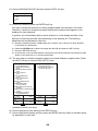
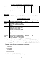
31. After you have finished setting up the GPS receiver GP-320B/330B, it’s now time to set
up external equipment. Press the NEXT soft key to show the DATA1 (GPS/NMEA) port
setup menu. It is only necessary to set up ports which you are going to use; skip
unnecessary steps. If you do not have external equipment connected to the NavNet,
press the NEXT key several times to show the “FINISH AND EXIT INSTALLATION
WIZARD” screen and then push the ENTER knob to finish.
OUTPUT FORMAT
NMEA0183 2.0
BAUD RATE
4800bps
LAT/LON FORMAT
DD°MM.MMM'
XTE FORMAT
X. XX
OUTPUT DESTINATION
NO
Installation wizard, DATA1 (GPS/NMEA) port setup menu
30
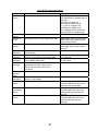
32. Choose item and press the EDIT soft key. Choose appropriate setting and then press
the ENTER soft key. Refer to the table and sentence description on the next page for
details.
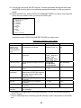
33. Press the NEXT key, and the DATA3 (PC/NMEA/EXT BUZZ) port setup menu appears.
Set up this port similar to how you set up the DATA1 port.
NMEA OUTPUT FORMAT
NMEA Ver 2.0
BAUD RATE
4800bps
BIT LENGTH
8 bits
STOP BIT
1 bit
PARITY
NONE
(Control: Xon/Xoff)
Installation wizard, DATA3 (PC/NMEA/EXT BUZZ) port setup menu
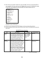
Description of items in “port” menus
Item
Output Format
(DATA1 port),
NMEA Output
Format (DATA3
port)
Baud Rate
Description
Selects NMEA output version for
the equipment connected.
Settings
NMEA0183 Ver. 1.5,
NMEA0183 Ver. 2.0
Default Setting
NMEA0183 Ver.
2.0
Choose baud rate of equipment
connected.
4800
Lat/Lon Format
Selects latitude/longitude format to
output.
XTE Format
DATA1 port:
AUTO*1, 4800 and
38400*2 (bps)
DATA3 port: 4800,
9600, 19200 (bps)
DD°MM.MM’,
DD°MM.MMM’,
DD°MM.MMMM’
X. XX,
X. XXX
Yes, No
Selects number of XTE digits to
X. XX
output.
Selects whether to output route
No
(data sentence RTE) and waypoint
data (data sentence WPL) when
destination is set.
Choose bit length of equipment
7, 8 (bits)
7 bits
connected.
Choose stop bit of equipment
1, 2 (bits)
1 bit
connected.
Choose parity of equipment
Even, Odd, None
None
connected.
Use this key to view which sentences are being output. See the example on
then next page
Output
Destination
Bit Length
Stop Bit
Parity
PORT MNITR
(soft key)
DD°MM.MMM’
*1 Auto detection of baud rate of connected equipment. For use only with device having
“AUTO” feature.
2
* Choose 38400 bps when connecting an AIS Interface or AIS Transponder to the DATA1
port.
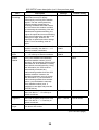
31
$GPGLL,3415.2345,N,13520.5301,E,152500.00
,A*E7<CR><LF>$GPGLL,3415.2345,N,135
20.5301,E,152500.00,A*E7<CR><LF>$GPGLL
,3415.2345,N,13520.5301,E,152500.00,A*
E7<CR><LF>$GPGLL,3415.2345,N,13520.530
1,E,152500.00,A*E7<CR><LF>$GPGLL,3415.
2345,N,13520.5301,E,152500.00,A*E7<CR>
<LF>$GPGLL,3415.2345,N,13520.5301,E,15
2500.00,A*E7<CR><LF
Installation wizard, port monitor display
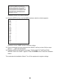
34. Press the NEXT soft key, and the NMEA sentence selection window appears.
AAM
APB
BOD
BWR
DPT
GGA
GLL
GTD
MTW
RMA
RMB
RMC
VHW
VTG
WPL
XTE
ZDA
HDT
HDG
MWV
ZTG
----------------------
Installation wizard, NMEA sentence selection window
35. Choose sentence to process and press the ON/OFF soft key to show ON (to output
data) or “- -“ (OFF) as appropriate.
36. Press the NEXT soft key and the message “FINISH AND EXIT INSTALLATION
WIZARD. ARE YOU SURE?” appears. Press the ENTER knob to finish the installation
wizard.
This concludes the Installation Wizard. Turn off the equipment to register settings.
32
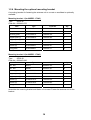
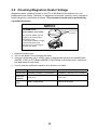
3.2 Checking Magnetron Heater Voltage
Magnetron heater voltage is formed on the PTU or MD Board of the antenna unit, and
preadjusted at the factory. Therefore, no adjustment is required. However, check magnetron
heater voltage for confirmation as follows. This procedure should only be performed by
a qualified technician.
NOTICE
For MODEL1724C,
lift the radome cover slowly.
Screw holes
(4 places)
The antenna radiator may be
caught by the screw holes in
the radome cover.
If you feel the radiator is caught
by the screw holes, lower
the cover, turn it a few degree
and then lift it again.
1. Open the antenna unit.
2. Turn on the power. Do not transmit the radar.
3. Connect a multimeter, set to 10VDC range, to appropriate test point on the MD Board
(MODEL 1724C) or PTU Board (MODEL 1734C) Board in the antenna unit, referring to
the table below for test points.
4. Confirm that the multimeter indication is as shown in the table.
MODEL 1724C
MODEL 1734C
Check point
TP804#6(+) and #4(-) on MD Board
TP802#4(+) and #6(-) on PTU Board
Multimeter
indication
7.9 to 8.1 V
7.4 to 7.6 V
Adjustment
point
VR801 on MD Board
R106 on PTU Board
33
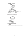
3.3 Remote Controller Setting
A remote controller can be set exclusively for use with a specific display unit, in the case of
multiple NavNet display units. Set the remote controller ID mode desired on the menu and
attach appropriate label (supplied with accessories) to the remote controller and display
unit.
1. Press the MENU key followed by the SYSTEM CONFIGURATION and GENERAL
SETUP soft key to show the GENERAL SETUP menu.
KEY BEEP
ON
LANGUAGE
ENGLISH
RANGE UNIT
nm, kt
TEMPERATURE UNIT
°F
DEPTH UNIT
ft
WIND UNIT
ft
WIND DATA
APPARENT
SPEED AVERAGING
60 seconds
LOCAL TIME OFFSET
9H 0m
RESET TRIP LOG
NO
TIMEOUT DISPLAY SETTING
15 sec
SAVE MOB KEY FUNCTION
SAVE SHIP POSITION & MOB
WALLPAPER
DEFAULT
LAT/LON DISPLAY
DD˚MM.MMMM'
TD DISPLAY
LORAN C
SPEED
SOG
POSITION DISPLAY
LAT/LON
TIME DISPLAY
24 HOURS
INFRARED REMOTE MODE
A
RANGE & BEARING MODE
RHUMB LINE
BEARING READOUT
MAGNETIC
MAGNETIC VARIATION
AUTO 07.0°E
Page 1
Page 2
GENERAL SETUP menu
2. Press the NEXT PAGE soft key to show Page 2.
3. Choose INFRARED REMOTE MODE, and press the EDIT soft key to show the I/R
REMOTE MODE window.
I/R REMOTE MODE
A
B
C
D
MODE
A
Remote controller ID
mode window
PRESS '0' AND '2' KEY
TOGETHER TO CHANGE MODE.
I/R REMOTE MODE window
4. Point the remote controller toward the display unit, and then press any key on the
remote controller. Preset mode appears in the remote controller ID mode window.
5. After the confirmation of the remote controller mode on the window appears, press the
[0] and [2] key together on the remote controller to change the controller ID mode setting
among A, B, C and D.
6. Operate the trackball so that the display ID is the same as the controller mode setting.
7. Press the MENU key to close the menu.
34
0#/'
+056#..#6+10/#6'4+#.5
52#4'2#465
&1%7/'06
/,#52(%
%
'
%2
%2
52
4/%'
4&2'0
&'5%4+26+10%1&'ͳ
㩿㪁㪈㪀
36;
4&2'%5
䯴⇛࿑䬽ኸᴺ䬾䫺ෳ⠨୯䬶䬨䫻䎃䎧䎬䎰䎨䎱䎶䎬䎲䎱䎶䎃䎬䎱䎃䎧䎵䎤䎺䎬䎱䎪䎃䎩䎲䎵䎃䎵䎨䎩䎨䎵䎨䎱䎦䎨䎃䎲䎱䎯䎼䎑䯵
㪉㪅㪞㪛㪄㪈㪎㪉㪇㪚䈪↪ᤨ䇮Ꮏ᧚ᢱ㪚㪧㪇㪊㪄㪉㪉㪉㪇㪈ౝ䈱䍣䍫䍼䍜䍯䍛䍦䍚䍼㪙㩷㪤㪊㪯㪏㩷㪋䍗䈲↪䈚䉁䈞䉖䇯
㪝㪦㪩㩷㪞㪛㪄㪈㪎㪉㪇㪚㪃㪝㪦㪬㪩㩿㪋㪀㩷㪧㪘㪥㩷㪟㪜㪘㪛㩷㪪㪚㪩㪜㪮㪪㩿㪤㪊㪯㪏㪀㩷㪠㪥㩷㪠㪥㪪㪫㪘㪣㪣㪘㪫㪠㪦㪥㩷㪤㪘㪫㪜㪩㪠㪘㪣㪪㩷㪚㪧㪇㪊㪄㪉㪉㪉㪇㪈㩷㪘㪩㪜㩷
㪥㪦㪫㩷㪬㪪㪜㪛㪅
㪈㪅䍘㪄䍢䍼⇟ภᧃየ䈱㪲㪁㪁㪴䈲䇮ㆬᛯຠ䈱ઍဳᑼ㪆䍘䍎䍢䍼䉕䈚䉁䈜䇯
㪚㪦㪛㪜㩷㪥㪬㪤㪙㪜㪩㩷㪜㪥㪛㪠㪥㪞㩷㪮㪠㪫㪟㩷㩹㪁㪁㩹㩷㪠㪥㪛㪠㪚㪘㪫㪜㪪㩷㪫㪟㪜㩷㪚㪦㪛㪜㩷㪥㪬㪤㪙㪜㪩㩷㪦㪝㩷㪩㪜㪧㪩㪜㪪㪜㪥㪫㪘㪫㪠㪭㪜㩷㪤㪘㪫㪜㪩㪠㪘㪣㪅
016+(+%#6+10&1%7/'06
㩕㨷㨺㩇㩨ᄌᦝߩ߅㗿
5+4754'('4'0%'/#07#.
5+4+75ᠲ㩙㩐㨷㨻㩣
࿑ᦠ
+056#..#6+10/#6'4+#.5
Ꮏ᧚ᢱ
%#$.'#55;
㩃㨺㩖㩨㩣⚵ຠ/,
Ꮏ᧚ᢱ
52#4'2#465
੍ຠ
੍ຠ
176.+0'
4'/16'%10641..'45'6
70+6
4'/16'%10641..'45'6
㩢㩝㩄㩧㩈㨹㩎
㩢㩝㩄㩧㩈㨹㩎
&+52.#;70+6
ᜰ␜ㇱ
࡙࠾࠶࠻
㧼㧭㧯㧷㧵㧺㧳ޓ㧸㧵㧿㨀
176.+0'
+/'
15'
1/'
%
&'5%4+26+10%1&'ͳ
36;
䎷䎺䎲䎃䎷䎼䎳䎨䎶䎃䎤䎱䎧䎃䎦䎲䎧䎨䎶䎃䎰䎤䎼䎃䎥䎨䎃䎯䎬䎶䎷䎨䎧䎃䎩䎲䎵䎃䎤䎱䎃䎬䎷䎨䎰䎑䎃䎃䎷䎫䎨䎃䎯䎲䎺䎨䎵䎃䎳䎵䎲䎧䎸䎦䎷䎃䎰䎤䎼䎃䎥䎨䎃䎶䎫䎬䎳䎳䎨䎧䎃䎬䎱䎃䎳䎯䎤䎦䎨䎃䎲䎩䎃
䎷䎫䎨䎃䎸䎳䎳䎨䎵䎃䎳䎵䎲䎧䎸䎦䎷䎑䎃䎴䎸䎤䎯䎬䎷䎼䎃䎬䎶䎃䎷䎫䎨䎃䎶䎤䎰䎨䎑
#9:
ဳᑼ䎒䱤䱚䱮䲈⇟ภ䬛䯾Ბ䬽႐ว䫺ਅᲑ䭗䭙Ბ䬺ઍ䭞䭚ㆊᷰᦼຠ䬶䬑䭙䫺䬸䬰䭘䬚䬛䬲䬵䬓䭍䬨䫻䫹䬹䬙䫺ຠ⾰䬾ᄌ䭞䭙䭍䬪䭢䫻
㪊㪅㩿㪁㪈㪀䈱࿑ᦠ䈲䇮㪚㪄㪤㪘㪧᭽䈱䉂ᔅⷐ䈪䈜䇯
䋨㪁㪈䋩㩷㪚㪄㪤㪘㪧㩷㪪㪧㪜㪚㪠㪝㪠㪚㪘㪫㪠㪦㪥㩷㪦㪥㪣㪰㪅
+056#..#6+10/#07#.
ⵝⷐ㗔ᦠ
12'4#6145)7+&'
ᠲⷐ㗔ᦠ
12'4#6145/#07#.
ขᛒ⺑ᦠ
(.75*/1706+0)6'/2.#6'
㩖㩡㨹㩆㨷㩙㨽㩧㩎ဳ⚕
0#/'
#9: A-1
0#/'
176.+0'
0#/'
176.+0'
/575ޓ
/575
/575
/575
/:575
'55
%2
45$
&'5%4+26+10%1&'ͳ
36;
#2:
#-:
䋨⇛࿑䈱ኸᴺ䈲䇮ෳ⠨୯䈪䈜䇯㩷㩷㪛㪠㪤㪜㪥㪪㪠㪦㪥㪪㩷㪠㪥㩷㪛㪩㪘㪮㪠㪥㪞㩷㪝㪦㪩㩷㪩㪜㪝㪜㪩㪜㪥㪚㪜㩷㪦㪥㪣㪰㪅䋩
#06'00#70+6+056#..#6+10/#6'4+#.5
70+6
#-: 䋨⇛࿑䈱ኸᴺ䈲䇮ෳ⠨୯䈪䈜䇯㩷㩷㪛㪠㪤㪜㪥㪪㪠㪦㪥㪪㩷㪠㪥㩷㪛㪩㪘㪮㪠㪥㪞㩷㪝㪦㪩㩷㪩㪜㪝㪜㪩㪜㪥㪚㪜㩷㪦㪥㪣㪰㪅䋩
524+0)9#5*'4
㩔㩨㩒ᐳ㊄
(.#69#5*'4
㩚㩀㩨㩁ᐔᐳ㊄
*':$1.6
5.166'&*'#&
ⷺ㩇㩢㩦㩢㩘㩨㩣㩎
'/%%14'
'/%㩄㨻
ⓨਛ✢ㇱᎿ᧚
#06'00#70+6
㧔ቢ㧕ⓨਛ✢ㇱ
࡙࠾࠶࠻
45$
㧼㧭㧯㧷㧵㧺㧳ޓ㧸㧵㧿㨀
㪫㪮㪦㩷㪫㪰㪧㪜㪪㩷㪘㪥㪛㩷㪚㪦㪛㪜㪪㩷㪤㪘㪰㩷㪙㪜㩷㪣㪠㪪㪫㪜㪛㩷㪝㪦㪩㩷㪘㪥㩷㪠㪫㪜㪤㪅㩷㩷㪫㪟㪜㩷㪣㪦㪮㪜㪩㩷㪧㪩㪦㪛㪬㪚㪫㩷㪤㪘㪰㩷㪙㪜㩷㪪㪟㪠㪧㪧㪜㪛㩷㪠㪥㩷㪧㪣㪘㪚㪜㩷㪦㪝㩷㪫㪟㪜㩷㪬㪧㪧㪜㪩㩷
㪧㪩㪦㪛㪬㪚㪫㪅㩷㪨㪬㪘㪣㪠㪫㪰㩷㪠㪪㩷㪫㪟㪜㩷㪪㪘㪤㪜㪅
36;
A-2
ဳᑼ㪆䍘䍎䍢䍼⇟ภ䈏䋲Ბ䈱႐ว䇮ਅᲑ䉋䉍Ბ䈮ઍ䉒䉎ㆊᷰᦼຠ䈪䈅䉍䇮䈬䈤䉌䈎䈏䈦䈩䈇䉁䈜䇯䇭䈭䈍䇮ຠ⾰䈲ᄌ䉒䉍䉁䈞䉖䇯
%2
%2
45$#
&'5%4+26+10%1&'ͳ
㪫㪮㪦㩷㪫㪰㪧㪜㪪㩷㪘㪥㪛㩷㪚㪦㪛㪜㪪㩷㪤㪘㪰㩷㪙㪜㩷㪣㪠㪪㪫㪜㪛㩷㪝㪦㪩㩷㪘㪥㩷㪠㪫㪜㪤㪅㩷㩷㪫㪟㪜㩷㪣㪦㪮㪜㪩㩷㪧㪩㪦㪛㪬㪚㪫㩷㪤㪘㪰㩷㪙㪜㩷㪪㪟㪠㪧㪧㪜㪛㩷㪠㪥㩷㪧㪣㪘㪚㪜㩷㪦㪝㩷㪫㪟㪜㩷㪬㪧㪧㪜㪩㩷
㪧㪩㪦㪛㪬㪚㪫㪅㩷㪨㪬㪘㪣㪠㪫㪰㩷㪠㪪㩷㪫㪟㪜㩷㪪㪘㪤㪜㪅
+056#..#6+10/#6'4+#.5
70+6
#2: ဳᑼ㪆䍘䍎䍢䍼⇟ภ䈏䋲Ბ䈱႐ว䇮ਅᲑ䉋䉍Ბ䈮ઍ䉒䉎ㆊᷰᦼຠ䈪䈅䉍䇮䈬䈤䉌䈎䈏䈦䈩䈇䉁䈜䇯䇭䈭䈍䇮ຠ⾰䈲ᄌ䉒䉍䉁䈞䉖䇯
+056#..#6+10/#6'4+#.5
Ꮏ᧚ᢱ
Ꮏ᧚ᢱ
#06'00#70+6
ⓨਛ✢ㇱ
࡙࠾࠶࠻
45$#
㧼㧭㧯㧷㧵㧺㧳ޓ㧸㧵㧿㨀
A-3
A-4
5+)0#.%#$.'#55;
ାภ㩃㨺㩖㩨㩣⚵ຠ
5+)0#.%#$.'#55;
ାภ㩃㨺㩖㩨㩣⚵ຠ
5+)0#.%#$.'#55;
ାภ㩃㨺㩖㩨㩣⚵ຠ
5+)0#.%#$.'#55;
ାภ㩃㨺㩖㩨㩣⚵ຠ
ฬޓޓ⒓
0#/'
⇛ޓޓ࿑
176.+0'
/1&'.%%
%1&'01
5
%1&'01
5
%1&'01
5
%1&'01
5
ဳฬ㧛ⷙᩰ
&'5%4+26+105
ᢙ㊂
36;
ㆬᛯ
61$'5'.'%6'&
ㆬᛯ
61$'5'.'%6'&
ㆬᛯ
61$'5'.'%6'&
ㆬᛯ
61$'5'.'%6'&
↪ㅜ㧛⠨
4'/#4-5
#-: 㧲㨁㧾㨁㧺㧻ޓ㧱㧸㧱㧯㨀㧾㧵㧯ޓ㧯㧻ޓ㧚㧘㧸㨀㧰
㧔⇛࿑ߩኸᴺߪޔෳ⠨୯ߢߔ&ޓޕ+/'05+105+0&4#9+0)(144'('4'0%'10.;㧕
#-:
6916;2'5#0&%1&'5/#;$'.+56'&(14#0+6'/6*'.19'4241&7%6/#;$'5*+22'&+02.#%'1(6*'722'4241&7%6
37#.+6;+56*'5#/'
ဳᑼ㩄㨺㩎㩨⇟ภ߇㧞Ბߩ႐วޔਅᲑࠃࠅᲑߦઍࠊࠆㆊᷰᦼຠߢࠅޔ߅ߥޓޕߔ߹ߡߞ߇߆ࠄߜߤޔຠ⾰ߪᄌࠊࠅ߹ߖࠎޕ
⇟ภ
01
+056#..#6+10/#6'4+#.5
Ꮏ᧚ᢱ
6;2'
%1&'01
A-5
9#5*'4*'#&5%4'9$
㩏㩗㩨㩈㩛㩇$
9#5*'4*'#&5%4'9
㩏㩗㩨㩈㩛㩇$
5'.(6#22+0)5%4'9
㩎㩡㩇㩊㨹㩕㩩㩧㩒㩆㩨ޓ㩆㨷
(.75*/1706+0)5210)'
(㩙㨽㩧㩎㩠㨽㩇㩘㩩㩧㩆㩨
(75'.#$'.
㩕㨷㨺㩇㩨㩔㩢㩙㨺㩂
ฬޓޓ⒓
0#/'
⇛ޓޓ࿑
176.+0'
%1&'
01
/:575
%1&'
01
/:575
%1&'
01
:575
%1&'
01
ޓ41*5
%1&'
01
41*5
ဳฬ㧛ⷙᩰ
&'5%4+26+105
ᢙ㊂
36;
%2
6;2'
↪ㅜ㧛⠨
4'/#4-5
#9: 㧲㨁㧾㨁㧺㧻ޓ㧱㧸㧱㧯㨀㧾㧵㧯ޓ㧯㧻ޓ㧚㧘㧸㨀㧰
㧔⇛࿑ߩኸᴺߪޔෳ⠨୯ߢߔ&ޓޕ+/'05+105+0&4#9+0)(144'('4'0%'10.;㧕
#9:
ဳᑼ㩄㨺㩎㩨⇟ภ߇㧞Ბߩ႐วޔਅᲑࠃࠅᲑߦઍࠊࠆㆊᷰᦼຠߢࠅޔ߅ߥޓޕߔ߹ߡߞ߇߆ࠄߜߤޔຠ⾰ߪᄌࠊࠅ߹ߖ
ࠎޕ
6916;2'5#0&%1&'5/#;$'.+56'&(14#0+6'/6*'.19'4241&7%6/#;$'5*+22'&+02.#%'1(6*'722'4
241&7%637#.+6;+56*'5#/'
⇟ภ
01
+056#..#6+10/#6'4+#.5
Ꮏ᧚ᢱ
%1&'01
A-6
(75'
㩕㨷㨺㩇㩨
(75'
㩕㨷㨺㩇㩨
(75'
㩕㨷㨺㩇㩨
()$18#
2$(
()$18#
2$(
()$18#
2$(
2'4
8'5
5'652'4
8'55'.
4'/#4-5%1&'01
#9:
52#4'
#9: $1:012
㧔⇛࿑ߩኸᴺߪޔෳ⠨୯ߢߔ&ޓޕ+/'05+105+0&4#9+0)(144'('4'0%'10.;㧕
&9)01
2'4
5'6
914-+0)
37#06+6;
75'
52
6;2'
&9)01
14
6;2'01
(74701'.'%64+%%1.6&
176.+0'
52#4'2#465.+56(14
0#/'1(
2#46
/(450#/'
+6'/
01
5*+201
%1&'01
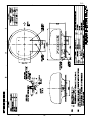
A-7
Y. Hatai
D-1
Y. Hatai
D-2
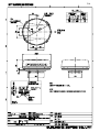
Y. Hatai
D-3
D-4
Y. Hatai
%
$
#
)0&
4&
5&
O
ࠕࠞ 4'&
ࠢࡠ $.-
/,#52(OǾ
ࠪࡠ
ࠕࠝ
ࠠ
㩚㩎㩨㩢
ࠕࠞ
ࠢࡠ
/,#52(OǾ
/,#52(Ǿ
ᄖㇱⵝ⟎
':6 '37+2/'06
/#:O
)&%'640
/,#54/&6/#2
/,#52(
*7$ 5O
ᄖㇱࡉࠩ 12
':6 $7<<'4
㝼⟲ត⍮ᯏ
0/'# 6&*
'%*1 5170&'4
6&%
ࡄ࠰ࠦࡦ
2%
45%
ࡋ࠺ࠖࡦࠣࡦࠨ
*'#&+0) 5'0514 2)
/,#52(OǾ
ࠪࡠ 9*6
ࠢࡠ $.ࠠ ;'.
㩚㩎㩨㩢 )40
#+5 (#
+(#+5
߹ߚߪ 14
O
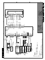
016'
5*+2;#4& 5722.;
126+10
%100'%614 2.7) (+66'& #6 (#%614;
5*+'.& 5*17.& $' '(('%6+8'.; )4170&'& #6 $16* 70+6 '0&5
/,#52(
/,#52(
9*6
$.7
;'.
)40
4'&
$.-
/,#52(
/,#52(
(75'
#
8
#
8 /,#52(
ࠪࡠ 9*6
ࠢࡠ $.
)0& +8US
ᵈ ⸥
㧝㧕ㅧ⦁ᚲᚻ㈩ޕ
㧞㧕ࠝࡊ࡚ࠪࡦޕ
㧟㧕ࠦࡀࠢ࠲ߪᎿ႐ߦߡขઃᷣߺޕ
㧠㧕ࠪ࡞࠼ߪਔ࡙࠾࠶࠻ߢቢోߦធߔࠆߎߣޕ
ㆬᛯ
5'.'%6
ㆬᛯ
5'.'%6
)25ฃାᯏ
)25 4'%'+8'4
)2$$
#&ࠦࡦࡃ࠲
0*2
#&
#* %108'46'4 #% #&
5*+(6* 5*+(6% 5) 8&%
/,#52(%O
&2;%
ᢛᵹེ 8#%
4'%6+(+'4
24
Ǿ*\
,
ᜰ␜ㇱ
&9)0Q
5%#.'
66#-'01
%% %
/#55
MI
,WN4'UWOK
,WP
6;#/#5#-+
)0& +8US
6:A64+)
2.A$
$'#4+0)
*&A/#-'4
0%
0%
0%
0%
0%
,WP
#22418'&
%*'%-'&
&4#90
#
,
6&A&6
45%
4&A&6
4&#
0/'#
4&$
8
':6$7<<
5*+'.&)0&
0'6914,
'A6&A2
'A6&A0
'A4&A2
'A4&A0
0%
5*+'.&
#
,
#**&)*
#%*&)%
%.-*
%.-%
0%
5*+'.&
#
,
6&#
6&$
4&#
4&$
8
)0&
5*+'.&
670+0)A%106
670+0)A+0&
8+&'1
5*+'.&
)0&
#% 5'#
)#+0
2.A#
/1614
#% 4#+0
0%
0%
0%
8
8
8&% &+52.#; 70+6
4&2
)0&
&,
4'(0Q
$40
$.7
22.
)4;
࠴ࡖ
ࠕࠝ
㩛㩡㩅㩁
ࡂࠗ
9*64'&=$?
9*6$.-=$?
$.9*6
4'&
)40
9*6)40=$?
20-
;'.
14)
%8
㩆㩥㨻㩀
ᄥ
㩆㩥㩂㩥
ᄥ
ࠢࡠ
ࠪࡠ
ࠕࠞ
㩚㩎㩨㩢
㩆㩥㩚㩎㩨㩢
ᄥ
ࡕࡕ
ࠠ
࠳ࠗ
㩎㩨㨽㩆㩨㩂
5OǾ
㧔49%%8/#:O
0#/'
ฬ ⒓
6;2'
2
,
8*2
,
8*2
/1&'. %
⦁⥾↪࠳
⋧⚿✢࿑
/#4+0' 4#
+06'4%100'%6+10 &+#)4#/
ⓨਛ✢ㇱ
#06'00# 70+6
45$#
S-1
%
$
#
)0&
4&
5&
O
ࠕࠞ 4'&
ࠢࡠ $.-
/,#52(OǾ
ࠪࡠ
ࠕࠝ
ࠠ
㩚㩎㩨㩢
ࠕࠞ
ࠢࡠ
/,#52(OǾ
/,#52(OǾ
ࠪࡠ 9*6
ࠢࡠ $.ࠠ ;'.
㩚㩎㩨㩢 )40
/,#52(Ǿ
ᄖㇱⵝ⟎
':6 '37+2/'06
/#:O
)&%'640
/,#54/&6/#2
/,#52(
*7$ 5O
ᄖㇱࡉࠩ 12
':6 $7<<'4
㝼⟲ត⍮ᯏ
0/'# 6&*
'%*1 5170&'4
6&%
ࡄ࠰ࠦࡦ
2%
45%
ࡋ࠺ࠖࡦࠣࡦࠨ
*'#&+0) 5'0514 2)
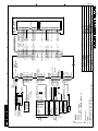
016'
5*+2;#4& 5722.;
126+10
%100'%614 2.7) (+66'& #6 (#%614;
5*+'.& 5*17.& $' '(('%6+8'.; )4170&'& #6 $16* 70+6 '0&5
/,#52(
/,#52(
9*6
$.7
;'.
)40
4'&
$.-
/,#52(
/,#52(
(75'
#
8
#
8 /,#52(
ࠪࡠ 9*6
ࠢࡠ $.
)0& +8US
#+5 (#
+(#+5
߹ߚߪ 14
O
ᵈ ⸥
㧝㧕ㅧ⦁ᚲᚻ㈩
㧞㧕ࠝࡊ࡚ࠪࡦޕ
㧟㧕ࠦࡀࠢ࠲ߪᎿ႐ߦߡขઃᷣߺޕ
㧠㧕ࠪ࡞࠼ߪਔ࡙࠾࠶࠻ߢቢోߦធߔࠆߎߣޕ
ㆬᛯ
5'.'%6
ㆬᛯ
5'.'%6
)25ฃାᯏ
)25 4'%'+8'4
)2$$
#&ࠦࡦࡃ࠲
0*2
#&
#* %108'46'4 #% #&
5*+(6* 5*+(6% 5) 8&%
/,#52(%O
&2;%
ᢛᵹེ 8#%
4'%6+(+'4
24 Ǿ*\
ᜰ␜ㇱ
&9)0Q
5%#.'
)0&
8+&'1
670'A%106
0%
0%
66#-'01
6;#/#5#-+
%% %
/#55
MI
,WN4'UWOK
,WP
)0&
#% 4#+0
)#+0
#% 5'#
670'A+0&
)0& +8US
,WP
#22418'&
%*'%-'&
&4#90
#
,
6&A&6
45%
4&A&6
4&#
0/'#
4&$
8
':6$7<<
5*+'.&)0&
0'6914,
'A6&A2
'A6&A0
'A4&A2
'A4&A0
0%
5*+'.&
#
,
#**&)*
#%*&)%
%.-*
%.-%
0%
5*+'.&
#
,
6&#
6&$
4&#
4&$
8
)0&
5*+'.&
0%
&,
8
8
)0&
8
8
6:A64+)
2. #
2. $
0%
0%
$'#4+0)
/1614
*& 5+)
8&% &+52.#; 70+6
4&2
)0&
,
4'(0Q
㩎㩨㨽㩆㩨㩂
ࠠ
㩛㩡㩅㩁
࠳ࠗ
ࠕࠞ
ࡂࠗ
㩚㩎㩨㩢
ࠪࡠ
㩆㩥㨻㨿
ᄥ
ࠢࡠ
%8
;'.
22.
14)
4'&
)4;
)40
0#/'
ฬ ⒓
6;2'
9*6
9*6$.7=$?
$.-
㩆㩥㩊㩨㨼
ᄥ 9*614)=$?
㩆㩥㩋㨶
ᄥ 9*6$40=$?
㩆㩥㨻㩀
ᄥ 9*64'&=$?
㩆㩥㩚㩎㩨㩢
ᄥ 9*6)40=$?
㩆㩥㩂㩥
ᄥ 9*6$.-=$?
࠴ࡖ
$40
ࡕࡕ
ᄥ
20-=$?
ࠕࠝ
$.7
5OǾ
㧔49%%8/#:O
,
8*2
,
8*2
$ +(
,
0*2
$ /&
ⓨਛ✢ㇱ #06'00# 70+6
45$464
/1&'. %
⦁⥾↪࠳
⋧⚿✢࿑
/#4+0' 4#
+06'4%100'%6+10 &+#)4#/
S-2
S-3
/,#52(%O
&2;%
ᢛᵹེ 8#%
4'%6+(+'4
24
Ǿ*\
(75'
#
8
/,#52(
#
8
ࠪࡠ 9*6
ࠢࡠ $.
8&%
#
)25ฃାᯏ
)25 4'%'+8'4
)2$$
)0& +8US
߹ߚߪ 14
#+5 (#
+(#+5
ㆬᛯ
5'.'%6
$
#&ࠦࡦࡃ࠲
0*2
#&
#* %108'46'4 #% #&
5*+(6* 5*+(6% 5) /,#52(OǾ
ࠪࡠ 9*6
ࠢࡠ $.ࠠ ;'.
㩚㩎㩨㩢 )40
ࡋ࠺ࠖࡦࠣࡦࠨ
*'#&+0) 5'0514 2)
/,#52(OǾ
ࡄ࠰ࠦࡦ
2%
45%
ㆬᛯ
5'.'%6
)0&
4&
5&
/,#52(OǾ
㝼⟲ត⍮ᯏ
0/'# 6&*
'%*1 5170&'4
6&%
ᄖㇱࡉࠩ 12
':6 $7<<'4
ࠕࠞ 4'&
ࠢࡠ $.-
ࠪࡠ
ࠕࠝ
ࠠ
㩚㩎㩨㩢
ࠕࠞ
ࠢࡠ
O
/,#52(Ǿ
ᄖㇱⵝ⟎
':6 '37+2/'06
/#:O
)&%'640
/,#54/&6/#2
/,#52(
*7$ 5O
)0&
ᜰ␜ㇱ
&+52.#; 70+6
4&2
#
,
6&#
6&$
4&#
4&$
8
)0&
5*+'.&
#
,
#**&)*
#%*&)%
%.-*
%.-%
0%
5*+'.&
/,#52(
O
,
/,#52(
#
/,#52(
,
9*6
6&A&6
45%
$.7
4&A&6
;'.
4&#
0/'#
)40
4&$
4'&
8
$. ':6$7<<
5*+'.&)0&
0'6914/,#52(
,
'A6&A2
'A6&A0
'A4&A2
'A4&A0
0%
5*+'.&
)0& +8US
%
&
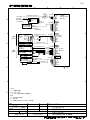
ᵈ ⸥
㧝㧕ㅧ⦁ᚲᚻ㈩ޕ
㧞㧕ࠝࡊ࡚ࠪࡦޕ
㧟㧕ࠦࡀࠢ࠲ߪᎿ႐ߦߡขઃᷣߺޕ
016'
5*+2;#4& 5722.;
126+10
%100'%614 2.7) (+66'& #6 (#%614;
&4#90
,WP
%*'%-'&
,WP
#22418'&
6+6.'
6;#/#5#-+
ฬ⒓
66#-'01
,WN4'UWOK
5%#.'
&9)0Q
/#55
%% &
r㧑
MI
0#/'
4'(0Q
)&%
ࡆ࠺ࠝࡊࡠ࠶࠲
⋧⚿✢࿑
8+&'1 2.166'4
+06'4%100'%6+10 &+#)4#/