1
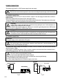
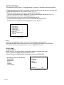
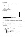
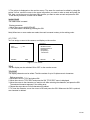
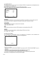
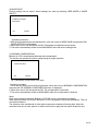
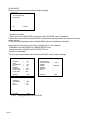
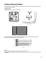
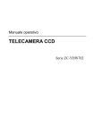
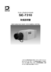
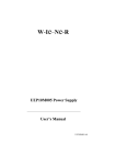
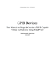
INSTRUCTION MANUAL
CCD CAMERA
CG-301 Series
WARNING – TO PREVENT RISK OF FIRE OR SHOCK, DO NOT EXPOSE THIS CAMERA
TO RAIN OR MOISTURE.
PRECAUTION :
DO NOT REMOVE ANY COVER WHILE THE CAMERA IS OPERATING.
PAL : USE ONLY RECOMMENDED POWER SUPPLY, 24 VAC (20.4 to 27.6 VAC) 50 Hz or
12VDC(10.2 to13.8VDC).
NTSC : USE ONLY RECOMMENDED POWER SUPPLY, 24 VAC (20.4 to 27.6 VAC) 60 Hz or
12VDC(10.2 to13.8VDC).
CAUTION :
LENS MOUNT OF THE CAMERA IS “CS” MOUNT.
CAMERA LENS MOUNT IS SHALLOW, SOME CAMERA LENSES MAY BOTTOM OUT
AND DAMAGE TO THE CCD IMAGER.
DO NOT TOUCH THE CCD GLASS SURFACE.
THE CAMERA MUST BE INSTALLED NEAR A SOCKET-OUTLET WHICH COULD BE
EASILY ACCESSIBLE.
CAUTION
RISK OF ELECTRIC SHOCK
DO NOT OPEN
CAUTION: TO REDUCE THE RISK OF ELECTRIC SHOCK, DO NOT
REMOVE COVER (OR BACK).
NO USER-SERVICEABLE PARTS INSIDE.
REFER SERVICING TO QUALIFIED SERVICE
PERSONNEL.
GRAPHIC SYMBOL EXPLANATION
The lighting flash with an arrow- head symbol within an equilateral
triangle is intended to alert the user to the presence of uninsulated
“dangerous voltage” within the product’s enclosure that may be of
sufficient magnitude to constitute a risk of electric shock to persons.
The exclamation point within an equilateral triangle is intended to
alert the user to the presence of important operating and
maintenance (servicing) instructions in the literature accompanying
the appliance.
En-1
CONTENTS
Section
Page
IMPORTANT SAFEGUARDS
3
INTRODUCTION
5
CAUTIONS FOR OPERATION
5
EXTERNAL CONTROLS AND CONNECTORS
6
LENS
ELECTRONIC CONNECTIONS
MECHANICAL CONNECTION
BACK FOCAL ADJUSTMENT
7
7
7
8
POWER CONNECTION
AC POWER CONNECTION
DC POWER CONNECTION
9
9
9
SETUP MENU
SETTING METHOD
SETTING OPERATION
SETUP ITEMS
MODE SELECT
EXPOSURE SET.
FUNCTION SET.
CAMERA SETUP
LENS ADJUSTMENT
MODE SAVE
BLEMISH COMPENSATION
INITIALIZE
10
12
13
13
14
15
17
21
21
22
22
23
EXTERNAL CONTROL INPUT TERMINAL
CONNECTIONS
SETUP
EXTERNAL UNIT
24
24
25
25
SPECIFICATIONS
26
En-2
IMPORTANT SAFEGUARDS
1. Read Instructions–All the safety and operating instructions should be read before the camera is
operated.
2. Retain Instructions–The safety and operating instructions should be retained for future reference.
3. Heed Warnings–All warnings on the camera and in the operating instructions should be adhered
to.
4. Follow Instructions–All operating and use instructions should be followed.
5. Cleaning–Unplug the power unit from the wall outlet before cleaning. Do not use liquid cleaners
or aerosol cleaners. Use a damp cloth for cleaning.
6. Attachments–Do not use attachments not recommended by your appliance dealer, as they may
cause hazards.
7. Water and Moisture–Do not use the camera in any location in which it may be exposed to water
or moisture.
8. Accessories–Do not place the camera on an unstable cart, stand, tripod, bracket, or table. The
camera may fall, causing serious injury to a child or adult, and serious damage to the camera. Use
only with mounting accessories recommended by your appliance dealer or sold with the camera.
Any mounting of the camera should follow your appliance dealer’s instructions.
9. An appliance and cart combination should be moved
with care. Quick stops, excessive force, and uneven
surfaces may cause the appliance and cart combination
to over turn.
PORTABLE CART WARNING
(Symbol provided by RETAC)
S3125A
10. Ventilation–The camera should never be placed near or over a radiator or heat register.
The camera should not be placed in a built-in installation such as a bookcase or rack unless proper
ventilation is provided or your appliance dealer’s instructions have been adhered to.
11. Power Sources–The camera should be operated only from the type of power source indicated
on the rating plate. If you are not sure of the type of power supply to your installation site, consult
your appliance dealer or local power company. For cameras intended to operate from battery power,
or other sources, refer to the operating instructions.
12. Power-Cord Protection–Power-supply cords should be routed so that they are not likely to be
walked on or pinched by items placed upon or against them, paying particular attention to cords at
plugs, convenience receptacles, and the point where they exit from the camera.
13. Lightning–For added protection for the cam era during a lightning storm, or when it is left
unattended and unused for long periods of time, unplug it from the wall outlet and disconnect the
cable system. This will prevent damage to the camera due to lightning and power-line surges.
En-3
14. Overloading–Do not overload wall outlet and extension cord, as this can result in a risk of fire or
electric shock.
15. Object and Liquid Entry–Never push objects of any kind into the camera through openings, as
they may touch dangerous voltage points or short-out parts that could result in a fire or electric shock.
Never spill liquid of any kind on the camera.
16. Servicing–Do not attempt to service the camera yourself as opening or removing covers may
expose you to dangerous voltage or other hazards. Refer all servicing to qualified service personnel.
17. Damage Requiring Service–Unplug the power unit from the wall outlet. Refer servicing to
qualified service personnel under the following conditions.
a. When the power-supply cord or plug is damaged.
b. If liquid has been spilled, or objects have fallen into the camera.
c. If the camera has been exposed to rain or water.
d. If the camera does not operate normally by following the operating instructions. Adjust only
those controls that are covered by the operating instructions, as an improper adjustment of other
controls may result in damage and will often re-quire extensive work by a qualified technician to
restore the camera to its nor-mal operation.
e. If the camera has been dropped or the cabinet has been damaged.
f. When the camera exhibits a distinct change in performance. This indicates a need for service.
18. Replacement Parts–When replacement parts are required, be sure the service technician has
used replacement parts specified by qualified dealer or that have the same characteristics as the
original part.
Unauthorized substitutions may result in fire, electric shock or other hazards.
19. Safety Check–Upon completion of any service or repairs to the camera, ask the service
technician to perform safety checks to determine that the camera is in proper operating condition.
En-4
INTRODUCTION
Thank you for purchasing this product. This product is a multiple function and a high quality CCD
camera developed considering a high-end security.
The following functions are built-in:
(1) Wide Dynamic Range function
This function makes it possible to capture both high-luminance and low-luminance subjects.
Dynamic Range of max.60 dB.
(2) Day & Night function
This is function to capture high quality color images during the day and clear B&W images at
night.
(3) Electronic Sensitivity Up function
(4) Electronic Zoom function
(5) On Screen Display function
(6) High Quality picture
(7) Small Size
CAUTIONS FOR OPERATION
Do not touch the photoconductive surface of the CCD imager element. Scratches may occur.
If dust sticks on the surface, wipe it off softly with a lens cleaning paper.
Do not use this camera outdoors.
Avoid places where an inflammable gas or a corrosive atmosphere exists.
If the camera case becomes dirty, wipe off with a soft dry cloth. For the large dirt on the case, wipe it
off using a soft cloth moistened a neutral detergent diluted with water and wipe again with the dry
cloth. Never use alcohol, benzine or other volatile solutions.
Don’t image excessive light sources (sunlight etc.) for many hours.
If CCD imager element is exposed to ultraviolet rays for many hours, the filter colour on the surface
of CCD imager element fades. Don't image sunlight or illumination directly, when a camera is left as
it is. Don't image sunlight or illumination directly, even if the power is turned off.
White spots may appear on the screen. However this is not a failure.
En-5
EXTERNAL CONTROLS AND CONNECTORS
3
5
CAMERA MOUNT
ADAPTER
7
4
6
8
9
1
2
10
3
BACK VIEW
TOP/FRONT VIEW
Fig.1
① Lens Mount
The camera has a standard CS lens mount but can use a C-mount lens when a C/CS-mount adapter is installed
between the lens and camera.
② Back Focus Lock Screw
Loosen to adjust the back focus to match the lens attached to the CS mount. Refer to the section on Back Focus
Adjustment in this manual.
③ Camera Mounts
Top or bottom mounting. Maximum thread length is 3/16-inch. Attach the camera mount adapter to extend
thread depth to a standard 1/4-inch.
④ Video Output Connector
This coaxial connector (BNC type) outputs the video signals.
⑤ Lens Connector
Four-pin DC-control connector for auto iris lens. Refer to the section on Lens in this manual for pin connections.
⑥ RS485 Terminating Switch
This is the switch to terminate between signals of RS-485.
ON : Terminated with 100 ohm.
OFF : Not terminated
⑦ LEDs
LEDs light up or blink while using Direct-key function and displaying Camera Setup Menu.
Refer to the section on Setting Operation in this manual.
⑧ Setup Switch
This is the switch to display and operate the menu when OSD function is used. And when Direct-key function is
used, it is used for the selection of ON or OFF. Refer to the section on Setting Operation in this manual.
⑨ Power Input Terminal
Three-pin terminal strip, push-in type; 24 VAC/12 VDC for NTSC/PAL models.
⑩ External Control Input Terminal
This is the I/O terminal of the signal with an electronic characteristic in accordance with RS-485 standard. In
addition, it is the control signal input terminal for DAY&NIGHT function.
En-6
LENS
This camera can accommodate DC voltage drive auto-iris lens. VIDEO signal controlled lens is not available.
ELECTRONIC CONNECTIONS
Table.1 shows wiring scheme for the 4pin Auto iris connector.
Lens Connector
Auto-iris Lens
Table 1
Connector
Pin No.
2
1
4
3
(View from wiring side of plug)
Fig. 2
DC VOLTAGE DRIVE
AUTO-IRIS LENS
1
CONT. ( )
2
CONT. (+)
3
DRIVE (+)
4
DRIVE ( )
MECHANICAL CONNECTION
Before mounting any lens onto this camera, check that the rear lens dimensions do not exceed the following
maximum length, otherwise CCD imager could be damaged.
The camera is shipped, ready to accept “CS“ type lens. If standard “C“-mount lens are to be used, it is necessary
to install the “C-mount Adapter“ ring first, then the lens.
LENS "X"
“X”
CS = 0.2" (6 mm)
C = 0.4" (10 mm)
Fig.3
En-7
BACK FOCAL LENGTH ADJUSTMENT
The camera has been factory-adjusted for the proper back focal length using a standard CS Mount lens.
However, when the lens is mounted, it may be necessary to readjust back focal length to match the lens being
used.
ALLEN WRENCH
10mm
50mm
Approx.15
CAMERA
Fig.4
CAUTION :
If the back focus locking screw is tightened too strong, the thread section of “Lens Mount” may be damaged.
To tighten the back focus locking screw, use a 1.5 mm ALLEN WRENCH.
Hold the short side of the handle (as shown in Fig.4), and turn it clockwise lightly to the stop position. Turn a little
more (approx. 15 degrees) from this position.
For zoom lens:
1. With the camera in operation, view an object at least 70 feet (25 m) away.
2. Make sure the lens iris is wide open.
3. Set LENS FOCUS to FAR position.
4. Adjust lens ZOOM to WIDE angle. (Wide field of view)
5. Loosen the back focus lock screw at the side of the camera using a 1.5 mm ALLEN WRENCH.
Turn the lens mount to obtain the sharpest image on the monitor.
Then tighten the back focus locking screw clockwise. (See Fig.1 for location.)
6. Move lens ZOOM to TELEPHOTO. (Smallest field of view)
7. Adjust LENS FOCUS (by the controller) for best picture.
LENS ADJUSTMENT
Before using a DC voltage drive auto-iris lens, do the LENS ADJUSTMENT.
Refer to the section on Setup Items on this manual in details.
En-8
POWER CONNECTION
This camera uses 24VAC or 12VDC power supply for the main supply.
CAUTION :
Take care not to short-circuit the power line wire, when connecting the power-supply cord to the camera.
AC POWER CONNECTION
A main supply of 24VAC (20.4 to 27.6 VAC) 50 / 60Hz is required. This main supply must also have a minimum
rating of 270mA.
Remove the sheath at the end of power cord in the length of 10mm.
Twist and straighten the wires, then insert the wires to three holes of the terminal. If the insertion can not be made
smoothly, try it again while pushing respective button above the hole.
CAUTION :
Confirm that the cord is connected to the terminal securely by pulling the cord. Confirm that there is no
whisker of wires outside the holes of terminal.
Connect to 24VAC class 2 power supply only. Make sure to connect the grounding lead to the GND terminal
when the power is supplied from a 24VAC power source.
CAUTION :
When two or more cameras are used by one transformer, use a transformer having the rated current
more than the current consumed with the number of cameras ×24VAC 270 mA.
DC POWER CONNECTION
CAUTION :
DC power supply must be marked with a CE symbol.
CAUTION :
If the power-supply cord is short-circuited, excessive current flows and is extremely dangerous. The
line fuse must be required. (see Fig.6).
The rated power supply voltage of this camera is +12VDC (+10.2 to +13.8VDC). Be sure to use the camera
within this range of voltage.
Power supply connections are shown in Fig.6. If a fuse is required, use a slow blow fuse connected to the +
terminal of the power supply within 10cm (4inch) of the terminal.
CAUTION :
Be sure to wire the power plug polarity correctly.
Current consumption 390mA per camera is required.
When selecting and connecting the power-supply cord, take care concerning the following:
① Current allowance of the power-supply cord.
② Power supply voltage drop due to excessive length or size of wire.
TRANSFORMER
INPUT
REAR PANEL
Button
OUTPUT
DC POWER
SUPPLY
REAR PANEL
FUSE (slow blow)
1.0 A
Button
+12 V
GND
DC 12 V
AC 24 V
Fig.5
En-9
10cm (4.0 inch) MAX
Fig.6
SETUP MENU
This product built in OSD function and can customize the camera setting.
The menu list is shown in the following.
MODE SELECT
STANDARD
DAY&NIGHT
WIDE
CASINO
USER MODE
RETURN
END
MAIN MENU
EXPOSURE SET.
MODE SELECT
EXPOSURE SET.
FUNCTION SET.
CAMERA SETUP
LENS ADJUSTMENT
MODE SAVE
BLEMISH COMPENSATION
INITIALIZE
AE MODE
LEVEL
FLICKERLESS
AGC
SENS UP
DAY&NIGHT
DETECT TIME
FILTER LIMIT
END
→ WD
→0
→ OFF
→ ON
→4
→ AUTO
→ 5 sec
→ 10min
RETURN
END
LENS ADJUSTMENT
OK
CANCEL
MODE SAVE
CURRENT SETTINGS
ARE SAVED
OK
CANCEL
FUNCTION SET.
SYNC SELECT
WHITE BALANCE
CHROMA
GAMMA
E-ZOOM
MASKING
TITLE
RETURN
→
→ AUTO
→
→ NORMAL
→
→
→
END
NEXT PAGE
BLEMISH COMPENSATION
COVER THE LENS
OK
CANCEL
CAMERA SETUP
ADDRESS
COM SPEED
LED
SWITCH
RETURN
→ 1
→ 4800
→ ON
→ ON
END
INITIALIZE
ALL SETTINGS ARE
INITIALIZED
OK
CANCEL
En-10
SYNC SELECT
PHASE SHIFT
SYNC MODE
PHASE
AUTO
→
RETURN
Phase Value = 28
END
*Only when AUTO is selected
CHROMA
RY GAIN
BY GAIN
RY HUE
BY HUE
RETURN
→
→
→
→
-1
-2
1
1
END
E-ZOOM
ZOOM
POSITION
RETURN
POSITION
→ OFF
END
*Only when the zoom magnification is selected
MASKING
MASK SETTING
MASK
→ OFF
MASK EDIT
MASK ERASE
RETURN
END
*Only when ON is selected for MASK
TITLE EDIT
TITLE
TITLE
TITLE EDIT
RETURN
→ OFF
END
ABCDEFGHIJKLM
NOPQRSTUVWXYZ
abcdefghijklm
nopqrstuvwxyz
0123456789-/
RETURN
BS
*Only when ON is selected for TITLE
En-11
SETTING METHOD
This camera has multiple functions, and can be adapted to a shooting place.
There are 2 methods which are specified functions of the camera.
(1) Setting method by using OSD(On-screen Display) function. Refer to the next section in details.
(2) Setting method by using Direct-key function.
This camera has Direct-key function. This function can control the following functions directly without
displaying the menu. When ON is selected for each function, LED on the rear panel light up and is
displayed to be operating.(Fig.7-1, 7-3)
Functions which can be changed directly are as follows.
① AGC : ON / OFF
② DAY&NIGHT : ON(AUTO mode)/OFF(COLOR mode)
When ON is selected, AGC is automatically turned ON.
③ SENS : ON / OFF
When the number of stored fields is selected on the menu, it is usually maintained. But the
selected number is lost if OFF is set by Direct-key function.
④ WD: ON(WD) / OFF(NORMAL)
The SW which is described to the following sentence shows Fig.1 ⑧.
Press and hold down,
the SETUP MENU is
displayed.
AGC
SELECT
RIGHT
LEFT
WD
D/N
UP
DOWN
SENS
Fig.7-1 Normal SW setting (menu non-display)
Fig.7-2 SETUP MENU SW Setting
AGC
D/N
WD
SENS
Fig.7-3 Normal LED status
blink
点滅
Fig.7-4 SETUP MENU LED status
En-12
SETTING OPERATION
This camera has OSD function. To change settings on the menu, operate the following procedure.
1. Press and hold down the SW for 2 seconds or more. The SW on the rear panel is used. (Fig.1 ⑧)
2. MAIN MENU appears on the monitor as shown in Fig.7-5.
3. Move the cursor to an item you want to change by using the SW.
The menu of the selected item is displayed. The SW can be used as direction key. (Fig.7-2)
4. Select a parameter you want to change and specify it.
5. To close the menu, move the cursor to END and press the SW.
To return the previous page, move the cursor to RETURN and press the SW.
All LED on the rear panel blink while displaying the menu. (Fig.7-4)
MAIN MENU
→
MODE SELECT
→
EXPOSURE SET.
→
FUNCTION SET.
→
CAMERA SETUP
LENS ADJUSTMENT
MODE SAVE
BLEMISH COMPENSATION
INITIALIZE
END
Fig.7-5 MAIN MENU
Note)
If you don’t operate the menu for 1 minute, the menu disappears automatically.
When selecting RETURN or END on the menu, current settings are stored in the EEPROM.
As for items limited by setting the function, * mark is displayed in the item.
SETUP ITEMS
(1) MODE SELECT
MODE SELCET can set parameters to the preset setting by selecting each mode.
It is also possible to register the setting edited by a user.
Refer to the section of MODE SAVE for setting procedure of USER MODE.
The following modes can be selected.
STANDARD
DAY&NIGHT
WIDE
CASINO
USER MODE
MODE SELECT
STANDARD
DAY&NIGHT
WIDE
CASINO
USER MODE
RETURN
END
Fig. 7-6 MODE SELCET menu
En-13
Parameters of each mode is shown in Fig.7-7,7-8,7-9,7-10.
STANDARD
FUNCTION SET.
EXPOSURE SET.
AE MODE
LEVEL
FLICKERLESS
AGC
SENS UP
DAY&NIGHT
DETECT TIME
FILTER LIMIT
RETURN
→ NORMAL
→
0
→
OFF
→
ON
→
4
→ COLOR
→ 5sec
→ OFF
SYNC SELECT
WHITE BALANCE
CROMA
GAMMA
E-ZOOM
MASKING
TITLE
→ AUTO
→ AUTO
→
→ NORMAL
→
→
→
RETURN
END
END
Fig. 7-7 Setting parameters of STANDARD
DAY&NIGHT
FUNCTION SET.
EXPOSURE SET.
AE MODE
LEVEL
FLICKERLESS
AGC
SENS UP
DAY&NIGHT
DETECT TIME
FILTER LIMIT
RETURN
→ NORMAL
→
0
→
OFF
→
ON
→
OFF
→ AUTO
→ 5sec
→ 10min
SYNC SELECT
WHITE BALANCE
CROMA
GAMMA
E-ZOOM
MASKING
TITLE
→ AUTO
→ AUTO
→
→ NORMAL
→
→
→
RETURN
END
END
Fig.7-8 Setting parameters of DAY&NIGHT
WIDE
FUNCTION SET.
EXPOSURE SET.
AE MODE
LEVEL
FLICKERLESS
AGC
SENS UP
DAY&NIGHT
DETECT TIME
FILTER LIMIT
RETURN
→
WD
→
0
→
OFF
→
ON
→
4
→ COLOR
→ 5sec
→ OFF
END
SYNC SELECT
WHITE BALANCE
CROMA
*GAMMA
*E-ZOOM
MASKING
TITLE
→ AUTO
→ AUTO
→
→
→
→
→
RETURN
END
Fig.7-9 Setting parameters of WIDE
CASINO
FUNCTION SET.
EXPOSURE SET.
AE MODE
LEVEL
FLICKERLESS
AGC
SENS UP
DAY&NIGHT
DETECT TIME
FILTER LIMIT
RETURN
→ NORMAL
→
0
→
OFF
→
ON
→
4
→ COLOR
→ 5sec
→ OFF
END
SYNC SELECT
WHITE BALANCE
CROMA
GAMMA
E-ZOOM
MASKING
TITLE
→ INT
→ INDOOR
→
→ SCENE1
→
→
→
RETURN
END
Fig. 7-10 Setting parameters of CASINO
En-14
(2) EXPOSURE SET.
In this menu, the exposure system of the camera can be specified.
There are 2 kinds of EXPOSURE SET. menu.
A. AE MODE other than MANUAL
EXPOSURE SET.
AE MODE
LEVEL
FLICKERLESS
AGC
SENS UP
DAY&NIGHT
DETECT TIME
FILTER LIMIT
RETURN
B. MANUAL is selected for AE MODE
EXPOSURE SET.
→
→
→
→
→
→
→
→
WD
0
OFF
ON
4
AUTO
5 sec
10min
END
AE MODE
LEVEL
SHUTTER SPEED
AGC
SENS UP
DAY&NIGHT
DETECT TIME
FILTER LIMIT
RETURN
→ MANUAL
→ 0
→ 1/60
→ ON
→ OFF
→ AUTO
→ 5 sec
→ 10min
END
Fig. 8-1 EXPOSURE SET. menu
AE MODE
AE operation mode can be selected.
WD → NORMAL → BLC → MANUAL The mode turns in this order.
WD : Wide Dynamic Range function operates.
This function is used under shooting conditions in which there is a mixture of high-luminance and
low –luminance subjects. When this mode is selected, E-ZOOM is not available.
NORMAL : This mode is AE operation which is controlled by the electronic shutter and mechanical
iris.
BLC : This mode offers a Back Light Compensation function.
This mode allows fine picture correction to prevent the subject from being extremely dark due to
strong backlight.
MANUAL : The electronic shutter speed can be selected. Refer to SHUTTER SPEED.
LEVEL
The video output level can be adjusted. (Adjustable range : -5 ~ 5)
Note) When BLC is selected for AE MODE, the level can’t be adjusted.
FLICKERLESS
When AE MODE other than MANUAL is selected, this item appears on the menu.
When ON is selected, the shutter speed is fixed at 1/100s (NTSC) or 1/120s (PAL).
SHUTTER SPEED
When MANUAL is selected for AE MODE, this item appears on the menu.
1/60(NTSC), 1/50(PAL), 1/100(NTSC), 1/120(PAL), 1/250, 1/500, 1/1000, 1/2000, 1/4000,
1/10000, 1/20000, 1/50000
AGC
AGC automatically controls the gain in low-brightness zones.
This function can be switched ON or OFF.
SENS UP
This function offers optimal brightness level by increasing the number of stored fields.
Refer to the following value.
OFF, 2, 4, 6, 8, 10, 20, 40
Note) When MANUAL is selected for AE MODE, OFF is automatically selected for SNES UP.
While SENS UP is selected, noise spots, blemish of CCD or a whitish phenomenon may
appear in the picture. This is a normal phenomenon.
En-15
DAY & NIGHT
This item specifies the switch between Color and BW picture.
AUTO : Auto mode enables the camera to switch between Color and BW picture in response to
light condition.
COLOR : Fixes to Color picture.
BW : Fixes to BW picture.
EXT. : This mode allows the camera to control by the external signal. Refer to the section on
EXTERNAL CONTROL INPUT TERMINAL in this manual.
Note)
When OFF is selected for AGC, AUTO mode is not available.
If you switch OFF for AGC while selecting AUTO, COLOR is selected for DAY&NIGHT compulsorily.
When AUTO is selected, it is a possibility not to be shifted the filter under the angle of view or
illumination conditions.
This camera provides a function to stop the filter when the hunting occurs, to prevent this problem.
Specify the stop time of the filter in FILTER LIMIT item.
To do a more certain method, we recommend EXT mode which switch between Color and BW
picture by the external input.
DETECT TIME (This item is used when AUTO or EXT is selected for DAY&NIGHT.)
The detect time of DAY&NIGHT function can be selected. The filter shifts when the change of the
brightness level is kept more than the selected time in this item.
5sec, 30sec
FILTER LIMIT (This item is used when AUTO or EXT is selected for DAY&NIGHT.)
When the hunting occurred while DAY&NIGHT function is active, the stop time of the filter can be set
in the following value.
OFF, 10min, 30min
Note) *mark is displayed while this function operates, and the filter has been stopped.
En-16
(3) FUNCTION SET.
In this menu, functions other than exposure system can be specified.
EXPOSURE SET.
SYNC SELECT
WHITE BALANCE
CROMA
GAMMA
E-ZOOM
MASKING
TITLE
→
→ AUTO
→
→ NORMAL
→
→
→
RETURN
END
Fig.9-1 FUNCTION SET. menu
(3-1)SYNC SELECT
This camera supports the synchronization mode such as line lock and internal.
PHASE SHIFT
SYNC SELECT
SYNC MODE → AUTO
PHASE
→
Phase Value = 27
RETURN
END
Fig.9-2 SYNC SELECT menu
SYNC MODE
The synchronization mode can be selected.
AUTO : At AC power supply, this mode allows the camera to use the phase of the AC power as the
reference. The camera operates in Line Lock mode.
At DC power supply, an inside crystal oscillator is used as INT.Sync Generator.
INT : In this mode, the camera always use an inside crystal oscillator as INT. Sync Generator.
PHASE
The vertical phase can be shifted in Line Lock mode.
Adjusting procedure
1. Move the cursor to SYNC MODE and select AUTO.
2. Move the cursor to PHASE and press SW. PHASE SHIFT menu is displayed.
3. On PHASE SHIFT menu, the vertical phase can be adjusted by turning on the SW up or down.
Refer to Fig.9-3.
Note) The phase of each camera is set to same phase at the factory. Usually, the phase doesn’t
need readjustments.
0° +90°
-180°
+180°
-90°
VSYNC
PAL :2.5H
NTSC:3H
En-17
DOWN Ù UP
Fig.9-3 PHASE SHIFT
Adjustable range
0 ~ 52 (NTSC)
0 ~ 62 (PAL)
(3-2) WHITE BALANCE
WHITE BALANCE
You can select one of 4 modes for white balance adjustment as follows.
AUTO, HOLD, INDOOR (Approx. 2800K), OUTDOOR (Approx. 6000K)
AUTO : The white balance is adjusted automatically to provide the optimum picture.
HOLD : In this mode, the WB gain just before changing to this mode is kept.
INDOOR, OUTDOOR : These modes are the fixed WB gain.
Setting procedure for HOLD
1. Image a subject. Move the cursor to WHITE BALANCE and select AUTO.
2. Change WHITE BALANCE from AUTO to HOLD.
With this procedure, WB gain is kept.
Note) If white balance mode is changed from HOLD to other modes, the stored gain is lost.
(3-3) CHROMA
The chroma gain and hue level can be adjusted.
CHROMA
RY GAIN
BY GAIN
RY HUE
BY HUE
RETURN
→
→
→
→
-1
-2
1
1
END
Fig.9-4 CHROMA menu
RY GAIN
The chroma gain level can be adjusted. Adjustable range -5 ~ 5
BY GAIN
The chroma gain level can be adjusted. Adjustable range -5 ~ 5
RY HUE
The chroma hue level can be adjusted. Adjustable range -5 ~ 5
BY HUE
The chroma hue level can be adjusted. Adjustable range -5 ~ 5
(3-4) GAMMA
GAMMA
Gamma curve can be selected.
NORMAL(Approx. 0.6), SCENE1(Approx. 0.45), SCENE2(Approx. 1.0)
Note) It isn’t possible to select Gamma curve, when WD is selected for AE MODE.
En-18
(3-5) E-ZOOM
This camera built in electronic zoom, electronic panning and electronic tilting function.
In this menu, these functions is specified.
E-ZOOM
ZOOM
POSITION
RETURN
POSITION
→ 2.0
→
END
Fig.9-5 E-ZOOM menu
ZOOM
The zoom magnification is selected from the following.
OFF, 1.5, 2.0, 2.5
Note) When 1.5, 2.0 or 2.5 is selected, WD and MASKING function is not available.
POSITION
When the zoom magnification is selected for ZOOM, the position of the image can be adjusted.
Adjusting procedure
1. Move the cursor to ZOOM and select 1.5, 2.0 or 2.5.
2. Move the cursor to POSITION and press the SW. POSITION menu is displayed.
3. The frame position can be adjusted by turning on the SW up, down, left or right on this menu.
Note) Electronic tiltting function is limited by ZOOM. Only when the zoom magnification is 1.5, a full
tilting operation is possible.
(3-6) MASKING
This camera contains MASK function.
MASKING
MASK
MASK EDIT
MASK ERASE
RETURN
MASK SETTING
→ OFF
→
END
Fig.9-6 MASKING menu
MASK
The mask display can be switched ON or OFF on the monitor screen.
MASK EDIT
The area of a mask can be edited. It is possible to make up to 8.
Editing procedure
1. Move the cursor to MASK and select ON.
2. Move the cursor to MASK EDIT and press the SW. MASK SETTING menu is displayed.
En-19
3. The pointer is displayed on the monitor screen. The area of a mask can be edited by using this
pointer. At first, move the cursor to the upper left position you want to make a mask and press the
SW. Next, move the cursor to the lower right position you want to make a mask and press the SW.
In the above procedure, a mask can be made.
MASK ERASE
The made mask is erased.
Erasing procedure
1. Move the cursor to MASK ERASE.
2. The made mask is erased by pressing the SW.
Note) When two or more masks are made, the mask is erased contrary to the making order.
(3-7) TITLE
You can assign a name to the camera, and display on the monitor.
TITLE
TITLE
TITLE EDIT
RETURN
TITLE EDIT
→ ON
→
ABCDEFGHIJKLM
NOPQRSTUVWXYZ
abcdefghijklm
nopqrstuvwxyz
0123456789-/
END
RETURN
BS
Fig.9-7 TITLE menu
TITLE
The title display can be switched ON or OFF on the monitor screen.
TITLE EDIT
The display character can be edited. The title consists of up to 16 alphanumeric characters.
Editing procedure
1. Move the cursor to TITLE and select ON.
2. Move the cursor to TITLE EDIT and press the SW. TITLE EDIT menu is displayed.
3. Move the cursor to the character you want to edit. After selecting the character, and press the SW.
The selected character appears in the editing area.
4. Repeat the steps above until all characters are edited.
5. To clear the character, move the cursor to BS and press the SW. Whenever the SW is pushed,
one character is deleted.
En-20
(4) CAMERA SETUP
This camera has an external control input interface (RS-485). All parameters and adjustments can
be changed from an external unit.
Refer to the section on External Control Input Terminal in details.
In this menu, setting of the communication, LED and Switch can be selected.
CAMERA SETUP
→ 1
→ 4800
→ ON
→ ON
ADDRESS
COM SPEED
LED
SWITCH
RETURN
END
Fig.10 CAMERA SETUP menu
ADDRESS
The number to identify two or more cameras is specified. It is possible to communicate up to 30.
Note) When the number is repeated in the system, cameras don’t operate correctly.
COM SPEED
The communication rate with an external unit is selected.
2400, 4800, 9600, 19200
LED
When Direct-key function is active, LED illumination can be switched ON or OFF.
SWITCH
This item can be selected enable or disable setting of Direct-key function.
ON : enable, OFF : disable
(5) LENS ADJUSTMENT
The mechanical iris adjustments involve fine adjustments of variations in the mechanical iris
reference voltage. Before using this camera, do this adjustment.
LENS ADJUSTMENT
OK
CANCEL
Fig.11 LENS ADJUSTMENT menu
Operation procedure
1. Move the cursor to LENS ADJUSTMENT and press the SW. LENS ADJUSTMENT menu is
displayed.
2. Move the cursor to OK and press the SW. The adjustment is executed.
At this time, make adjustment with a bright and flickerless scene.
3. The screen automatically reverts to MAIN MENU when the adjustment process ends.
Note) When you change the lens, do this procedure again.
En-21
(6) MODE SAVE
Current settings can be saved. Saved settings can read by selecting USER MODE of MODE
SELECT.
MODE SAVE
CURRENT SETTINGS
ARE SAVED.
OK
CANCEL
Fig.12 MODE SAVE menu
Operation procedure
1. After changing parameters and adjustments, move the cursor to MODE SAVE and press the SW.
MODE SAVE menu is displayed.
2. Move the cursor to OK and press the SW. Parameters and adjustments are saved.
3. The screen automatically reverts to the MAIN MENU when the save of setting ends.
(7) BLEMISH COMPENSATION
Blemish of CCD is automatically detected and compensated.
This function can protect the picture quality though a simple operation.
BLEMISH COMPENSATION
COVER THE LENS
OK
CANCEL
Fig.13 BLEMISH COMPENSATION menu
Operation procedure
1. Cover the lens during use so that no light enters. Move the cursor to BLEMISH COMPENSATION
and press the SW. BLEMISH COMPENSATION menu is displayed.
2. Move the cursor to OK and press the SW. The compensation is executed.
3. The screen automatically reverts to MAIN MENU when the compensation is finished.
Note)
Even if this function is executed, Blemish of CCD will not be compensated completely.
While selecting SENS UP function, Blemish of CCD may appear in the picture permanent. This is a
normal phenomenon.
The structure of the mechanical iris lens aperture prevents complete of blocking light. When the
mechanical iris lens is used, perform in dark environment or apply the lens cap to shade the lens.
En-22
(8) INITIALIZE
Present settings are reset to the factory default settings.
INITIALIZE
ALL SETTINGS ARE
IINITIALIZED
OKFig.
CANCEL MENU
8 INITIALIZE
Fig.14 INITIALIZE menu
Operation procedure
1. Move the cursor to INITIALIZE and press the SW. INITIALIZE menu is displayed.
2. Move the cursor to OK and press the SW. All parameters and adjustments are reset to the factory
default settings.
3. The screen automatically reverts to MAIN MENU when the initialization is finished.
Note) Even if this function is executed, the following item is not initialized.
ADDRESS and COM SPEED on CAMERA SETUP menu
Adjustment value of PHASE on SYNC SELECT menu
Blemish Compensation
The fig.14 shows parameters after executing INITILIZE. (factory default settings)
FUNCTION SET.
EXPOSURE SET.
AE MODE
LEVEL
FLICKERLESS
AGC
SENS UP
DAY&NIGHT
DETECT TIME
FILTER LIMIT
RETURN
→
WD
→
0
→
OFF
→
ON
→
4
→ AUTO
→ 5sec
→ 10min
END
SYNC SELECT
WHITE BALANCE
CROMA
*GAMMA
*E-ZOOM
MASKING
TITLE
RETURN
CAMERA SETUP
ADDRESS
COM SPEED
LED
SWITCH
RETURN
→ 1
→ 4800
→ ON
→ ON
END
Fig.15 Setting parameters of INITIALIZE
En-23
→
→ AUTO
→
→ NORMAL
→
→
→
END
EXTERNAL CONTROL INPUT TERMINAL
This camera has an external control input terminal and can be operated remotely by supplying a
control signal to this terminal.
CONNECTIONS
Connections of control signals are as follows.
Pin1
Pin7
Magnified Figure
Fig.16
Pin No.
1
2
3
4
5
6
Description
A (+)
B (-)
GND
A (+)
B (-)
GND
7
D&N Control Signal Input
If you operate cameras remotely by using this terminal, connect the following enclosed cable.
We recommend to extend it with a twisted pair cable.
Brown
Black
White
Red
Black
White
Red
Pin7
Pin1
Fig.17
Note)
Turn off the power supply of the camera and connect the cable.
Use the extension cable which has the same characteristic impedance as the terminating resistance.
(100ohms)
En-24
SETUP
To make up the camera system with RS-485, do the following procedure.
Setting procedure
1. Connect the cable for each camera.
2. Terminate the camera installed in the end of the system. Turn off the termination of other
cameras.
Refer to Fig.1 ⑥
3. Set the address number for each camera on CAMERA SETUP menu.
Notice so that the number is not repeated.
4. Set the communication rate on CAMERA SETUP menu. Select the same rate for each camera.
To control DAY&NIGHT function remotely, do the following procedure.
Setting procedure
1. Select EXT. for DAY&NIGHT function on FUNCTION SET. menu.
2. The mode of DAY&NIGHT function can be switch to supply the control signal.
Open or High Input : Operates AUTO mode
Short or Low input : Operates BW mode
(This line is pulled up in the camera. The power of this line is not enough to drive an external unit.)
Rating and electronic characteristics
Input Voltage VIN : -0.3 ~ 3.3V
Input Voltage High VIH : Min.3.0V
Input Voltage Low VIL : Max.0.3V
Notice so that the above value is not exceeded.
EXTERNAL UNIT
This product built in RS-485 interface, and can be controlled with an external unit.
For example, this camera can be operated remotely by using a PC installed in the following
application.
CG-301 Controller
This application is included in the enclosed CD.
Refer to the enclosed CD in details.
En-25
SPECIFICATIONS
Model Name
CG-301
TV System
NTSC
PAL
Power
AC24V(±15%) / DC12V(±15%)
Power Consumption
270mA(24VAC) / 390mA(12VDC)
Imager
1/3” Image Format vertical double density Interline transfer CCD
Picture Elements (active)
Approx. 380K pixels
Approx. 440K pixels
Synchronization
Internal / LineLock
Signal to Noise Ratio
48dB(AGC off, weighting)
Video Output
1.0Vp-p/ Composite (75ohms)
480TV Lines (Color)
530TVLines(BW)
1.0Lux(Color) 0.1Lux (BW)
0.025Lux(SENSup x40 Color)
(at F1.2 50IRE)
Max, 60dB (WideD-AE mode)
Horizontal Resolution
Minimum Scene Illumination
D range
Function
Wide Dynamic Range Function
Electronic Sensitivity Up Function
DAY&NIGHT Function
E-zoom Function (Normal-AE mode)
OSD Function
BLC Function
Lens Mount
Auto White Balance
WCCB Function
AGC Function
SYNC Selectable (Internal / Auto)
Flickerless Function
CS Mount (Flange Back Adjustable)
Usable Auto Iris Lens
DC Voltage Drive Auto-Iris Lens
Camera Mount
1/4”-20, top or bottom
Weight (Excluding Lens)
0.2kg
Dimensions (Less Lens)
53(W)×55(H)×56(D)
Operating Temperature
Connectors
Controls
Accessories (Supplied)
(1)
(2)
(3)
(4)
-10 to +50degrees (0 to +40degrees;Performance Guaranteed)
Video Signal Output (BNC, 75 Ohm)
Auto Iris Lens Output (4pin)
Power Input (3pin)
External control Input (7pin)
Setup Switch
RS485 Terminating SW
4Pin Plug (Small) Type
ALLEN WRENCH
CAMERA MOUNT ADAPTER
CD-ROM
WIRE WITH CONNECTOR
INSTRUCTION MANUAL
1pc
1pc
1pc
1pc
1pc
1pc
Design and specifications are subject to change without notice.
En-26
FUJITSU GENERAL LIMITED
1116, Suenaga,
Takatsu-ku,
Kawasaki 213-8502,
Japan