1
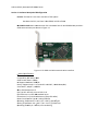
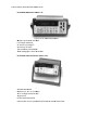
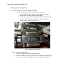
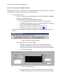
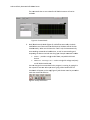
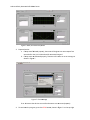
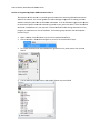
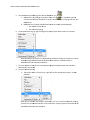
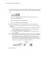
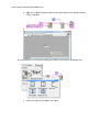
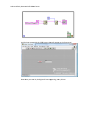
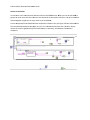
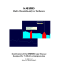
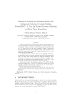
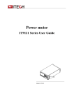
FLORIDAGULFCOASTUNIVERSITY GPIBDevices UserManualonUsage&CreationofGPIBCapable VirtualInstrumentsUsingNILabView Olexiy Kovtunenko, Robert Porter 4/22/2009 Authors: Olexiy Kovtunenko & Robert Porter Section 0: Introduction About: This manual will describe how to use GPIB devices as well as provide instructions on how to construct simple GPIB communication virtual instrument using NI LabView. Purpose: The purpose of this manual is to instruct the user, on how to use GBIP Multi Device Virtual Instrument created for Data Acquisition & Control Systems course that was taught by Dr. Zalewski in spring 2009 semester. As well as instruct user on how to connect GPIB devices to the host PC and to each other. In addition, this manual will describe how to develop a simple Virtual Instrument that is able to communicate with GPIB device and display the output. Authors: O Olexiy Kovtun nenko & Robe ert Porter Section 1: Hardware D Description & & Configuratio on Host PC: The h host PC is the main controlller of the sysstem Hardw ware: Dell PC, Intel Core 2 D Duo E8500, 33.25 Gb of RAM NI GPIB PCI Ca N ard: Main com mmunication link in betweeen host PC an nd GPIB devicces provides 1 GPIB communication port sshown in Figu ure 1.1 Figure 1.1 PCI GPIB card withh communicattion interfacee Detailed Specifications: Compatibility IIEEE 488.1, 48 88.2 GPIB Transfer Rate 1.5 MB//s OS Support Wi O indows® 2000 0/XP Liibrary Supporrt Visual C++® ®, Borland C++ + Builder®, LaabWindows/C CVI, Visual Basic®, Delphi®, LabV VIEW Max. GPIB Con M nnections 15 Bus Type PCI‐1 1671UP: Universal PCI V2.2 2 I//O Connectors 1 x IEEE 488 8 standard 24 4‐pin Dimensions (L x H) 119.91 xx 64.41mm (LLow profile M D1) Po ower Consum mption Typicaal: 5 VDC @ 37 75 mA Operating Tem O mperature 0 ~ ~ 60° C (32 ~ 1 158° F) @ 0‐990% RH Sttoring Tempe erature ‐40 ~ 100° C (‐40 ~ 212° F) @ 5‐ 90% RH Operating Hum O midity 0 ~ 90% % RH, non‐condensing Authors: O Olexiy Kovtun nenko & Robe ert Porter HP 34401A Mu ultimeter (Figgure 1.2): Figure 1.2 HP 34 4401A Multim meter Measure up to M o 1000 volts w with 6 1/2 digits ressolution dc accuracy off 0.0015% acc accuracy of 0.06% 3Hz to 300kHzz ac bandwidtth 10 000 readings//sec. direct to o HP‐IBM HP 53131A Un niversal Counter (Figure 1..3): Figure 1.3 HP 53 3131A Univerrsal Counter 22 25 MHz band dwidth (o optional 1.5, 3 3, 5, or 12.4 G GHz) 10 0‐ or 12‐digit resolution w with 1ss gate time HP‐IB interface e standard Data transfer rrate of up to 2 200 fully form matted measuurements/secc Authors: O Olexiy Kovtun nenko & Robe ert Porter Co onfiguring & Connecting D Devices: 1. Connect GPIB devices to the GPIB caapable worksttation: a. Usse IEEE standaard approved d GPIB cables to connect th he devices: i. Connecct male part o of the cable too the GPIB caapable worksttation ii. Connecct other side o of the cable tto the GPIB deevice iii. Connecct new cable iin the femalee GPIB connecction on the ffirst device iv. Connecct remaining e end to the seecond GPIB deevice see Figu ure 1 v. Secure all screws on n the connecttion ends Figure 1 1. GPIB Chainn Connection 2. Power up devices and w workstation: onnect the po ower cables tto enabled poower outlets a. Co b. Po ower on the d devices by pusshing respecttive button on n each devicee separately c. Po ower up the w workstation and login withh provided useername and p password Authors: O Olexiy Kovtun nenko & Robe ert Porter Section 2: User Manua al for GPIB du ual instrumen nt The objecctive of this se ection is to sh how the user how to read data in LabViiew from the device conneected via GPIB interface. The e procedure iss explained in n the followinng steps. 1. Locate and d open the VI: a. Lo ocate VI in C:\\Documents aand Settings\A Administrator\Desktop\GPIB\userMod de.vi or Locate VI in C:\Documentts and Se ettings\Admin nistrator\Deskktop\GPIB\addvancedModee.vi i. The use er operating rregime providdes basic funcctionality of tthe device ii. In advaanced operatiing regime usser is able to ssent detailed command to o the device, through the provided com mmand field ds for HP 344401A can be fo ound here [1]] iii. Advancced command iv. Advancced command ds for HP 531 31A can be fo ound here [3]] 2. Start the V VI by clicking aappropriate b button on thee top of the LaabView windo ow as shown in figure 2 Figure 2. Initiation of Virtual Instrument he VI can operrate in three different moddes a. Th i. Multim meter Mode (FFigure 3): onlyy communicaation with HP 34401A multim meter is establlished, comm munication is iinitialized witth strictly thiss device. The function ns that are noot included into the native interface of tthis device will not be avvailable Figure 3. Multim meter mode ii. Counte er Mode (Figu ure 4): similarr to multimeteer mode, the counter mod de will esttablish communication excclusively with HP 53131A u universal counter. Authors: O Olexiy Kovtun nenko & Robe ert Porter The com mmands thatt are not nativve for HP 531131A counter will not be availab ble Figure 4. Counte er Mode iii. Both (SSimultaneous) Mode (Figurre 6): unlike ffirst two mod des, the Both mode aallows user to o communicatte with both HP 34401A and HP 53131A simultaaneously. When user clickss on the “Both” tab, the VII automatically starts ssending comm mands to bothh devices, as well as startss reading and outputtting the datum received oonto the graph h. Sample com mmands inclu ude: READ? – prrovides a singgle read of datta, compatible with both devices DC? – makes a single DC voltage read, o only MEASure:VOLTage:D on HP 34401A multimeteer n change the command w hile the program is runnin ng, by typing iit in You can the respective text b box. When yoou start typing a little buttton with the mark will appe ear on the topp (Figure 5); tthis button m must be presseed to checkm make the command d effective. Figure 5 5. Accept text button Authors: O Olexiy Kovtun nenko & Robe ert Porter Figure 6. Both (Simultaneous) M Mode 3. Expected rresults: a. If ssteps were fo ollowed prope erly, then useer will begin tto see some o output few seconds after the VI is initiallized and/or ccommand is ttyped ot followed p properly, thenn user will recceive an errorr message as b. If ssteps were no shown in Figure e 7 Error 1 14 means that devices are not found orr were not co onnected prop perly. Figure 7. Error M Message 4. To terminaate the program, press the e STOP buttonn, shown in FFigure 7 on the top right Authors: O Olexiy Kovtun nenko & Robe ert Porter Section 3: Programmin ng Simple GP PIB Communication VI Th he objective o of this section n is to provide general insttructions on w writing GPIB ccommunication so oftware in LabView. This section guidess the reader tthrough the p process of creeating a VI thaat co onducts multiple reads fro om the HP 344 401 multimetter. It can be followed in ggeneral, but p please be aware that specific comm mands need tto be passed to your particular device. These comm mands manufacturer’s user manuaal . If I found m manual like th arre found in m his during thee creation of my program, it wo ould save me a lot of headache. The fol lowing steps describe the developmen nt process. Enjoyy! 1. Open Labvview, select FFile>New or p press Ctrl+N ccombination o of keys. 2. Click on W Window > Show w Block Diagrram or press Ctrl+E combination of keyys. 3. To initiate communication with GPIB B device rightt click on any white space, then click on n Search 4. Type in GP PIB into the se earch box, the en double clicck on top result GPIB Authors: O Olexiy Kovtun nenko & Robe ert Porter 5. You should d see the follo owing pane, sselect GPIB W Write icon a. No ote before, an ny reading can be done froom the GPIB device, you m must send it aa co ommand, thatt if why GPIB Write is the ffirst and initiaal step in taking read from the GP PIB device b. GP PIB Write has 2 inputs thatt absolutely m must be preseent (marked p purple) i. The add dress of the d device ii. The com mmand stringg 6. Create con nstant string, by right clicking on top puurple input, seelect Create >>> Constant Note tthe address of the device is displayed bby the device during the initiation or can n be viewed d through the e Measureme ent & Automaation Explorer, located at TTools >> Measu urement and Automation EExplorer e device in th he appeared ppurple text bo ox (purple wirre should be 7. Fill in the aaddress of the automatically connecte ed) ommand strin ng 8. Create a co a. Th his can be don ne in a similarr way, right cllick on the second purple input, Createe> Co onstant Note: TThis is sufficie ent for initiattion commandd. If it is not, I would recom mmend creatting contro ol. This will ad dd the text bo ox in the Fronnt Panel, and aany dynamic command caan be passed d to the devicce from that p point. Authors: O Olexiy Kovtun nenko & Robe ert Porter 9. To initiate continuous rread on the H HP 34401 multtimeter, we w will use triggeer, as mention ned e, string consttant was creatted. Fill in pu urple text bow w with TRIG:C COUN above, for this purpose 5000 TRIG, sstands for triggger, COUN stands for couunt, or amoun nt of reads to o perform, maxim mum value is 5 50000, MIN 0 0 Note: As mentioned d, this is only valid for HP 334401 Device e is now readyy to perform read 50000 ttimes. 10 0. Specify wh hat reading to o take. To spe ecify what reaading to take,, we must passs another command to same deviice (please use your speciific user manu ual to refer to o the measuring commandss) a. Re epeat steps 1‐‐8, now for th he measuringg command, I strongly reco ommend usin ng co ontrol, but if aall you want to measure is Voltage DC, A AC, or something that willl remain relative ely constant, tthe string connstant will do . C? In the purpple text box, the device, wiill now start b. Fill in MEASure:VOLTage:DC reading voltage e DC. 11. Now we arre ready to re ead from the GPIB device, repeat steps 1‐6, but now w select GPIB Read. a. GP PIB read has 2 2 required inp put: (1) addreess of the devvice(string), itt can be donee by following step 6 6 and filling in n the addresss of the device, or by wirin ng previously eated constant, to the req quired input oon the GPIB R Read icon. (2) The size of th he cre read in bytes, ccan be created d by followingg step 6, but right clicking onto the seccond blu ue bubble on the left of th he icon, fill in 32 for long D Double. 2. Display the e output 12 Authors: O Olexiy Kovtun nenko & Robe ert Porter a. Rigght click on th he data (purp ple bubble on the right han nd side of thee GPIB read iccon) Create >>Indicaator b. Te ext indicator w will appear on n the Front Paanel 13 3. Loop step 10‐12, for continuous read d: right click oon any white space, selectt while loop a. En nclose items tthat were add ded in step 100‐12 Authors: O Olexiy Kovtun nenko & Robe ert Porter OP button thaat will appearr on the frontt panel A while loop comess with the STO Now w when you starrt VI, the digitts will start apppearing, eveery 150 ms. Authors: O Olexiy Kovtun nenko & Robe ert Porter Section 4: Conclusion It is the baasic VI for com mmunication between the e host and GPPIB devices. W What you can do with GBIB B, in general, iss much more than that. Yo ou can have thousands of commands, indicators, and up to 14 deevices chained to ogether to givve you as many reads as you need/wannt. A more co omplicated VI developed ffor Data Acqu uisition & Conntrol class, Spring 09, FGCU U is shown beellow. The same developmen nt principles aapply to it, thiis VI is able too communicate with 2 devvices, display numerical as well as grraphical output simultaneo ously or sepa rately, and co onduct simulttaneous read/write. Authors: Olexiy Kovtunenko & Robert Porter References: [1] HP 34401A User Manual: http://www.sec.upm.es/docencia/plan_92/im/descarga_IM/ZIPs/HP%2034401A%20Programming%20R eference.pdf [2] HP 34401A Data Sheet: http://www.jlab.org/~beise/g0‐exp/TargetControls/manuals/ag_34401a_spec.pdf [3] HP 53131A User Manual: http://www.eie.fceia.unr.edu.ar/ftp/Mediciones%20II/53131‐90055.pdf [4] HP 53131A Data Sheet: http://www.airlink.dk/Dokumenter/HP53132A.pdf