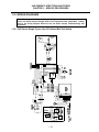
1
24G Series Flatbottom
Gas Fryers
Service & Parts Manual
Models 1824G, 2424G and 1824/2424G
Systems with Built-In Filtration
NON-CE
&
Frymaster Dean, a member of the Commercial Food Equipment Service Association,
recommends using CFESA Certified Technicians.
PRINTED IN THE USA
[email protected]
24-Hour Service Hotline
1-800-551-8633
www.frymaster.com
JUNE 2007
*8196031*
Please read all sections of this manual and retain for future reference.
This product has been certified as commercial cooking equipment and MUST be installed by
professional personnel as specified. Installation, maintenance and repairs should be performed
by your FRYMASTER DEAN FACTORY AUTHORIZED SERVICE CENTER.
DANGER
Do not store or use gasoline or other flammable vapors and liquids in the vicinity of this or any
other cooking appliance.
DANGER
Instructions explaining procedures to be followed MUST be posted in a prominent location in
the event the operator detects a gas leak. This information can be obtained from the local gas
company or gas supplier.
WARNING
Improper installation, adjustment, alteration, service or maintenance can cause property
damage, injury or death. Read the installation, operating and maintenance instructions
thoroughly before installing or servicing this equipment.
DANGER
Safe and satisfactory operation of your equipment depends on proper installation. Installation
MUST conform with local codes, or in absence of local codes, with the National Fuel Gas Code,
ANSI Z223.1; The Natural Gas Installation Code, CAN/CGA-B149.1; The Propane Installation
Code, CAN/CGA-B149.2; or The latest edition of the National Electric Code, N.F.P.A. 70.
NOTICE
IF, DURING THE WARRANTY PERIOD, THE CUSTOMER USES A PART FOR THIS ENODIS
EQUIPMENT OTHER THAN AN UNMODIFIED NEW OR RECYCLED PART PURCHASED
DIRECTLY FROM FRYMASTER DEAN, OR ANY OF ITS AUTHORIZED SERVICE CENTERS,
AND/OR THE PART BEING USED IS MODIFIED FROM ITS ORIGINAL CONFIGURATION, THIS
WARRANTY WILL BE VOID. FURTHER, FRYMASTER DEAN AND ITS AFFILIATES WILL NOT BE
LIABLE FOR ANY CLAIMS, DAMAGES OR EXPENSES INCURRED BY THE CUSTOMER WHICH
ARISE DIRECTLY OR INDIRECTLY, IN WHOLE OR IN PART, DUE TO THE INSTALLATION OF
ANY MODIFIED PART AND/OR PART RECEIVED FROM AN UNAUTHORIZED SERVICE CENTER.
DANGER
The crumb tray in fryers equipped with a filter system must be emptied into a fireproof container
at the end of frying operations each day. Some food particles can spontaneously combust if left
soaking in certain shortening material. Additional information can be obtained in the filtration
manual included with the system.
DANGER
The front ledge of the fryer is not a step. Do not stand on the fryer. Serious injury can result
from slips or contact with the hot oil.
WARNING
Drawings and photos used in this manual are intended to illustrate operational, cleaning and
technical procedures and may not conform to on-site management operational procedures.
WARNING
No structural material on the fryer should be altered or removed to accommodate placement of
the fryer under a hood. Questions? Call the Frymaster Dean Service Hotline at 1-800-551-8633.
This equipment is to be installed in compliance with the basic plumbing code of The Building
Officials and Code Administrators International, Inc. (BOCA) and the Food Service Sanitation
Manual of the Food and Drug Administration.
COMPUTERS (WHERE APPLICABLE)
FCC
This device complies with Part 15 of the FCC rules. Operation is subject to the following two conditions:
1) This device may not cause harmful interference, and 2) This device must accept any interference
received, including interference that may cause undesired operation. While this device is a verified Class
A device, it has been shown to meet the Class B limits.
CANADA
This digital apparatus does not exceed the Class A or B limits for radio noise emissions as set out by the
ICES-003 standard of the Canadian Department of Communications.
Cet appareil numerique n’emet pas de bruits radioelectriques depassany les limites de classe A et B
prescrites dans la norme NMB-003 edictee par le Ministre des Communcations du Canada.
DANGER
THIS PRODUCT CONTAINS CHEMICALS KNOWN TO THE STATE OF CALIFORNIA TO CAUSE
CANCER AND/OR BIRTH DEFECTS OR OTHER REPRODUCTIVE HARM.
Operation, installation, and servicing of this product could expose you to airborne particles of
glasswool or ceramic fibers, crystalline silica, and/or carbon monoxide. Inhalation of airborne
particles of glasswool or ceramic fibers is known to the State of California to cause cancer.
Inhalation of carbon monoxide is known to the State of California to cause birth defects or other
reproductive harm.
WARNING
Do not bang fry baskets or other utensils on the fryer’s joiner strip. The strip is present to seal
the joint between the fry vessels. Banging fry baskets on the strip to dislodge shortening will
distort the strip, adversely affecting its fit. It is designed for a tight fit and should only be
removed for cleaning.
24G Series Flatbottom Gas Fryers
Service & Parts Manual
TABLE OF CONTENTS
PAGE #
1.
1.1
1.2
1.3
1.4
1.5
1.6
1.7
1.7.1
1.7.2
1.7.3
1.7.4
1.7.5
1.7.6
1.8
1.8.1
1.8.2
1.8.3
1.8.4
1.8.5
1.9
1.9.1
1.9.2
1.9.3
1.10
1.10.1
1.10.2
1.10.3
1.10.4
1.10.5
1.10.6
1.10.7
1.10.8
1.10.9
SERVICE PROCEDURES
Functional Description
Accessing Fryers for Servicing
Cleaning Gas Valve Vent Tube
Adjusting Burner Manifold Gas Pressure
Adjusting Pilot Flame
Calibrating the Thermatron Temperature Controller
Replacing Fryer Components
Remove/Replace Temperature Probe or High-Limit Thermostat
Removing /Replacing Rocker Switches
Replacing the Gas Valve
Replacing the Pilot Assembly or Direct Spark Ignitor
Removing/Replacing Blower Assembly or Air Prover Switch
Replacing the Frypot
Troubleshooting and Problem Isolation
Ignition Failures
Improper Burner Functioning
Improper Temperature Control
Filtration Problems
Leakage
Troubleshooting Guides
Pilot Burner Malfunctions
Main Burner Malfunctions
Indicator Lights
Wiring Diagrams
24G Series Single Fryers, Non-CE with out Boil Switch
24G Series Single Fryers, Non-CE with Boil Switch
24GTI with Drain Safety Switch, and Boil Out Option Enabled LJS
24GTI with Drain Safety Switch, and Boil Out Option Enabled 120V non-LJS
24GTI with Drain Safety Switch, and Boil Out Option Enabled 250V non-LJS
24GTI with Drain Safety Switch, and Boil Out Option Disabled KFC
24GTI with Drain Safety Switch, and Boil Out Option Disabled non-KFC
24G Series Single Fryers, CE Approved
24GTI Oil Return/Filter System
1–1
1–1
1–5
1–6
1–6
1–7
1–7
1–9
1–9
1–11
1–12
1–12
1–13
1–15
1–19
1–20
1–21
1–23
1–23
1–25
1–26
1–26
1–27
1–28
1–29
1–29
1–30
1–31
1–32
1–33
1–34
1–35
1–36
1–37
24G Series Flatbottom Gas Fryers
Service & Parts Manual
TABLE OF CONTENTS (cont.)
PAGE #
2.
2.1
2.2
2.3
2.3.1
2.3.2
2.3.3
2.4
2.5
2.5.1
2.5.2
2.6
2.7
2.8
PARTS LIST
Blower Assembly, Combustion Air
Burner Manifold and Related Components
Cabinetry
Backs, Bases, Casters, Sides, Etc.
Door Assemblies and Component Parts
Flue Caps, Top Caps, and Related Components
Control Panels, Wireways, and Related Components
Filtration
Under Fryer Filter (UFF) Components
ND90 Built-In Filter System Components
Frypot, Drain and Oil-Return Components
Drain Valve and Components
Wiring Connectors, Pin Terminals and Power Cords
2–1
2–1
2–2
2–4
2-4
2-6
2-8
2–10
2–12
2–12
2–17
2–20
2–22
2–23
THIS PAGE INTENTIONALLY LEFT BLANK
24G SERIES FLATBOTTOM GAS FRYERS
CHAPTER 1: SERVICE PROCEDURES
1.1 Functional Description
24G Series Flatbottom gas fryers contain a welded steel frypot (mild steel) with heat-transfer ducting
on the frypot bottom for efficient heating of oil without scorching. A draft inducer draws air over
the burners for combustion. Air movement directs the combustion products back and forth across
the frypot bottom by means of a set of baffles, transferring the heat evenly. Cold air is prevented
from entering the combustion chamber and cooling the oil during the coasting cycle.
Flames originate from orifices in three tubular burners positioned at the front and beneath the frypot.
The diameter of the orifices differs for Natural (CE:G20/G25) and LP (CE:G31) gas as indicated in
the table below.
NON-CE (Altitudes of 2000 feet or less)
MODEL
INPUT
(BTU)
GAS TYPE
ORIFICE
[DRILL SIZE (MM)]
ORIFICE
PART #
QTY
1824/2424G
120
NAT
LP
#34 (2.82)
#50 (1.78)
810-2051
810-2317
3
3
EQUIPMENT
PRESSURE
MBAR
INCH W.C.
10
27.5
4
11
CE ONLY (Altitudes of 2000 feet or less)
MODEL
INPUT
(kW)
GAS TYPE
ORIFICE
(MM)
ORIFICE
PART #
QTY
1824/2424G
30,0
(88,000
BTU)
G20
G25
G31
2,50
2,50
1,60
810-2628
810-2628
810-2317
3
3
3
1-1
EQUIPMENT
PRESSURE
MBAR
INCH W.C.
14,5
21,0
31,0
5,8
8,4
12,44
24G SERIES FLATBOTTOM GAS FRYERS
CHAPTER 1: SERVICE PROCEDURES
An electromechanical gas valve regulates gas flow to the manifold. 24G Series Flatbottom gas
fryers are equipped with either a 120-volt valve system (standing pilot) or a 24-volt valve system
(electronic ignition or CE standing pilot). Units may be configured with either a pilot ignition system
(standing pilot) or an electronic ignition system (direct spark ignition).
Pilot System Configuration
The pilot system is comprised of the pilot orifice, pilot hood, and a thermocouple. The pilot serves
two purposes. The first is to light the burner, the second is to heat the thermocouple. In operation,
the thermocouple is in contact with the pilot flame and generates millivolts. The millivolt output
energizes the gas valve pilot coil, which in turn opens the pilot valve. If the pilot flame is
extinguished, voltage is lost to the gas valve pilot coil and the pilot valve closes. The gas valve is
constructed so that the main valve will not open if the pilot valve is not open. The pilot flame must
be manually lit when the fryer is first placed into operation. A separate circuit, activated by the fryer
ON/OFF switch, provides voltage through the Thermatron temperature controller to the gas valve
main coil, which opens the main valve.
Main Coil
Gas
Valve
Pilot Coil
11
10
9
3
AC2
2
3A 2A 1A
EXT POT
8
Pilot
Line Voltage
6
5
1
AC1
7
High-Limit
Thermostat
PROBE
12 13
14
NO COM NC
RELAY
Thermocouple
MELT CYCLE DISABLE
Thermatron Temperature
Controller
ON/
OFF
Switch
Line Voltage
The Pilot System
120V
Electronic Ignition Configuration
In units configured for electronic ignition, an ignition module connected to an ignitor assembly
replaces the pilot system. The ignition module performs three important functions: it provides an
ignition spark, supplies voltage to the gas valve, and proofs the burner flame.
The module contains a time delay circuit and a coil that activates the gas valve. The ignitor
assembly consists of a spark plug and a flame sensor element.
At start-up the ON/OFF switch is placed in the "ON" position, supplying 115 VAC or 230 VAC,
according to system configuration, to the Thermatron interface board. The voltage is stepped down
1-2
24G SERIES FLATBOTTOM GAS FRYERS
CHAPTER 1: SERVICE PROCEDURES
via transformer to 24 VAC before entering the ignition module. If resistance in the temperature
probe indicates the temperature in the frypot is below 150°F (66°C), the current flows through a melt
cycle circuit where a switch alternately closes for approximately 4 seconds and opens for
approximately 20 seconds. If the temperature is 150°F (66°C) or above, the current flows through a
heat circuit, bypassing the timer switch. In either case, current is supplied to the other leg of the heat
relay coil, which then closes an electronic switch in the 24 VAC circuit to provide current to the
ignition module.
Circuitry in the ignition module sends 24 VAC current to the gas valve via a normally closed highlimit switch and a drain safety switch. Simultaneously, the module causes the ignitor to spark for up
to 11 seconds to light the burner flame. A flame sensor verifies that the burner is lit by measuring
the flow of microamps through the flame. If the burner does not light (or is extinguished), current to
the ignition module is interrupted, preventing the main valve from opening, and the ignition module
"locks out" until the power switch is turned "OFF", then back "ON".
A temperature probe monitors the temperature in the frypot. When the programmed setpoint
temperature is reached, resistance in the probe causes the heat cycle circuitry in the controller to
interrupt current flow through the heat relay. This in turn interrupts the 24 VAC to the ignition
module, resulting in closure of the gas valve.
Control Options
24G Series Flatbottom gas fryers are equipped with Thermatron temperature controller. The fryer is
turned on and off by means of a rocker switch and the temperature is set by adjusting a
potentiometer. The Thermatron board is located in the wireway box behind the control panel, or in a
component box inside the cabinet (depending on fryer configuration).
The Thermatron temperature controller operates by comparing resistance between the potentiometer
setting and the temperature probe. If the resistance values don’t match, an on-board relay energizes,
sending voltage to the gas valve, which supplies fuel to the burners. When the resistance values are
equal, the on-board relay de-energizes, interrupting voltage to the gas valve, which stops the fuel
flow.
Depending on the system configuration and destination, 24VAC, 115VAC or 208/230VAC
controller boards are used.
1-3
AC2 3A 2A 1A
EXT POT
AC1
5
6
1
2
3
7
8
9
Not used
10 11 12 13
14
PROBE NO COM NC
RELAY
24G SERIES FLATBOTTOM GAS FRYERS
CHAPTER 1: SERVICE PROCEDURES
MELT CYCLE DISABLE
Thermatron Controller Board
Line voltage enters the interface board at terminals 1 and 3. The temperature controls
(potentiometer) are connected to terminals 7, 8 and 9. The sensor probe circuit is connected to
terminals 10 and 11. The high-limit and gas valve routes through terminal 12. Terminals 2 and 13
are jumped out. Terminals 5 and 6 are the melt-cycle disable circuit. The melt cycle is enabled
unless terminals 5 and 6 are jumped out.
1-4
24G SERIES FLATBOTTOM GAS FRYERS
CHAPTER 1: SERVICE PROCEDURES
Safety Components
All 24G Series Flatbottom gas fryers are equipped with a high-limit thermostat. In the event that the
fryer fails to properly control the oil temperature, the high-limit thermostat prevents the fryer from
overheating to flash point. The high-limit thermostat acts as a normally closed power switch that
opens when exposed to temperatures above 410°F [(210°C)- CE] to 435°F [(224°C)- Non-CE]. CE
and non-CE high-limits are not interchangeable.
Frying systems with built-in filtration are equipped with drain microswitches that disable the fryer if
the drain valves are not completely closed. Opening a drain valve (i.e. filtering or draining the fryer)
automatically opens the reset switch circuit. The drain valve must be fully closed prior to resetting
the safety switch.
1.2 Accessing Fryers for Servicing
DANGER
Moving a fryer filled with cooking oil/shortening may cause spilling or splattering of
the hot liquid. Follow the draining instructions included with the fryer before
attempting to relocate a fryer for servicing.
NOTE: Perform the following only if the fryer cannot be serviced in its installed location. Some of
the following service procedures require the fryer to be connected to the gas and/or electrical supply.
1. Shut off the gas supply to the unit. Unplug the power cords. Remove any attached restraining
devices.
2. Disconnect the unit from the gas supply.
3. Relocate the fryer for service accessibility.
4. After servicing is complete, reconnect the unit to the gas supply, reattach restraining devices, and
plug in the electrical cords.
1-5
24G SERIES FLATBOTTOM GAS FRYERS
CHAPTER 1: SERVICE PROCEDURES
1.3 Cleaning the Gas Valve Vent Tube (if applicable)
1. Set the fryer power switch and the gas valve to the "OFF" position.
2. Carefully unscrew the vent tube from the gas valve. NOTE: The vent tube may be straightened
for ease in removal.
3. Pass a piece of ordinary binding wire (.052 inch diameter) through the tube to remove any
obstruction. Remove the wire and blow through the tube to ensure it is clear.
4. Reinstall tube and bend so that the opening is pointing downward.
1.4 Adjusting Burner Manifold Gas Pressure
WARNING
This task should be performed by qualified service personnel only.
1. Ensure that the gas valve knob is in the
"OFF" position.
2. Remove the pressure tap plug from the
burner manifold.
3. Insert the fitting for a gas pressuremeasuring device into the pressure tap
hole.
Remove pressure tap from burner manifold to
check burner manifold pressure.
4. Place the gas valve in the "ON" position then place the fryer power switch in the "ON" position.
When the burner lights and continues to burn, note gas pressure reading for correct pressure in
accordance with the table on page 1-1.
1-6
24G SERIES FLATBOTTOM GAS FRYERS
CHAPTER 1: SERVICE PROCEDURES
5. To adjust burner gas pressure, remove the cap from the gas valve regulator and adjust to correct
pressure (arrows).
Pilot Ignition Valve (Line
Voltage)
Non-CE Electronic Ignition
Valve
CE Pilot Ignition Valve
6. Place the fryer power switch and the gas valve in the "OFF" position. Remove the pressuremeasuring device fitting from the pressure tap hole and reinstall the pressure tap plug.
1.5 Adjusting the Pilot Flame (where applicable)
1. Remove the cap from the pilot adjustment screw hole on the gas valve.
2. Using a small, flat-tipped screwdriver, turn the pilot adjusting screw counterclockwise to
increase length of flame or clockwise to decrease length of flame. Adjust to obtain a flame from
1 to 1-½ inches long.
3. Reinstall the pilot adjustment screw cap.
1.6 Calibrating the Thermatron Temperature Controller
1. Fill the frypot to the proper oil-level line with cooking oil/shortening. If solid shortening is used,
ensure that the shortening is properly packed and melted in the frypot before proceeding.
2. Ensure the fryer ON/OFF switch is in the "OFF" position, and then light the pilot.
3. Place the fryer ON/OFF switch in the "ON" position. Set the Thermatron dial to 325°F (162°C).
4. Allow the oil/shortening to equilibrate at setpoint temperature. This is evident when the burners
have cycled on and off several times.
1-7
24G SERIES FLATBOTTOM GAS FRYERS
CHAPTER 1: SERVICE PROCEDURES
5. Insert a good grade thermometer or pyrometer into the frypot within 3 inches of the probe bulb.
Ensure the tip of the thermometer/pyrometer does not touch the bottom or sides of the frypot.
6. If the temperature on the thermometer is higher or lower than 325°F (162°C), the dial is out of
calibration.
7. Calibrate the dial by first loosening two
setscrews in the dial (arrows). After
loosening both setscrews, slowly turn the
dial to match the temperature reading of
the thermometer. Tighten each setscrew,
ensuring the dial does not move on the
shaft during tightening.
8. Allow burners to cycle on and off several
times, then recheck oil temperature as
described in step #5. If the Thermatron
dial temperature matches the thermometer
temperature, the controller is calibrated.
If not, repeat step #7.
9. After calibration is complete, place the
fryer power switch in the "OFF" position
and disconnect the fryer from the
electrical supply.
Loosen two setscrews in dial (arrows) to recalibrate
controller.
1-8
24G SERIES FLATBOTTOM GAS FRYERS
CHAPTER 1: SERVICE PROCEDURES
1.7 Replacing Fryer Components
1.7.1 Remove/Replace Temperature Probe or High-Limit Thermostat
1. Disconnect the fryer from the electrical supply.
2. Allow the frypot to cool for 10 minutes before draining. Drain cooking oil/shortening from the
frypot. Allow the frypot to cool completely before proceeding.
3. Remove the fryer door(s) for access to control panel screws. Lift door up, disengage rod from
lower door bracket, and then remove door. (Current production models have spring-loaded door
pins. Disengage bottom pin from the hinge, and then remove door.)
4. Remove the marine edge (where applicable) from the topcap.
5. Support the control panel and remove
screws securing the panel to the wireway
box. Remove the control panel.
6. On units with switches/indicator lights on
the control panel, mark and unplug the
wiring, and then remove the control panel.
7. Remove screw securing probe/high-limit
access cover to wireway box. Remove
access cover and set aside.
Note: Some systems have a wiring terminal
block mounted on the access cover. Mark
and disconnect the wiring to the terminal
block before removing access cover.
1-9
24G SERIES FLATBOTTOM GAS FRYERS
CHAPTER 1: SERVICE PROCEDURES
8. Remove the sensor bulb guard to access the
probe and high-limit. Current production
systems have a sensor bulb clamp that must
be removed prior to removing the probe or
high-limit from the frypot.
9. On the sensor bulb being removed, loosen
and unscrew completely the compression
nut, then the pass-through nut from the
frypot. Carefully remove the sensor bulb
from the frypot, being careful not to damage
the remaining sensor bulb.
Temperature probe.
High-limit.
10. If removing the high-limit, remove the
screws securing it to the wireway box.
Mark and remove the wiring from the highlimit housing.
High-limit.
11. Reverse steps to install new temperature probe or high-limit. If reinstalling high-limit, ensure the
capillary tube is properly routed around the temperature probe before tightening (see photo, Step
#8). Reconnect wiring removed from defective high-limit.
1-10
24G SERIES FLATBOTTOM GAS FRYERS
CHAPTER 1: SERVICE PROCEDURES
IMPORTANT (High-Limit): When installing new high-limit, ensure the capillary tube and
bulb are positioned properly with the mounting hardware installed prior to tightening the
compression nut. Once tightened, the capillary tube cannot be repositioned.
IMPORTANT (Temperature Probe):
When installing new temperature probe,
ensure probe is positioned properly with the
mounting hardware installed (current
production systems), or 1/8" from frypot
bottom (older systems), prior to tightening
the compression nut. Once tightened, the
probe cannot be repositioned.
In older fryers, ensure probe tip is 1/8" from
frypot bottom for proper temperature sensing.
Frypot Bottom
1.7.2 Removing/Replacing Rocker Switches
1. Disconnect the fryer from the electrical supply.
2. If switches are located on front panel or control box, remove the screws securing panel. Do not
allow the panel to hang on the switch wiring harness; use some type of support.
3. Depress the retaining clips (see illustration below) and push the switch out of the slot. If there is
a switch-guard present, retain it for installation of the replacement switch.
W hen connecting wires to
replacement switch, pass the wires
through the switch guard (i f
applicable) before connecting to
switch.
Depress clips on each
end to remove switch
from control panel.
4. Remove wires one at a time from the switch being removed and connect to the replacement
switch until all wires are transferred.
5. Reverse the above steps for reassembly.
1-11
24G SERIES FLATBOTTOM GAS FRYERS
CHAPTER 1: SERVICE PROCEDURES
1.7.3 Replacing the Gas Valve
DANGER
Drain the frypot or remove drain valve handle to prevent accidental opening before
proceeding further.
1.
Disconnect fryer from electrical and gas supplies.
2.
Disconnect the wires from the gas valve terminal block, marking each wire to facilitate
reconnections. For 120VAC gas valves, disconnect the black wire from the high-limit, then
remove the bombtail connecting the white wire.
3.
Remove the high-limit thermostat wire from the gas valve pilot coil (all but 120VAC
valves).
4.
Remove the pilot gas line fitting from the gas valve.
5.
Remove the pipe union collars to the left and right of the gas valve and remove the valve.
6.
Remove the pipefitting from the old gas valve and install on the replacement valve, using
Loctite PST567 or equivalent pipe thread sealant on threads. Do not apply sealant to the
first two pipe threads. Doing so will clog and damage the gas valve.
7.
Reverse steps 1-5 to install the replacement gas valve.
1.7.4 Replacing the Pilot Assembly or Direct Spark Ignitor
1.7.4.1 Replacing Pilot Assembly
1. Remove the burner shield from the burner-box slots.
2. Remove the pilot tubing from the bottom of the pilot assembly.
3. Remove the mounting screw from the pilot mounting-bracket and remove the pilot.
4. Reverse the procedure to replace the pilot assembly. Ensure the replacement assembly is
properly positioned above the center burner tube before tightening mounting-bracket screw.
NOTE: The above procedure is applicable to standing pilot assemblies only.
1-12
24G SERIES FLATBOTTOM GAS FRYERS
CHAPTER 1: SERVICE PROCEDURES
1.7.4.2 Replacing Direct-Spark Ignitor Assembly (Units with Electronic Ignition Only)
1. Remove the burner shield from the
burner-box slots.
2. Disconnect sense wire and ignition cable
from the ignitor.
3. Remove the mounting screw from the
ignitor mounting-bracket and remove the
ignitor.
4. Reverse the procedure to replace the
ignitor assembly. Ensure the ignitor is
properly positioned in relation to the
center burner before tightening mounting
screw.
Ensure ignitor is properly positioned (arrow) over
the center burner prior to tightening the mounting
screw.
NOTE: The above procedure is
applicable to fryers equipped with
electronic ignition systems only.
1.7.5 Removing/Replacing Blower Assembly or Air Prover Switch
1. Remove back panel. On systems with
built-in filtration, use care not to damage
the oil-return heat-tape wiring insulation
when removing backs (multi-batteried
systems after 02/03 have two-piece back
panels; remove both to access blower
assembly).
Multi-batteried systems after 02/03 have upper
and lower back panels, which must be removed
to access the blower assembly (fryer above
shown with upper back panel removed).
1-13
24G SERIES FLATBOTTOM GAS FRYERS
CHAPTER 1: SERVICE PROCEDURES
2. Remove blower assembly by removing
four screws (two screws securing the flue
outlet to the firebox, and two screws
securing the blower inlet housing to the
firebox). Pull the assembly out of the slot
and lower to the side. Do not remove the
electrical connections at this time.
3. If replacing air prover switch, remove
junction box cover, mark and disconnect
wiring to the switch. Remove screws
securing the switch to the junction box,
and then remove the switch from the
blower housing.
Install new switch,
ensuring the switch flap is correctly
positioned in the blower housing.
Reattach wires removed from old switch
and replace box cover.
After removing screws (arrows), remove blower
assembly from firebox by pulling outward.
4. If replacing blower, remove junction box
cover, mark and disconnect each wire, and
remove conduit fitting from junction box.
Reinstall conduit fitting on new blower
and reconnect wiring. Replace box cover.
5. Reverse steps 1 – 4 to reinstall blower
assembly.
Blower junction box wiring. Mark wire locations
before disconnecting each wire.
1-14
24G SERIES FLATBOTTOM GAS FRYERS
CHAPTER 1: SERVICE PROCEDURES
1.7.6 Replacing the Frypot
Unit should be at room temperature, disconnected from gas and electrical service, and empty of oil
or shortening prior to beginning procedure.
1.7.6.1 Frypot Baffle Inspection
1. Remove cabinet door(s) by holding door and lifting up on hinge pin. Current production model
doors have spring-loaded pins that must be disengaged from the control panel and the bottom
hinge. Remove marine edge (if applicable) by lifting up and off topcap and set aside.
2. The burner-tube retainer strip and burner tubes must be removed from the frypot/firebox being
inspected. Remove the burner-tube shield and the burner-tube retainer from the burner-box and
set aside. Lift the burner tubes up over each orifice and then pull outward to remove.
3. Disconnect the pilot gas-supply tube and
remove the pilot assembly (without
electronic ignition), or disconnect the
sense wire and ignition cable and remove
the direct-spark ignitor assembly (with
electronic ignition). Inspect frypot baffles
for signs of burn-through or damage. If
baffle burn-through or damage is visible,
proceed to the next section. If not, and no
further service to frypot/firebox is
required, reverse the above steps to
reassemble the fryer.
Inspect frypot baffles through burner tube opening
(arrow) for signs of burn-through or damage.
1-15
24G SERIES FLATBOTTOM GAS FRYERS
CHAPTER 1: SERVICE PROCEDURES
1.7.6.2 Frypot/Firebox Removal/Replacement Procedure
1. Perform Procedure 1.7.5, Removing/Replacing Blower Assembly or Air Prover Switch, Steps 1
– 4.
2. Disconnect the union at the gas valve.
Remove four bolts connecting the burner
manifold brackets to the burner box.
Remove the burner manifold assembly
and set aside.
3. Mark and disconnect drain-valve
microswitch wiring. Remove elbow or
drain-tee assembly, and then remove the
drain valve/microswitch assembly.
Disconnect
union at gas
valve and
remove four
bolts (two per
side) to
remove burner
manifold.
Remove drain
elbow and
drain valve
assembly from
the frypot.
Disconnect union at gas valve and remove four
bolts connecting burner manifold brackets to
firebox, elbow and drain valve assembly from
frypot.
4. Remove two screws from control panel and lower, using care not to stretch or distort
switch/indicator light wiring (if applicable). If control panel is equipped with switches (see
Section 1.7.2, Removing/Replacing Rocker Switches, for detail), or indicator lights, mark and
disconnect wiring and set control panel aside.
Note: If equipped with indicator lights, use a pin-pusher to remove pins from main-harness
connector, and then remove control panel.
5. Perform Procedure 1.7.1, Remove/Replace Temperature Probe or High-Limit Thermostat, Steps
7 – 11.
1-16
24G SERIES FLATBOTTOM GAS FRYERS
CHAPTER 1: SERVICE PROCEDURES
6. Remove two screws securing topcap to
wireway box. Remove topcap. Remove
four screws securing wireway box to fryer
cabinet (arrows) and carefully lower
wireway box out of the way. Use care not
to stretch or distort the wiring.
7. Remove two screws from the firebox heat
shield (arrows), remove heat shield and
set aside.
NOTE: Steps 8 and 9 must be
performed prior to frypot removal,
especially on systems with built-in
filtration. Failure to perform these
steps will make frypot removal
extremely difficult, and cause possible
damage to firebox components during
removal.
Remove topcap, wireway box and front heat
shield to access firebox and frypot.
8. Remove the burner box baffle by pushing
the baffle up into the burner box until the
baffle studs are clear of the slots. Tilt the
baffle at an angle and remove it from the
burner box.
9. Remove screws (two) securing the flame
spreader to the burner box. Allow the
spreader to drop down to clear the frypot
baffles.
After removing burner-box baffle, remove screws
(two) securing the flame spreader to the burner
box. Allow the flame spreader to drop down in the
burner box to clear the frypot baffles. Repeat for
both sides.
1-17
24G SERIES FLATBOTTOM GAS FRYERS
CHAPTER 1: SERVICE PROCEDURES
10. Remove firebox back, along with
insulation from back of frypot. From the
rear of the unit, use a prying bar to
carefully pry the top assembly from the
frypot and cabinet frame (single units
only), and set aside. (The top assembly is
secured to the frypot with high-temp
silicone sealant.) On systems, remove
individual pieces on the frypot being
removed.
11. Pull the frypot back and up to remove. On
fryers with built-in filtration systems,
ensure the front oil-return inlet is clear of
the firebox front before lifting frypot out
of cabinet.
Use a prying bar
to remove top
assembly from
frypot (single
units only).
Remove the
firebox back and
insulation from
back of frypot.
If the Firebox Requires Replacement:
12. Remove screws (12) securing the firebox
to the cabinet braces (arrows). Lift the
firebox assembly back and up to remove
from cabinet.
Remove screws (arrows) securing the firebox to
the cabinet.
1-18
24G SERIES FLATBOTTOM GAS FRYERS
CHAPTER 1: SERVICE PROCEDURES
13. Install new firebox into cabinet. Replace
screws (12) removed during removal of
the old firebox. Use spray adhesive (Zep
Aero Tac High-Strength Spray Adhesive
or equivalent) to install new insulation in
firebox bottom as shown. The insulation
must not go above the top of the burnerbox center flange.
NOTE: Ensure the strip of insulation is
properly affixed to the front blowerhousing flange (arrow) prior to installing
frypot. Failure to install the insulation
strip will result in frypot-baffle burnout,
blower damage and fryer malfunction,
and will void all applicable warranties.
Install new insulation in firebox using spray
adhesive, ensuring good contact between
insulation and metal surfaces.
14. Install new frypot, using care not to
damage the firebox insulation. Ensure
the blower-housing insulation strip
remains in place after installing the new
frypot (arrow).
Reverse the above steps to reassemble the
fryer. Use high-temp silicone to re-install
the top assembly (single fryers) or joiner
strips, flue caps, etc. (systems).
Ensure blower-housing insulation strip remains in
place after installing the new frypot (arrow).
1.8 Troubleshooting and Problem Isolation
This section is intended to provide technicians with a general knowledge of the broad problem
categories associated with this equipment, and the probable causes of each. With this knowledge,
the technician should be able to isolate and correct any problem encountered.
Problems you are likely to encounter with 24G Series Flatbottom fryers can be grouped into five
categories:
1. Ignition failures
2. Improper burner functioning
3. Improper temperature control
4. Filtration problems
5. Leakage
1-19
24G SERIES FLATBOTTOM GAS FRYERS
CHAPTER 1: SERVICE PROCEDURES
The probable causes of each category are discussed in the following sections. Troubleshooting
guides are included in Section 1.9 to assist in identifying some of the more common problems.
1.8.1 Ignition Failures
Ignition failure occurs when the ignition module fails to sense a flame within the 11-second time
delay period and locks out. Turn the fryer off, locate and correct the problem, then turn fryer back
on to clear the module lock.
There are three primary reasons for ignition failure, listed in order of probability:
1. Problems related to the gas and/or electrical power supplies.
2. Problems related to the electronic circuits.
3. Problems related to the gas valve.
Problems Related to the Gas and/or Electrical Power Supplies
The main indicators of this are that an entire battery of fryers fails to light. Verify that the quick
disconnect hose is properly connected, the fryer is connected to power, the main gas supply valve is
open, and the circuit breaker for the fryer electrical supply is not tripped. Some fryers are equipped
with a fryer reset-switch that must be reset each time the fryer is turned off.
Problems Related to the Electronic Circuits
If gas and electrical power are supplied to the fryer, the next most likely cause of ignition failure is a
problem in the 24 VAC circuit of fryers equipped with electronic ignition systems, or in the pilot
system for those without electronic ignition. If the fryer is equipped with an Under Fryer Filter
(UFF) filtration system, first verify that the drain valve is fully closed. (The valve is equipped with a
microswitch that must be closed for power to reach the gas valve. Often, although the valve handle
appears to be in the closed position, the microswitch is still open.) If the valve is fully closed, or the
fryer does not have a filtration system, refer to the troubleshooting guides in this chapter.
Problems Related to the Gas Valve
If the problem is not in the 24 VAC circuit or pilot system, it is most likely in the gas valve itself, but
before replacing the gas valve refer to the troubleshooting guides in this chapter.
1-20
24G SERIES FLATBOTTOM GAS FRYERS
CHAPTER 1: SERVICE PROCEDURES
1.8.2 Improper Burner Functioning
With problems in this category, the burner ignites but exhibits abnormal characteristics such as
"popping", incomplete lighting of burner, fluctuating flame intensity, and flames "rolling" out of the
fryer.
"Popping" indicates delayed ignition. In this condition, the main gas valve is opening but the burner
is not immediately lighting. When ignition does take place, the excess gas "explodes" into flame,
rather than smoothly igniting.
The primary causes of popping are:
•
Incorrect or fluctuating gas pressure
•
Misdirected or weak pilot flame (non-electronic ignition)
•
Clogged burner orifices
•
Clogged burners
•
Inadequate make-up air
•
Heat damage to the controller or ignition module
•
An out-of-adjustment ignitor or broken ignition wire
•
A defective ignition module
If popping occurs only during peak operating hours, the problem may be incorrect or fluctuating gas
pressure. Verify that the incoming gas pressure (pressure to the gas valve) is in accordance with the
appropriate CE or Non-CE requirements listed in the Installation and Operation manual that came
with the fryer, and that the pressure remains constant throughout all hours of usage. Refer to
Adjusting Burner Manifold Pressure in Section 1.4 if burner manifold pressure is suspected of
being incorrect.
If popping is consistent during all hours of operation, verify that the pilot is properly positioned
above the burner orifice and that the pilot pressure is correct. Correct pilot pressure is indicated by a
flame 1 to 1½" long. Refer to Section 1.5 for pilot adjustment procedure.
On systems equipped with electronic ignition, verify that the ignitor is properly adjusted (electrode
tip and ignitor positioned properly over middle burner).
Clogged burners and burner orifices are also likely causes of delayed ignition. Clogged burners are
indicated by uneven flame or partial flame on the burner face. Clogged orifices are indicated by no
flame.
Another cause of popping is an insufficient air supply or drafts that are blowing the pilot flame away
from the burner. Check for "negative pressure" conditions in the kitchen area. If air is flowing into
the kitchen area, more air is being exhausted than is being replenished and the burners may be
starved for air.
1-21
24G SERIES FLATBOTTOM GAS FRYERS
CHAPTER 1: SERVICE PROCEDURES
If the fryer’s gas and air supplies are okay, the problem most likely is with one of the electrical
components. Examine the ignition module for signs of melting/distortion and/or discoloration due to
excessive heat build-up in the fryer. (This condition usually indicates improper flue performance.).
Also, examine the controller for the same conditions. A melted or distorted ignition module is
automatically suspect and should be replaced, but unless the condition causing excessive heat in the
fryer is corrected, the problem is likely to recur.
Next, ensure the ignition wire is connected properly at both ends and examine it for obvious signs of
damage. Again, if damage is due to excessive heat in the fryer, that problem must also be corrected.
DANGER
MAKE SURE YOU ARE HOLDING THE INSULATED HANDLE OF THE SCREWDRIVER
AND NOT THE BLADE. THE SPARKING CHARGE IS APPROXIMATELY 25,000
VOLTS.
Check for proper operation by disconnecting the wire from the ignitor, inserting the tip of a
screwdriver into the terminal, and holding it near the frame of the fryer as the power switch is placed
in the "ON" position. A strong, blue spark should be generated for at least 11 seconds.
Fluctuating flame intensity is normally caused by either improper or fluctuating incoming gas
pressure, but may also be the result of variations in the kitchen atmosphere. Verify incoming gas
pressure in the same way as for "popping", discussed in the preceding paragraphs. Variations in the
kitchen atmosphere are usually caused by air conditioning and/or ventilation systems starting and
stopping during the day. As air conditioning/ventilation systems start and stop, the pressure in the
kitchen may change from positive or neutral to negative, or vice versa. Changes in airflow patterns
may affect flame intensity.
Flames "rolling" out of the fryer are usually an indication of negative pressure in the kitchen. Air is
being sucked out of the fryer enclosure and the flames are literally following the air. If negative
pressure is not the cause, check for high burner-manifold gas pressure in accordance with the
procedures in Section 1.4. An obstructed flue or a faulty blower, which prevents the fryer from
properly exhausting, may also be the cause.
Excessively noisy burners, especially with flames visible above the flue opening, may indicate that
the burner gas pressure is too high or the gas valve vent-tube is blocked (if applicable). If the gas
pressure is correct, and the vent-tube is unobstructed (if applicable), the gas valve regulator is
probably defective.
1-22
24G SERIES FLATBOTTOM GAS FRYERS
CHAPTER 1: SERVICE PROCEDURES
1.8.3 Improper Temperature Control
Temperature control, including the melt cycle, is a function of several interrelated components, each
of which must operate correctly. The principal component is the temperature probe. Depending
upon the specific configuration of the fryer, other components may include the Thermatron board,
the controller itself, and the ignition module.
Improper temperature control problems can be categorized into melt cycle problems and failure to
control at setpoint.
Failure to Control at Setpoint
In fryers equipped with a Thermatron temperature controller, the
temperature probe improperly positioned. Other causes may be
potentiometer. Possible causes are that the potentiometer is out of
probe or Thermatron board is defective. Refer to Section 1.6 for
Thermatron temperature controller.
#1 problem may be with the
the Thermatron board or the
calibration, or the temperature
instructions on calibrating the
1.8.4 Filtration Problems
Whenever the complaint is "the pump is running, but no oil is being filtered", check the filter paper
or filter leaf (screen) connections and ensure they are properly connected. Ensure the filter paper or
filter leaf is not clogged with food debris or sediment, and is properly assembled.
If the pump motor overheats, a circuit breaker in the filter circuit will trip and the motor will not start
until it is reset. If the pump motor does not start after pressing the circuit breaker, press the red reset
switch located on the rear of the motor. If the pump then starts, something caused the motor to
overheat. Maybe several frypots were filtered one after the other and the pump got hot. Letting the
motor cool down for at least a half-hour is all that is required in this case. More often, the pump
overheated for one of the following reasons:
•
Shortening was solidified in the filter leaf or filter lines.
•
The operator attempted to filter unheated oil or shortening. Cold oil and shortening are thicker
and cause the pump motor to work harder and overheat.
If the motor runs but the pump does not, there is a blockage in the pump. An incorrectly assembled
filter leaf allows food particles and sediment to pass through the filter pan and into the pump. When
sediment enters the pump, the gears bind up causing the motor to overheat, tripping the thermal
overload. Solidified shortening in the pump will produce the same result.
1-23
24G SERIES FLATBOTTOM GAS FRYERS
CHAPTER 1: SERVICE PROCEDURES
A pump seized by debris or hard shortening must be disassembled, cleaned and reassembled as
follows:
1. Disconnect power to the filter system.
2. Remove the front cover of the pump to access the gears inside, if the pump is accessible while
still inside the cabinet. If the front cover is not accessible, the pump must be removed from the
pump motor (remove input/output plumbing from the pump prior to removing pump). Remove
setscrews to disengage the pump from the motor.
Remove these bolts (6) to
remove pump cover.
Remove debris or hardened
shortening to free gears.
3. Prior to reassembly, the inside housing must be clean and free of any sediment or debris. Failure
to completely clean the inside housing and ring gear will cause gear binding after reassembly.
4. During reassembly, partially install the housing bolts in a star pattern, leaving a ⅛-inch (3.18
mm) gap between the cover and housing flanges. Ensure there is no shortening or oil in the filter
pan, and that the filter pan is disconnected. With the motor running slowly draw the cover in,
evenly tightening the housing bolts. When the cover is snug on the housing tighten all bolts to
15 inch-lbs (1.7 Nm) ensuring that the pump is working correctly. Turn the motor off.
An incorrectly assembled or damaged filter leaf will allow food particles and sediment to pass
through and clog the pump. Particles large enough to clog the pump may indicate that the crumb
tray is not being used, and that the filter leaf is not properly assembled.
The electronics of the SUFF/UFF filtration systems are simple and straightforward. Microswitches,
attached to handles for each vat and wired in parallel, provide the 24 VAC required to activate the
pump relay coil when the handles are moved to the ON position. The activated pump relay coil pulls
in the pump motor switch, supplying power to the pump motor.
Filter systems equipped with oil-return heaters are wired into the 120 VAC source, which remain
energized as long as the unit is plugged in.
1-24
24G SERIES FLATBOTTOM GAS FRYERS
CHAPTER 1: SERVICE PROCEDURES
1.8.5 Leakage
Frypot leaks are usually due to improperly sealed high-limit, temperature probe or oil-return and
drain fittings. When installed or replaced, each of these components must be sealed with Loctite
PST567 sealant or equivalent to prevent leakage. In very rare cases, a leak may develop along one
of the welded corners of the frypot. When this occurs, the frypot must be repaired or replaced.
Frypot locations (indicated by arrows) where potential leaks could occur.
1-25
24G SERIES FLATBOTTOM GAS FRYERS
CHAPTER 1: SERVICE PROCEDURES
1.9 Troubleshooting Guides
FACTORY APPROVAL MUST BE OBTAINED PRIOR TO ANY WARRANTY WORK BEING
DONE OR DEAN CANNOT BE HELD RESPONSIBLE.
The following procedures must be performed by Factory Authorized Service Technicians, and are
provided as an aid to expedite troubleshooting and repair of 24G Series frying systems.
1.9.1 Pilot Burner Malfunctions
PROBLEM
CORRECTIVE ACTION
Pilot will not ignite; no
evidence of gas at pilot
burner.
1. Ensure the combination gas valve is in PILOT position and that
gas is available at the control valve (check quick-disconnect
and/or gas-line connections).
2. Remove pilot gas supply line and check for dirt. Blow out with
compressed air if necessary, then reinstall.
3. Check pilot burner orifice for dirt.
Pilot burner ignites but
will not remain lit when
gas knob is released.
1. Check that the lead from the thermocouple is tightly screwed
into the pilotstat power bushing on the gas control.
2. Remove end of thermocouple lead from pilotstat power unit
bushing and clean with fine sandpaper. Also check that
bushing is clean.
3. Thermocouple possibly defective (millivolt output should be 1228mv); replace.
4. Pilot flame may be adjusted incorrectly. Adjust flame to 1-½"
high by turning pilot flow adjustment screw.
Pilot burner ignites
properly and burns
properly, but goes out
when the exhaust
blower comes on.
1. With the exhaust blower in operation, the extra air causes the
pilot to blow out. The pilot assembly may be too low between
the burners. Adjust the pilot assembly to where the pilot hood
is above the burners.
2. Pilot flame may be adjusted too high and is on the verge of
blowing out. Re-adjust lower.
3. Pilot flame may be adjusted too low, even though it appears to
be satisfactory. Re-adjust higher as described earlier.
1-26
24G SERIES FLATBOTTOM GAS FRYERS
CHAPTER 1: SERVICE PROCEDURES
1.9.2 Main Burner Malfunctions
PROBLEM
Main burner will not
come on even though
air blower is in
operation; no gas
pressure at main
burner.
CORRECTIVE ACTION
1. Check that the combination gas valve is ON.
2. Check that the pilot is lit and is operating properly.
3. Check high temperature safety switch. Replace if defective.
4. Check air prover switch (sail switch) as follows:
Move actuating lever at switch to ensure it is not dragging in
the slots (use long tool to avoid burns). If so, bend the arm
carefully to clear the obstruction. Check the air prover switch
for continuity and replace if defective.
Air blower is not
operating, although
power is present at the
fryer.
1. Cooked product or other material may have fallen into the flue
and lodged in the blower wheel, preventing it from turning.
Clean out flue and blower wheel.
2. Blower motor may have overheated and shut off. This
condition will correct itself when motor cools (20 minutes). If
problems with blower overheating persist, call for service.
3. If fryer is equipped with a Thermatron controller, the
temperature probe or the controller board may be defective.
Main burner flames are
small and appear lazy;
Oil does not come up
to temperature quickly.
1. Check gas pressure at the pressure tap of the burner manifold.
Use a standard water-type U-gauge manometer. With the
burner in operation, the pressure should be about 4" W.C. on
natural and 11" W.C. on propane (LP) gases. If not, unscrew
the cover of the pressure regulator adjustment and turn the
adjusting screw clockwise to increase gas pressure (or
counterclockwise to decrease the pressure). Replace cover
and plug.
There are signs of
excessive frypot
temperature;
oil becomes
discolored quickly.
1. Check the frypot for excessive build up of debris.
2. Check Thermatron controller; may be out of calibration. Recalibrate in accordance with instructions in Section 1.6.
3. Check gas pressure.
4. Oil of inferior quality or used too long. Replace with quality oil.
1-27
24G SERIES FLATBOTTOM GAS FRYERS
CHAPTER 1: SERVICE PROCEDURES
1.9.3 Indicator Lights
The fryer’s indicator lights serve a diagnostic purpose. All lights are lit when the fryer is working
properly. (The green light on the control panel will cycle on and off as the fryer calls for heat). Use
the following procedures to isolate problems indicated by light combinations.
Turn the temperature dial to 400°F (204°C) to ensure the sensor will demand heat. Check all
indicator lights in the fryer cabinet and on the control panel. [Older units may have power and reset
switches with different colored lights (orange, amber, red, etc.). Substitute the light color of the old
switch with the respective "green light" switch in the following troubleshooting procedures. The
control panel light colors haven’t changed.]
When turning the power switch "ON" and resetting the safety (reset) switch, check for the following:
LIGHT INDICATION
GREEN LIGHT/POWER SWITCH IS
"ON"
GREEN LIGHT/SAFETY (RESET)
SWITCH IS "OFF"
PROBABLE CAUSE
1.
The drain valve is open.
2.
The drain switch is defective.
1.
2.
CORRECTIVE ACTION
1.
Ensure the drain valve is
completely closed, and then
turn the reset switch to "ON".
No power to fryer.
1.
Check power source, power
cords and breaker. Ensure that
electricity is available to the
fryer.
Fuse is blown.
2.
Replace fuse.
3.
If fryer does not function after
resetting the reset switch,
contact a Factory Authorized
Service Center for assistance.
GREEN LIGHT/CONTROL PANEL IS
"OFF"
RED LIGHT/CONTROL PANEL IS
"OFF"
GREEN LIGHT/POWER SWITCH IS
"OFF"
GREEN LIGHT/SAFETY (RESET)
SWITCH IS "OFF"
GREEN LIGHT/ CONTROL PANEL IS
"OFF"
RED LIGHT/CONTROL PANEL IS
"OFF"
3.
Reset switch circuit defective.
1-28
24G SERIES FLATBOTTOM GAS FRYERS
CHAPTER 1: SERVICE PROCEDURES
1.10 WIRING DIAGRAMS
Note: The diagrams in this section depict wiring as of the date of manual publication.
It may not reflect design changes made to the equipment after publication. Always
refer to the wiring diagram affixed to the unit when actually troubleshooting this
equipment.
1.10.1 24G Series Single Fryers: Non-CE without Boil-Out Switch
1-29
24G SERIES FLATBOTTOM GAS FRYERS
CHAPTER 1: SERVICE PROCEDURES
1.10.2 24G Series Single Fryers: Non-CE with Boil-Out Switch
1-30
24G SERIES FLATBOTTOM GAS FRYERS
CHAPTER 1: SERVICE PROCEDURES
1.10.3 24GTI With Drain Safety Switch, and Boil-Out Option Enabled- LJS
1-31
24G SERIES FLATBOTTOM GAS FRYERS
CHAPTER 1: SERVICE PROCEDURES
1.10.4 24GTI With Drain Safety Switch, and Boil-Out Option Enabled- 120V Non-LJS
1-32
24G SERIES FLATBOTTOM GAS FRYERS
CHAPTER 1: SERVICE PROCEDURES
1.10.5 24GTI With Drain Safety Switch, and Boil-Out Option Enabled- 250V Non-LJS
1-33
24G SERIES FLATBOTTOM GAS FRYERS
CHAPTER 1: SERVICE PROCEDURES
1.10.6 24GTI With Drain Safety Switch, and Boil-Out Option Disabled – KFC
1-34
24G SERIES FLATBOTTOM GAS FRYERS
CHAPTER 1: SERVICE PROCEDURES
1.10.7 24GTI With Drain Safety Switch, and Boil-Out Option Disabled – Non-KFC
1-35
GRN
1-36
1
2
1
2
230V
BLK #2
WHT #2
BLU
POT
24V
Transformer
5 Amp Fuse
2 Pin Connector
(Amp)
WHT
BLK
Temperature
Probe
BLK #2
WHT
BLU
BLK
Power Switch
SPST
BLU
WHT
BLK
PUR
YLW
ORG
BLK
WHT
WHT
BLK
13
2
14
7
8
9
10
11
12
3
1
24V
Thermatron
Controller
1 2 3 4 5 6 7 8 9
1 2 3 4 5 6 7 8 9
BRN
WHT
MOTOR
Blower Motor
Assembly
WHT
BLK
BRN
WHT
BLK #2
RED
8
5
7
BRN
BLU
PUR
2
4
6
8
1
3
5
7
BRN
PUR
BRN
PUR
High-Limit
Thermostat
RED
6
3
24VAC
Relay
2
4
1
24VAC
Relay
WHT
NC
NO
BLU
BLU
Solder
Connection
Drain Valve
Safety Switch
Air Prover Switch
PUR
24VAC to Oil
Return Circuit
BRN
230 VAC
Valve Adapter
Gas Valve
24 VAC/50 Hz
Threaded to Valve
Thermocouple
ECO Connector
Assembly
G31 Propane (LP)
G20, G25 Nat Gas
24G SERIES FLATBOTTOM GAS FRYERS
CHAPTER 1: SERVICE PROCEDURES
1.10.8 24G Series Single Fryers: CE-Approved
24G SERIES FLATBOTTOM GAS FRYERS
CHAPTER 1: SERVICE PROCEDURES
1.10.9 24GTI Oil Return/Filter System
1-37
THIS PAGE INTENTIONALLY LEFT BLANK
24G SERIES FLATBOTTOM GAS FRYERS
CHAPTER 2: PARTS LIST
2.1 Blower Assembly, Combustion Air
5
6
2
1
3
4
ITEM
1
2
3
4
5
6
PART #
807-3573
807-3920
807-3746
823-3162
200-1428
823-3166
200-1471
COMPONENT
Motor, Blower Assembly
120V (Non-CE)
230V (CE)
Switch, Sail (Air Prover Switch)
Duct Assembly, Inlet
Gate, Air Flow
Duct Assembly, Outlet
Door, Outlet Duct Access 2424
2-1
24G SERIES FLATBOTTOM GAS FRYERS
CHAPTER 2: PARTS LIST
10
25
24
23
18
22
2
3
16
1
4
15
17
14
6
13
12
5
7
21
11
9
8
19
20
2.2 Burner Manifold and Related Components
2-2
24G SERIES FLATBOTTOM GAS FRYERS
CHAPTER 2: PARTS LIST
ITEM
PART #
COMPONENT
1
2
3
4
810-2129
200-1670
810-2168
Tube, Burner
Support, Left or Right Manifold
Burner Manifold Assembly
Orifice
2.82mm (#34) Natural Gas
1.78mm (#50) Propane (LP) Gas
Plug, ⅛-inch NPT (Manifold Pressure Tap Plug)
Union, ¾-inch NPT Pipe
Nipple, ¾-inch NPT X 4½-inch
Elbow, 90° X ¾-inch NPT
Nipple, ¾-inch NPT X 2-inch
Elbow, 90° X ¾-inch NPT Street
Valve, Gas
24V Natural (G20/G25) Honeywell
24V Propane (LP) (G31) Honeywell
120V Natural (G20/G25) Robertshaw
120V Propane (LP) (G31) Robertshaw
Vent tube
Bushing, ¾-inch NPT to ½-inch NPT
Nipple, ½-inch NPT X Close
Union, ½-inch NPT Pipe
Elbow, 90° X ½-inch NPT Street (for single fryers, use 45° 813-0342)
Nipple, ½-inch NPT X 2½-inch
Elbow, 90° X ½-inch NPT
Nipple, ½-inch NPT X 29¾-inch (single fryers, use 24½-inch 813-0788, 813-0729 23”)
Electronic Ignition Components
Ignitor and Flame Sensor Assembly (does not include flame sensor wire or cable)
Ignitor Bracket, Flat Style (After Oct 04)
Ignitor Bracket with bends (used prior to Oct 04.)
Flame Sensor Wire
Ignition Cable (includes 807-3742 cable and 807-3484 Rajah connector)
Module, Ignition (Spark Module) 11 sec. Honeywell
Screw, ¼-20 X ¾-inch (Pkg. of 10)
Nut, ¼-20 Nylock
Transformer, Electronic Ignition
Pilot Ignition Components
Pilot Burner
Non-CE Natural Gas (includes burner, thermocouple, gas line and bracket)
Non-CE Propane (LP) Gas #16 (Orifice Only)
CE Natural Gas (G20/G25)
Thermocouple
Non-CE (use 812-1284 for CE Thermocouple)
Gas Line, ¼-inch X 17½-inch
Bracket, Pilot Support
Piezo Ignitor Components (CE Units only)
Trigger
Electrode
Bracket
Lead, Trigger to Electrode
5
6
7
8
9
10
11
810-2827
810-2830
813-0154
813-0174
813-0300
813-0066
813-0112
813-0168
*
12
13
14
15
16
17
18
807-3555
807-3690
810-2156
810-2323
810-0691
813-0763
813-0022
813-0173
813-0165
813-0265
813-0062
813-0845
19
*
*
*
20
21
22
23
*
807-3556
106-4580
210-6184
106-1645SP
106-1644SP
807-0918
826-1389
809-0823
807-3551
24
106-0849SP
810-2400
812-1286
25
*
*
807-3550
810-0703
200-1416
*
810-1001
*
807-3540
*
200-1868
*
807-3650
*Not illustrated.
2-3
24G SERIES FLATBOTTOM GAS FRYERS
CHAPTER 2: PARTS LIST
2.3 Cabinetry
2.3.1 Backs, Bases, Casters, Sides, Etc.
2-4
24G SERIES FLATBOTTOM GAS FRYERS
CHAPTER 2: PARTS LIST
ITEM
PART #
1
200-1608
210-3006
2
823-3459
823-4349
823-3490
3
3a
4
5
6
7
823-3489
823-4350
823-3491
210-2977
210-1534
200-2903
823-4063
810-0357
810-2405
8
*
*
*
9
10
11
12
*
13
14
15
16
17
18
19
20
21
22
23
24
25
26
27
810-0356
810-2406
810-2053
826-1468
900-2949
200-1378
200-4511
200-4154
200-4153
200-4151
200-1607
210-1406
823-3581
823-3582
200-2632
200-2624
823-4149
200-5210
200-2717
200-2643
200-3356
200-5209
200-4696
823-4064
810-1365
106-2837SP
COMPONENT
Back, Single Fryer Cabinet
Standard 1824G (for 2424G, use 200-1500)
Short Flue 1824G (for 2424G, use 200-2005)
Panel, Left Side
Stainless Steel
Painted Mild Steel
Filter-Ready Add-On Fryer
Panel, Right Side
Stainless Steel
Painted Mild Steel
Filter-Ready Add-On Fryer
Cover, Side Panel Access
Rail, 1824G Cabinet Back Support (for 2424G, use Item 13) older units
Channel, 1824G Front and Rear Base
Support, Caster
Caster, 5-inch with Brake Swivel
4-Hole Bolt Pattern
Single Stud
Caster, 5-inch without Brake Swivel
4-Hole Bolt Pattern (for fryers with legs in front, use 810-0378 Rigid Caster)
Single Stud
Leg, 6-inch Adjustable
Kit, Shim Caster (contains 8 shims)
Shims, Caster 14 gauge
Bracket, Drain Nipple Storage
Hinge, Universal Door (for filter-ready units, use 200-1675)
Back, Lower Cabinet
Units with Built-in Filtration
1824G Units without Built-in Filtration (for 2424G, use 200-4152)
Back, 1824G Upper Cabinet (for 2424G, use 200-4150)
Back, 2424G One-Piece (used on UFF units built before February 2003 only)
Rail, 2424G Cabinet Back Support (for 1824G, use Item 4) older units
Panel, Inner Cabinet (Left)
Panel, Inner Cabinet (Right)
Support, Inner Cabinet Panel Front
Upright, Cabinet Rear
Support, Flue
Bridge, Filter Base
Support, Filter Pump Motor
Base, Filter
Cover, Filter Base
Brace, 2424G Rear Cross
Channel, 2424G Left or Right Base
Channel, Leg/Caster Support
Caster with Brake, 3-inch Adjustable
Bracket, Filter Retainer
* Not illustrated.
2-5
24G SERIES FLATBOTTOM GAS FRYERS
CHAPTER 2: PARTS LIST
2.3.2 Door Assemblies and Component Parts
5
6
6
4
2
11
3
10
9
7
1
8
A
B
ITEM
*
A
B
PART #
809-0413
106-2768
106-2816
COMPONENT
Spacer, Nylon (Universal Door Bushing)
**1824G Single-Pin Door Assembly (for 2424G, use 106-2769) 17.80”
1824G Double-Pin Door Assembly (for 2424G, use 106-2782)
Beg. 12/02 – 17.81”
1
824-1138SP Panel, 1824G Single-Pin Outer Door (for 2424G, use 824-1147)
2
200-4548
Panel, 1824G Single-Pin Inner Door (for 2424G, use 200-4549)
3
810-0180
Handle, Door (use 210-9739 for Euro look Handle)
4
809-0191
Washer, ¼-inch Lock
5
809-0918
Screw, 10-24 X ½-inch
6
810-1105
Magnet, Door
7
200-1301
Hinge Pin, Door
8
824-1146SP Panel, 1824G Double-Pin Outer Door (for 2424G, use 824-1147SP)
9
200-4610
Panel, 1824G Double-Pin Inner Door (for 2424G, use 200-4546)
10
826-1343
Spring, Door Hinge (qty. 10)
11
106-4067SP Hinge Pin and Keeper Assembly, Door
** Not illustrated.
** For units without inner door panels (built from 1993-2002), use 106-1751 for 1824G fryers or
106-1649 for 2424G fryers.
2-6
24G SERIES FLATBOTTOM GAS FRYERS
CHAPTER 2: PARTS LIST
THIS PAGE INTENTIONALLY LEFT BLANK.
2-7
24G SERIES FLATBOTTOM GAS FRYERS
CHAPTER 2: PARTS LIST
8
2-8
15
12
7
1
11
9
16
10
5
13
3
17
2
6
14
18
4
2.3.3 Flue Caps, Top Caps, and Related Components
24G SERIES FLATBOTTOM GAS FRYERS
CHAPTER 2: PARTS LIST
ITEM
PART #
1
2
3
4
5
6
7
106-3253SP
106-1638SP
823-4125
823-4127
106-2840SP
210-6177
823-3579
210-8244
210-8247
210-8248
210-8251
210-8245
210-8246
210-8250
210-8249
8
823-4907
9
10
11
12
13
14
15
16
823-4911
823-4915
823-4914
823-4913
823-4910
823-4909
210-4317
210-4313
210-4598
823-3622
823-3699
210-2028
823-3807
823-3497
823-3969
823-3495
823-3496
823-3964
17
823-4136
823-4137
823-4054
823-4139
823-4150
823-4152
823-4056
*
809-0477
18
823-3542
*
803-0209
*
803-0293
* Not illustrated.
COMPONENT
Frame, Single Crumb Dump
Frame, Double Crumb Dump
Insert, Pan Crumb Dump ½ Size
Tray, 12424 Single
Cover, 1824G Frypot (use 106-2839SP for 2424G Frypot)
Hanger, Basket
Deflector, Flue Cap Oil
For use on 1824G One-Piece Top Assembly (use 823-3474 for 2424G)
For use on 1-1824G Fryer (use 823-210-8171 for 2424G)
For use on 2-1824G with Crumb Dump
For use on 2-2424G with Crumb Dump
For use on 3-2424G with Crumb Dump
For use on 18L/24R with Crumb Dump
For use on 18R/24L with Crumb Dump
For use on 2-24L/18R with Crumb Dump
For use on 2-24R/18L with Crumb Dump
Flue Cap
For use on 1-1824G (use 210-7097 for LJS Short) (use 823-4908 for 2424G or
210-7085 for LJS Short)
For use on 2-1824G (use 823-4912 for 2424G)
For use on 3-2424G (3-Vat 2424G)
For use on 2-24/18R (3-Vat 24/18 System)
For use on 2-24/18L (3-Vat 24/18 System)
For use on 24L/18R 4-Vat 24/18 System
For use on 24R/18L 4-Vat 24/18System
Edge Strip, Frypot
Joiner Strip (joins frypots within a system)
Joiner Strip (joins one fryer system to another)
Top Assembly, One-Piece Short Flue 1824G (use 106-1619SP for 2424G) 3.83”
Top Assembly, One-Piece Standard Flue 1824G (use 823-3264 for 2424G) 9.94”
Top Cap, 1-1824G (use 210-7082 for 2424G)
Marine Edge for 1-1824G with Top Cap (use 823-3171 for 2424G)
Marine Edge (L-Shaped End-Cap)
1-1824G Notched Both Ends (use 823-3195 for 2424G)
2-2424G Notched Left End (use 823-3970 for notched right end)
2-2424G Notched Both Ends
3-2424G Notched Both Ends
24L/18R 4-Vat Fryer Notched Left End (use 823-3965 for notched right end)
Marine Edge (Solid End-Cap)
1-1824G Without Notches (use 823-4135 for FM emboss 2424G, or 823-4917
for DEAN emboss)
2-2424G Without Notches
2-2424G Notched Left End (use 823-4058 for notched right end)
3-2424G Without Notches
3-2424G Notched Left End (use 823-4151 for notched right end)
2-24/18L 3-Vat Fryer Without Notches
24L/18R 4-Vat Fryer Notched Left End (use 823-4157 for notched right end)
Screw, #10 x ¼ (used to attach Marine Edge)
Pan, Batter ⅓ with Lid
Brush, Frypot Cleaning
Gloves, Neoprene Hot Oil
2-9
24G SERIES FLATBOTTOM GAS FRYERS
CHAPTER 2: PARTS LIST
2.4 Control Panels, Wireways, and Related Components
2-10
24G SERIES FLATBOTTOM GAS FRYERS
CHAPTER 2: PARTS LIST
ITEM
PART #
1
106-0882
2
824-1140
3
823-4001
4
200-3167
5
807-1597
6
807-1321
7
807-3536
8
816-0217
9
810-1164
10
826-1359
11
826-1366
12
810-0045
13
807-2469
14
810-0678
15
807-0125
16
200-1671
17
826-1371
18
826-1680
19
807-3559
20
807-0800
21
106-2058SP
22
807-3611
23
807-3640
24
807-3613
25
200-1337
26
106-1966
27
816-0220
28
807-2103
29
106-2775
30
809-0247
31
200-4719
32
809-0853
33
809-0766
34
826-2086
35
809-0839
36
809-0834
37
210-3275
38
802-2134
39
816-0534
40
210-1985
41
820-0136
42
820-0135
43
210-3754
44
210-2716
45
807-3574
46
807-3576
47
807-3580
48
106-1978
49
106-4686
50
200-4602
51
210-2689
52
802-2085
53
200-3901
54
200-3356
*
807-3577
* Not illustrated.
COMPONENT
Probe, Thermostat Assembly, bottom 62.5” with connector (use 106-2607SP for 20” Top)
Vent, 1824G Wireway (use 824-1139 for 2424G)
Box, 1824G Wireway (use 823-4000 for 2425G)
Box, Remote Thermatron Adapter
Fuse, 3-amp Slow-Blow
Holder, Panel-Mount Fuse
Potentiometer, Temperature Control with spade terminals
Paper, Terminal Block Insulating
Terminal Block, 1-Piece Screwless
Screw, 4-40 X ¾-inch Slotted Round Head (Pkg. of 25)
Nut, 4-40 Keps (Pkg. of 25)
Bushing. .875-inch
Bushing, 1-inch
Bushing, .375-inch
Bushing, .50-inch
Cover, Thermostat Entry
Screw, #8 X .50-inch Slotted Hex Head (Pkg. of 25)
Clamp, Plastic Wire (Pkg. of 8)
Thermostat, 435°F High-Limit w/Manual Reset (use 807-3560 for 210°C CE units)
Transformer, Filter 120V/24V 50/60Hz 50VA
Relay Assembly, Boil-Out and Latch (use 106-1648SP for Bracket Switch Assembly)
Relay, Latch/Filter 24VAC Coil (Left Relay) (use 807-4114 for models after Oct 04)
Relay, Boil Out 120VAC Coil (Right Relay)
Spring, Relay Retaining
Bracket, Oil Return Relay
Socket Assembly, 24V Oil Return Relay (use 807-3612 for Relay Socket only)
Insulation, Microswitch
Microswitch, Straight Lever
Plate Assembly, Microswitch Adjustment
Nut, 8-32 Keps
Plate, Interface Board Mounting
Screw, 10-32 X 1.5-inch Slotted Pan Head
Nut, 10-32 Hex Head
Thermatron Board
Screw, 8-32 X .75-inch Slotted Pan Head
Nut, 8-32 Hex Locknut
Faceplate, 1824G Thermatron Blank (use 210-3168 for 2424G)
Label, Thermatron Faceplate
Knob, Thermatron Control
Faceplate, Single Fryer Thermatron Blank
Faceplate with Label, Old-Style Single Fryer 5.17” H x 4.04” W
Faceplate with Label, Old-Style SCF 3.13” H x 6.38” W
Control Panel, 1824G Two-Switch (use 210-4977 for 2424G)
Control Panel, 1824G Two-Lamp (use 210-2652 for 2424G)
Switch, Power ON/OFF Rocker
Switch, Momentary Reset
Switch, Boil-Out
Lamp Assembly, Red 120V 807-3581 lamp only (106-4687 230/250V)(106-4730 24V white)
Lamp Assembly, Green 120V 807-3582 lamp only (106-4686 230/250V)(106-4729 24V)
Box, Single Fryer Control
Plate, Single Fryer Control Panel
Label, Single Fryer Control Panel
Lid, Single Fryer Control Box
Cover, Single Fryer Control Box Access
Circuit Breaker, 7 amp
2-11
24G SERIES FLATBOTTOM GAS FRYERS
CHAPTER 2: PARTS LIST
2.5 Filtration
2.5.1 Under Fryer Filter (UFF) Components
29
26
16
26
10
a
29
27
26
10
a
30
28
10
a
25
Right-Flush configuration
illustrated.
10
19
23
22
2
19
18
21
20
24
19
106-1823SP Hose
Assembly
4
13
3
18
8
17
16
6
16
1
15
14
36
7
34
35
5
13
12
9
11
10
a
37
33
31
32
2-12
24G SERIES FLATBOTTOM GAS FRYERS
CHAPTER 2: PARTS LIST
ITEM
1
2
3
4
5
6
7
8
9
*
10
10a
11
12
13
14
15
16
17
18
19
20
21
22
23
24
25
26
27
28
29
30
PART #
810-2100
810-2098
810-2245
810-2173
813-0735
813-0632
810-2762
810-2562
810-2313
810-2307
813-0613
813-0614
106-3659SP
810-2125
201-6440
200-6202
106-3604
807-2103
816-0220
901-2348
902-2348
810-2170
813-0087
813-0165
813-0062
813-0625
813-0006
813-0156
813-0003
813-0093
813-0173
813-0673
813-0087
813-0833
810-2270
813-0730
813-0644
813-0631
810-2262
810-2308
810-2528
810-2691
810-2692
813-0452
COMPONENT
Motor, 120-230VAC ⅓-HP Filter Pump
Pump, 8 GPM Filter Haight
Hose, 16¾”x½”x½”Vacuum Filter Pan to Pump
Disconnect- Female, ½-inch
Reducer, ½-inch to ⅜-inch NPT Bell
Elbow, ⅜-inch NPT Street
Disconnect, ⅜-inch Female with Radial Collar
Coupling, Flare Tubing
Tubing, Flush (Right-Flush Configurations)
Tubing, Flush (Left-Flush Configurations)
Fitting, ½-inch X ½-inch 37° Flare
Fitting, ½-inch X ⅜-inch 37° Flare
Flush, Drain Valve Assembly, Complete
Valve, ⅜-inch Flush
Actuator Handle, Flush Valve (Left-Oriented Flush Valves Only)†
Actuator Handle, Flush Valve (Right-Oriented Flush Valves Only)†
Bracket Assembly, Microswitch Left Rear Flush (use 106-3682 for Right)
Microswitch, Straight Lever
Insulation, Microswitch
Cover, Microswitch (Left-Oriented Flush Valves Only)†
Cover, Microswitch (Right-Oriented Flush Valves Only)†
Disconnect, ½-inch Male Quick
Nipple, ½-inch X 1.50-inch NPT
Elbow, ½-inch X 90° NPT Street
Elbow, ½-inch X 90° NPT
Nipple, ⅜-inch X Close NPT
Bushing, ½-inch to ⅜-inch NPT Hex
Plug, ½-inch NPT Hex
Tee, ½-inch NPT
Nipple, ½-inch X 4-inch NPT
Union, ½-inch NPT
Nipple, ½-inch X 8.5-inch NPT
Nipple, ½-inch X 1.5-inch NPT
Nipple, ½-inch by 15.5-inch NPT
Tubing, Filter Pump to Rear Oil Return
Tee, ⅜-inch NPT
Nipple, ⅜-inch X 1.5-inch NPT
Elbow, ⅜-inch X 90° NPT
Tubing, Rear Oil Return
Tubing, 19.12”
Tubing, 21.65”
Tubing, 21.95”
Tubing, 56.27”
Tubing, 73.41”
Plug, ⅜-inch NPT Pipe
2-13
24G SERIES FLATBOTTOM GAS FRYERS
CHAPTER 2: PARTS LIST
ITEM
PART #
COMPONENT
31
823-4547
Handle, Drain Flush W/A
32
816-0549
Sleeve, Blue Vinyl (Drain Flush Handle Cover)
33
200-6135
Bracket, Flush Handle (Mounts to Inner Panel)
34
813-0251
Nipple, ½-inch by 4.5-inch NPT
35
809-0843
Cotter Pin
36
809-0885
Washer, Flat ⅜-inch x 1-inch x .083”
37
826-1374
Screw, #10 - ½-inch Hex Washer Head (Pkg. of 25)
* Not illustrated.
†
Valve stem pointing to left- left-oriented; Valve stem pointing to right- right oriented.
2-14
24G SERIES FLATBOTTOM GAS FRYERS
CHAPTER 2: PARTS LIST
5
4
3
2
1
ITEM
1
PART #
106-1693SP
810-2807
809-0428
809-0823
106-1692SP
COMPONENT
Filter Pan Caddy Assembly
Caster, 2-inch Rigid (use 810-2805 for 2-inch Swivel Caster)
Bolt, ¼-20 X ½-Inch Hex Head
Locknut, ¼-20
Filter Pan Complete (incl. Pan, Filter, Leaf, Crumb Basket and Lid) does not
include item #1.
2
3
823-3480SP
106-3675SP
810-2700
813-0867
810-2760
4
823-3509
5
823-3492
*
803-0002
*
810-2759
* Not illustrated.
Filter Pan With Fittings
Filter Leaf with Compression Cap & Riser Connection 11” x 19”
Quick Disconnect, ⅜-inch Male SS
Riser Standpipe Nipple, ⅜-inch X 6.5-inch S/S
Compression Cap with ⅜-inch NPT threads
Crumb Basket
Lid Assembly, Filter Pan
Powder, Filter 80 Individual Packs
Filter Screen Assembly only without standpipe parts.
2-15
24G SERIES FLATBOTTOM GAS FRYERS
CHAPTER 2: PARTS LIST
THIS PAGE INTENTIONALLY LEFT BLANK.
2-16
24G SERIES FLATBOTTOM GAS FRYERS
CHAPTER 2: PARTS LIST
2.5.2 ND90 Built-In Filter System Components
NOTES: Early model 24G fryers were available only as single units. To create multi-fryer
batteries, a number of single fryers were battered together with top connecting strips.
To provide built-in filtration for these batteries, a filter (with a dump station above it) was placed
somewhere in the middle, as shown in the photograph below. The filter system is referred to as the
44210ND90, or simply as the ND90.
The first generation filter returned the shortening to the frypot using a hose and wand assembly.
Later versions used a so-called “hands free” plumbing assembly attached to the backsplash of the
dump station.
The ND90 filter option was discontinued in 1996 when the fryer design was changed to incorporate
the Under Fryer Filter (UFF) system. A large number of ND90-equipped fryers were produced and
Frymaster/Dean continues to support them with replacement systems and parts, with the exception
that the “hands free” plumbing components are no longer available.
A complete filter kit, illustrated below, may be ordered to replace existing ND90 filters in the field.
The kit does not include the oil return hose and wand assembly. See page 2-19 for this part.
Part Number 44210ND90003
2-17
24G SERIES FLATBOTTOM GAS FRYERS
CHAPTER 2: PARTS LIST
21
20
13
6
2
40
26
30
28
13
32
25
15
27
22
29
33
2-18
DRAIN LINE PARTS
44
31
43
24
36
39
35
42
23
27
13
41
38
37
22
26
4
18
5
3
34
18
17
19
13
18
16
15
12
22
1
13
18
14
9
10
7
8
11
NOTE: The parts illustrated below are available as individual parts only. See page 2-17 for the
complete replacement filter assembly.
24G SERIES FLATBOTTOM GAS FRYERS
CHAPTER 2: PARTS LIST
ITEM
PART #
1
2
3
4
823-3637
810-2135
810-2136
810-2100
810-2252
810-2395
809-0428
809-0823
809-0189
5
200-3097
6
200-3096
7
823-4078SP
8
810-2237
9
106-1939SP
10
823-3646
11
823-3651
12
810-2762
*
816-0550
13
813-0625
14
813-0632
15
810-2125
*
230-0089
16
813-0634
17
813-0003
18
813-0022
19
810-0278
20
813-0345
21
810-2321
22
810-2172
23
813-0735
24
810-2375
25
813-0165
26
810-2170
27
810-2173
28
813-0654
29
823-3642
30
201-3105
31
202-3105
32
813-0631
33
810-2113
34
106-1454SP
35
210-3118
36
824-1090
37
807-3574
38
807-3577
39
807-1219
40
807-1224
41
813-0770
*
813-0760
*
813-0659
42
809-0884
43
816-0544
44
823-3652
*
200-1838
* Not illustrated.
COMPONENT
Filter Frame Assembly
Caster without Brake, 3-inch
Caster with Brake, 3-inch
Filter Pump and Motor Components
Motor, 120/230V 1/3 HP Filter Pump
Pump, 5GPM (use 810-2098 for 8GPM Pump)
Seal, Shaft (O-Ring)
Bolt, ¼-20 x ½-inch Hex Head (Motor Mount)
Nut, ¼-20 Nylock (Motor Mount)
Washer, ¼-inch Flat (Motor Mount)
Holder, Hose
Support, Pipe (Polish and Return Assemblies)
Pan Assembly, ND90 Series
Filter Leaf Assembly (includes leaf to pump plumbing and port fittings)
Cover with Handle, Filter Front
Holding Pan (for pan screen inserts)
Insert, Pan Screen (two required for Item 49)
Connector with Collar, ⅜-inch Female Quick Disconnect
O-Ring, ⅜-inch Quick Disconnect (use 816-0545 for ½-inch)
Nipple, ⅜-inch X Close NPT
Elbow, ⅜-inch X 90° NPT Street
Valve, ⅜-inch Ball
Handle, Ball Valve
Elbow, ½-inch to ⅜-inch NPT Reduction
Tee, ½-inch NPT
Nipple, ½-inch X Close NPT
Valve, ½-inch Ball
Elbow, ½-inch X 45° NPT
Hose Assembly, 7¾-inch (Polishing Hose)
Connector, ⅜-inch Male Quick-Disconnect
Reducer, ½-inch X ⅜-inch NPT Bell (used with Item 24)
Hose Assembly, ½-inch X 32-inch
Elbow, ½-inch X 90° NPT Street
Connector, ½-inch Male Quick-Disconnect
Connector without Collar, ½-inch Female Quick-Disconnect
Nipple, ½-inch X 4-inch NPT
Spreader Bracket Assembly
Bracket, Left Spreader Assembly Holding
Bracket, Right Spreader Assembly Holding
Elbow, ⅜-inch X 90° NPT
Hose, ½-inch X ⅜-inch X 61.5-inch Wash-Down
Wand Assembly, Wash-Down Hose (use 810-2188 for wand only)
Bracket, Support- Wash-Down Hose
Box, Switch/Circuit Breaker
Switch, Power ON/OFF Rocker
Circuit Breaker, 120VAC 7-Amp (use 807-3538 for 230VAC 5-Amp)
Receptacle, 120V 3-Wire
Cordset, 120V 3-Wire
Tee, 1½-inch X 1¼-inch Offset No Flush Drainpipe (use 813-0768 for units with flush)
Tee, Drainpipe, 1½-inch X 1¼-inch (all except right end)
Cap, 1½-inch Pipe (used with Item 41)
Slip-Nut, 1½-inch Drainpipe
O-Ring, Slip-Nut (two required per slip-nut)
Drainpipe, 1.625-inch Flanged (to left-hand filter)
Drainpipe, 1.625 x 17½-inch (use 200-1839 for 23½-inch)
2-19
24G SERIES FLATBOTTOM GAS FRYERS
CHAPTER 2: PARTS LIST
2.6 Frypot, Drain and Oil-Return Components
2-20
24G SERIES FLATBOTTOM GAS FRYERS
CHAPTER 2: PARTS LIST
ITEM
1
*
*
2
3
4
5
6
*
*
*
*
*
7
8
9
10
11
12
PART #
826-1823
826-1822
826-1828
823-3934
823-3174
823-3190
210-1409
823-3504
826-2036
KIT5505SP
200-2731
200-5186
200-1546
823-3170
813-0868
813-0732
813-0765
813-0391
823-3463
106-5211
*
814-0047
*
807-2104
*
826-1366
13
823-3603
14
813-0143
15
813-0760
16
813-0686
17
813-0165
18
200-6587
19
813-0632
20
810-2125
*
823-3465
*
816-0548
21
813-0614
22
810-2556
23
200-1845
24
816-0544
25
809-0884
26
813-0768
27
810-2276
28
200-4725
29
210-1433
*
810-2164
*
809-0102
30
823-4548
31
200-4505
32
813-0070
33
813-0662
* Not illustrated.
COMPONENT
Frypot Kit, 1824G (Front Drain, Front Return) (use 826-1821 for 2424G)
Frypot Kit, 1824G (Front Drain, w/o Filtration) (use 826-1820 for 2424G)
Frypot Kit, 1824G (Rear Drain, Front Return) (use 826-1842 for 2424G)
Divider, Frypot
Plug, Frypot Drain
Baffle, Secondary Air
Spreader, Side Flame
Firebox Assembly, 1824G (use 823-4062 for 2424G)
Insulation, Pot FB
Kit, 1824G Firebox Insulation (use KIT5507SP for 2424G)
Back, 1824G Firebox (use 200-1391 for 2424G)
Back, SCF 2424G Firebox
Heat Shield, 1824G Front Firebox (use 200-1887 for 2424G)
Guard, Firebox Bottom New Style
Plug, 1½-inch NPT Pipe
Nipple, 1½-inch X 2-inch NPT Toe
Tee, 1½-inch X 1¼-inch X 1½-inch (all connections Female)
Nipple, 1¼-inch X Close NPT (connects drain valve to tee)
Valve with Microswitch Holder, 1¼-inch Drain (W/A prior to 9/21/04)
Valve with Microswitch Holder, 1¼-inch Drain (W/A after 9/21/04)see pg.2-22
Sleeve, Red Valve Handle
Microswitch, Drain Valve Roller Lever (use 902-2348 for M/S Guard)
Nut, 4-40 Keps (Pkg. of 25) (used to mount microswitch)
Cap, 1½-inch NPT Pipe
Nipple, 1¼-inch X 2½-inch NPT Toe
Tee, 1½-inch X 1¼-inch X 1½-inch NPT Drain
Cap, Drain Flush End (1824G Left)
Elbow, ½-inch X 90° NPT Street
Tube, 1⅝-inch X 18½-inch Drain Manifold
Elbow, ⅜-inch X 90° NPT Street
Valve, ⅜-inch Oil Return Ball (use 200-1143 for Nut Retainer)
Handle, UFF Oil Return
Cap, Yellow Vinyl Oil Return Handle
Fitting, ½-inch X ⅜-inch 37° Flare
Tube, Front Oil Return
Tube, 1⅝-inch X 24½-inch Drain Manifold (use 200-1841 for 20” tube)
O-Ring
Nut, Slip-Joint
Tee, 1824G Right Drain Flush
Nipple, UFF Drain Line, 1½-inch NPT x 3.69-inch
Guard, Probe and High-Limit
Clamp, Probe and High-Limit Bulb
Spring, Temp Probe
Screw, Temp Probe Clamp (Two Required)
Retainer, Probe (used on units without Probe/High-Limit Bulb Clamp)
Plate, Drain Nipple Closure
Elbow, 1¼-inch
Nipple, 1¼-inch x 5¾-inch
2-21
24G SERIES FLATBOTTOM GAS FRYERS
CHAPTER 2: PARTS LIST
2.7 Drain Valve and Components
ITEM
PART #
1
2
3
4
5
6
7
8
9
10
11
106-5211
810-2052
106-4526
816-0220
807-2103
902-2348
826-1366
809-0988
900-2936
809-0540
210-8558
816-0211
COMPONENT
Valve Assembly, 18/24 Drain
Valve, Drain 1¼-inch (1-inch Std. Port)
Bracket Assembly
Insulation
Switch, Micro CE Straight Lever
Cover, Safety Switch
Nut, 4-40 KEPS Hex (Pkg. of 25)
Washer, 1.00 OD x .525 ID Teflon
Retainer, Nut Drain Valve
Nut, ½-inch -13 Two way Hex Lock
Handle, 2424 Drain Valve
Sleeve, Plastic 1¼-inch Red
2-22
24G SERIES FLATBOTTOM GAS FRYERS
CHAPTER 2: PARTS LIST
2.8 Wiring Connectors, Pin Terminals and Power Cords
1
6
11
ITEM
PART #
*
*
106-0913SP
106-0516
1
807-1068
2
807-0158
3
807-0156
5
807-0159
5
807-0875
6
807-1067
7
807-0157
8
807-0155
9
807-0160
10
807-0804
11
826-1341
12
826-1342
13
807-2518
* Not illustrated.
2
3
7
8
12
5
4
9
10
13
COMPONENT
Power Cords
Power Cord Assembly 120V 10’ 16 guage
Power Cord Assembly 220/250V 15A 5’8” 14 guage
Connectors
2-Pin Female
6-Pin Female
9-Pin Female
12-Pin Female
15-Pin Female
2-Pin Male
6-Pin Male
9-Pin Male
12-Pin Male
15-Pin Male
Terminal, Female Split Pin (Pkg of 25)
Terminal, Male Split Pin (Pkg of 25)
Plug, Mate-N-Lock (Dummy Pin)
2-23
Frymaster/Dean, 8700 Line Avenue, PO Box 51000, Shreveport, Louisiana 71135-1000
Shipping Address: 8700 Line Avenue, Shreveport, Louisiana 71106
TEL 1-318-865-1711
PRINTED IN THE UNITED STATES
FAX (Parts) 1-318-688-2220
SERVICE HOTLINE
1-800-551-8633
FAX (Tech Support) 1-318-219-7135
819-6031
JUNE 2007