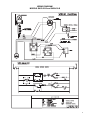
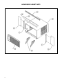
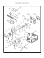
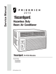
1
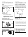
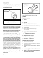
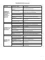
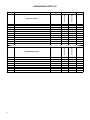
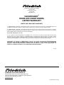
2007 Service & Parts Manual
Room Air Conditioners
60 Hz Models
SH15L30-B
SH20L30-B
HG-SVC-PRTS-07 (3-07)
TABLE OF CONTENTS
Specifications ......................................................................................................................................................... 3
Performance Data .................................................................................................................................................. 3
Component Operation & Testing ........................................................................................................................... 4
Compressors .......................................................................................................................................................... 4
Thermal Overload ................................................................................................................................................. 4
Checking Compressor Efficiency........................................................................................................................... 4
Fan Motor ............................................................................................................................................................... 5
Solid State Relay .................................................................................................................................................... 5
System Control Switch .......................................................................................................................................... 5
Run Capacitor ........................................................................................................................................................ 5
Thermostat ............................................................................................................................................................. 5
Low Ambient Bypass Valve.................................................................................................................................... 6
Sealed Refrigeration System Repairs.................................................................................................................... 6
Hermetic Component Replacement ...................................................................................................................... 7
Special Procedure in the case of Compressor Motor Burn-Out .......................................................................... 7
Rotary Compressor Special Troubleshooting & Service ...................................................................................... 7
Refrigerant Charge................................................................................................................................................. 7
Troubleshooting ................................................................................................................................................ 8-10
Wiring Diagram .................................................................................................................................................... 11
Cabinet Parts Diagram........................................................................................................................................ 12
Chassis Parts Diagram ....................................................................................................................................... 13
Parts List ......................................................................................................................................................... 14-15
Warranty ............................................................................................................................................................... 16
2
3
46
SH20L30-B
34
26
19800/19500
17 15/16
25 15/16
25
230/208
10.0/10.9
7.9/8.7
Amps
AHAM
27 3/8
27
3/8
9 3/16
9
3/16
Depth
Hood to
Louvers
3 1/16
3
1/16
Minimum
Extension
Into
Room
Dimensions (Inches)
230/208
Depth
Overall
125
206
16 15/16
16
15/16
Minimum
Extension
Outside
2200/2167
1765/1765
Watts
196
129
27 7/8
27
7/8
Min.
42
42
Max.
Window Width
(Inches)
9.0/9.0
8.5/8.5
EER
MAXIMUM TEMPERATURE RATING FOR CLASS I, DIVISION 2, GROUPS A,B,C,D
18 3/16
16
3/16
26
250V - 15A
250V - 15A
Volts - Amps
Circuit Rating
Breaker or
T - D Fuse
8-way
8-way
10.1
8.2
166
140
Net
179
152
Shipping
Weight
(Lbs.)
375
375
CFM
Room Side Air
Circulation
271
258
Discharge
Amps
Cool
-
-
Amps
Heat
-
-
Locked
Rotor
Amps
ELECTRICAL RATINGS
OPERATING TEMPERATURE CODE T3B
26 3/16
3/16
Width
75
76
Suction
OPERATING
PRESSURES
Air Direction
Controls
28
98
SubCooling
Thru-The-Wall
Finished Hole
(Inches)
5.7
4.0
(Pints/ Hr.)
Moisture
Removal
8
16
Super
Heat
Height
97
108
Liquid
Temp
Energy
Efficiency
Ratio AHAM
52
61
Due to continuing engineering research and technology, specifications are subject to change without notice.
Manufactured under U.S. Design Patent DES 368, 306 decorative front; Utility Patent 5, 622, 058
MAXIMUM outdoor ambient operating temperature is 130°F (54°C).
15
15/16
15/16
SH15L30
Width
Height
SH20L30
Model
46
56
CONDENSER
Discharge Suction
TEMP.
Temp
Temp
DEG. F
Electrical Characteristics (60 Hertz)
46
52
Volts Rated
Installation Information
15000/15000
SH20L30
(BTU/Hr.- AHAM)
SH15L30
Model
Cooling Capacity
Product Specifications
54
SH15L30-B
60 Hz Models
E(out)
E(in)
Discharge
Air
Temp.
Drop F.
EVAPORATOR
TEMP. DEG. F
EVAPORATOR AIR
TEMP. DEG. F
Performance Data: Cooling
39.0
28.5
Charge
in OZ.
R-22
REF.
357
363
Evap
CFM
1100
1100
Motor
RPM
20
15
60 Hertz
Amps
BREAKER
FUSE
COMPONENT OPERATION AND TESTING
WARNING
DISCONNECT ELECTRICAL POWER TO THE
UNIT BEFORE SERVICING OR TESTING
Testing Procedures
1.
Terminal "C" and "S" – no continuity – open winding
– replace compressor.
2.
Terminal "C" and "R" – no continuity – open winding
– replace compressor.
3.
Terminal "R" and "S" – no continuity – open winding
- replace compressor.
4.
Terminal "C" and the shell of the compressor – continuity
– grounded motor – replace compressor.
5.
Should continuity exist between terminals "R" and "S",
but not between terminals "C" and "S" and "C" and "R",
the internal overload may be open. If the compressor is
extremely hot, allow it sufficient time to cool. It may require
as long as one hour for the compressor to cool sufficiently
for the internal overload to close.
COMPRESSORS
Compressors are single phase, 208/230 volt. All compressor
motors are permanent split capacitor type, using only a running
capacitor across the start and run terminal.
All compressors are internally spring mounted and externally
mounted on rubber isolators.
Line Voltage Overload
The compressor is equipped with an internal line voltage overload. This overload is embedded in the windings of the motor
to sense the motor temperature. The overload will open and
disconnect the power to the motor due to high temperatures
caused by:
1.
A locked rotor.
2.
Excessive running amps.
3.
High discharge temperature.
4.
Low refrigerant charge.
GROUND TEST
Use an ohmmeter set on its highest scale. Touch one lead to
the compressor body (clean point of contact, as a good connection is a must) and the other probe in turn to each compressor
terminal. (See Figure 3.) If a reading is obtained, the compressor
is grounded and must be replaced.
FIGURE 3 TYPICAL GROUND TEST
FIGURE 1 INTERNAL OVERLOAD
LINE BREAK
INTERNAL OVERLOAD
OHMMETER
CHECKING COMPRESSOR EFFICIENCY
COMPRESSOR WINDING TEST (Figure 2.)
Remove the compressor terminal box cover and disconnect the
wires from the terminals. Using an ohmmeter, check continuity
across the following:
FIGURE 2 COMPRESSOR WINDING TEST
The reason for compressor inefficiency is normally due to broken or damaged suction and/or discharge valves, reducing the
ability of the compressor to pump refrigerant gas.
This condition can be checked as follows:
1. Install a piercing valve on the suction and discharge or liquid
process tube.
2. Attach gages to the high and low sides of the system.
3. Start the system. Run a "cooling or heating performance test."
If test shows:
A. Below normal high side pressure.
B. Above normal low side pressure.
C. Low temperature difference across the coil.
The compressor valves are faulty - replace the compressor.
4
FAN MOTOR (Figure 4)
CAPACITOR, RUN
A 230 volt single phase permanent split capacitor motor is
used to drive the evaporator blower and condenser fan. A
running capacitor is wired across the start and run terminals
of the motor.
A run capacitor is wired across the auxiliary and main winding
of a single phase permanent split capacitor motor such as the
compressor and fan motors. A single capacitor can be used for
each motor or a dual rated capacitor can be used for both.
The motor is totally enclosed and is protected with a line voltage overload located internally of the motor. The motor shaft
is stainless steel to resist corrosion.
The capacitor’s primary function is to reduce the line current
while greatly improving the torque characteristics of a motor.
The capacitor also reduces the line current to the motor by
improving the power factor of the load. The line side of the
capacitor is marked with a red dot and is wired to the line side
of the circuit (see Figure 7.)
FIGURE 4
FAN MOTOR
FIGURE 7 RUN CAPACITOR HOOK–UP
COMPRESSOR
FAN
MOTOR
FAN MOTOR – TEST
Disconnect power to the unit.
1. Determine that the capacitor is serviceable.
RED DOT
2. Disconnect the black lead from the circuit board.
3. Apply "live" test cord leads to the common terminal of
the capacitor and the black lead. The motor should run
at high speed.
RUN CAPACITOR
SOLID STATE RELAY (Figure 5)
CAPACITOR – TEST
Two 50 amp rated 208/230 volt solid state relays are used to
energize the compressor and fan motor. Terminals 3 and 4 are the
208/230 volt line side. Terminals 1 and 2 are load side contacts.
1.
Remove the capacitor from the unit.
2.
Check for visual damage such as bulges, cracks, or
leaks.
3.
For dual rated capacitors, apply an ohmmeter lead to
the common (C) terminal and the other probe to the
compressor (HERM) terminal. A satisfactory capacitor will
cause a deflection on the pointer, then gradually move back
to infinity.
4.
Reverse the leads of the probe and momentarily touch the
capacitor terminals. The deflection of the pointer should be
two times that of the first check if the capacitor is good.
FIGURE 5
SOLID STATE
RELAY
Line side
Load side
LED indicates
contacts closed
when lit
5. Repeat steps 3 and 4 to check the fan motor capacitor.
SYSTEM CONTROL SWITCH (Figure 6)
This switch is double pole, single throw. Check for continuity
between terminals 2 and 3, and 5 and 6.
FIGURE 6
SWITCH, ON-OFF
NOTE: A shorted capacitor will indicate a low
resistance and the pointer will move more to the “0”
end of the scale and remain there as long as the
probes are connected. An open capacitor will show
no movement of the pointer when placed across the
terminals of the capacitor.
5
THERMOSTAT
FIGURE 9
LOW AMBIENT
Bypass VALVE
A cross ambient thermostat is used to maintain the desired
comfort level. The thermostat reacts only to a change in
temperature at the bulb location. Important to the successful
operation of the unit is the position of the sensing bulb in relation
to the evaporator (see Figure 8).
FIGURE 8
SENSING
BULB LOCATION
SEALED REFRIGERATION SYSTEM
REPAIRS
Equipment Required:
1.
Voltmeter
RANGE: Thermostat
2.
Ammeter
(Part No. 618-225-02)
60° F ( ± 2° ) to 90° F( ± 4° )
3.
Ohmmeter
4.
E.P.A Approved Refrigerant Recovery System
TEST
Remove the wires from the thermostat. Turn the thermostat to
its coldest position. Check to see if there is continuity between
the two terminals. Turn the thermostat to its warmest position.
Check continuity to see if the thermostat contacts open.
Note: The temperature must be within the range listed to check
the thermostat. Refer to the troubleshooting section in this
manual for additional information on thermostat testing.
LOW AMBIENT BYPASS VALVE (Figure 9)
The HazardGard unit is designed to operate at low outside
ambient temperatures. This is accomplished by the use of a
bypass valve installed in the refrigeration circuit. The valve
is connected between the discharge line at the compressor
and the suction process tube. The valve responds to suction
pressure which, when reduced in the system, causes the
valve to open and bypass hot gas from the high pressure side
to the low pressure side of the system. The hot gas entering
the compressor mixes with the cool gas returned through the
suction line, thus increasing the suction pressure. The valve
is preset to open when the suction pressure reaches 50 psig.
This pressure setting cannot be altered. The system can be
operated at outdoor temperatures as low as 45° F before the
evaporator coil will begin to accumulate frost.
To determine if the valve operates, block the return air to the
evaporator coil. Turn on the unit and touch the tube at the
bypass valve outlet which connects to the suction process
tube. When the low side pressure reaches approximately 50
psig, the valve will begin to open and the tube will get hot. This
method will determine if the valve is responding to the suction
pressure change.
6
5. Vacuum Pump (capable of 200 microns or less vacuum).
6. Acetylene Welder
7.
Electronic Halogen Leak Detector (G.E. Type
H-6 or equivalent).
8. Accurate refrigerant charge measuring device
such as:
a. Balance Scales - 1/2 oz. accuracy
b. Charging Board - 1/2 oz. accuracy
9.
High Pressure Gauge - (0-400 lbs.)
10. Low Pressure Gauge - (30" - 150 lbs.)
11. Vacuum Gauge - (0-1000 microns)
Equipment Must Be Capable of:
1.
Recovering CFC’s as low as 5%.
2.
Evacuation from both the high side and low side of the
system simultaneously.
3.
Introducing refrigerant charge into the high side of the
system.
4.
Accurately weighing the refrigerant charge actually introduced into the system.
5.
Facilities for flowing nitrogen through the refrigeration
tubing during all brazing processes.
HERMETIC COMPONENT REPLACEMENT
The following procedure applies when replacing components
in the sealed refrigeration circuit or repairing refrigerant leaks.
(Compressor, condenser, evaporator, capillary tube, refrigerant
leaks, etc.)
1.
Recover the refrigerant from the system at the process
tube located on the high side of the system by installing
a line tap on the process tube. Apply the gauge from the
process tube to EPA approved gauges from the process
tube to the EPA approved recovery system. Recover the
CFC’s in the system to at least 5%.
2.
Cut the process tube below the pinch off in the suction side
of the compressor.
3.
Connect the line from the nitrogen tank to the suction
process tube.
4.
Drift dry nitrogen through the system and unsolder the
more distant connection first. (Filter drier, high side
process tube, etc.)
5. Replace the inoperative component, and always install a
new filter drier. Drift dry nitrogen through the system when
making these connections.
12. Restart the unit several times after allowing pressures
to stabilize. Pinch off the process tubes, cut and solder
the ends. Remove the pinch off tool, and leak check the
process tube ends.
SPECIAL PROCEDURES IN THE CASE OF
COMPRESSOR MOTOR BURNOUT
1.
Recover all refrigerant and oil from the system.
2.
Remove the compressor, capillary tube and filter drier from
the system.
3.
Flush the evaporator, condenser and all connecting tubing
with dry nitrogen, or equivalent, to remove all contamination
from the system. Inspect the suction and discharge lines
for carbon deposits. Remove and clean if necessary.
4.
Reassemble the system, including a new drier-strainer and
capillary tube.
5. Proceed with processing as outlined under hermetic
component replacement.
ROTARY COMPRESSOR
SPECIAL TROUBLESHOOTING & SERVICE
6. Pressurize the system to 30 PSIG with proper refrigerant
and boost the refrigerant pressure to 150 PSIG with dry
nitrogen.
Basically, troubleshooting and servicing rotary compressors
is the same as on the reciprocating compressor with only a
few exceptions.
7.
1.
Because of the spinning motion of the rotary, the mounts
are critical. If vibration is present, check the mounts
carefully.
2.
The electrical terminals on the rotary are in a different order
than the reciprocating compressors. The terminal markings
are on the cover gasket. Use your wiring diagram to insure
the correct connections.
Leak test the complete system with the electric halogen
leak detector, correcting any leaks found.
8. Reduce the system to zero gauge pressure.
9.
Connect the vacuum pump to the high side and low side
of the system with deep vacuum hoses, or copper tubing.
(Do not use regular hoses.)
10. Evacuate the system to an absolute holding pressure of
200 microns or less.
NOTE: This procedure can be sped up by the use of
heat lamps, or by breaking the vacuum with refrigerant
or dry nitrogen at 5,000 microns. Pressure system to 5
PSIG and leave in the system a minimum of 10 minutes.
Recover refrigerant, and proceed with evacuation to a
pressure of 200 microns or a minimum of 10%.
11. Break the vacuum by charging the system from the high
side with the correct amount of refrigerant specified. This
will prevent boiling the oil out of the crankcase.
NOTE: If the entire charge will not enter the high side,
allow the remainder to enter the low side in small
increments while operating the unit.
REFRIGERANT CHARGE
1. The refrigerant charge is extremely critical. Measure the
charge carefully and as exactly as possible to the nameplate
charge.
2. The correct method for charging the rotary is to introduce
liquid refrigerant into the high side of the system with the
unit off. Then start the compressor and enter the balance
of the charge, gas only, into the low side.
The introduction of liquid into the low side, without the use of
a capillary tube, will cause damage to the discharge valve
of the rotary compressor.
NOTE: All inoperative compressors returned to Friedrich
must have all lines properly plugged with the plugs from
the replacement compressor.
7
TROUBLESHOOTING
PROBLEM
POSSIBLE CAUSE
TO CORRECT
Power disconnected.
Check power source.
System switch in “Off” position. Set switch correctly.
UNIT DOES NOT RUN.
EVAPORATOR COIL
FREEZES UP.
Branch circuit fuse blown or
circuit breaker tripped.
Replace fuse, reset breaker. If repeats, check fuse or breaker
size. Check for shorts in unit wiring and components.
Inoperative system switch.
Test for continuity.
Loose or disconnected wiring
at switch.
Check wiring and connections.
Connect per wiring diagram.
Inoperative switch (On-Off).
Test for continuity, 3 and 2, 5 and 6.
Dirty Filter.
Clean as recommended in Owner’s Manual.
Restricted air flow.
Check for dirty or obstructed coil - clean as required.
Inoperative thermostat.
Test for shorted thermostat or stuck contacts.
Short of refrigerant.
De-ice coil and check for leak.
Partially restricted capillary.
De-ice coil. Check temperature differential across coil. Touch
test coil return bends for same temperature. Test for low
running current.
Inoperative fan motor.
Test and replace if inoperative.
Excessive heat load.
Test cooling performance of unit. Unit undersized.
Restriction in line.
Check for partially iced coil. Check temperature split across
coil.
Refrigerant leak.
Check for presence of oil on silver soldered connections.
Check for partially iced coil. Check split across coil. Check for
low running amperage.
Thermostat contacts stuck.
Check operation of thermostat. Replace if contacts remain
closed.
Loss of charge in thermostat
bulb.
Place jumper across thermostat terminals. If unit operates,
replace thermostat.
Loose or broken parts in
thermostat.
Check as above.
COMPRESSOR RUNS
CONTINUALLY.
DOES NOT CYCLE OFF.
THERMOSTAT DOES
NOT TURN UNIT ON.
Incorrect wiring.
Connect per wiring diagram.
System switch open.
Test for continuity at switch terminals 2 and 3.
Thermostat set at coldest point Turn to highest temperature setting to see of unit will cycle off.
THERMOSTAT DOES
NOT TURN UNIT OFF.
8
Thermostat contacts stuck.
Disconnect power to the unit. Remove cover of thermostat
and check if contact is stuck, if so replace thermostat.
Switch (On - Off) shorted.
Test switch for open contacts at terminals 2 and 3 with switch
in “Off” position.
TROUBLESHOOTING (Continued)
PROBLEM
POSSIBLE CAUSE
TO CORRECT
Compressor attempts to start
before system pressures are
equalized.
Allow a minimum of two (2) minutes to allow pressures to
equalize before attempting to start.
COMPRESSOR
ATTEMPTS TO
START, OR RUNS
FOR SHORT
PERIODS ONLY.
Low or fluctuating voltage.
Check voltage with unit operating. Check for other
appliances on the circuit. Unit should be on separate circuit
for proper voltage, and be fused separately.
Incorrect wiring.
Connect per wiring diagram.
Shorted or incorrect capacitor.
Check by substituting a known good capacitor of correct
rating.
CYCLES ON
OVERLOAD.
Restricted or low air flow through
condenser coil.
Check for proper fan speed or blocked condenser.
Compressor running abnormally
hot.
Check for kinked discharge line or restricted condenser.
Check amperage.
Overload opens too soon.
Change compressor if all other corrections above are
normal.
Thermostat contacts not closing.
Check continuity of thermostat at coldest setting. Jump
contacts, if compressor runs, replace thermostat.
Low voltage supply.
Check for nameplate voltage.
Switch (On-Off) inoperative.
Test for continuity.
COMPRESSOR DOES
Open capacitor.
NOT START - FAN
MOTOR RUNS.
Internal overload open.
DOES NOT COOL,
OR COOLS ONLY
SLIGHTLY.
Check by substituting a known good capacitor of correct
rating.
Check voltage at compressor terminals. If voltage is
satisfactory, replace compressor.
Relay open
Replace relay
Open or shorted compressor
windings
Check windings for continuity and resistance. Direct test
compressor. If direct test fails, replace compressor.
Thermostat open or inoperative.
Set to coldest position. Test thermostat and replace if
necessary.
Dirty air filter.
Clean as recommended in Owner’s Manual.
Dirty or plugged condenser or
evaporator coil.
Use steam or detergents to clean.
Poor air circulation in area being
cooled.
Adjust air louvers.
Low capacity - undercharge.
Clean, check for leak and make repair.
Check amperage draw against nameplate. If not conclusive,
Compressor not pumping properly.
make pressure test.
9
TROUBLESHOOTING (Continued)
PROBLEM
FAN MOTOR DOES
NOT RUN.
SWITCH (ON-OFF)
DOES NOT CUT
FAN MOTOR OFF.
NOISY AND/OR
VIBRATION.
WATER LEAKS
INTO ROOM.
OUTSIDE WATER
LEAKS.
10
POSSIBLE CAUSE
TO CORRECT
Defective switch (On-Off).
Check continuity across terminals 2 and 3.
Fan capacitor open.
Check by substituting a known good capacitor of the same
rating.
Inoperative fan motor.
Direct test fan motor.
Incorrect wiring of fan circuit.
Connect per wiring diagram.
Relay open.
Replace Relay.
Check for seized motor bearings.
Rotate by hand, add oil, if noisy, replace.
Bound fan blade or blower wheel.
Adjust for proper clearance.
Selector Switch Relay
Replace selector switch. Replace relay.
Poor installation.
Refer to Installation Instructions for proper installation.
Fan blade striking chassis.
Adjust motor mount to attain proper fan blade and blower
wheel clearance.
Compressor vibrating.
Check for deteriorated compressor grommets, or missing
mounting parts.
Loose cabinet parts, improperly
mounted components, tubing
rubbing.
Adjust and tighten as required.
Evaporator drain pan overflowing.
Clean obstructed drain trough.
Condensation forming on bottom
of base pan.
Evaporator drain pan broken or cracked. Reseal or
replace.
Water dripping from discharge air
grilles.
Dirty evaporator coil, or extremely high humidity conditions.
Clean coil with steam or detergent.
Evaporator drain pan cracked or
obstructed.
Repair and clean, or replace as required.
Water in center section of base
pan (compressor area).
Remove condenser shroud, Clean and remove old sealer
from base pan and shroud. Apply new sealer, reinstall and
check.
Dirty Condenser coil.
Clean with steam or detergent.
Fan blade and slinger ring
improperly positioned.
Adjust fan blade to 1/2" clearance from condenser coil.
WIRING DIAGRAM
MODELS SH15L30-B and SH20L30-B
11
HAZARDGARD CABINET PARTS
12
HAZARDGARD CHASSIS PARTS
13
HAZARDGARD PARTS LIST
PART NO#
ELECTRICAL PARTS
1
COMPRESSOR
61193549
1
COMPRESSOR
61193550
2
MOTOR, FAN
61871426
2
MOTOR, FAN
61871427
CODE
1
600
1
600
1
110
1
110
5
SWITCH, ON-OFF DPST
60935300
1
1
130
*
INSULATOR, ELECTRICAL
61829700
1
1
399
*
RELAY, SOLID STATE
61108800
2
2
399
6
THERMOSTAT
61822502
1
1
120
1
61080546
61080547
*
HARNESS, WIRE, COMP.
61821308
9
EVAPORATOR COIL
61850100
9
EVAPORATOR COIL
61850001
10
CONDENSER COIL
62050410
10
CONDENSER COIL
62050411
150
1
150
1
1
399
SH20L30-B
CAPACITOR 20/7.5 440 V.
CAPACITOR 25/7.5 440 V
SH15L30-B
7
7
REFRIGERATION PARTS
14
MODELS
SH20L30-B
DESCRIPTION
SH15L30-B
REF
1
400
1
1
*
DRIER, LIQUID
60308101
1
*
CAPILLARY TUBE
01390005
1
*
CAPILLARY TUBE
03760518
*
VALVE, BY-PASS
60809500
2
400
410
1
410
1
480
2
471
471
520
HAZARDGARD PARTS LIST
PART NO#
MODELS
CHASSIS PARTS
CODE
SH20L30-B
DESCRIPTION
SH15L30-B
REF
8
HOLDER, THERMOSTAT
61829800
1
1
999
11
KNOB, CONTROL
61493915
1
1
761
17
DECORATIVE PANEL
61822662
1
1
760
22
FAN BLADE, COND.
60542003
1
22
FAN BLADE, COND.
60542004
1
710
23
BLOWER WHEEL, EVAP.
60610616
23
BLOWER WHEEL, EVAP.
60610617
1
700
25
FAN MOTOR MOUNT
61802500
25
FAN MOTOR MOUNT
61804100
1
900
26
SHROUD, CONDENSER
61803601
26
SHROUD, CONDENSER
61804901
1
720
27
BRACE, COND.SHROUD
61802600
3
3
722
29
BLOWER FRONT
61817300
1
29
BLOWER FRONT
61817400
1
742
30
SCROLL
61814905
30
SCROLL
61817505
1
743
32
BASE PAN
61803444
1
1
730
34
BOLT, COMP. MOUNT
91400400
3
3
791
35
PLENUM ASSEMBLY
61831006
1
1
753
36
OUTER SHELL
61825708
1
36
OUTER SHELL
61825709
1
770
37
GRILLE, INTAKE
61808906
37
GRILLE, INTAKE
61811111
38
WINGBOARD
60294415
38
WINGBOARD
60294420
40
ANGLE, WINGBOARD TOP
61819711
41
ANGLE,WINGBORD SIDE
61819811
LATCH, INTAKE GRILLE
*
710
1
700
1
900
1
720
742
1
743
770
1
772
1
1
772
999
1
999
1
1
999
2
2
999
61989000
2
2
752
1
1
754
*
FILTER, AIR
60865808
*
FILTER, AIR
60865809
754
*
HOLDER, FILTER
61823000
2
2
756
*
DRAIN PAN, EVAP.
61803800
1
1
840
3
790
1
771
*
GROMMET, COMP. MOUNT
01193549
3
*
REAR GRILLE
61818500
1
*
REAR GRILLE
61818501
771
*
BAG, ASSY. HARDWARE
60846016
1
1
999
*
GASKET, CHASSIS
61717301
1
1
780
OPTIONAL ACCESSORY ITEMS
*
DRAIN KIT, DC-2
01900235
1
1
*
START KIT, CAP.\RELAY
01900312
1
1
15
Friedrich Air Conditioning Company
P.O. Box 1540
San Antonio, TX 78295
210.357.4400
www.friedrich.com
HAZARDGARD®
ROOM AIR CONDITIONERS
LIMITED WARRANTY
LIMITED ONE YEAR PARTS WARRANTY
1. Limited warranty – One year. Friedrich warrants that it will provide a replacement for any part of this HazardGard Room Air
Conditioner found defective in material or workmanship for a period of one (1) year from the date of original purchase.
2. Limited warranty – One year. The Friedrich warranty also covers the cost of labor for repairing any compressor, condenser,
evaporator or inter-connecting tubing found defective within the warranty period, providing the unit is returned to an authorized
Friedrich Repair Station located within the Continental United States.
The Friedrich warranty does not cover:
(1) Any charges for removal, transportation or reinstallation of the unit; (2) the cost of labor to replace parts other than those
described above; and (3) does not apply to any HazardGard Room Air Conditioner that has been subject to (a) accident, misuse,
flood, fire, or neglect; (b) repairs or alterations outside of the Friedrich Authorized Dealer or Service Center so as to affect adversely
its performance and reliability; or (c) any repairs or servicing as a result of using parts not sold or approved by Friedrich.
LIMITATIONS: This warranty is a LIMITED warranty. Anything in the warranty notwithstanding, IMPLIED WARRANTIES
FOR PARTICULAR PURPOSE AND MERCHANTABILITY SHALL BE LIMITED TO THE DURATION OF THE EXPRESS
WARRANTY. MANUFACTURER EXPRESSLY DISCLAIMS AND EXCLUDES ANY LIABILITY FOR CONSEQUENTIAL OR
INCIDENTAL DAMAGES FOR BREACH OF ANY EXPRESSED OR IMPLIED WARRANTY.
(10-04)
FRIEDRICH AIR CONDITIONING CO.
Post Office Box 1540 · San Antonio, Texas 78295-1540
4200 N. Pan Am Expressway · San Antonio, Texas 78218-5212
(210) 357-4400 · FAX (210) 357-4480
www.friedrich.com
Printed in the U.S.A.
HG-SVC-PRTS-07 (3-07)