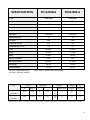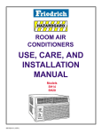
1
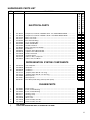
2002
HAZARDGARD®
ROOM AIR CONDITIONER
Models
SH14J30B-A
SH20J30B-A
Service & Parts
Manual
AMERICA’S BEST AIR CONDITIONER
HG2002 (02/02)
TABLE OF CONTENTS
PAGE
Specifications ....................................................................................................................
Performance Data.............................................................................................................
Component Operation & Testing .......................................................................................
Compressors ....................................................................................................................
Thermal Overload .............................................................................................................
Checking Compressor Efficiency ......................................................................................
Fan Motor .........................................................................................................................
System Control Switch ......................................................................................................
Run Capacitor ...................................................................................................................
Thermostat ........................................................................................................................
Low Ambient By-Pass Valve ..............................................................................................
Sealed Refrigeration System Repairs ...............................................................................
Hermetic Component Replacement ..................................................................................
Special Procedure in the case of Compressor Motor Burn-Out ........................................
Rotary Compressor Special Troubleshooting & Service ...................................................
Refrigerant Charge ...........................................................................................................
3
3
4
4
4
5
5
5
6
6
8
8
9
9
10
10
TROUBLESHOOTING
Troubleshooting SH14J30B-A ........................................................................................... 11
Troubleshooting SH20J30B-A ........................................................................................... 16
WIRING DIAGRAM
SH14J30B-A / SH20J30B-A ............................................................................................. 14
PARTS LIST
SH14J30B-A / SH20J30B-A Model Chassis Parts List ...................................................... 18
SH20J30B-A / SH20J30B-A Model Cabinet Parts List ...................................................... 19
2
SH14J30B-A
SH20J30B-A
14000/14000
19000/18800
E.E.R. - Btu/watt
8.0/8.0
8.5/8.5
Volts
230/208
230/208
60/1
60/1
7.8/8.5
9.9/10.8
1750/1750
2235/2210
15
20
Fan RPM
1095
1095
Evaporator Air CFM
375
425
Dehumidification-Pts./hr.
4.0
5.7
Width
25-15/16”
25-15/16”
Height
15-15/16”
17-15/16”
Depth
27-3/8”
27-3/8”
Min. Ext. into Room
5-7/8”
5-7/8”
Min. Ext to Outside
16-15/16”
16-15/16”
Net Weight
129 Lbs.
177 Lbs.
Shipping Weight
147 Lbs.
199 Lbs.
SPECIFICATIONS
BTUH
Hertz/Phase
Amperes
Total Watts
Fuse/Breaker Size
Maximum Temperature Rating
for Class 1, Division 2, Group D
PERFORMANCE
DATA *
SH14J30B-A
120 0 C (2480 F) Ignition Temperature Rating
EVAPORATOR AIR
TEMP° F
OPERATING
PRESSURES
ELECTRICAL
RATINGS
SH20J30B-A
COMP.
OIL
DISCHARGE
AIR
TEMP
DROP °F
SUCTION
DISCHARGE
AMPS
LOCKED
ROTOR AMPS
CHARGE IN
OUNCES
CHARGE IN
FLUID OZ.
56.78
23.22
79
296
7.8
8.5
43
28
32
52.83
27.16
79.5
282
9.8
10.4
52
39
32
SH14J30B-A
SH20J30B-A
R-22
REFRIG.
* Rating Conditions: 80° F. Room Air Temperature and 59% Relative Humidity with 95° F. Outside Air Temperature at 40% Relative Humidity.
3
COMPONENT OPERATION AND TESTING
WARNING
DISCONNECT ELECTRICAL POWER TO
THE UNIT BEFORE SERVICING OR
TESTING
COMPRESSORS
COMPRESSOR WINDING TEST
(See Figure 2.)
Remove the compressor terminal box cover and
disconnect the wires from the terminals. Using
an ohmmeter, check continuity across the
following:
FIGURE 2 COMPRESSOR WINDING TEST
Compressors are single phase, 208/230 volt. All
compressor motors are permanent split capacitor
type, using only a running capacitor across the
start and run terminal.
All compressors are internally spring mounted and
externally mounted on rubber isolators.
Line Voltage Overload
Testing Procedures
The compressor is equipped with an internal line
voltage overload. This overload is embedded in
the windings of the motor to sense the motor
temperature. The overload will open and
disconnect the power to the motor due to high
temperatures caused by:
2. Terminal "C" and "R" - no continuity open winding - replace compressor.
3. Terminal "R" and "S" - no continuity
open winding - replace compressor.
1.
A locked rotor.
2.
Excessive running amps.
3.
High discharge temperature.
4.
Low refrigerant charge.
FIGURE 1 INTERNAL OVERLOAD
LINE BREAK
INTERNAL OVERLOAD
OHMMETER
4
1. Terminal "C" and "S" - no continuity open winding - replace compressor.
4. Terminal "C" and the shell of the
compressor – continuity – grounded
motor – replace compressor.
5. Should continuity exist between
terminals "R" and "S", but not between
terminals "C" and "S" and "C" and "R",
the internal overload may be open. If
the compressor is extremely hot, allow
it sufficient time to cool. It may require
as long as one hour for the compressor
to cool sufficiently for the internal
overload to close.
GROUND TEST
FAN MOTOR (Figure 4)
Use an ohmmeter set on its highest scale. Touch
one lead to the compressor body (clean point of
contact, as a good connection is a must) and the
other probe in turn to each compressor terminal.
(See Figure 3.) If a reading is obtained, the
compressor is grounded and must be replaced.
A 230 volt single phase permanent split capacitor
motor is used to drive the evaporator blower and
condenser fan. A running capacitor is wired
across the start and run terminals of the motor.
The motor is totally enclosed and is protected with
a line voltage overload located internally of the
motor. The motor shaft is stainless steel to resist
corrosion.
FIGURE 3 TYPICAL GROUND TEST
FIGURE 4 FAN MOTOR
CHECKING COMPRESSOR EFFICIENCY
The reason for compressor inefficiency is
normally due to broken or damaged suction
and/or discharge valves, reducing the ability of
the compressor to pump refrigerant gas.
This condition can be checked as
follows:
1. Install a piercing valve on the suction and
discharge or liquid process tube.
FAN MOTOR – TEST
Disconnect power to the unit.
1. Determine that the capacitor is serviceable.
2. Disconnect the black lead from the circuit
board.
3. Apply "live" test cord leads to the common
terminal of the capacitor and the black lead.
The motor should run at high speed.
2. Attach gages to the high and low sides of the
system.
3. Start the system and run a "cooling or
heating performance test."
If test shows:
A. Below normal high side pressure.
B. Above normal low side pressure.
C. Low temperature difference across the coil.
The compressor valves are faulty replace the compressor.
5
SYSTEM CONTROL SWITCH
CAPACITOR – TEST
(Figure 5)
This switch is double pole, single throw. Check 1. Remove the capacitor from the unit.
for continuity between terminals 2 and 3, and 5 2. Check for visual damage such as bulges,
and 6.
cracks, or leaks.
3. For dual rated capacitors, apply an ohmmeter
lead to the common (C) terminal and the other
probe to the compressor (HERM) terminal.
A satisfactory capacitor will cause a deflection
on the pointer, then gradually move back to
infinity.
FIGURE 5 SWITCH, ON-OFF
4. Reverse the leads of the probe and
momentarily touch the capacitor terminals.
The deflection of the pointer should be two
times that of the first check if the capacitor is
good.
CAPACITOR, RUN
5. Repeat steps 3 and 4 to check the fan motor
capacitor.
A run capacitor is wired across the auxiliary and
main winding of a single phase permanent split
capacitor motor such as the compressor and fan
motors. A single capacitor can be used for each
motor or a dual rated capacitor can be used for
both.
The capacitor’s primary function is to reduce the
line current while greatly improving the torque
characteristics of a motor. The capacitor also
reduces the line current to the motor by improving
the power factor of the load. The line side of the
capacitor is marked with a red dot and is wired to
the line side of the circuit. (See Figure 6.)
FIGURE 6
RUN CAPACITOR HOOK–UP
COMPRESSOR
FAN
MOTOR
RED DOT
RUN CAPACITOR
6
NOTE: A shorted capacitor will indicate a low
resistance and the pointer will move more
to the “0” end of the scale and remain there
as long as the probes are connected. An
open capacitor will show no movement of
the pointer when placed across the terminals
of the capacitor.
THERMOSTAT
A cross ambient
thermostat is used
to maintain the desired
comfort level. The
thermostat reacts only to
a change in temperature
at the bulb location.
Important to the
successful operation
of the unit is the position
of the sensing bulb in
relation to the evaporator.
See Figure 7.
FIGURE 7
SENSING BULB
LOCATION
RANGE:
Thermostat
(Part No. 618-225-02)
60° F ( ± 2° ) to 90° F( ± 4° )
TEST
Remove the wires from the thermostat. Turn the
thermostat to its coldest position. Check to see
if there is continuity between the two terminals.
Turn the thermostat to its warmest position.
Check continuity to see if the thermostat contacts
open.
Note: The temperature must be within the
range listed to check the thermostat. Refer to
the troubleshooting section in this manual for
additional information on thermostat testing.
(More Follows)
7
LOW AMBIENT BY–PASS VALVE
The HazardGard unit is designed to operate at
low outside ambient temperatures. This is
accomplished by the use of a bypass valve
installed in the refrigeration circuit. The valve is
connected between the discharge line at the
compressor and the suction process tube. The
valve responds to suction pressure which, when
reduced in the system, causes the valve to open
and bypass hot gas from the high pressure side
to the low pressure side of the system. The hot
gas entering the compressor mixes with the cool
gas returned through the suction line, thus
increasing the suction pressure. The valve is
preset to open when the suction pressure reaches
50 psig. This pressure setting cannot be altered.
The system can be operated at outdoor
temperatures as low as 45° F before the
evaporator coil will begin to accumulate frost.
SEALED REFRIGERATION SYSTEM
REPAIRS
EQUIPMENT REQUIRED
1. Voltmeter
2. Ammeter
3. Ohmmeter
4. E.P.A Approved Refrigerant Recovery System
5. Vacuum Pump (capable of 200 microns or
less vacuum).
6. Acetylene Welder
7. Electronic Halogen Leak Detector G.E. Type
H-6 or equivalent).
8. Accurate refrigerant charge measuring device
such as:
a. Balance Scales - 1/2 oz. accuracy
b. Charging Board - 1/2 oz. accuracy
9. High Pressure Gauge - (0-400 lbs.)
10. Low Pressure Gauge - (30" - 150 lbs.)
11. Vacuum Gauge - (0-1000 microns)
EQUIPMENT MUST BE CAPABLE OF:
To determine if the valve operates, block the return
air to the evaporator coil. Turn on the unit and 1. Recovering CFC’s as low as 5%.
touch the tube at the bypass valve outlet which
connects to the suction process tube. When the 2. Evacuation from both the high side and low
side of the system simultaneously.
low side pressure reaches approximately 50 psig,
the valve will begin to open and the tube will get
hot. This method will determine if the valve is 3. Introducing refrigerant charge into the high
side of the system.
responding to the suction pressure change.
4. Accurately weighing the refrigerant charge
actually introduced into the system.
FIGURE 8
LOW AMBIENT Bypass VALVE
8
5. Facilities for flowing nitrogen through the
refrigeration tubing during all brazing
processes.
HERMETIC COMPONENT REPLACEMENT
The following procedure applies when replacing
components in the sealed refrigeration circuit or
repairing refrigerant leaks. (Compressor,
condenser, evaporator, capillary tube, refrigerant
leaks, etc.)
10.Evacuate the system to an absolute holding
pressure of 200 microns or less.
NOTE: This procedure can be speeded up by
the use of heat lamps, or by breaking the
vacuum with refrigerant or dry nitrogen at
5,000 microns. Pressure system to 5 PSIG
and leave in the system a minimum of 10
minutes. Recover refrigerant, and proceed
with evacuation to a pressure of 200 microns
or a minimum of 10%.
1. Recover the refrigerant from the system at the
process tube located on the high side of the
system by installing a line tap on the process
tube. Apply the gauge from the process tube 11. Break the vacuum by charging the system
from the high side with the correct amount of
to EPA approved gauges from the process
refrigerant specified. This will prevent boiling
tube to the EPA approved recovery system.
the oil out of the crankcase.
Recover the CFC’s in the system to at least
5%.
NOTE: If the entire charge will not enter the
high side, allow the remainder to enter the
2. Cut the process tube below the pinch off in
low side in small increments while operating
the suction side of the compressor.
the unit.
3. Connect the line from the nitrogen tank to the 12.Restart the unit several times after allowing
pressures to stabilize. Pinch off the process
suction process tube.
tubes, cut and solder the ends. Remove the
pinch off tool, and leak check the process tube
4. Drift dry nitrogen through the system and
ends.
unsolder the more distant connection first.
(Filter drier, high side process tube, etc.)
SPECIAL PROCEDURES IN THE CASE OF
COMPRESSOR MOTOR BURNOUT
5. Replace the inoperative component, and
always install a new filter drier. Drift dry 1. Recover all refrigerant and oil from the system.
nitrogen through the system when making
2. Remove the compressor, capillary tube and
these connections.
filter drier from the system.
6. Pressurize the system to 30 PSIG with proper
refrigerant and boost the refrigerant pressure 3. Flush the evaporator, condenser and all
connecting tubing with dry nitrogen, or
to 150 PSIG with dry nitrogen.
equivalent, to remove all contamination from
the system. Inspect the suction and discharge
7. Leak test the complete system with the electric
lines for carbon deposits. Remove and clean
halogen leak detector, correcting any leaks
if necessary.
found.
4. Reassemble the system, including a new drierstrainer and capillary tube.
8. Reduce the system to zero gauge pressure.
9. Connect the vacuum pump to the high side 5. Proceed with processing as outlined under
hermetic component replacement.
and low side of the system with deep vacuum
hoses, or copper tubing. (Do not use regular
hoses.)
9
ROTARY COMPRESSOR SPECIAL
TROUBLESHOOTING AND SERVICE
REFRIGERANT CHARGE
Basically, troubleshooting and servicing rotary
compressors is the same as on the
reciprocating compressor with only a few
exceptions.
1. Because of the spinning motion of the rotary,
the mounts are critical. If vibration is present,
check the mounts carefully.
1. The refrigerant charge is extremely critical.
Measure the charge carefully and as exactly
as possible to the nameplate charge.
2. The correct method for charging the rotary is
to introduce liquid refrigerant into the high side
of the system with the unit off. Then start the
compressor and enter the balance of the
charge, gas only, into the low side.
2. The electrical terminals on the rotary are in a
different order than the reciprocating
compressors. The terminal markings are on
the cover gasket. Use your wiring diagram to
insure the correct connections.
The introduction of liquid into the low side,
without the use of a capillary tube, will cause
damage to the discharge valve of the rotary
compressor.
NOTE:
All inoperative compressors returned to
Friedrich must have all lines properly plugged
with the plugs from the replacement
compressor.
10
TROUBLESHOOTING
PROBLEM
Unit does not
run.
PROBLEM
Evaporator
coil freezes
up.
POSSIBLE CAUSE
Power disconnected.
System switch in “Off” position.
Branch circuit fuse blown or
circuit breaker tripped.
Inoperative system switch.
Loose or disconnected wiring at
switch.
Inoperative switch (On-Off).
POSSIBLE CAUSE
Dirty Filter.
Restricted air flow.
Inoperative thermostat.
Short of refrigerant.
Partially restricted capillary.
Inoperative fan motor.
PROBLEM
POSSIBLE CAUSE
Excessive heat load.
Restriction in line.
Compressor
runs
continually.
Does not
cycle off.
PROBLEM
Refrigerant leak.
Thermostat contacts stuck.
POSSIBLE CAUSE
Loss of charge in thermostat bulb.
Thermostat
does not turn
unit on.
PROBLEM
Thermostat
does not
turn unit off.
Loose or broken parts in
thermostat.
Incorrect wiring.
System switch open.
POSSIBLE CAUSE
Thermostat set at coldest point
Thermostat contacts stuck.
Switch (On - Off) shorted.
TO CORRECT
Check power source.
Set switch correctly.
Replace fuse, reset breaker. If repeats, check fuse or breaker
size. Check for shorts in unit wiring and components.
Test for continuity.
Check wiring and connections. Connect per wiring diagram.
Test for continuity, 3 and 2, 5 and 6.
TO CORRECT
Clean as recommended in Owner’s Manual.
Check for dirty or obstructed coil - clean as required.
Test for shorted thermostat or stuck contacts.
Deice coil and check for leak.
Deice coil. Check temperature differential across coil. Touch
test coil return bends for same temperature. Test for low
running current.
Test and replace if inoperative.
TO CORRECT
Test cooling performance of unit. Unit undersized.
Check for partially iced coil. Check temperature split across
coil.
Check for presence of oil on silver soldered connections.
Check for partially iced coil. Check split across coil. Check
for low running amperage.
Check operation of thermostat. Replace if contacts remain
closed.
TO CORRECT
Place jumper across thermostat terminals. If unit operates,
replace thermostat.
Check as above.
Connect per wiring diagram.
Test for continuity at switch terminals 2 and 3.
TO CORRECT
Turn to highest temperature setting to see of unit will cycle off.
Disconnect power to the unit. Remove cover of thermostat
and check if contact is stuck, if so replace thermostat.
Test switch for open contacts at terminals 2 and 3 with switch
in “Off” position.
11
TROUBLESHOOTING (Continued)
PROBLEM
POSSIBLE CAUSE
Compressor attempts to start
Compressor before system pressures are
attempts to equalized.
start, or runs Low or fluctuating voltage.
for short
periods only.
Incorrect wiring.
Cycles on
Shorted or incorrect capacitor.
overload.
Restricted or low air flow through
condenser coil.
Compressor running abnormally
hot.
Overload opens too soon.
PROBLEM
POSSIBLE CAUSE
Thermostat contacts not closing.
Compressor
does not
start - fan
motor
runs.
Low voltage supply.
Switch (On-Off) inoperative.
Open capacitor.
Internal overload open.
Open or shorted compressor
windings
PROBLEM
POSSIBLE CAUSE
Thermostat open or inoperative.
Does not
cool, or
cools only
slightly
PROBLEM
Dirty air filter.
Dirty or plugged condenser or
evaporator coil.
Poor air circulation in area being
cooled.
Low capacity - undercharge.
Compressor not pumping
properly.
POSSIBLE CAUSE
Defective switch (On-Off).
Fan capacitor open.
Fan motor
does not
run.
12
Inoperative fan motor.
Incorrect wiring of fan circuit.
Relay open.
Check for seized motor bearings.
Bound fan blade or blower wheel.
TO CORRECT
Allow a minimum of two (2) minutes to allow pressures to
equalize before attempting to start.
Check voltage with unit operating. Check for other appliances
on the circuit. Unit should be on separate circuit for proper
voltage, and be fused separately.
Connect per wiring diagram.
Check by substituting a known good capacitor of correct rating.
Check for proper fan speed or blocked condenser.
Check for kinked discharge line or restricted condenser. Check
amperage.
Change compressor if all other corrections above are normal.
TO CORRECT
Check continuity of thermostat at coldest setting. Jump
contacts, if compressor runs, replace thermostat.
Check for nameplate voltage.
Test for continuity.
Check by substituting a known good capacitor of correct rating.
Check voltage at compressor terminals. If voltage is satisfactory,
replace compressor.
Check windings for continuity and resistance. Direct test
compressor. If direct test fails, replace compressor.
TO CORRECT
Set to coldest position. Test thermostat and replace if
necessary.
Clean as recommended in Owner’s Manual.
Use steam or detergents to clean.
Adjust air louvers.
Clean, check for leak and make repair.
Check amperage draw against nameplate. If not conclusive,
make pressure test.
TO CORRECT
Check continuity across terminals 2 and 3.
Check by substituting a known good capacitor of the same
rating.
Direct test fan motor.
Connect per wiring diagram.
Replace Relay.
Rotate by hand, add oil, if noisy, replace.
Adjust for proper clearance.
TROUBLESHOOTING (Continued)
PROBLEM
POSSIBLE CAUSE
Switch (On-Off) Selector Switch Relay
does not cut fan
motor off.
PROBLEM
Noisy and/or
vibration.
POSSIBLE CAUSE
Poor installation.
Fan blade striking chassis.
Compressor vibrating.
Loose cabinet parts, improperly
mounted components, tubing
rubbing.
PROBLEM
POSSIBLE CAUSE
Evaporator drain pan
Water leaks into overflowing.
room.
Condensation forming on
bottom of base pan.
Water dripping from discharge
air grilles.
PROBLEM
POSSIBLE CAUSE
Evaporator drain pan cracked or
Outside water obstructed.
leaks.
Water in center section of base
pan (compressor area).
Dirty Condenser coil.
Fan blade and slinger ring
improperly positioned.
TO CORRECT
Replace selector switch. Replace relay.
TO CORRECT
Refer to Installation Instructions for proper installation.
Adjust motor mount to attain proper fan blade and blower
wheel clearance.
Check for deteriorated compressor grommets, or missing
mounting parts.
Adjust and tighten as required.
TO CORRECT
Clean obstructed drain trough.
Evaporator drain pan broken or cracked. Reseal or replace.
Dirty evaporator coil, or extremely high humidity conditions.
Clean coil with steam or detergent.
TO CORRECT
Repair and clean, or replace as required.
Remove condenser shroud, Clean and remove old sealer from
base pan and shroud. Apply new sealer, reinstall and check.
Clean with steam or detergent.
Adjust fan blade to 1/2" clearance from condenser coil.
13
WIRING DIAGRAM FOR SH14J30B-A & SH20J30B-A
14
HazardGard Cabinet Parts
15
HazardGard Chassis Parts
16
HAZARDGARD PARTS LIST
REF.
PART NO.
DESCRIPTION
APPLICATION
ELECTRICAL PARTS
1
1
2
2
3
4
5
*
*
6
7
7
8
*
*
*
611-935-49
611-935-50
618-714-26
618-714-27
617-682-00
613-892-00
609-353-00
618-297-00
611-088-00
618-225-02
610-805-46
610-805-46
618-298-00
613-891-00
618-213-07
618-208-01
Compressor, Tecumseh, 230/208V; 60 Hz 1 Ph, Model AWG5515EXN ......................
Compressor, Tecumseh, 230/208 V; 60 Hz 1 Ph, Model AWG5519EXN .....................
Motor, Fan 1/8 HP .........................................................................................................
Motor, Fan 1/4 HP .........................................................................................................
Box, Electrical Wiring ....................................................................................................
Cover, Assembly Box ....................................................................................................
Switch, On-Off DPST ....................................................................................................
Insulator, Electrical .......................................................................................................
Relay, Solid state Haz 50 Amp .....................................................................................
Thermostat ....................................................................................................................
Capacitor 20/7.5 MFD, 440 Volt ...................................................................................
Capacitor 25/7.5 MFD, 440 Volt ....................................................................................
Holder, Thermostat ......................................................................................................
Connector, E.M.T. ..........................................................................................................
Harness, Wire, Compressor .......................................................................................
Harness wire, Fan Motor ..............................................................................................
S
H
1
4
J
3
0
B
A
S
H
2
0
J
3
0
B
A
1
1
1
1
1
1
1
1
2
1
1
1
1
1
1
1
1
1
1
2
1
1
1
1
1
1
1
1
1
1
REFRIGERATION SYSTEM COMPONENTS
9
9
10
10
*
*
*
*
*
618-501-03
618-500-08
620-504-00
620-504-01
618-751-01
618-753-01
618-744-00
618-744-01
603-081-01
Coil, Evaporator ............................................................................................................
Evaporator ....................................................................................................................
Condenser ...................................................................................................................
Condenser ...................................................................................................................
†Capillary Tube .064 I.D. x 25” Long ............................................................................
†Capillary Tube .054 I.D. x 27 3/8” Long ......................................................................
Valve, By-Pass ..............................................................................................................
Valve, By-Pass ..............................................................................................................
Filter Drier (Install during sealed system repairs) .........................................................
1
1
1
1
1
1
1
1
1
1
1
1
1
1
1
1
1
1
1
1
1
1
1
1
1
1
1
1
1
1
1
1
1
1
CHASSIS PARTS
11
12
12
*
*
*
*
13
13
*
†
614-939-05
618-205-05
618-205-06
600-713-12
600-713-11
618-293-01
618-299-00
618-120-06
618-120-07
Knob, Control ................................................................................................................
Panel, Control Mounting ...............................................................................................
Panel, Control Mounting ...............................................................................................
Bushing, Snap ..............................................................................................................
Bushing, Snap ..............................................................................................................
Panel Plate ...................................................................................................................
Block, Insert ..................................................................................................................
Panel Assembly, left side .............................................................................................
Panel Assembly, left side .............................................................................................
NOT SHOWN
CAPILLARY LENGTH MAY VARY, FLOW RATE IS THE SAME.
17
HAZARDGARD PARTS LIST
REF.
PART NO.
DESCRIPTION
APPLICATION
CHASSIS PARTS (Cont.)
14
14
15
16
17
*
18
19
*
20
*
*
*
21
*
*
22
22
23
23
24
24
25
25
26
26
27
28
28
29
29
30
30
31
32
32
*
*
*
33
34
35
*
618-028-02
618-043-02
618-204-00
618-207-01
618-226-01
618-306-00
618-172-00
618-167-00
618-168-00
618-171-00
608-658-08
608-658-09
618-230-00
618-202-00
618-206-00
915-003-01
605-420-03
605-420-04
606-106-03
606-106-01
618-033-00
618-047-00
618-025-00
618-041-00
618-036-00
618-049-00
618-026-00
618-169-00
618-169-01
618-173-00
618-174-00
618-149-00
618-175-00
618-215-00
618-034-05
618-034-11
618-038-00
618-188-00
618-188-01
610-289-00
914-004-00
618-102-00
618-093-00
Partition, Control Box .........................................................................................................
Partition, Control Box .........................................................................................................
Bracket, Capacitor Mounting. ............................................................................................
Strap, Capacitor .................................................................................................................
Decorative Panel ...............................................................................................................
Plate, Inner Wall ................................................................................................................
Cover, Top ..........................................................................................................................
Insulation, Top Cover .........................................................................................................
Insulation, Left Side Deck ..................................................................................................
Deck ...................................................................................................................................
Filter, Air .............................................................................................................................
Filter, Air .............................................................................................................................
Holder, Filter ......................................................................................................................
Airfoil ..................................................................................................................................
Bracket, Resistor Block .....................................................................................................
Clamp, Supply Cord ...........................................................................................................
Fan Blade ..........................................................................................................................
Fan Blade ..........................................................................................................................
Blower Wheel ....................................................................................................................
Blower Wheel ....................................................................................................................
Inner Wall ...........................................................................................................................
Inner Wall ...........................................................................................................................
Mount, Motor ......................................................................................................................
Mount, Motor ......................................................................................................................
Shroud ...............................................................................................................................
Shroud ...............................................................................................................................
Brace, Shroud ....................................................................................................................
Insulation, Inner Wall ........................................................................................................
Insulation, Inner Wall ........................................................................................................
Blower Front ......................................................................................................................
Blower Front ......................................................................................................................
Scroll ..................................................................................................................................
Scroll ..................................................................................................................................
Door, Slide Assembly ........................................................................................................
Base Pan ...........................................................................................................................
Base Pan ...........................................................................................................................
Drain Pan ..........................................................................................................................
Rear Grille .........................................................................................................................
Rear Grille .........................................................................................................................
Grommet, Compressor ....................................................................................................
Bolt, Compressor Mounting ..............................................................................................
Plenum Assembly ...........................................................................................................
Knob, Fresh Air & Exhaust ................................................................................................
* NOT SHOWN
18
S
H
1
4
J
3
0
B
A
S
H
2
0
J
3
0
B
A
1
1
1
1
1
1
1
1
1
1
1
2
1
1
1
1
1
1
1
1
1
1
1
1
1
3
1
1
1
1
1
1
1
1
1
1
1
1
3
3
1
1
1
1
1
1
1
1
1
1
1
1
1
2
1
1
1
1
1
1
1
1
1
1
1
1
1
3
1
1
1
1
1
1
1 1
1
1
1
1
1
3
3
1
1
HAZARDGARD PARTS LIST
REF.
PART NO.
DESCRIPTION
APPLICATION
CHASSIS PARTS (Cont.)
*
*
*
*
36
36
37
37
*
38
38
*
*
39
40
41
41
42
*
*
*
*
*
*
*
*
43
*
618-092-00
618-062-00
618-063-00
618-063-01
618-032-03
618-046-00
618-089-00
618-111-00
618-199-00
602-944-08
602-944-09
611-050-04
611-050-05
611-095-03
618-197-01
618-198-01
618-198-03
606-103-03
608-460-16
617-173-01
618-116-20
618-116-21
618-139-00
618-118-00
618-118-01
618-141-01
600-733-00
Not Shown
Lever, Fresh Air & Exhaust ..................................................................................................
Connector, Louver ...............................................................................................................
Louver, Grille ........................................................................................................................
Louver with Handle .............................................................................................................
Outer Shell ...........................................................................................................................
Outer Shell ...........................................................................................................................
Grille, Intake ........................................................................................................................
Grille, Intake ........................................................................................................................
Latch, Intake Grille ...............................................................................................................
Wingboard ...........................................................................................................................
Wingboard ...........................................................................................................................
Accessory Package .............................................................................................................
Accessory Package .............................................................................................................
Bracket, Support ..................................................................................................................
Angle, Wingboard (Top) ......................................................................................................
Angle, Wingboard (Side) .....................................................................................................
Angle, Wingboard (Side) .....................................................................................................
Gasket (Vinyl) ......................................................................................................................
Bag (Assembly Hardware) ..................................................................................................
Gasket, Chassis (Foam) ....................................................................................................
Carton, Shipping .................................................................................................................
Carton, Shipping .................................................................................................................
Pad, Shipping ......................................................................................................................
Pad, Shipping ......................................................................................................................
Pad, Shipping ......................................................................................................................
Pad, Shipping (Top) ............................................................................................................
Gasket, Window (Foam) .....................................................................................................
S
H
1
4
J
3
0
B
A
S
H
2
0
J
3
0
B
A
1
2
20
2
1
1
1
1
2
1
1
1
1
2
1
2
2
1
1
1
1
1
1
2
2
1
1
1
2
20
2
1
1
1
1
2
1
1
1
1
2
1
2
2
1
1
1
1
1
1
2
2
1
1
x
x
x
x
x
x
x
x
OPTIONAL ACCESSORIES
*
*
*
*
01900-235
01900-312
HG2001
92002403
Drain – Condensate Connection Kit, DC–2 .......................................................................
Start Kit, Capacitor/Relay (Pow–R–Pak) .............................................................................
Parts Manual (7/01) .............................................................................................................
Installation Manual ..............................................................................................................
19
Use Factory
Certified Parts...
Friedrich Air Conditioning Co.
4200 North Pan Am Expressway
P.O. Box 1540, San Antonio, Texas 78295-1540, USA
Tel. (210) 357/4400 Fax: (210) 357/4480
HG2002 (02/02)
Printed in the U.S.A
20