1
KVM-08H / KVM-16H Switch
with Remote Console
Stackable TWO-CONSOLE
(One Local , One CAT5 Remote)
8 port / 16 port
19” RACK MOUNTABLE PS/2 KVM SWITCH
USER’S MANUAL
freedom9 Inc. - 1 Year Limited Warranty
Subject to the terms and conditions set forth herein, freedom9 Inc. ("freedom9") provides this limited warranty ("Limited Warranty"): only to the
person or entity that originally purchased ("Customer") the product ("Product") from freedom9 or its authorized reseller or distributor.
THIS LIMITED WARRANTY SHALL ONLY BECOME EFFECTIVE UPON: (A) RECEIPT BY FREEDOM9 OF THE REGISTRATION CARD FOR
THE PRODUCT, ALONG WITH A COPY OF THE PROOF OF PURCHASE, WITHIN 90 DAYS OF THE DATE OF PURCHASE; OR (B) THE
REGISTRATION OF THE PRODUCT ONLINE WITH FREEDOM9 WITHIN 90 DAYS OF THE DATE OF PURCHASE. PLEASE VISIT
FREEDOM9’S SUPPORT SITE AT http://www.freedom9.com TO REGISTER THE PRODUCT ONLINE. FAILURE TO SEND IN THE REGISTRATION CARD AND PROOF OF PURCHASE TO FREEDOM9 OR TO REGISTER THE PRODUCT ONLINE MEANS THAT FREEDOM9 MAY
NOT BE REQUIRED TO FULFILL ANY OF THE OBLIGATIONS CONTAINED IN THIS LIMITED WARRANTY.
Limited Warranty: freedom9 warrants that the hardware portion of the Product ("Hardware") will be free from material defects in workmanship
and materials from the date of original retail purchase of the Product for the period set forth below ("Warranty Period"), except as otherwise
stated herein.
1 Year Limited Warranty for the Product(s) is defined as follows:
Hardware (excluding power supplies and fans) One (1) Year
Power Supplies and Fans One (1) Year
Spare parts and spare kits Ninety (90) days
freedom9’s sole obligation shall be to repair or replace the defective Hardware during the Warranty Period at no charge to the original owner,
which replacement or repair shall be at freedom9’s sole discretion. Such repair or replacement will be rendered by freedom9 at an authorized
freedom9 service office. The replacement Hardware need not be new or have an identical make, model or part. freedom9 may in its sole discretion replace the defective Hardware (or any part thereof) with any reconditioned product that freedom9 reasonably determines is substantially equivalent (or superior) in all material respects to the defective Hardware. Repaired or replacement Hardware will be warranted for the
remainder of the original Warranty Period from the date of original retail purchase. All Hardware (or part thereof) that is replaced by freedom9
shall become the property of freedom9 upon replacement.
Limited Software Warranty: freedom9's warranties in respect of the software portion of the Product ("Software") are set out in the end-user
license agreement provided with the Software.
Submitting A Claim: If the Product is defective, the customer shall return the Product to the authorized dealer or distributor from whom the
Product was originally purchased, which return shall be subject to the return policy of such authorized dealer or distributor. In case the time
period for which such authorized dealer or distributor would accept a return of the Product has expired, but the Product is still within the
Warranty Period, or in the case the Product was purchased directly from freedom9, the customer shall return the Product to freedom9 in accordance with freedom9's then current return material authorization policy. For details regarding freedom9's return material authorization policy,
please visit www.freedom9.com or contact freedom9’s regional office.
What Is Not Covered: This Limited Warranty provided by freedom9 does not cover: refurbished Products or any Product purchased through
inventory clearance or liquidation sale or other sales in which freedom9, the seller or the liquidator expressly disclaims its warranty obligations
pertaining to the Product; initial installation, or installation or removal of the Product for repair or any costs associated therewith (including shipping costs); operational adjustments to the Product that are not covered or permitted in the manual for the Product; damages that occur during shipment, or damages due to power failures or acts of God; cosmetic damage to the Product; the Product if the Product, in freedom9’s sole
judgment, has been subjected to abuse, accident, modification, tampering, negligence, faulty installation, lack of reasonable care, repair or
service, or misuse or use otherwise than as contemplated in the manual for the Product; the Product if the model or serial number is missing
or has been removed, altered, tampered with or defaced; and/or any Product that has been repaired or serviced by someone other than
freedom9 or an authorized freedom9 representative.
Disclaimer of other Warranties: EXCEPT FOR THE LIMITED WARRANTY SPECIFIED HEREIN, THE PRODUCT IS PROVIDED "AS-IS"
WITHOUT ANY WARRANTY OR CONDITION OF ANY KIND WHATSOEVER AND FREEDOM9 HEREBY EXPRESSLY DISCLAIMS ALL
WARRANTIES AND CONDITIONS, WHETHER EXPRESSED, IMPLIED OR STATUTORY, INCLUDING, WITHOUT LIMITATION, ANY WARRANTY OR CONDITION OF MERCHANTABILITY, FITNESS FOR A PARTICULAR PURPOSE AND NON-INFRINGEMENT. IF ANY IMPLIED
WARRANTY OR CONDITION CANNOT BE DISCLAIMED IN ANY PROVINCE OR TERRITORY WHERE A PRODUCT IS SOLD, EXCEPT AS
EXPRESSLY COVERED UNDER THE LIMITED WARRANTY PROVIDED HEREIN, THE ENTIRE RISK AS TO THE QUALITY, SELECTION
AND PERFORMANCE OF THE PRODUCT IS WITH THE CUSTOMER.
Limitation of Liability: TO THE MAXIMUM EXTENT PERMITTED BY LAW, FREEDOM9 IS NOT LIABLE UNDER ANY CONTRACT, NEGLIGENCE, STRICT LIABILITY OR OTHER LEGAL OR EQUITABLE THEORY FOR ANY LOSS OF USE OF THE PRODUCT, INCONVENIENCE OR
DAMAGES OF ANY CHARACTER, WHETHER INDIRECT, SPECIAL, PUNITIVE, INCIDENTAL OR CONSEQUENTIAL (INCLUDING, BUT NOT
LIMITED TO, DAMAGES FOR LOSS OF GOODWILL, LOSS OF REVENUE OR PROFIT, WORK STOPPAGE, COMPUTER FAILURE OR MALFUNCTION, FAILURE OF OTHER EQUIPMENT OR COMPUTER PROGRAMS TO WHICH FREEDOM9’S PRODUCT IS CONNECTED, LOSS
OF INFORMATION OR DATA CONTAINED IN, STORED ON, OR INTEGRATED WITH ANY PRODUCT RETURNED TO FREEDOM9 FOR WARRANTY SERVICE) RESULTING FROM THE USE OF THE PRODUCT, RELATING TO WARRANTY SERVICE, OR ARISING OUT OF ANY
BREACH OF THIS LIMITED WARRANTY, EVEN IF FREEDOM9 HAS BEEN ADVISED OF THE POSSIBILITY OF SUCH DAMAGES. THE SOLE
REMEDY FOR A BREACH OF THIS LIMITED WARRANTY IS REPAIR OR REPLACEMENT OF THE DEFECTIVE OR NON-CONFORMING
PRODUCT, WHICH REPAIR OR REPLACEMENT SHALL BE AT FREEDOM9’S SOLE DISCRETION. THE MAXIMUM LIABILITY OF FREEDOM9
UNDER THIS LIMITED WARRANTY IS LIMITED TO THE PURCHASE PRICE OF THE PRODUCT COVERED BY THE WARRANTY.
Trademarks: freedom9TM is a registered trademark of freedom9 Inc. Microsoft® and IntelliMouse® are registered trademarks of Microsoft
Corporation. Other trademarks or registered trademarks are the property of their respective manufacturers or owners.
Copyright Statement: No part of this publication or documentation accompanying this Product may be reproduced in any form or by any
means or used to make any derivative such as translation, transformation, or adaptation without permission from freedom9 Inc., as stipulated
by the United States Copyright Act of 1976. Contents are subject to change without prior notice. Copyright © 2005 by freedom9 Inc.
All rights reserved.
V1.0 : 2005/03/07
Table of Contents
Chapter 1
Introduction . . . . . . . . . . . . . . . . . . . . . . . .1
Features . . . . . . . . . . . . . . . . . . . . . . . . . . . . . . . . . . . . . .2
Package contents . . . . . . . . . . . . . . . . . . . . . . . . . . . . . . .2
Technical specifications . . . . . . . . . . . . . . . . . . . . . . . . . .3
System requirement . . . . . . . . . . . . . . . . . . . . . . . . . . . . .4
Cable diagrams . . . . . . . . . . . . . . . . . . . . . . . . . . . . . . . .5
Chapter 2
Hardware Installation . . . . . . . . . . . . . . . . .6
Daisy chain connection diagram . . . . . . . . . . . . . . . . . .10
Chapter 3
Console Operation . . . . . . . . . . . . . . . . . .11
Key commands (for local KVM) . . . . . . . . . . . . . . . . . . .12
Hot plug . . . . . . . . . . . . . . . . . . . . . . . . . . . . . . . . . . . . .14
On screen display operation . . . . . . . . . . . . . . . . . . . . .15
Chapter 4
Troubleshooting . . . . . . . . . . . . . . . . . . . .18
Chapter 5
Certifications . . . . . . . . . . . . . . . . . . . . . .19
Chapter 1: Introduction
Thank you for purchasing the Two-Console PS/2 KVM switch. The Two-Console PS/2 KVM
switch can save your MONEY, TIME, SPACE, EQUIPMENT and POWER.
The Two-Console switch controls multiple computers from one Keyboard, Mouse and VGA
Monitor with complete keyboard and mouse emulation for simultaneous computer boot-up. It
has various features such as one local console port and one remote console up to 500-feet
away using a CAT5 console port. Other features include 19” Rack Mount Size, Daisy Chain up
to 8 units, On Screen Display Menu, Password security, searching computer server name, Hot
key Control, Push Button and Auto Scan Control.
The CAT5 console port extends COMPUTER/SERVER up to 500 feet away from your controlling keyboard, mouse and VGA monitor. A transmitter is built into the KVM switch. It synthesizes the PS/2 keyboard signal, PS/2 mouse signal and VGA monitor signal, and allows transmission over long distances using standard Ethernet CAT5 cable. The Cat5 Remote Console
Receiver decodes the synthetic signal and returns it back to PS/2 keyboard, PS/2 mouse and
VGA monitor signals. In addition, the Cat5 Remote Console Receiver does not require a dedicated computer since it has an extra computer port which is built-in the receiver.
The Cat5 Remote Console Receiver is a good solution for those noisy server room environments where it is unsuitable for people to work in for sustained periods of time. It facilitates
effective management on dispersed computers through one dedicated central room, control
room, demonstration room, meeting room, or at your desk. CAT5 STP cable (Shielded Twisted
Pair)/ UTP cable (Unshielded Twisted Pair) or enhanced cable like CAT5E/CAT6 cable is widely
available because of LAN network popularity. In addition, KVM-CAT5 transmitter uses the same
existing network construction to transfer the local console signal to remote side.
The Cat5 Remote Console Receiver allows you to move your console, i.e. Keyboard, Mouse
and VGA monitor, to a suitable place for convenient centralized control. You just need to install a
CAT5 remote console receiver at the remote side you would like to locate to. It saves on your
cable layout and cable installation cost.
The two-console KVM switch is also daisy chained with the single console KVM switch. It is
highly recommended to place the two-console KVM switch at master bank and the single KVM
switch at slave banks.
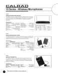
Two-console 8 port PS/2 KVM Switch:
Two-console 16 port PS/2 KVM Switch:
1
Chapter 1: Introduction
Features
• 8/16 port Two-Console PS/2 KVM switch is standard 1U 19” rack mount size design.
• Support one local console and one CAT5 remote console up to 500 feet away from KVM
switch.
• Support Microsoft® Intellimouse®, Microsoft® Intellimouse® Explorer, Logitech Net Mouse or the
other fully compatible MS mice.
• Support DOS, Win3.X, Win95/98/98SE/2000/ME/XP, WinNT, Netware, Unix, Linux.
• Support iMAC, Power MAC and Sun Microsystems with USB port (USB-PS/2 adapter
required).
• Hot Plug - Add computers or Remove Connected computers for Maintenance without
Powering off the KVM switch or computers.
• Very High Video Quality - Up To 1920X1440, Bandwidth: 200MHz.
• No Software Required - easy computer selection via On Screen Display Menu, Push Buttons,
and Hot Keys.
• Support eight-character password protection and computer server name searching.
• Auto-Scan Mode for monitoring computers with flexible Scan time from 5~99 seconds.
• Keyboard status restored when switching computers.
• LED Display for easy status monitoring.
• Buzzer sound for switching port confirmation.
• One extra daisy chain port built-in without using existing computer ports.
• Auto-detect of daisy chain bank - No manual DIP switch setting needed.
Package contents
Model No.: Two-console 8 port PS/2 KVM Switch
8 port PS/2 KVM Switch with CAT5 remote console port
1 pc.
CAT 5 Remote Console Receiver
1 pc.
Power Adapter DC9V, 500mA (for KVM Switch)
1 pc.
Power Adapter DC9V, 500mA (for CAT5 Remote Console Receiver)
Rack Mount Kit
1 pc.
1 SET
User’s manual
1 pc.
Model No.: Two-console 16 port PS/2 KVM Switch
16 port PS/2 KVM Switch with CAT5 remote console port
1 pc.
CAT 5 Remote Console Receiver
1 pc.
Power Adapter DC9V, 500mA (for KVM Switch)
1 pc.
Power Adapter DC9V, 500mA (for CAT5 Remote Console Receiver)
Rack Mount Kit
1 pc.
1 SET
User’s manual
1 pc.
2
Chapter 1: Introduction
Technical Specifications
Model No.
Two-console 8 port
PS/2 KVM Switch
Two-console 16 port
PS/2 KVM Switch
Computer Port
9 (8 local and 1 remote)
17 (16 local and 1 remote)
Console Port
2 (1 local and 1 remote)
2 (1 local and 1 remote)
Computer Port Connector
(All Female Types)
VGA HDDB 15pin (shared with PS/2 keyboard and Mouse)
Console Port Connector
Local Console:
PS/2 Keyboard (Mini Din 6 pin)
PS/2 Mouse (Mini Din 6 pin)
VGA HDDB 15pin
Remote Console: RJ-45 4P8C
(All Female Types)
Daisy Chain Port Connector
(All Female Type)
PS/2 Keyboard (Mini Din 6 pin)
PS/2 Mouse (Mini Din 6 pin)
VGA HDDB 15pin
Computer selection
On Screen Display Menu, Hot Key, Push Button
Computer Port LED
16
Bank 7 segment LED
1
32
On Screen Display Control
Yes
Scan Intervals
5~99 Sec.
Keyboard Emulation
PS/2
Mouse Emulation
PS/2
VGA Resolution
1920X1440
Bandwidth
200MHz
Daisy Chain MAX Level
8 levels
MAX Computer Connection
120+1 (120 local and 1 remote) 128+1 (128 local and 1 remote)
Housing (KVM Switch)
Metal
KVM Switch Power Adapter
DC 9V, 500mA
Cat5 Remote Console
Receiver Power Adapter
DC 9V, 500mA
Operation Temperature
0 to 50°C (32 to 122°F)
Storage Temperature
-20 to 60°C (-4 to 140°F)
Humidity
0 to 95%, Non-Condensing
Size
19” Rack Mount / 1RU
19” Rack Mount / 1RU
Weight (g) (KVM Switch)
2010 (4.43 pounds)
2220 (4.89 pounds)
Weight (g) (CAT5 Receiver)
120 (0.26 pounds)
120 (0.26 pounds)
Dimension (cm) (KVM Switch)
41 x 16.4 x 4.5 (16.14 x 6.46 x 1.77 in.)
41 x 16.4 x 4.5 (16.14 x 6.46 x 1.77 in.)
Dimension (cm) (CAT5 Receiver) 11.15 x 7.5 x 3.95 (4.39 x 2.95 x 1.56 in.) 11.15 x 7.5 x 3.95 (4.39 x 2.95 x 1.56 in.)
3
Chapter 1: Introduction
System Requirements
Model No.
Two-console 8 port PS/2 KVM Switch
Local Console side
One VGA Monitor
One PS/2 Keyboard
One PS/2 Mouse
One DC9V 500mA power adapter
One CAT5 cable
One KVM CAT5 receiver
One DC9V 500mA power adapter
One VGA Monitor
One PS/2 Keyboard
One PS/2 Mouse
One 3 to 3 KVM cable (KCB-3036F or KCB-3031)
1 to 3 Hi Density KVM cable (KCB-1236F or KCB-1231)
(HDDB 15 pin male to one HDDB 15 pin video and Mini Din 6 pin
keyboard and mouse connectors)
Note: One per computer, max. 8 per switch
Remote Console side
Computer side
Model No.
Two-Console 16 port PS/2 KVM Switch
Console side
One VGA Monitor
One PS/2 Keyboard
One PS/2 Mouse
One DC9V 500mA power adapter
One CAT5 cable
One KVM CAT5 receiver
One DC9V 500mA power adapter
One VGA Monitor
One PS/2 Keyboard
One PS/2 Mouse
One 3 to 3 KVM cable (KCB-3036F or KCB-3031)
1 to 3 Hi Density KVM cable (KCB-1236F or KCB-1231)
(HDDB 15 pin male to one HDDB 15 pin video and Mini Din 6 pin
keyboard and mouse connectors)
Note: One per computer, max. 16 per switch
Remote Console side
Computer side
4
Chapter 1: Introduction
Cable Diagrams
Computer Port Special Cable:
1 to 3 Hi Density KVM cable (KCB-1236F or KCB-1231) HDDB 15 pin male to one HDDB 15
pin video and Mini Din 6 pin keyboard and mouse connectors
AT to PS/2 keyboard adapter: (Optional)
Din 5 pin Male to Mini Din 6 pin Female
Daisy Chain Cable:
PS/2 Cable:
Din 5 pin Male to Mini Din 6 pin Female
VGA Cable:
HDDB15 pin Male to Male
CAT5/5E/6 Straight Through UTP/STP Cable:
4P8C
5
Chapter 2: Hardware Installation
Before installation, please make sure all the peripherals and computers have been turned off.
The installation below is based on 8 port-Rack Mount KVM Switch. Please follow the same
installation procedure for the 16 port Rack Mount KVM Switch.
Step 1
Find a convenient place to put your KVM Switch. Its 19” rack mount form factor makes it ideal to
be mounted on a 19” rack. When mounting to a rack, attach the included brackets to the sides
of the KVM Switch. Take note of the length of your cables so that your computers, KVM Switch,
keyboard, mouse and monitor are distanced properly.
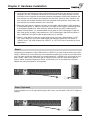
Step 2 (Local Console)
Connect the monitor to the KVM Switch. Connect the attached cable, or the one included with
your monitor, to the HDDB-15 female port on the back of the KVM unit marked with the monitor
symbol at the CONSOLE connector.
6
Chapter 2: Hardware Installation
Step 3
Connect the keyboard to the KVM Switch. If you have an AT type keyboard, you will need an AT
to PS/2 adapter.
Step 4
Connect the mouse to the KVM Switch.
Step 4-1 (Remote Console)
Extending your computer console up to 500 feet away:
(1)
Make sure the CAT5 cable used is a straight through type. (see page 5)
(2)
Plug one end of the CAT5 cable into the RJ-45 connector of the PS/2 KVM switch and the
other end into KVM CAT5 receiver RJ-45 port.
(3)
Connect remote keyboard, mouse and monitor with PS/2-EXTENDER-RECEIVER “KB“,
“MS“ and “Monitor” interface.
(4)
Connect CAT5 receiver computer port with computer console port by using 3 to 3 KVM
cable.
7
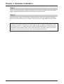
Chapter 2: Hardware Installation
NOTE:
1. Local console and Remote console of KVM Switch will have the same priority to control
computer, just like a computer connected to two consoles. The remote console can control both the local computer and remote computer connected to KVM switch; however, the
local console can only control the computers on local side. There will be a conflict, if the
local console and remote console access the computer simultaneously. Please don’t use
local console and remote console at the same time.
2. When the video signal is foggy or un-clear on the screen, please check if VGA connector
is connected properly, or the VGA resolution is too high for the length of cable being used.
If the problem happened at VGA resolution, please shorten the CAT5 cable length or
reduce VGA resolution. It is recommended to use “optimal CAT5 cable length” to get the
best video quality and don’t add unnecessary CAT5 cable length. High VGA resolution is
up to 1280X1024 and CAT5 cable length could be up to 500 feet.
3. There is a Dip Switch on the rear of the KVM switch. The factory default value is “OFF/
OFF” state. When you use CAT5 cable length over 300 feet, please set DIP Switch to
“ON/ON” state. The other settings like “ON/OFF” or “OFF/ON” state is reserved for future
applications.
Step 5
Computer port connectors of the KVM switch are HDDB-15 pin type. Plug the end of the cable
which is HDDB-15 pin male connector to the selected computer port on the rear of KVM switch
unit. The other end of the cable which has three connectors: a HDDB-15 pin male type for computers video, a Mini Din 6 pin female type for keyboard and a Mini Din 6 pin female type for
mouse, will be attached to keyboard, mouse and monitor ports of the respective computer.
Repeat the same procedure for all computers.
Step 6 (Optional)
If your computer has an AT type keyboard port (Din 5 pin), you will need a PS/2 to AT keyboard
adapter.
8
Chapter 2: Hardware Installation
Step 7
Check all of the connections carefully. The keyboard and mouse connectors are color coded to
help in connecting the keyboard and mouse cables to the correct ports.
Step 8
Attach the power supply to the KVM unit and plug the other end into an electrical receptacle.
Now you will see the LED for Port 1 light up, and you will hear a beep. Switch on your monitor.
NOTE:
Though the computers connected to KVM Switch are able to support enough power to the
stand alone switch, it is suggested that the power adapter be plugged in. The KVM Switch
will need a power adapter to daisy chain more banks and if you forget to plug in the power
adapter on the status of daisy chain, it may cause unexpected operation.
9
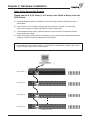
Chapter 2: Hardware Installation
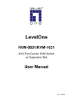
Daisy Chain Connection Diagram
Please use the 3 ft (91.44cm), 3 to 3 daisy chain Cable to daisy chain the
KVM Switch.
A. Connect Keyboard, Mouse and Monitor to the console port (white color block) of bank 1
KVM switch.
B.
Use one end of 3 to 3 Cable to connect the daisy chain port of bank 1 and the other
end to the console port (white color block) of bank 2 KVM switch.
C. Please repeat item B to daisy chain more bank as you want. But, the maximum level of
daisy chain bank is eight.
D.
While chaining the slave bank up to six banks, you may need a VGA extender between the
fifth bank and the sixth bank to enhance the VGA signal.
NOTE:
If you would like to daisy chain 8 port, or 16 port PS/2 or KVM Switch together, the master
bank must be 16 port PS/2 or KVM Switch
Master (Bank 1)
Slave (Bank 2)
Slave (Bank 3)
Slave (Bank 8)
Maximum 8 Levels
10
Chapter 3: Console Operation
Password Protection
There is an administration password for locking the console display and switching between managed computers. This password can be set by using the OSD. The password supports up to 8
digits, and only accepts “ A~Z ” , “ 0~9 ” . The default password is “ 00000000 ” . For security
reasons, please change the default password the first time you configure the KVM switch. It is
strongly recommend to write down the new password. If the password is forgotten, you will need
to contact the vendor to erase the password that had been set.
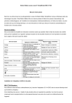
Selecting Computer Using Push Button
Current Active Bank Display
Bank Select
Port Status
Port Select
Reset Button:
Press Port Select and Bank Select of bank 1 (master) simultaneously to reset KVM switch. This
reset action will not only return KVM switch back to initial state but it will also re-check any slave
banks which are connected to the master KVM switch.
If you add a new KVM SWITCH as a slave bank, please use reset button of master KVM switch
to assign a new ID to the slave. You can view the new slave bank by using the OSD menu after
the reset.
Example:
To access a computer attached to Port 3 of the first Bank. First, you can push Bank Select once,
and the Bank No will display current Active (1) Bank. Then you can push Port Select three times
and the Port No will display Port Status (3) Port.
Keyboard Hot Key Commands:
You can also conveniently command KVM switch to switch ports simple via key sequences.
To send commands to KVM switch, the “SCROLL LOCK” key must be pressed twice within
2 seconds. You will hear a beep for confirmation and then the keyboard is in hot key mode.
If you have not pressed any key in hot key mode within 2 seconds (It means there is no
keystroke after “Scroll Lock” “Scroll Lock” key ), the keyboard will be back to Operation
System control state.
11
Chapter 3: Console Operation
Selecting Computer Using Hot Key
You can conveniently command your KVM SWITCH by keyboard hot key entry. To send commands to the KVM SWITCH, the “SCROLL LOCK” key must be pressed twice within 2 seconds,
then you will hear a confirmation beep that the keyboard is in hot key mode. If you have not
pressed any additional key in hot key mode within 2 seconds, the keyboard will return back to
the normal Operation System control state.
Below are the hot key commands list:
This Combination
Does This
Scroll Lock
Scroll Lock
=
Previous Channel
Scroll Lock
Scroll Lock
=
Next Channel
(Note: You could also press “up arrow key”
or “down arrow key” to speed up selection
of the destination port)
Scroll Lock
Scroll Lock
Page Up
=
Previous Bank
Scroll Lock
Scroll Lock
Page Down
=
Next Bank
Scroll Lock
Scroll Lock
Bank No +
Port No
=
Computer Selection
Scroll Lock
Scroll Lock
B
=
Beeper
(Note: The default Beeper function is ON)
Scroll Lock
Scroll Lock
S
=
Scroll Lock
Scroll Lock
R
=
Scroll Lock
Scroll Lock
F
=
Search the same computer name
(Note: Search computer name starts from
1st computer port)
Scroll Lock
Scroll Lock
Space bar
=
On Screen Display Menu
Auto Scan
OSD default value
(Note: 1. Rom re-flash command takes
2~3 minutes. 2.Not including password)
NOTE:
1. If you enable the scan mode command, the KVM switch will issue one Beep for confirmation each time one of the KVM ports hop to the next KVM port.
2. To get out of Auto Scan Mode, press any key or Space bar.
3. If you are trying to access a single digit port no. precede the port no. with a zero (0).
Example: To access bank 3 and port 2, press “SCROLL LOCK” twice followed by the
“302” value.
12
Chapter 3: Console Operation
Selecting Computer through Hot Key - Example
Example:
A.
To access a computer attached to Port 2 of Bank 3. You can press through hot key as below:
Scroll lock + Scroll lock + 3 + 0 + 2
B.
To access a computer attached to next Bank, You can press through hot key as below:
Scroll lock + Scroll lock + Page Down
NOTE:
Use numeric keys on the keyboard to select Bank no. and Port no. Numeric keys on the keypad are not available as a hot key command.
13
Chapter 3: Console Operation
Hot Plug Function
KVM switch supports “ Hot Plug ” function. When mouse/keyboard connection has been
changed from one port to the other, it is not necessary to reboot the managed computer for the
change to take effect.
NOTE:
Some O.S. (Operation Systems) like SCO Unix are unable to support “ Hot Plug ” function. If
you apply “Hot Plug” to this kind of O.S., it will cause unpredictable behavior or shut down
the computer. Before using “ Hot Plug ” , please make sure your O.S. and mouse software
driver supports the “Hot Plug” function.
14
Chapter 3: Console Operation
OSD OPERATION Details
When you access the OSD menu by using the hot keys, you will see the following window pop
up on your monitor.
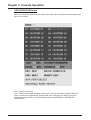
The 1st line bar is Bank No.
The 2nd block is your KVM’s computer system name list. You will find the system number list
from 01 to 08. You can define your system name with a maximum of 8 levels. The factory
default of the 8 port KVM (or 16 for KVM-16H) switch is “SYSTEM 01”, “SYSTEM 02”,…,
“SYSTEM 08”.
15
Chapter 3: Console Operation
OSD OPERATION Details
Sun symbol “
The sun symbol “
status.
” indicates a powered on status for the KVM port.
” beside the computer system name shows that computer is at powered on
Use up arrow key “
” or down arrow key “
” to select KVM port.
Use up arrow key “ ” or down arrow key “ ” to select port for destination computer system
name. After selecting the KVM port you want, press the ENTER Key to immediately switch to
that KVM port.
Use “PgUp” or “PgDn” key for selecting previous or next Bank No.
Use “PgUp“ key or “PgDn” key for selecting previous or next Bank No. (or KVM unit No.)
Press “Insert” key for editing computer name.
Press “INS” key for editing computer system name. When editing is finished, press the “Enter”
key to save the information.
Press “Tab” key to select Bank, OSD, Scan…etc.
Use “Tab” key to select items like Bank, OSD, SCAN, CHANGE PASSWORD, CONSOLE
ON/OFF, etc…
16
Chapter 3: Console Operation
OSD OPERATION Details continued
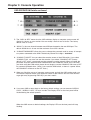
1. The “OSD: 10 SEC” means that the OSD windows display or computer system name will
display for 10 sec. on your monitor. You can modify it from 05 sec to 99 sec. The factory
default value is 10 sec.
2. “SCAN ” is the scan interval between one KVM port hopped to the next KVM port. The
default SCAN time is 10 sec and the maximum scan time is 99 sec.
3. “CHANGE PASSWORD” allows the user to change the password used to access all computer systems connected to the KVM. The default password is 8 digits “ 00000000”.
4. “CONSOLE ON/OFF“ lets you select the console access of the KVM switch. If you select
“CONSOLE ON“, any user can use the console. If you select “CONSOLE OFF“(factory
default is OFF state), a password must be entered to use the console. When you enter the
password and pass the KVM switch authentication, the CONSOLE will be set to ON. After
you finish using the KVM switch, please do not forget to set the CONSOLE ON state to OFF
for password authentication. ( Note: If you reset the KVM switch, or there is a power failure,
the CONSOLE will be set at the OFF state. )
5. When you finish the set-up of computer system name and exit the OSD setting mode, you
will find the computer name at the upper-left corner of the monitor. You can clear the message right away by pressing ESC key if you don’t need it.
6. If you want OSD to return back to the factory default settings, you can execute “SCROLL
LOCK”, “SCROLL LOCK”, “R” keys in order. The Display LEDs on the front panel will be
flashed during the refresh process.
When the OSD returns to default settings, the Display LEDs on the front panel will stop
flashing.
17
Chapter 4: Troubleshooting
1.
Make sure that all cables are well connected. Label all of cables with the number for each computer
respectively to avoid confusion.
2.
To avoid ghosting and degradation, the recommended VGA cable distance is 5 meters (16.4 feet)
maximum. Normally, the cable length is based on driver capacity of your VGA card. If you need a
longer VGA cable, please use a VGA extender to accomplish your application.
3.
The recommended PS/2 cable distance is 5 meters (16.4 feet) maximum. Normally, the cable length
is based on driver capacity of your motherboard PS/2 port. If you need longer PS/2 cable, please
use PS/2 extender to accomplish your applications.
4.
Don’t press any keys on the keyboard while the selected computer is booting up. Otherwise, it might
cause the keyboard error or keyboard is not detected at computer side.
5.
The computer boot up is fine, but keyboard doesn’t work
• Make sure the keyboard works when it is directly plugged into the computer.
• Try a different keyboard, but use only 101, 102 or 104-key keyboard.
6.
The Mouse is not detected during computer boot up.
• Make sure the mouse works when directly plugged into the computer.
• Make sure the mouse is a true PS/2 mouse. A combo mouse will work just as long as it is set for
PS/2 mode with the correct adapter. Try a different mouse.
• Avoiding moving the mouse or pressing the mouse buttons when switching ports.
• Avoiding switching ports during shutting down the computer process.
• When you switch one computer port to another, please set the scan time for 5 sec at least.
Normally, it takes one or tow seconds for the VGA monitor to change from one resolution mode
to another. So, the scan time is not recommended to be less than 5 seconds.
7.
The power switch is off, but the switch still works fine or power adapter is unplugged from the
switch, but the switch still works fine. KVM Switch unit draws the power source from power adapter
and all computer’s PS/2 port. Some computer’s PS/2 port can support enough power for the switch,
but some computer’s PS/2 port ( like laptop, notebook computer…etc.) is unable to supply enough
power for the switch. In order to make sure the system can work steadily, please do not set power
switch as off state or remove the power adapter from the switch. Although the computers connected
to KVM Switch unit are able to support enough power to the stand alone switch, KVM Switch unit
still needs a power adapter for daisy chain more banks.
8.
If you forget the “ password ” you typed, please contact your supplier.
9.
CAT5 Console Receiver power LED is not ON, to make sure power adapter is connected to KVM
CAT5 receiver.
10. No video signal is displayed on the remote monitor.
a. It might happen because VGA cables & connecter and CAT5 cable & connector is loosed or
disconnected or VGA cable was not attached to computer during boot up process.
b. Or power adapter is not connected to receiver.
11. When video signal is foggy or un-clear on the screen, please check if VGA connector is connected
properly, or if the VGA resolution is too high for the length of cable being used. If the problem happened at VGA resolution, please shorten the CAT5 cable length or reduce VGA resolution. It is highly recommended to use optimal CAT5 cable length to get the best video quality and avoid adding
unnecessary CAT5 cable length. VGA resolution is up to 1280X1024 and CAT5 cable length could
be up to 500 feet approximately.
18
Certifications
FCC
This equipment has been tested and found to comply with Part 15 of the FCC Rules. Operation
is subject to the following two conditions:
(1) This device may not cause harmful interference
(2) This device must accept any interference received. Including interference that may cause
undesired operation.
CE – Certificate
This equipment is in compliance with the requirements of the following regulations:
EN 55 022: CLASS B
19
© 2005 freedom9 Inc.