1
®
2620A/2625A
Hydra Series II Data Acquisition Unit
Hydra Series II Data Logger
Users Manual
PN 686675
November 1997
© 1997 Fluke Corporation, All rights reserved. Printed in U.S.A.
All product names are trademarks of their respective companies.
LIMITED WARRANTY & LIMITATION OF LIABILITY
Each Fluke product is warranted to be free from defects in material and workmanship under
normal use and service. The warranty period is one year and begins on the date of shipment.
Parts, product repairs and services are warranted for 90 days. This warranty extends only to the
original buyer or end-user customer of a Fluke authorized reseller, and does not apply to fuses,
disposable batteries or to any product which, in Fluke’s opinion, has been misused, altered,
neglected or damaged by accident or abnormal conditions of operation or handling. Fluke
warrants that software will operate substantially in accordance with its functional specifications for
90 days and that it has been properly recorded on non-defective media. Fluke does not warrant
that software will be error free or operate without interruption.
Fluke authorized resellers shall extend this warranty on new and unused products to end-user
customers only but have no authority to extend a greater or different warranty on behalf of Fluke.
Warranty support is available if product is purchased through a Fluke authorized sales outlet or
Buyer has paid the applicable international price. Fluke reserves the right to invoice Buyer for
importation costs of repair/replacement parts when product purchased in one country is submitted
for repair in another country.
Fluke’s warranty obligation is limited, at Fluke’s option, to refund of the purchase price, free of
charge repair, or replacement of a defective product which is returned to a Fluke authorized
service center within the warranty period.
To obtain warranty service, contact your nearest Fluke authorized service center or send the
product, with a description of the difficulty, postage and insurance prepaid (FOB Destination), to
the nearest Fluke authorized service center. Fluke assumes no risk for damage in transit.
Following warranty repair, the product will be returned to Buyer, transportation prepaid (FOB
Destination). If Fluke determines that the failure was caused by misuse, alteration, accident or
abnormal condition of operation or handling, Fluke will provide an estimate of repair costs and
obtain authorization before commencing the work. Following repair, the product will be returned to
the Buyer transportation prepaid and the Buyer will be billed for the repair and return
transportation charges (FOB Shipping Point).
THIS WARRANTY IS BUYER’S SOLE AND EXCLUSIVE REMEDY AND IS IN LIEU OF ALL
OTHER WARRANTIES, EXPRESS OR IMPLIED, INCLUDING BUT NOT LIMITED TO ANY
IMPLIED WARRANTY OF MERCHANTABILITY OR FITNESS FOR A PARTICULAR PURPOSE.
FLUKE SHALL NOT BE LIABLE FOR ANY SPECIAL, INDIRECT, INCIDENTAL OR
CONSEQUENTIAL DAMAGES OR LOSSES, INCLUDING LOSS OF DATA, WHETHER
ARISING FROM BREACH OF WARRANTY OR BASED ON CONTRACT, TORT, RELIANCE OR
ANY OTHER THEORY.
Since some countries or states do not allow limitation of the term of an implied warranty, or
exclusion or limitation of incidental or consequential damages, the limitations and exclusions of
this warranty may not apply to every buyer. If any provision of this Warranty is held invalid or
unenforceable by a court of competent jurisdiction, such holding will not affect the validity or
enforceability of any other provision.
Fluke Corporation
P.O. Box 9090
Everett, WA 98206-9090
U.S.A.
5/94
Fluke Europe B.V.
P.O. Box 1186
5602 BD Eindhoven
The Netherlands
Table of Contents
Chapter
1
Title
Introduction........................................................................................ 1-1
The Hydra Series II Data Acquisition Unit .......................................................
The Hydra Series II Data Logger ......................................................................
Options and Accessories ...................................................................................
Applications Software...................................................................................
IEEE-488 Interface Assembly.......................................................................
Connector Set (2620A-100) ..........................................................................
Accessories....................................................................................................
Where to go From Here.....................................................................................
2
Page
1-3
1-3
1-3
1-3
1-3
1-3
1-5
1-5
Overview............................................................................................. 2-1
Introduction .......................................................................................................
Setting Up the Instrument..................................................................................
Unpacking and Inspecting the Instrument.....................................................
Adjusting the Handle ....................................................................................
Line Power ....................................................................................................
Front/Rear Panel Features.............................................................................
Input Channels ..............................................................................................
Operating Modes ...............................................................................................
Turning the Instrument On ................................................................................
Front Panel Display ...........................................................................................
Reading the Display ..........................................................................................
Left Display...................................................................................................
Right Display ................................................................................................
Specific Annunciators ...................................................................................
Front Panel Buttons ...........................................................................................
Selecting a Channel.......................................................................................
Using the Buttons..........................................................................................
Setting up a Channel..........................................................................................
Setting Alarm Limits and Mx+B Scaling Values..............................................
Alarm Limits .................................................................................................
Mx+B Scaling ...............................................................................................
Setting the Scan Interval....................................................................................
Using the Monitor Function ..............................................................................
i
2-3
2-3
2-3
2-3
2-4
2-4
2-9
2-9
2-9
2-10
2-10
2-10
2-10
2-10
2-11
2-11
2-11
2-12
2-14
2-14
2-15
2-15
2-16
2620A/2625A
Users Manual
Using the Scan Function....................................................................................
Reviewing Channel Data...................................................................................
Viewing the Totalizer Count .............................................................................
Using External DC Power .................................................................................
Using the Rack Mount Kit.................................................................................
3
Operating the Instrument from the Front Panel............................... 3-1
Introduction .......................................................................................................
Operating Modes ...............................................................................................
Other Displayed Data ........................................................................................
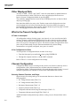
What is the Present Configuration?...................................................................
If Power is Interrupted ..................................................................................
If the Configuration is Reset .........................................................................
Channel Configuration ......................................................................................
Selecting Channel, Function, and Range ......................................................
Setting Alarms...............................................................................................
Alarm Limits.............................................................................................
Alarm Indications .....................................................................................
Resetting Alarm Conditions .....................................................................
Using the Digital I/O Lines ...........................................................................
Mx+B Scaling ...............................................................................................
Instrument Configuration ..................................................................................
Entering and Changing Numeric Values.......................................................
Selecting Scan Interval..................................................................................
Selecting the Measurement Rate...................................................................
Triggering......................................................................................................
External Triggering .......................................................................................
Changing the Temperature Unit....................................................................
Setting Date and Time of Day.......................................................................
Measurement Connections ................................................................................
DC Volts, AC Volts, Frequency, and Thermocouples..................................
Resistance and RTD......................................................................................
Totalizing...........................................................................................................
General ..........................................................................................................
Connections...................................................................................................
Review Array.....................................................................................................
List Button Functions ........................................................................................
Autoprint ...........................................................................................................
Memory Storage ................................................................................................
Front Panel Lock out Conditions.......................................................................
Front Panel Review Only Function...............................................................
Front Panel Monitor Only Function..............................................................
Computer Interface-Initiated Lockouts .........................................................
REM Annunciator .............................................................................................
Calibration .........................................................................................................
4
2-16
2-16
2-17
2-17
2-18
3-3
3-3
3-4
3-4
3-4
3-4
3-4
3-4
3-9
3-9
3-10
3-11
3-11
3-12
3-14
3-14
3-15
3-15
3-16
3-16
3-16
3-17
3-17
3-18
3-20
3-22
3-22
3-22
3-22
3-23
3-25
3-25
3-26
3-26
3-26
3-27
3-27
3-27
Using the Computer Interface ........................................................... 4-1
Introduction .......................................................................................................
Front Panel and Computer Interface Operations...........................................
Types of Computer Interface ........................................................................
Using the RS-232 Computer Interface ..............................................................
Setting Communication Parameters (RS-232) ..............................................
Autoprint and Memory Storage (RS-232).....................................................
ii
4-3
4-3
4-3
4-3
4-4
4-5
Contents (continued)
Autoprint: Computer Interface Control ....................................................
Autoprint: Output Format .........................................................................
Memory Storage: Computer Interface Control.........................................
Memory Retrieval .....................................................................................
Memory Full Operation ............................................................................
Clearing Memory......................................................................................
Cabling the Instrument to a Host or Printer (RS-232) ..................................
Installation Test.............................................................................................
RS-232 Information.......................................................................................
Character Echoing ....................................................................................
Character Deletion....................................................................................
Device Clear Using Ctrl C........................................................................
RS-232 Prompts ........................................................................................
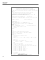
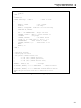
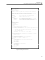
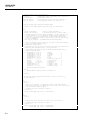
Sample Program Using the RS-232 Computer Interface ..............................
Using the IEEE-488 Interface............................................................................
IEEE-488 Operating Limitations ..................................................................
Installing the IEEE-488 Interface..................................................................
Enabling the IEEE-488 Interface ..................................................................
Installation Test.............................................................................................
General Information (RS-232 and IEEE-488)...................................................
How the Instrument Processes Input.............................................................
Input Strings..............................................................................................
Input Terminators .....................................................................................
Typical Input Strings ................................................................................
Sending Numeric Values to the Instrument (RS-232 and IEEE-488) ......
Sending Input Strings to the Instrument ...................................................
How the Instrument Processes Output ..........................................................
Service Requests (IEEE-488 only) and Status Registers ..............................
Event Status and Event Status Enable Registers ......................................
Status Byte Register..................................................................................
Reading the Status Byte Register .............................................................
Service Request Enable Register ..............................................................
Instrument Event Register ........................................................................
Computer Interface Command Set ....................................................................
5
4-5
4-5
4-6
4-6
4-7
4-7
4-7
4-8
4-8
4-8
4-8
4-8
4-9
4-9
4-9
4-9
4-9
4-12
4-13
4-13
4-13
4-14
4-14
4-14
4-16
4-16
4-16
4-17
4-19
4-19
4-20
4-21
4-21
4-22
Additional Considerations ................................................................ 5-1
Introduction .......................................................................................................
Measurement Rate.............................................................................................
Advanced Trigger Mechanisms.........................................................................
Front Panel Trigger Control..........................................................................
Computer Interface Trigger Control .............................................................
Both External and Monitor Alarms Disabled (Type 0) ................................
External Trigger Enabled (Type 1) ...............................................................
Monitor Alarm Enabled (Type 2) .................................................................
Thermal Voltages ..............................................................................................
When Measuring Resistance or Temperature (RTD)........................................
True RMS Measurements..................................................................................
Effects of Internal Noise in AC Measurements ............................................
Waveform Comparison (True RMS vs Average Responding) .....................
Making Mixed Measurements...........................................................................
Using Shielded Wiring ......................................................................................
General Rule .................................................................................................
Alternate Suggestions ...................................................................................
Non-Isolated Sensor Configuration ..........................................................
iii
5-3
5-3
5-3
5-3
5-3
5-4
5-4
5-6
5-6
5-6
5-8
5-8
5-8
5-9
5-11
5-11
5-11
5-11
2620A/2625A
Users Manual
Isolated and Shielded Sensor Configuration ............................................ 5-11
In More Detail ............................................................................................... 5-12
6
Maintenance ....................................................................................... 6-1
Introduction .......................................................................................................
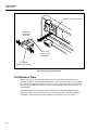
Cleaning.............................................................................................................
Line Fuse ...........................................................................................................
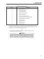
Self-Test Diagnostics and Error Codes .............................................................
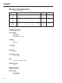
Performance Tests .............................................................................................
Accuracy Verification Test ...........................................................................
Channel Integrity Test...................................................................................
Thermocouple Measurement Range Accuracy Test .....................................
4-Terminal Resistance Test...........................................................................
Thermocouple Temperature Accuracy Test..................................................
Open Thermocouple Response Test .............................................................
RTD Temperature Accuracy Test .................................................................
RTD Temperature Accuracy Test (Using Decade Resistance Source) ....
RTD Temperature Accuracy Test (Using DIN/IEC 751) .........................
Digital Input/Output Verification Tests ........................................................
Digital Output Test ...................................................................................
Digital Input Test......................................................................................
Totalizer Test............................................................................................
Totalizer Sensitivity Test..........................................................................
Dedicated Alarm Output Test .......................................................................
External Trigger Input Test...........................................................................
Calibration .........................................................................................................
Variations in the Display...................................................................................
Service ...............................................................................................................
6-3
6-3
6-3
6-3
6-4
6-7
6-7
6-9
6-10
6-11
6-13
6-14
6-14
6-15
6-15
6-16
6-16
6-17
6-18
6-19
6-21
6-21
6-22
6-22
Appendices
A
B
C
D
E
F
Specifications..............................................................................................
ASCII & IEEE-488 Bus Codes ...................................................................
IEEE-488.2 Devise Documentation Requirements.....................................
Making Mixed Measurements ....................................................................
Binary Upload of Logged Data (LOG_BIN?) (2625A only)......................
RS-232 Cabling...........................................................................................
Index
iv
A-1
B-1
C-1
D-1
E-1
F-1
List of Tables
Table
1-1.
1-2.
2-1.
2-2.
2-3.
3-1.
3-2.
3-3.
3-4.
3-5.
3-6.
3-7.
3-8.
3-9.
3-10.
3-11.
3-12.
3-13.
3-14.
3-15.
3-16.
3-17.
3-18.
3-19.
4-1.
4-2.
4-3.
4-4.
4-5.
4-6.
4-7.
4-8.
5-1.
6-1.
6-2.
Title
Hydra Features.......................................................................................................
Accessories ............................................................................................................
Display Annunciators ............................................................................................
Front Panel Pushbuttons ........................................................................................
Review Array.........................................................................................................
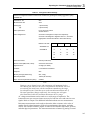
Configuration Reset Settings .................................................................................
DC Voltage, AC Voltage .......................................................................................
Resistance ..............................................................................................................
Frequency...............................................................................................................
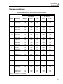
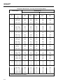
Thermocouple Temperature...................................................................................
RTD Temperature..................................................................................................
Alarm Selection .....................................................................................................
Initial Alarm Assignments, Digital I/O Lines 4 Through 7 ...................................
Mx+B Selection .....................................................................................................
Scan Interval ..........................................................................................................
Measurement Rate Selection .................................................................................
Trigger Type Selection ..........................................................................................
Date/Time Selection ..............................................................................................
Thermocouple Ranges ...........................................................................................
Review Array.........................................................................................................
List Button Operation ............................................................................................
Autoprint/Memory Storage Selection....................................................................
Clearing Memory Storage......................................................................................
REM Annunciation................................................................................................
RS-232 Setup .........................................................................................................
IEEE-488.1 Capabilities ........................................................................................
IEEE-488 Setup .....................................................................................................
Status Byte Register...............................................................................................
Event Status Register .............................................................................................
Instrument Event Register (IER) ...........................................................................
Command and Query Summary.............................................................................
Command and Query Reference............................................................................
Ohms Test Voltage ................................................................................................
Power-Up Error Codes...........................................................................................
Recommended Test Equipment .............................................................................
v
Page
1-4
1-5
2-7
2-11
2-17
3-5
3-6
3-7
3-7
3-8
3-9
3-10
3-12
3-14
3-15
3-16
3-16
3-17
3-20
3-23
3-24
3-26
3-26
3-27
4-4
4-12
4-12
4-19
4-20
4-22
4-23
4-26
5-8
6-5
6-6
2620A/2625A
Users Manual
6-3.
6-4.
6-5.
6-6.
6-7.
E-1.
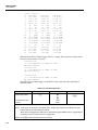
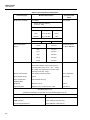
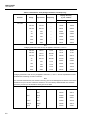
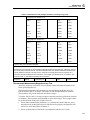
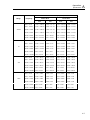
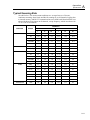
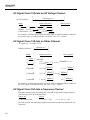
Performance Tests (Voltage, Resistance, and Frequency) .................................... 6-8
Performance Tests for Thermocouple Temperature Function (IPTS-68/ITS-90) . 6-13
Performance Tests for RTD Temperature Function (Resistance) (DIN/IEC 751
Amendment 1) (IPTS-68) ...................................................................................... 6-14
Performance Tests for RTD Temperature Function (DIN/IEC 751 Amendment 1)
(IPTS-68) ............................................................................................................... 6-15
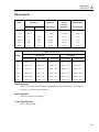
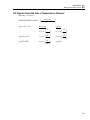
Digital Input Values............................................................................................... 6-17
Floating Point Format ............................................................................................ E-4
vi
List of Figures
Figure
2-1.
2-2.
2-3.
2-4.
2-5.
2-6.
3-1.
3-2.
3-3.
3-4.
4-1.
4-2.
4-3.
4-4.
5-1.
5-2.
5-3.
6-1.
6-2.
6-3.
6-4.
6-5.
E-1.
E-2.
E-3.
F-1.
F-2.
F-3.
F-4.
F-5.
F-6.
Title
Adjusting Handle ...................................................................................................
Front Panel.............................................................................................................
Left Display ...........................................................................................................
Right Display .........................................................................................................
Annunciators..........................................................................................................
Rear View ..............................................................................................................
Configuration Mode...............................................................................................
Input Module Connections ....................................................................................
2-Terminal and 4-Terminal Connections...............................................................
Totalizing Connection ...........................................................................................
Data/Stop Bits........................................................................................................
Sample Program.....................................................................................................
Typical Input Strings .............................................................................................
Overview of Status Data Registers ........................................................................
External Trigger Timing ........................................................................................
2T and 4T-Connections .........................................................................................
Comparison of Common Waveforms ....................................................................
Replacing the Line Fuse ........................................................................................
4-Terminal Connections to 5700A ........................................................................
4-Terminal Connections to Decade Resistance Box .............................................
Dedicated Alarms Output Test ..............................................................................
External Trigger Test.............................................................................................
ASCII String Decoding..........................................................................................
Floating Point Conversion .....................................................................................
Example .................................................................................................................
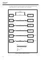
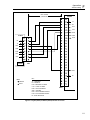
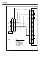
Summary of RS-232 Connections .........................................................................
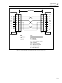
Hydra (DB-9) to PC (DB-9) RS-232 Connection (Generic) .................................
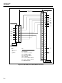
Hydra (DB-9) to PC (DB-25) RS-232 Connection................................................
Hydra (DB-9) to Modem (DB-25) RS-232 Connection ........................................
Hydra (DB-9) to Printer (DB-25) RS-232 Connection..........................................
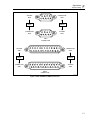
RS-232 DB9 and DB-25 Connectors.....................................................................
vii
Page
2-3
2-5
2-6
2-6
2-6
2-8
3-3
3-19
3-21
3-22
4-4
4-10
4-15
4-18
5-5
5-7
5-10
6-4
6-12
6-13
6-20
6-21
E-2
E-5
E-6
F-3
F-4
F-5
F-6
F-7
F-8
Caution
THIS IS AN IEC SAFETY CLASS 1 PRODUCT. BEFORE USING, THE GROUND WIRE IN THE
LINE CORD OR THE REAR PANEL BINDING POST MUST BE CONNECTED FOR SAFETY.
Interference Information
This equipment generates and uses radio frequency energy and if not installed and used in strict
accordance with the manufacturer’s instructions, may cause interference to radio and television
reception. It has been type tested and found to comply with the limits for a Class B computing
device in accordance with the specifications of Part 15 of FCC Rules, which are designed to
provide reasonable protection against such interference in a residential installation.
Operation is subject to the following two conditions:
•
This device may not cause harmful interference.
•
This device must accept any interference received, including interference that may cause
undesired operation.
There is no guarantee that interference will not occur in a particular installation. If this equipment
does cause interference to radio or television reception, which can be determined by turning the
equipment off and on, the user is encouraged to try to correct the interference by one of more of
the following measures:
•
Reorient the receiving antenna
•
Relocate the equipment with respect to the receiver
•
Move the equipment away from the receiver
•
Plug the equipment into a different outlet so that the computer and receiver are on different
branch circuits
If necessary, the user should consult the dealer or an experienced radio/television technician for
additional suggestions. The user may find the following booklet prepared by the Federal
Communications Commission helpful: How to Identify and Resolve Radio-TV Interference
Problems. This booklet is available from the U.S. Government Printing Office, Washington, D.C.
20402. Stock No. 004-000-00345-4.
Declaration of the Manufacturer or Importer
We hereby certify that the Fluke Model 2620A Data Acquisition Unit and 2625A Data Logger are in
compliance with BMPT Vfg 243/1991 and is RFI suppressed. The normal operation of some
equipment (e.g. signal generators) may be subject to specific restrictions. Please observe the
notices in the users manual. The marketing and sales of the equipment was reported to the
Central Office for Telecommunication Permits (BZT). The right to retest this equipment to verify
compliance with the regulation was given to the BZT.
Bescheinigung des Herstellers/Importeurs
Hiermit wird bescheinigt, daβ Fluke Model 2620A Data Acquisition Unit and 2625A Data Logger in
Übereinstimung mit den Bestimmungen der BMPT-AmtsblVfg 243/1991 funk-entstört ist. Der
vorschriftsmäßige Betrieb mancher Geräte (z.B. Meßsender) kann allerdings gewissen
Einschränkungen unterliegen. Beachten Sie deshalb die Hinweise in der Bedienungsanleitung.
Dem Bundesamt für Zulassungen in der Telekcommunikation wurde das Inverkehrbringen dieses
Gerätes angezeigt und die Berechtigung zur Überprüfung der Seire auf Einhaltung der
Bestimmungen eingeräumt.
Fluke Corporation
viii
Safety Terms in this Manual
This instrument has been designed and tested in accordance with IEC publication 1010,
Safety Requirements for Electrical Measuring, control and Laboratory Equipment. This
Users Manual contains information, warnings, and cautions that must be followed to
ensure safe operation and to maintain the instrument in a safe condition. Use of this
equipment in a manner not specified herein may impair the protection provided by the
equipment.
The meter is designed for IEC 664, Installation Category II use. It is not designed for use
in circuits rated over 4800VA.
Warning statements identify conditions or practices that could result in personal injury
or loss of life.
Caution statements identify conditions or practices that could result in damage to
equipment.
Symbols Marked on Equipment
Danger - High voltage.
Ground (earth) terminal.
Protective ground (earth) terminal. Must be connected to safety earth
ground when the power cord is not used. See Chapter 2.
Attention - refer to the manual. This symbol indicates that information
about usage of a feature is contained in the manual. This symbol appears
in the following two places on the instrument rear panel:
1. Ground Binding Post (left of line power connector). Refer to "Using
External DC Power" in Chapter 2.
2. Alarm Outputs/Digital I/O Connectors. Refer to Appendix A,
Specifications.
Warning
To avoid electric shock:
•
When the input module is installed, consider all channels
with connections as accessible terminals that may be
hazardous live.
•
Disconnect the input module before touching or changing
external wiring.
•
Remove inputs from live voltages before opening the input
module.
ix
2620A/2625A
Users Manual
AC Power Source
The instrument is intended to operate from an ac power source that will not apply more
than 264V ac rms between the supply conductors or between either supply conductor and
ground. A protective ground connection by way of the grounding conductor in the power
cord is required for safe operation.
DC Power Source
The instrument may also be operated from a 9 to 16V dc power source when either the
rear panel ground binding post or the power cord grounding conductor is properly
connected.
Use the Proper Fuse
To avoid fire hazard, use only a fuse identical in type, voltage rating, and current rating
as specified on the rear panel fuse rating label.
Grounding the Instrument
The instrument utilizes controlled overvoltage techniques that require the instrument to
be grounded whenever normal mode or common mode ac voltages or transient voltages
may occur. The enclosure must be grounded through the grounding conductor of the
power cord, or if operated on battery with the power cord unplugged, through the rear
panel ground binding post.
Use the Proper Power Cord
Use only the power cord and connector appropriate for the voltage and plug
configuration in your country.
Use only a power cord that is in good condition.
Refer cord and connector changes to qualified service personnel.
Do Not Operate in Explosive Atmospheres
To avoid explosion, do not operate the instrument in an atmosphere of explosive gas.
Do Not Remove Cover
To avoid personal injury or death, do not remove the instrument cover. Do not operate
the instrument without the cover properly installed. Normal calibration is accomplished
with the cover closed, and there are no user-serviceable parts inside the instrument, so
there is no need for the operator to ever remove the cover. Access procedures and the
warnings for such procedures are contained in the Service Manual. Service procedures
are for qualified service personnel only.
Do Not Attempt to Operate if Protection may be Impaired
If the instrument appears damaged or operates abnormally, protection may be impaired.
Do not attempt to operate it. When in doubt, have the instrument serviced.
x
Getting Started
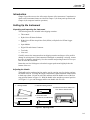
Introduction
This section will have you operating Hydra in a matter of minutes. All basic operating
information is covered in this short Getting Started guide. Subsequent chapters of the
manual cover the instrument in more detail.
Note
This manual contains information and warnings that must be followed to
ensure safe operation and retain the instrument in safe condition.
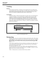
The Basics
Hydra has 21 input channels: channel 0 is on the front panel, and channels 1 through 20
are on the rear input module.
There are two ways Hydra takes measurements (these can be used separately or
together):
•
A Scan function, which measures all channels at a specified scan interval.
•
A Monitor function, which repeatedly measures any one channel.
The instrument has three different modes of operation:
•
Active Mode - when the Scan and/or Monitor functions are on.
•
Configuration Mode - when any of the setup parameters are being changed.
•
Inactive mode - when the instrument is powered up, and sitting idle (i.e., not in
Active Mode or Configuration Mode).
Turning On the Instrument
Press R ON. The entire display lights up as the instrument steps through a series of
self tests. (Refer to Chapter 6 if any error messages are displayed during this self-test
sequence.) When the self-tests are finished, the instrument resumes whatever mode it
was in the last time power went off.
Normally it will go to Inactive Mode, and sit idle with a channel number on the righthand display. You can change the displayed channel with G and D. Other annunciators
are lit dimly to provide a summary description of the selected channel’s setup.
The initial setup for all channels should be "off": as you scroll through the channels with
G or D, the "OFF" annunciator should be on dimly. If any of the channels are set up
otherwise, or if the instrument immediately starts taking measurements after the self-test
sequence, then it still contains the previous user’s setup. You can quickly get the
instrument back to the initial setup by performing a "Configuration Reset".
To perform a Configuration Reset, press R OFF. Then hold C in, while pressing
R ON; keep C pressed until the self-test sequence is finished and the instrument
beeps one time.
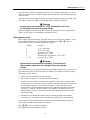
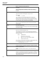
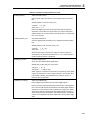
Setting Up a Channel
1. Press G, D to select a channel to modify. For this example, start with channel 0.
2. Press F to access the function setup menu.
The "SET" and "FUNC" annunciators come on, and the instrument goes into
Configuration Mode. The present function for this channel is also highlighted (for
xi
2620A/2625A
Users Manual
this example, "OFF" is lit if you’re working with channel 0, and have already
performed the Configuration Reset).
3. Press G, D to cycle through the choices for measurement function. For now, select
"V AC", to set up the channel for AC voltage measurements.
4. Press E to confirm your choice. The instrument then offers a choice of
measurement ranges for this function, starting with "Auto" for autoranging.
5. Press G, D to cycle through the choices for range. Select the 300v range. (300v is
available only on channels 0, 1 and 11.)
6. Press E to confirm your choice.
This completes setting up channel 0 to measure AC voltage. The instrument returns to
Inactive Mode, and the new setup for channel 0 is shown dimly on the display.
The sequence for setting up a channel to measure DC Voltage, Frequency or Resistance
is very similar:
1. Press G, D to select a channel to set up.
2. Press F to access the function setup menu.
3. Press G, D to cycle through the choices for measurement function, then press
E.
4. Press G, D to cycle through the choices for range, then press E. This
completes the setup for the channel and the instrument returns to Inactive Mode.
When you set up a channel to measure resistance, the instrument also lets you choose 2Terminal or 4-Terminal measurements ("2T" or "4T") before returning to Inactive Mode.
Note that 4-Terminal measurements are supported only on channels 1 - 10.
The sequence for setting up a channel to measure temperature is similar:
1. Press G, D to select a channel to set up.
2. Press F to access the function setup menu.
3. Press G, D to select "°C" from the list of measurement functions, then press E.
(Chapter 3 of the manual explains how to change temperature measurement units.)
4. The instrument then offers a choice of 9 different thermocouple types, as well as
"Pt" for platinum RTD’s.
Press G, D to select a thermocouple type, then press E. This completes the setup
for the channel and the instrument returns to Inactive Mode.
When setting up a channel to measure RTD’s, the instrument also prompts for 2Terminal vs 4-Terminal measurements, and then allows you to specify a value for R0.
(Note that Channel 0 cannot be set up to measure thermocouples or 4-Terminal RTD’s.)
Subsequent sections of the manual explain how to set up alarm values and Mx+B linear
scaling for each channel.
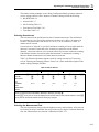
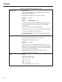
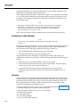
Selecting the Scan Data Destination
The 2620A will always send the scan data to the RS-232 printer port, following each
scan. The 2625A can be configured to send the scan data to the RS-232 printer port, or to
the internal Memory Storage, or to both simultaneously. Begin this procedure by
selecting MODE (shift print). Select the scan data destination (“dESt” in the right
display) as “Print” (left display) to send the data to the RS-232 port, as “StoreE” to send
the data to Memory Storage, or as “both” for simultaneous storage and printing. Then
xii
Getting Started (continued)
select the mode (“Mode” in right display) from “All” to output all scan data, “ALAr” to
output only alarm data, or “trAnS” to output data scanned only when the Hydra goes into
or out of alarm.
Once the destination and mode have been set, enable Memory Storage by pressing: print.
The “PRN” annunciator lights to indicate that Memory Storage is enabled.
Warning
No data will be saved unless the “PRN” annunciator is lit on the
on the Hydra from panel florescent display.
Memory contents can be sent to the RS-232 port for listing directly to a printer (refer to
Table 3-16 in Chapter 3) or through the computer interface.
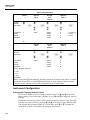
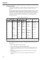
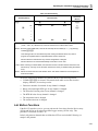
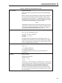
Taking Measurements
Before taking any measurements, you might want to set up a few more channels... set up
three additional channels, as described below. (Remember, use G or D when in
inactive Mode to select a channel, and then press F.)
Channel
Function
0
1
2
3
4
5 .. 20
V AC, 300V range
V DC, 30V range
(leave set up as "OFF")
Resistance, 3 mΩ range
Thermocouple Temperature ("°C" or "°F")
(leave set up as "OFF")
Warning
Inputs may be connected to live voltages. To avoid electric
shock remove inputs from live voltages before opening this
module.
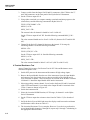
You need to connect wires to these channels before taking measurements. Insert a pair of
test leads into the jacks on the front panel for channel 0. For channels on the rear Input
Module, proceed as follows:
1. Remove the input module from the rear panel.
2. Loosen the two large screws on top and open the module.
3. Connect wires to the pairs of terminals for channels 1 and 3. We’ve enclosed some
thermocouple wire for you to connect to channel 4; the thermocouple’s red lead must
be connected to the "low" input terminal, labeled "L". (Note that the enclosed
thermocouple is for demonstration purposes only. Measurements taken with it may
be off by 1 - 2 degrees.) Refer to Table 3-14 in Chapter 3 to identify the type of
thermocouple by positive lead color. This table also shows the appropriate usable
temperature range.
4. Thread the wires through the strain-relief pins and out the back of the module.
5. Close the cover, secure the screws, and insert the module back in the instrument.
The instrument is now ready to take measurements. Start with the Monitor function,
which takes repeated measurements on a channel.
Press G, D to select a channel to Monitor.
Press M to activate the monitor function.
xiii
2620A/2625A
Users Manual
Note
You cannot activate the Monitor function if the selected channel is set up
as OFF; the instrument gives a long beep and ignores your request.
The "MON" annunciator comes on, and the instrument starts taking measurements on the
selected channel. If you haven’t connected the input leads to a signal, the instrument
simply displays a nominal noise reading; on channels set up to measure resistance, "OL"
is displayed for overload. (The instrument also displays "OL", or "otc" for open
thermocouple, when attempting to measure temperatures on channels to which no sensor
has been connected.)
Press G, D to scroll through other channels and take additional measurements. Note
that the instrument automatically skips over channels that are not set up (i.e., those
channels still set to "OFF").
Press M to deactivate the Monitor function when you’re through. ( M toggles the
Monitor function on and off.)
Next, press Q to activate the Scan function. The "Scan" annunciator comes on, and the
instrument begins taking measurements on all the channels you’ve set up.
When the scan completes, the instrument normally then counts down the time interval
remaining until the next scan is due. (the countdown appears on the right display.)
However, if you performed a Configuration Reset, then the scan interval has been set
back to 0:00:00. Under this condition, the instrument performs continuous scanning.
Subsequent sections of the manual explain how to change the scan interval.
Even with the scan function on, you can still use the Monitor function to watch a
channel:
Press M to activate the Monitor function.
Press G, D to change the monitor channel, as desired. (The instrument continues to
take scan measurements in the background.)
Press M to deactivate the Monitor function when you are through.
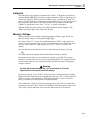
Similarly, press Q to deactivate the Scan function when you are through.
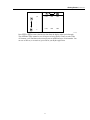
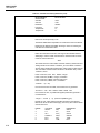
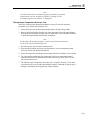
Viewing Minimum, Maximum, and Last Data Values
While taking scan measurements, the instrument also collects Minimum, Maximum and
Last values for each channel. These values are stored in the "Review Array." You can
examine the data in the Review array when the instrument is in Active Mode or Inactive
Mode. If you are in Active Mode, (i.e. the Scan and/or Monitor functions are on), the
instrument will continue to take measurements in the background while you examine the
Review data.
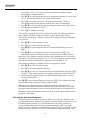
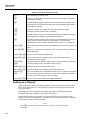
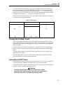
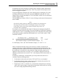
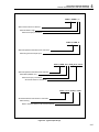
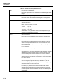
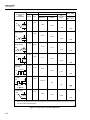
Press N to call up the Review array onto the display.
Use the four arrow buttons to examine different entries in the Review array. The arrow
buttons move around in the Review array, as illustrated below.
xiv
Getting Started (continued)
20
.
.
.
.
.
.
.
0
LAST
MIN
MAX
LAST
MIN
MAX
oo24f.eps
Press N or C to remove the Review data from the display when you’re through.
The remainder of this manual covers all aspects of using Hydra. Glance over the Table
of Contents; you’ll find that each section presents an additional layer of information. You
can use as little as (or as much as) you need for your Hydra application.
xv
2620A/2625A
Users Manual
xvi
Chapter 1
Introduction
Title
The Hydra Series II Data Acquisition Unit .......................................................
The Hydra Series II Data Logger ......................................................................
Options and Accessories ...................................................................................
Applications Software .......................................................................................
IEEE-488 Interface Assembly ...........................................................................
Connector Set (2620A-100) ..............................................................................
Accessories........................................................................................................
Where to go From Here.....................................................................................
Page
1-3
1-3
1-3
1-3
1-3
1-3
1-5
1-5
1-1
2620A, 2625A
Users Manual
1-2
Introduction
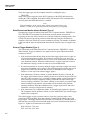
The Hydra Series II Data Acquisition Unit
1
Note
This manual contains information and warnings that must be followed to
ensure safe operation and retain the instrument in safe condition.
The Hydra Series II Data Acquisition Unit
The Hydra Series II Data Acquisition Unit (Model 2620A) is a multi-channel data
acquisition unit able to measure ac and dc voltages, temperature via thermocouples and
RTDs, resistance, and frequency. It features 21 measurement channels, 8 digital
input/output lines, a Totalizer input, and 4 alarm output lines. The Data Acquisition Unit
is easily carried by hand and can be ac or dc powered. The user can choose
communications with a host computer over an RS-232 (standard) or IEEE-488
(2620A/05) computer interface. Refer to Table 1-1 for a list of operating features.
The Hydra Series II Data Logger
The Hydra Series II Data Logger (Model 2625A) combines data logging memory with
the features of the Data Acquisition Unit. The RS-232 computer interface is standard
(IEEE-488 capability is not available.)
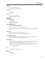
Options and Accessories
Applications Software
The following software packages are available for the instrument:
•
Hydra Starter (included with instrument)
Allows for communication from an IBM-compatible personal computer through the
RS-232 interface, emphasizing transfer of measurement and configuration settings to
and from the instrument.
•
Hydra Logger Package (order separately)
Hydra Logger (model 2635A-901) is a Windows-based package that allows
complete set up and data collection and data conversion from up to 2 Hydra units.
Logger communicates over the RS-232 port on a personal computer and may be used
with telephone modems. Hydra Logger with Trending (model 2635A-902) includes a
comprehensive trending package that simulates a chart recorder. A brochure with
complete details is available.
IEEE-488 Interface Assembly
Model 2620A/05 includes an IEEE-488 Interface. Commands for the IEEE-488 interface
are virtually identical to those used with the RS-232 Interface
If your Hydra Series II Data Acquisition Unit does not have an IEEE-488 Interface, a
field-installable kit (2620A-05K) is available. The Hydra Series II Data Logger cannot
be equipped with an IEEE-488 Interface.
Connector Set (2620A-100)
The 2620A-100 is a complete set of input connectors (one Input Module and two Digital
I/O Connectors). These connectors allow for additional wiring setups so that a single
Hydra Series II Data Acquisition Unit or Data Logger can then be moved among
multiple installations.
1-3
2620A, 2625A
Users Manual
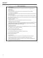
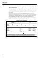
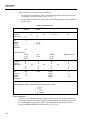
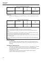
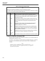
Table 1-1. Hydra Features
•
Channel Scanning
Can be continuous scanning, scanning at an interval time, single scans, or triggered (internal or
external) scans.
•
Channel Monitoring
Make measurements on a single channel and view these measurements on the display.
•
Channel Scanning and Monitoring
View measurements made for the monitor channel while scanning of all active channels continues.
•
Multi-Function Display
Left (numeric) display shows measurement readings; also used when setting numeric parameters.
Right (alphanumeric) display used for numeric entries, channel number selection and display, status
information, and operator prompts.
•
Front-Panel Operation
Almost all operations can be readily controlled with the buttons on the front panel.
•
Measurement Input Function and Range
Volts dc (VDC), volts ac (VAC), frequency (Hz), and resistance (Ω) inputs can be specified in a fixed
measurement range. Autoranging, which allows the instrument to use the measurement range
providing the optimum resolution, can also be selected.
•
Temperature Measurement
Thermocouple types J, K, E, T, N, R, S, and B, and Hoskins Engineering Co. type C are supported.
Also, DIN/IEC 751 Platinum RTDs are supported.
•
Totalize Events on the Totalizing Input
•
Alarm Limits and Digital Output Alarm Indication
•
4-Terminal Resistance Measurements (Channels 1 through 10 only)
•
RS-232 Computer Interface Operation
•
Measurement Rate Selection
•
Nonvolatile Memory
Storage of minimum, maximum, and most recent measurements for all scanned channels.
Storage of Computer Interface setup, channel configurations, and calibration values.
Storage of measurement data: storage for 2047 scans of up to 21 channels, representing up to
42,987 readings (Hydra Data Logger only).
1-4
Introduction
Where to go From Here
1
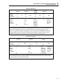
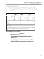
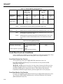
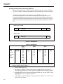
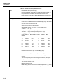
Accessories
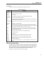
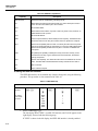
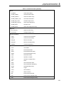
Accessories available for the instrument are described in Table 1-2.
Table 1-2. Accessories
Model
Description
80I-410
80i-1010
Clamp-On DC/AC Current Probes.
80J-10
Current Shunt.
2620A-05K
Field-installable IEEE-488 Option kit (Hydra Data Acquisition Unit only).
2620A-901
Hydra Data Logger Applications Package.
C40
Soft carrying case. Provides padded protection for the instrument. Includes a pocket for
the manual and pouch for the line cord.
M00-200-634
Rackmount Kit. Provides standard 19-inch rack mounting for one instrument (right or left
side).
PM 8922
Switchable x1, x10 passive probe.
RS40
Shielded RS-232 terminal interface cable. Connects the instrument to any terminal or
printer with properly configured DTE connector (DB-25 socket), including an IBM PC(\R),
IBM PC/XT(\R) or IBM PS/2 (models 25, 30, 50, P60, 70, and 80).
RS41
Shielded RS-232 modem cable. Connects the instrument to a modem with properly
configured DB-25 male pin connector. Use an RS40 and an RS41 cable in series to
connect with an IBM PC/AT(\R).
RS42
Serial printer cable. Contact Fluke for list of compatible printers.
TL20
Industrial test lead set.
TL70
Test lead set.
Y8021
Shielded IEEE-488 one-meter cable, with plug and jack at each end.
Y8022
Shielded IEEE-488 two-meter cable, with plug and jack at each end.
Y8023
Shielded IEEE-488 four-meter cable, with plug and jack at each end.
Y9109
Binding post to BNC plug.
Fluke PN
268789
10Ω Precision Resistor, metal film, +/- 1%, 1/8 watt, 100 ppm. For use with 4 - 20 mA
signals.
Where to go From Here
You might want take a minute to familiarize yourself with this manual. Glance through
the table of contents at the front to see the overall layout of the manual and the major
parts of the instrument. If you have questions about specific topics, the Index at the end
of the manual will be useful. Or, just fan through the headers at the top of each page;
each header reveals the chapter number and the chief subject for that page.
The chapters are summarized in the following paragraphs:
1-5
2620A, 2625A
Users Manual
Getting Started
Provides a quick introduction to instrument setup and operation.
Chapter 1 Introduction
Describes standard features, options, and accessories for the Fluke Hydra Series II Data
Acquisition Unit and Hydra Series II Data Logger. Also, this chapter discusses the
organization and intended uses of this manual.
Chapter 2 Overview
Brings the instrument from its shipping container to operating status. This chapter
provides brief descriptions and a quick walk-through of instrument operation. Read this
chapter to gain a feel for instrument use. But please don’t avoid reading Chapter 3 (for
in-depth operation from the front panel) and Chapter 4 (for computer interface
operation); the instrument is far more powerful than suggested in Chapter 2.
Chapter 3 Operating the Instrument from the Front Panel
Describes all capabilities available through front panel control. The features introduced
in Chapter 2 are described more fully, including descriptions for setting up and using
each type of measurement input (dc volts, thermocouple, etc.) and digital input
(Totalizer, etc.) or output (such as alarms). Other features of the Hydra Series II Data
Acquisition Unit and the Hydra Series II Data Logger are also more fully explained.
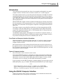
Chapter 4 Using the Computer Interface
Describes connecting the instrument to a terminal or host computer and operating the
instrument over the RS-232 Interface. For the Hydra Series II Data Acquisition Unit
only, use of the optional IEEE-488 Interface is also described here. This chapter is
detailed and requires a good knowledge of instrument operation via the front panel (see
Sections 2 and 3).
Chapter 5 Additional Considerations
Provides detailed operating information not provided elsewhere. This chapter also
describes instrument operation for the advanced user. This chapter is written with the
assumption that you have full knowledge of instrument operation from the front panel
(Chapter 3).
Chapter 6 Maintenance
Provides performance tests (suitable as acceptance testing procedures) and routine
maintenance information. Refer to this chapter for explanation of error codes
encountered during instrument operation. Also, this chapter provides parts ordering
information for such commonly used items as fuses, accessories, and publications.
Refer to the "Hydra Series II Service Manual" (P/N 688868) for complete service, repair,
and parts ordering information.
Appendices
A. Specifications
B. ASCII/IEEE-488 Bus Codes
C. IEEE-488.2 Device Documentation Requirements
D. Making Mixed Measurements Service Centers
E. Binary Upload of Logged Data (LOG_BIN?) (2625A only)
Index
1-6
Chapter 2
Overview
Title
Introduction .......................................................................................................
Setting Up the Instrument..................................................................................
Unpacking and Inspecting the Instrument.....................................................
Adjusting the Handle ....................................................................................
Line Power ....................................................................................................
Front/Rear Panel Features.............................................................................
Input Channels ..............................................................................................
Operating Modes ...............................................................................................
Turning the Instrument On ................................................................................
Front Panel Display ...........................................................................................
Reading the Display ..........................................................................................
Left Display...................................................................................................
Right Display ................................................................................................
Specific Annunciators ...................................................................................
Front Panel Buttons ...........................................................................................
Selecting a Channel.......................................................................................
Using the Buttons..........................................................................................
Setting up a Channel..........................................................................................
Setting Alarm Limits and Mx+B Scaling Values..............................................
Alarm Limits .................................................................................................
Mx+B Scaling ...............................................................................................
Setting the Scan Interval....................................................................................
Using the Monitor Function ..............................................................................
Using the Scan Function....................................................................................
Reviewing Channel Data...................................................................................
Viewing the Totalizer Count .............................................................................
Using External DC Power .................................................................................
Using the Rack Mount Kit.................................................................................
Page
2-3
2-3
2-3
2-3
2-4
2-4
2-9
2-9
2-9
2-10
2-10
2-10
2-10
2-10
2-11
2-11
2-11
2-12
2-14
2-14
2-15
2-15
2-16
2-16
2-16
2-17
2-17
2-18
2-1
2620A, 2625A
Users Manual
2-2
Overview
Introduction
2
Introduction
Chapter 2 provides an overview of the major features of the instrument. Comprehensive
details on all instrument features are found in Chapter 3 (for front panel operation) and
Chapter 4 (for computer interface operation.)
Setting Up the Instrument
Unpacking and Inspecting the Instrument
The following items are included in the shipping container:
•
This manual
•
Hydra Series II Starter Software
•
Hydra Series II Data Acquisition Unit (2620A) or Hydra Series II Data Logger
(2625A)
•
Input Module
•
Digital I/O and Alarms Connector
•
Test leads
•
Line cord
Carefully remove the instrument from its shipping container and inspect it for possible
damage or missing items. If the instrument is damaged or something is missing, contact
the place of purchase immediately. Save the container and packing material in case you
have to return the instrument.
Rotate the rear feet 180 degrees so that their support pads extend slightly below the
bottom of the case.
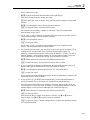
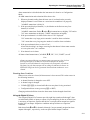
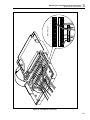
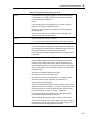
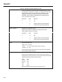
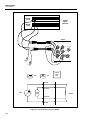
Adjusting the Handle
The handle can be positioned to four angles: one for carrying, two for viewing, and one
for handle removal. To change the angle, simultaneously pull both handle ends outward
to hard stops (about 1/4 inch on each side) and then rotate the handle to one of the four
stop positions shown in Figure 2-1. With the handle in the straight-up removal position
(4 in Figure 2-1), you can disengage and free one handle side at a time.
1. Viewing Position
2. Alternate Viewing Position
Pull One End Out and Towards You.
Then Pull the Other End Out.
3. Carrying Position
4. Removal Position
(to Remove, Pull Ends Out)
COM
VΩ
300V
MAX
oo01f.eps
Figure 2-1. Adjusting Handle
2-3
2620A, 2625A
Users Manual
Line Power
Warning
To avoid shock hazard, connect the instrument power cord to a
power receptacle with earth ground.
Plug the line cord into the connector on the rear of the instrument. The instrument
operates on any line voltage between 90 and 264V ac without adjustment, and at any
frequency between 45 and 440 Hz. However, the instrument is warranted to meet
published specifications only at 50/60 Hz.
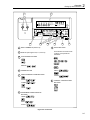
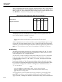
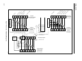
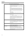
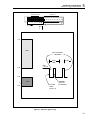
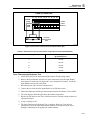
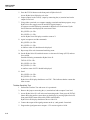
Front/Rear Panel Features
The Front Panel (shown in Figure 2-2) provides a two-terminal input for channel 0, a
multipurpose display, and a set of control buttons. The display includes the following
elements:
•
A major numeric chapter (called the Left Display). See Figure 2-3.
•
An auxiliary alphanumeric chapter (called the Right Display). See Figure 2-4.
•
A set of Display Annunciators. See Figure 2-5 and Table 2-1.
The buttons control all instrument operations: channel configuration, instrument
configuration, measurement functions, and print/communications selections. The buttons
are introduced in this chapter, with a more detailed description following in Chapter 3.
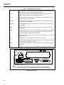
The Rear Panel (shown in Figure 2-6) provides input and output connections: power
input, measurement input, digital input/output, Totalizer input, alarm output, and
computer interface connections. These connections are introduced in this chapter and
explained in greater detail in subsequent chapters of this manual. Inputs and outputs are
described with their related functions (Measuring DC Voltage, Totalizing, etc.) in
Chapter 3. RS-232 and IEEE-488 Computer Interface connections are detailed in
Chapter 4.
2-4
Overview
Setting Up the Instrument
1
2
MAX
MIN
REVIEW
LAST
REM SCAN
AUTO MON
VΩ
COM
2
FUNC
300V
MAX
SET FUNC
Mx+B ALARM
°C °F RO
mV AC DC
x1Mk Ω Hz
ALRM
RATE
Mx+B
CANCL
ENTER
F
LIMIT HI OFF PRN CH
1 2 LO CAL EXT TR
INTVL
PRINT
REVIEW
CLOCK
MODE
CLEAR
SHIFT
LIST
TOTAL
LOCAL
COMM
ZERO
CAL
ENABLE
SCAN
SINGLE
MON
TRIGS
POWER
8
7
1
INPUT TERMINALS (Channel 0)
2
DISPLAY (See Figures 2-3, 2-4, and 2-5)
3
ACTIVE MODE BUTTONS
5
6
7
4
OTHER BUTTONS
These buttons are used to both
configure and operate the
instrument:
,
SINGLE (
POWER BUTTON
5
PRINT/COMMUNICATIONS BUTTONS
6
,
,
)
4
MODE (
)
COMM (
)
LOCAL (
3
8
ZERO (
)
CLEAR (
)
CHANNEL CONFIGURATION
BUTTONS
)
INSTRUMENT CONFIGURATION
BUTTONS
TRIGS (
RATE (
CLOCK (
)
)
)
oo02f.eps
Figure 2-2. Front Panel
2-5
2620A, 2625A
Users Manual
REVIEW
LAST
MAX
MIN
REM SCAN
AUTO MON
SET FUNC
Mx+B ALARM
°C °F RO
mV AC DC
x1Mk Ω Hz
F
LIMIT HI OFF PRN CH
1 2 LO CAL EXT TR
oo03f.eps
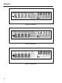
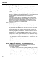
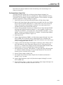
Figure 2-3. Left Display
REVIEW
LAST
MAX
MIN
REM SCAN
AUTO MON
SET FUNC
Mx+B ALARM
°C °F RO
mV AC DC
x1Mk Ω Hz
F
LIMIT HI OFF PRN CH
1 2 LO CAL EXT TR
oo04f.eps
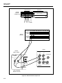
Figure 2-4. Right Display
REVIEW
LAST
MAX
MIN
REM SCAN
AUTO MON
SET FUNC
Mx+B ALARM
°C °F RO
mV AC DC
x1Mk Ω Hz
F
LIMIT HI OFF PRN CH
1 2 LO CAL EXT TR
oo05f.eps
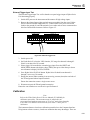
Figure 2-5. Annunciators
2-6
Overview
Setting Up the Instrument
2
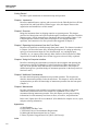
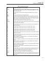
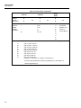
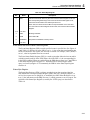
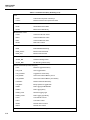
Table 2-1. Display Annunciators
MON
Indicates that the Monitor function is enabled.
SCAN
Indicates that the Scan function is enabled. Scanning can be enabled as a single
scan (SINGLE K Q), with a scan interval, with an alarm-triggered scan, or as an
externally triggered scan.
CH
Indicates that the channel number is displayed immediately above, in the right
display.
SET
Lit when the instrument is in Configuration Mode.
Mx+B
Lit while Mx+B scaling is being defined and when a measurement on the display
has been scaled with an M value other than 1 and/or a B value other than 0. Also
dimly lit when in the Inactive Mode to indicate that an M value other than 1 and/or a
B value other than 0 has been defined for this channel.
FUNC
Lit when a measurement function is being defined for this channel.
ALARM
Lit when alarm values are being defined for this channel or when an alarm limit has
been exceeded while measuring.
V
Indicates that the measurement function is volts for this channel (used with the AC
or DC annunciator).
DC
Indicates that the measurement function is dc voltage for this channel.
AC
Indicates that the measurement function is ac voltage for this channel.
Ω
Indicates that the measurement function is resistance for this channel.
Hz
Indicates that the measurement function is frequency for this channel.
°C
Indicates that the measurement function is temperature for this channel and that the
degree unit is Celsius.
°F
Indicates that the measurement function is temperature for this channel and that the
degree unit is Fahrenheit.
m
(milli) a multiplier for the displayed value, e.g., mV for millivolts. Also used when
defining alarm and Mx+B values.
x1
(times 1) a multiplier for the displayed value. Used when defining alarm and Mx+B
values.
k
(kilo) a multiplier for the displayed value, e.g., kHz for kilohertz. Also used when
defining alarm and Mx+B values.
M
(mega) a multiplier for the displayed value, e.g., MΩ for megohms. Also used when
defining alarm and Mx+B values.
R0
Lit when the ice point resistance is being defined for RTD measurements on the
displayed channel.
OFF
Indicates there is no measurement function defined for the displayed channel; OFF
channels are skipped over when scanning. OFF is also used when defining an
alarm value to indicate that the alarm limit is to be ignored.
AUTO
Indicates that autoranging is enabled for the displayed channel.
LIMIT
Used with the S and T annunciators when you are setting an alarm limit value. Also
lit when displaying a measurement value (LAST, Monitor) which has exceeded an
alarm limit.
2-7
2620A, 2625A
Users Manual
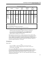
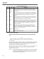
Table 2-1. Display Annunciators (cont)
"1"
Lit when alarm limit 1 is being defined. Also lit when displaying a measurement
value (LAST, Monitor) which has exceeded alarm limit 1.
"2"
Lit when alarm limit 2 is being defined. Also lit when displaying a measurement
value (LAST, Monitor) which has exceeded alarm limit 2.
HI, LO
Identifies alarm limit sensing (high or low) during channel configuration. At other
times, identifies an alarm condition.
REVIEW
Indicates that review data is being displayed (used in conjunction with the MIN,
MAX, and LAST annunciators).
MIN, MAX
Indicates that the displayed value is the minimum (maximum) value measured on
this channel.
LAST
Indicates that the displayed value is the most recent scan measurement taken on
this channel.
PRN
Indicates that the autoprint function is enabled (to send readings to a printer) or the
memory storage function is on (to store readings in internal memory.) Internal
memory is available with Hydra Data Logger only.
F
Bright when memory storage is full, dim when memory storage is nearly full. Hydra
Data Logger only.
EXT
Indicates that external triggering (on the rear panel) is enabled.
TR
Indicates that internal triggering (from the monitor alarm) is enabled. Also used with
EXT when external triggering is enabled.
REM
Indicates that the instrument is under the remote control of one of the computer
interfaces.
CAL
Indicates that the instrument’s internal calibration constants have been corrupted.
CAUTION
FOR FIRE PROTECTION REPLACE WITH T 1/8A 250V (SLOW) FUSE
MODEL: 2620
2625
90-264V
50/60 Hz
15VA
ALARM OUTPUTS
DIGITAL I/O
+ –– 00 11 22 33 TR
+
TR
9-16 V
DC PWR
IEC 664 INSTALLATIONCATEGORY II
RS-232C
IEEE STD-488 PORT
0 1 2 3 4 5 6 7 Σ
+30V
!
MEETS 0871 B
COMPLIES FCC-15B
GND TX
DTR RX
SH1, AH1, T5, L4, SR1, RL1, DC1, DT1, PP0, C0, E1
EXTERNAL BATTERY
WARNING: If voltages greater than 30V are to be measured, a safety ground must be attached
to the rear panel ground connector when the instrument is operated from battery power.
oo06f.eps
Figure 2-6. Rear View
2-8
Overview
Operating Modes
2
Input Channels
The instrument provides one input (channel 0) on the front panel and 20 inputs (channels
1 .. 20) through a connector on the rear panel. Channels 0, 1, and 11 can measure a
maximum of 300V; all other channels can measure a maximum of 150V.
Caution
The maximum input that can be applied between any terminal
of channels 2..10 and 12..20 is 150V dc or ac rms. The
maximum input that can be applied between any terminal of
channels 0, 1, and 11 and ground is 300V dc or ac rms. The
maximum common mode input that can be applied is 300V dc
or ac rms.
Operating Modes
The instrument provides three modes of operation:
•
Active Mode
The instrument is in Active Mode whenever the Monitor and/or Scan functions are
enabled. Scans are activated by the interval timer, an external trigger, an alarm
trigger, or a single scan (SINGLE K Q) command. When in Active Mode, the
MON and/or SCAN annunciators are lighted.
•
Configuration Mode
The instrument is in Configuration Mode whenever settings (channel function, alarm
values, Mx+B scaling values, scan interval, trigger type, etc.) are being examined or
changed. When in the Configuration Mode, the SET annunciator is on, along with
other annunciators indicating the parameter(s) being set.
•
Inactive Mode
The instrument is in Inactive Mode when no measurement functions are enabled and
no instrument settings are being examined or changed. This is a quiescent state; only
summary channel information is displayed.
Turning the Instrument On
Turn the instrument on by pressing POWER on the lower right of the front panel.
Initially, the entire display lights while the instrument conducts several internal self tests.
Note
You can familiarize yourself with the instrument by holding the display
fully lit. Press and hold K, then press R ON and wait a moment for
the instrument to beep. Then release K. The entire display will now stay
on until you press any button; the power-up sequence then resumes.
A deviation in mainframe software Version 5.5 will not allow the display to
remain ON. Versions 5.4 and below will allow the display to remain ON.
Any error conditions are momentarily displayed during this test sequence. Even in the
presence of an error, the instrument still attempts to complete the self-test sequence and
begin normal operation. However, if you encounter an error, note the number and refer
to Self Test Diagnostics and Error Codes in Chapter 6 for additional information.
Once the self tests are completed, the instrument enters Inactive or Active Mode,
depending on the following circumstances:
2-9
2620A, 2625A
Users Manual
•
Active Mode if this mode was in effect prior to the cycling of power. Scanning,
monitoring, or combined scanning/monitoring is resumed.
•
Inactive Mode if the instrument was in Inactive Mode or Configuration Mode prior
to cycling of power.
When in Inactive Mode, the instrument shows configuration information for the
displayed channel. The channel number appears in the right display, and other
annunciators are dimly lit to show the present setup for this channel. For example, if the
channel is set up to measure ke, the "k" and "e" annunciators are dimly lit.
Alternatively, if this channel has not been set up to measure anything, the "OFF"
annunciator is lit dimly.
You can change the channel by pressing G or D.
Front Panel Display
Full descriptions of the display annunciators are presented in Table 2-1.
Reading the Display
The instrument display uses both alphanumeric characters and fixed annunciators. When
in Configuration Mode, these features are used to provide user prompting. In Inactive
Mode, they provide status information. In Active Mode, they provide both status
information and measurement data.
Information is presented on the display during both front panel control and computer
interface control. If the instrument is being controlled through a computer interface, the
display shows the results of computer-interface initiated actions (even if the front panel
controls have been disabled.)
The remainder of Chapter 2 (as well as Chapter 3) relates to front panel control of the
instrument. Refer to Chapter 4 for additional information about computer interface
operation.
Left Display
The left display has five large numeric characters to show measurement results, "otc"
when an open thermocouple is detected, or "OL" when a measurement is over range.
During Configuration Mode, the left display is also used to display the numeric values
and instrument parameters being chosen.
Right Display
The right display has five small alphanumeric characters to show the channel number,
display prompting information during setups, or to count down the scan interval.
Specific Annunciators
The rest of the display is devoted to specific annunciators, combinations of which are
used to describe the operating mode, the type of measurement being displayed, or the
type of setup information to be entered. These annunciators are described in Table 2-1
and shown in Figure 2-5.
2-10
Overview
Front Panel Buttons
2
Front Panel Buttons
Go ahead and press any front panel button. The instrument always provides an audible
response to each button press. Valid entries yield a short beep; incorrect entries yield a
longer beep. Don’t worry if you press an inappropriate button and get a long beep; you
can’t damage the instrument. It will discard the button entry and wait for another entry.
Selecting a Channel
The channel number appears in the right display. Press G or D to select a channel. You
can change the channel when in Inactive Mode, when looking at data in the Review
array, or when the Monitor function is on.
Using the Buttons
Table 2-2 presents a summary of the control buttons.
Special button sequences cause a total instrument Configuration Reset or change the
temperature units between °C and °F.
•
Holding D down while turning the power on causes the instrument to perform a
Configuration Reset. Hold the button down until the instrument beeps, indicating
that the action has been taken. All channels will be reset OFF. All alarm and scaling
values will be reset. Scanning and monitoring will be turned off.
•
Holding B down while cycling POWER ON toggles the degree unit used with
temperature measurements (°C or °F). Again, the instrument will beep and display
°C or °F when this action is complete.
Table 2-2. Front Panel Pushbuttons
F
Calls up the menu to set the function for the channel.
A
Calls up the menu to set alarm limits S and T for the channel.
B
Calls up the menu to set scaling on the channel.
GDJH
Used to change the channel number and to step through choices in any of the
setup menus. These arrow buttons have an automatic repeat action when held
down for more than 1 second.
G generates a service request when the instrument is under remote control without
local lockout (REMS).
E
Used to accept a selection just made in any setup menu.
D
Used to exit setup menu and return to Inactive Mode, without saving settings you’ve
selected thus far. Exceptions exist under the following two conditions:
•
If you cancel out of the alarm menu part way through defining alarm limit T, any
just-made entries for alarm limit S will still take effect.
•
If you cancel out of the Mx+B menu partway through defining the B value, any
just-made changes to the M value will still take effect.
This button also provides a handy way to remove the Totalizer value or Review
data from the display.
Q
Turns the Scan function on or off.
Q triggers a single scan when the instrument is under remote control without
lockout (REMS).
2-11
2620A, 2625A
Users Manual
Table 2-2. Front Panel Pushbuttons (cont)
M
Turns the Monitor function on or off.
I
Allows you to change the scan interval. Scanning becomes continuous when the
interval is set to 0:00:00.
U
Enables/disables logging measurements to the printer (Autoprint - RS-232 only) or
to internal data memory (Memory Storage). Only the Hydra Data Logger provides
internal Memory Storage.
N
Calls up the Review array of MIN, MAX and LAST values to the display.
O
Calls up the present Totalizer count to the display.
L
(RS-232 only) Prints out the Last values of the Review array (2620A and 2625A) or
Data Logger memory (2625A only) via the RS-232 interface.
K
Accesses secondary functions under various keys, as described below. When this
button is pressed, "SHIFt" appears on the right display, but automatically
disappears if you have not made a selection within 5 seconds or if you press D.
(K)
When under remote control without lockout (REMS), this returns control to the front
panel.
(K J)
Allows you to change the scanning speed: "Slo" for highest accuracy, or "FASt" for
highest throughput.
LOCAL
RATE
(K I) Allows you to set the internal day/date clock.
CLOCK
(K U)
MODE
Allows you to select the conditions for which scan measurements will be
automatically printed or logged.
CLEAR
(K
COMM
(K L) Allows you to set up a computer interface port.
N)
ZERO
(K O) While the Totalizer count is displayed, resets the Totalizer to 0.
SINGLE
Q)
TRIGS
This button sequence clears the entire contents of the Review array. Review data
must be presently shown on the display to clear the array.
(K
(K M)
Forces an immediate scan of all defined channels. If a scan is presently in progress,
this new request is ignored. Once begun, the full scan is completed. Configuration
changes are not allowed while a scan is in progress.
Allows you to set up the auxiliary scan trigger mechanisms.
Setting up a Channel
Channel set ups are made in Configuration Mode, which must be entered from Inactive
Mode. If the instrument is in Active Mode, turn the Scan and/or Monitor function off
before proceeding.
Follow the steps below to change the channel setup. More detailed instructions for
setting all instrument parameters are provided in Chapter 3.
During the following steps, note that some items on the display are brightly lit, and
others are dimly lit. The bright item is intended to focus your attention on the choice the
instrument is offering you at that moment.
Note
Press D to exit the channel setup menu at any time, leaving the old setup
unchanged.
2-12
Overview
Setting up a Channel
2
1. Select a channel to set up:
G D Look for the desired channel number in the right display.
2. Press the following buttons to change the setup:
F SET and FUNC come on bright, along with the present setting for measurement
function.
G D Cycle through the choices for measurement function.
E Accept your choice of measurement function.
For resistance measurements, continue on with steps 3 and 4. For temperature
measurements, skip to step 5.
3. For dc volts, ac volts, resistance, or frequency, the instrument now provides a choice
of measurement ranges. Press the buttons as follows:
G D Cycle through the choices.
E Accept your choice.
For dc volts, ac volts, or frequency, the configuration is now complete for this
channel. The instrument returns to Inactive Mode.
4. For resistance measurements, one more step is required to specify 2-terminal (2T) or
4-terminal (4T) measurements. Since 4-terminal measurements require two
channels, 4-terminal measurements can be set up on channels 1-10 only. For each 4terminal channel, a corresponding channel (11-20) ten numbers higher is reserved
for the additional two connections required. Press the buttons as follows:
G D Choose between two terminals (2T) and four terminals (4T).
E Accept your choice. The instrument returns to Inactive Mode.
5. If you’ve specified temperature measurements, the instrument provides a choice of
thermocouple types or Platinum RTD. Press the buttons as follows:
G D Cycle through the thermocouple choices. "Pt" is the RTD choice.
E Accept your choice.
If you selected one of the thermocouple types, channel configuration is complete; the
instrument returns to Inactive Mode.
6. If you selected "Pt" (for RTD-based measurements), use the following buttons to
specify 2-terminal (2T) or 4-terminal (4T) measurements and the R0 value.
Since 4T measurements require two channels, 4-terminal measurements can be set
up on channels 1-10 only. For each 4T channel, a corresponding channel (11-20) ten
numbers higher is reserved for the additional two connections required.
G D Choose between two terminals (2T) and four terminals (4T).
E Accept your choice.
Now choose the R0 (ice point) value (preset to 100.00). Use J or H to move
between digits. Use G or D to select a value for each digit.
E Accept your choice. Channel configuration is complete; the instrument returns
to Configuration Mode.
2-13
2620A, 2625A
Users Manual
Note
Any old alarm status/limits, Review array values, or scaling parameters
are automatically cleared whenever you change a channel’s function.
Setting Alarm Limits and Mx+B Scaling Values
Alarm limits and Mx+B scaling values are set in a manner very similar to that used for
the channel function. Begin by pressing either of the following buttons:
A To begin alarm limits settings for this channel.
B To begin scaling value settings for this channel.
The setup sequences are briefly discussed below. Refer to Chapter 3 for more details
about these and other instrument parameters.
Alarm Limits
The menu for setting alarm limits allows you to set up both setpoints (S and T). After
choosing a setpoint, the following settings must be made:
•
The alarm sense HI, LO or OFF.
•
The limit value (sign and number).
•
The decimal point location.
•
The value multiplier (m, x1, k, M).
Use G, D, H and J to cycle through the selections at each setting. Then press E
to accept your choice and move on to the next setting.
For example, to set a high limit of +5.35 for alarm S on channel 7, do the following:
1. Select channel 7 by pressing G or D.
2. Press A to begin alarm setting for channel 7. "LIMIT" and S (for alarm limit 1)
now appear in the display. Press EE to accept that you are setting up alarm
limit 1.
3. Use the arrow buttons to select "HI". Then press E.
4. Now use the arrow buttons again to set "+53500". Press H or J to move between
digits. Press G or D to select the value for each digit. (Ignore the decimal point).
Press E to accept these digits.
5. Use the arrow buttons to select the decimal point position ("+5.3500"). Then press
E to accept this position.
6. Next, use the arrow buttons again to select the multiplier ("x1"). Press E to
accept this multiplier and save alarm limit 1.
7. Limit S for channel 7 is now set for a high value of +5.35. Continue pressing E
to step through alarm limit 2 and return to the Inactive Mode. Or, press D to
immediately return to the Inactive Mode.
Pressing D while partway through setting limit S undoes any changes entered thus far
for limit S, returning the instrument to Inactive Mode. Pressing D while partway
through setting limit T cancels entries made thus far for limit T, but does not affect any
changes already made to limit "1".
2-14
Overview
Setting the Scan Interval
2
Mx+B Scaling
The menu for setting Mx+B scaling values takes you through the following steps:
•
Set the M value (sign and number).
•
Set the decimal point location for the M value.
•
Set the multiplier for the M value (m, x1, k, M).
•
Set the B value (sign and number).
•
Set the decimal point location for the B value.
•
Set the multiplier for the B value (m, x1, k, M).
Use G, D, H and J to cycle through the selections at each step. Then press
EE to accept your choice and advance to the next step.
For example, to set an M value of 1.8 and a B value of 32 for channel 7, do the
following:
1. Select channel 7 by pressing G or D.
2. Press B to begin Mx+B scaling setting for channel 7.
3. Use the arrow buttons to select "+18000". Press H or J to move between digits.
Press G or D to select the value for each digit. (Ignore the decimal point). Press
EE to accept these digits.
4. Use the arrow buttons to select the decimal point position ("+1.8000"). Then press
E to accept this position.
5. Next, use the arrow buttons again to select the multiplier ("x1"). Press E to
accept this multiplier.
6. Use the arrow buttons to select +00320. Then press EE.
7. Use the arrow buttons to select the decimal point position ("+0032.0"). Then press
E to accept this position.
8. Next, use the arrow buttons again to select the multiplier ("x1").Press E to
accept this multiplier as the multiplier for the B value.
Mx+B scaling is now set at 1.8x+32 for channel 7.
Pressing D while partway through setting the M value undoes all changes entered thus
far, returning the instrument to Inactive Mode. Pressing D while partway through
setting the B value cancels entries made thus far for the B value, but does not affect any
changes already made to the M value.
Setting the Scan Interval
Press I to set the scan interval. The latest value appears on the right display. The
format of the display is H:MM:SS. Use J and H to move between digits. Use G and
D to select the new value for a digit. Values ranging from 0:00:00 to 9:99:99 are
allowed. Press E to accept the displayed value.
Set the interval to 0:00:00 for continuous scanning. If you set the interval to a value
shorter than the time required to measure all channels, scanning effectively becomes
continuous.
2-15
2620A, 2625A
Users Manual
Using the Monitor Function
The Monitor function repeatedly measures the displayed channel. Press M to activate
the Monitor function. Use G and D to change the monitored channel; undefined
channels (those set to OFF) are automatically skipped over.
Since the instrument cannot take measurements on a channel that has not been set up, it
responds with a long beep if you try to activate the Monitor function on a channel that is
defined as OFF. Press G or D to find a channel that has been set up, then activate the
Monitor function. If all channels are defined as OFF, you must first set up one or more
channels before activating the Monitor function.
Note
The Monitor function does not update data in the Review array, an
Autoprint listing, or data memory (2625A). These values are updated only
with measurements taken by the Scan function.
Using the Scan Function
The Scan function takes measurements at the specified interval on all defined channels.
Pressing Q to activate the Scan function causes all defined channels to be measured in
sequence. This cycle repeats at the specified scan interval. When Q is pressed a second
time, the Scan function is turned off, and the instrument returns to the Inactive Mode.
Note
During a scan, a channel set up with autoranging will momentarily slow
the scanning rate whenever the correct range must be determined. This will
occur during the initial scan; the instrument remembers the range for
subsequent scans. Scans then occur at the normal measurement rate. If the
input signal later changes sufficiently, the scanning rate will again slow
momentarily while the instrument determines the new range.
If scanning is deactivated while the instrument is actually taking scan measurements, the
display changes immediately, but the full scan is still completed. The instrument always
completes a scan in progress.
You can also trigger a single scan of all defined channels. Select SINGLE (K Q) to
scan all the defined channels once.
Reviewing Channel Data
The instrument automatically stores minimum, maximum, and last-scanned values for
each defined channel. These values are stored in the Review array and are updated with
each set of scan measurements. Measurements taken by the Monitor function are not
included in the Review array.
The contents of the Review array can be called up to the display when in Active or
Inactive Mode by pressing N. The displayed channel must be defined (i.e., not OFF)
to call up Review array data from Inactive Mode; otherwise, a long beep results.
You can move around in the Review array using the arrow buttons. The access scheme is
shown in Table 2-3. Either the Review array or the Totalizer count can be displayed at
one time; you must deactivate one before activating the other.
To remove the Review data from the display and restore the previous display, press
N again, or press D.
2-16
Overview
Viewing the Totalizer Count
2
To clear out the contents of the Review array, press N to call the review data up to
the display, and then select CLEAR (K N). The entire array is then cleared. All
array values, including the displayed value, are changed to "-----". If a scan is occurring
when a review clear is requested, new review values are taken from the next scan. If the
Scan function is not active, "-----" continues to be shown for all values.
Alarms are shown with the LAST review values. Refer to Alarm Indications in Chapter 3
for a description of alarm annunciation.
Table 2-3. Review Array
Activate
Review Points
N
H
20
↔
MIN
J
MAX
•
G
D
LAST
Deactivate
↑
•
•
↓
•
0
N
or
C
LAST
MIN
MAX
Viewing the Totalizer Count
The Totalizer continuously samples the Totalizer input on the rear panel. The present
count can be called up to the display when in Active or Inactive Mode by pressing O.
The word "totAL" appears on the right display, and the present Totalizer count appears
on the left display.
The maximum count is 65535, after which "OL" is displayed. To reset the Totalizer to
zero, press O to call the Totalizer value to the display, and then select ZERO (K
O).
To remove the Totalizer value from the display and restore the previous display, press
O again, or press D.
Note that either the Review array or the Totalizer count can be displayed at one time;
you must deactivate one before activating the other.
Using External DC Power
The instrument can be powered from an external 9 to 16V dc source. Refer to Appendix
A, Specifications, for additional information about dc power requirements.
Terminals for positive, negative, and ground connections are provided on the instrument
rear panel. Figure 2-6 shows connection locations.
Warning
If voltages greater than 30V are to be measured, a safety
ground must be attached to the rear panel ground connector
when the instrument is operated from battery power.
2-17
2620A, 2625A
Users Manual
Using the Rack Mount Kit
Use the M00-200-634 Rack Mount Kit to mount the instrument in a standard 19-inch
rack. First, rotate the two bottom feet on the instrument 180 degrees so that the support
pads point up. Then install the instrument per the instructions provided with the Rack
Mount Kit.
2-18
Chapter 3
Operating the Instrument from the Front
Panel
Title
Introduction .......................................................................................................
Operating Modes ...............................................................................................
Other Displayed Data ........................................................................................
What is the Present Configuration?...................................................................
If Power is Interrupted ..................................................................................
If the Configuration is Reset .........................................................................
Channel Configuration ......................................................................................
Selecting Channel, Function, and Range ......................................................
Setting Alarms...............................................................................................
Alarm Limits.............................................................................................
Alarm Indications .....................................................................................
Resetting Alarm Conditions .....................................................................
Using the Digital I/O Lines ...........................................................................
Mx+B Scaling ...............................................................................................
Instrument Configuration ..................................................................................
Entering and Changing Numeric Values.......................................................
Selecting Scan Interval..................................................................................
Selecting the Measurement Rate...................................................................
Triggering......................................................................................................
External Triggering .......................................................................................
Changing the Temperature Unit....................................................................
Setting Date and Time of Day.......................................................................
Measurement Connections ................................................................................
DC Volts, AC Volts, Frequency, and Thermocouples..................................
Resistance and RTD......................................................................................
Totalizing...........................................................................................................
General ..........................................................................................................
Connections...................................................................................................
Review Array.....................................................................................................
List Button Functions ........................................................................................
Autoprint ...........................................................................................................
Memory Storage ................................................................................................
Front Panel Lock out Conditions.......................................................................
Page
3-3
3-3
3-4
3-4
3-4
3-4
3-4
3-4
3-9
3-9
3-10
3-11
3-11
3-12
3-14
3-14
3-15
3-15
3-16
3-16
3-16
3-17
3-17
3-18
3-20
3-22
3-22
3-22
3-22
3-23
3-25
3-25
3-26
3-1
2620A, 2625A
Users Manual
Front Panel Review Only Function...............................................................
Front Panel Monitor Only Function..............................................................
Computer Interface-Initiated Lockouts .........................................................
REM Annunciator .............................................................................................
Calibration .........................................................................................................
3-2
3-26
3-26
3-27
3-27
3-27
Operating the Instrument from the Front Panel
Introduction
3
Introduction
Chapter 3 describes how to use the instrument features that were introduced in Chapter
2. The introductory information in Chapter 2 is designed to give you a feel for the
instrument’s controls and display. The information presented here in Chapter 3 adds
more detail about connecting and operating the instrument.
Operating Modes
The instrument has three modes of operation. These modes are summarized as follows:
•
Active Mode
The instrument is in Active Mode whenever the Monitor and/or Scan functions are
enabled; "MON" and/or "SCAN" annunciators are lighted, as appropriate. Note that
the Scan function can be activated by the scan interval timer, external trigger, alarm
trigger, or a single scan command.
•
Configuration Mode
The instrument is in Configuration Mode whenever any of the settings are being
examined or changed. Examples of Configuration Mode are: channel function
selection, alarm value setting, Mx+B scaling value setting, scan interval setting, and
trigger type selection. During Configuration Mode, the "SET" annunciator is on,
along with other annunciators indicating the parameter being set. Configuration
Mode is summarized in Figure 3-1.
•
Inactive Mode
The instrument is in Inactive Mode when no measurement functions are enabled and
no instrument settings are being changed. This is a quiescent mode, from which
Active or Configuration Mode can be entered. The display presents summary
information, identifying the channel number (brightly lit, right display) and its
present function (dimly lit annunciator).
Configuration Mode
Start from Inactive Mode. For full configuration sequence descriptions, refer to the appropriate
description in Section 3 or 4. Exit any configuration sequence early (and discard changes) by pressing
C.
F
A
B
I
K
Define a measurement function for this channel.
Set alarm parameters for a defined channel.
Set scaling and offset parameters for this defined channel.
Set time interval between scans.
M
Select scan triggering type.
TRIGS
K
I
Set date and time.
CLOCK
K
J
Select measurement rate.
RATE
K
K
U
L
Select autoprint/memory storage.
Set computer interface parameters.
COMM
Figure 3-1. Configuration Mode
3-3
2620A, 2625A
Users Manual
Other Displayed Data
An array of "MIN", "MAX", and "LAST" values for each channel is updated whenever
scan measurements are taken. This Review array can be displayed from Active or
Inactive (but not Configuration) Mode by pressing N.
The constantly updated Totalizer count can also be displayed (Active or Inactive Mode
only) by pressing O.
Note that either the Review array or the Totalizer count can be displayed at one time;
you must deactivate one before activating the other. Deactivate the Review array by
pressing N a second time. Deactivate the Totalizer display by pressing O a second
time. Pressing C also deactivates either function.
What is the Present Configuration?
If Power is Interrupted
All configuration settings (function, range, scan interval, etc.) are stored in nonvolatile
memory. If power is interrupted (R pressed off or due to power loss), these settings
are retained. When turned on, the instrument first executes a self test, then resumes the
state it was in prior to interruption of power. This feature is handy for applications where
power may be inadvertently lost; the instrument automatically resumes taking
measurements, as originally configured, once power is restored.
If the Configuration is Reset
You can perform a Configuration Reset in either of two ways:
•
From the front panel, press and hold l when cycling POWER ON.
•
Through the computer interface, send the *RST command.
Refer to Table 3-1 for the configuration reset settings.
Channel Configuration
Configuration Mode involves selecting an entry from a list of choices (and may involve
setting number values.) Measurements are not taken when the instrument is in
Configuration Mode. Configuration Mode is discussed throughout this chapter; it is used
whenever a parameter for a channel or for the whole instrument needs to be set.
Selecting Channel, Function, and Range
Steps necessary for setting each type of measurement function are shown in the
following tables:
•
DC Voltage Measurement (Table 3-2)
•
AC Voltage Measurement (Table 3-2)
•
Resistance Measurement (Table 3-3)
•
Frequency Measurement (Table 3-4)
•
Temperature Measurement Using Thermocouples (Table 3-5)
•
Temperature Measurement Using RTDs (Table 3-6)
Additional channel configuration steps (alarms, scaling, etc) are discussed later in this
chapter.
3-4
Operating the Instrument from the Front Panel
Channel Configuration
3
Table 3-1. Configuration Reset Settings
Perform a Configuration Reset to restore these conditions by pressing and holding
POWER ON.
C while cycling
Channels 0 - 20:
OFF.
Measurement rate:
Slow.
Scaling (M):
(B):
1 (all channels)
0 (all channels)
Alarm parameters:
Limit-1 and Limit-2 OFF.
All limit values 0.
Alarm assignments:
Channels 0-3 assigned to outputs 0-3 respectively.
Channels 4-20 assigned to digital I/O lines 4-7, as follows
(appropriate channels are OR’ed to drive each I/O line):
DIGITAL I/O LINE
4
5
6
7
ASSIGNED TO
4
5
6
7
CHANNELS
8
9
10
11
12
13
14
15
16
17
18
19
20
Scan interval time:
0:00:00 (continuous)
Review values (MIN, MAX, LAST):
cleared for all channels.
Digital I/O lines:
set high (non-alarm)
Totalizer:
0, with debounce disabled.
Autoprint:
OFF.
Memory Storage (2625A only):
OFF, empty
RTD R0 parameter:
100.00 (all channels)
Open Thermocouple Detection (OTC):
enabled.
Note
During a scan, a channel set up with autoranging will momentarily slow
the scanning rate whenever the correct range must be determined. This will
occur during the initial scan, with the instrument remembering the range
for subsequent scans. Scans then occur at the normal measurement rate. If
the input signal later changes sufficiently, the scanning rate will again
slow momentarily while the instrument determines the new range.
AC voltage measurements can be made over a wide range of frequencies. The
instrument’s true rms converter insures accuracy for both sine wave and non-sine wave
signals. Refer to Chapter 5 for additional information about true rms measurements.
Resistance measurements can be made to determine either resistance or the value of
another directly related parameter. Slide wire potentiometers, thermistors, and other
sensors with variable resistance outputs are often used to indicate temperature, position,
and other physical parameters. The instrument measures resistance by passing a current
3-5
2620A, 2625A
Users Manual
through both a known resistance and the sensed resistance. The resulting voltages are
measured and appropriate conversions are applied to the measurement, yielding a
displayed output in ohms.
Frequency is measured by counting cycles for a known time period. The measurement
represents the frequency observed during the sampling time. The instrument can measure
a wide range of frequency inputs. Test applications might include measuring line voltage
sine wave signals or measuring the output of a voltage-to-frequency converter used in a
servo system.
Thermocouple temperature measurements can be made using linearizations for the
following nine standard thermocouples: J, K, E, T, N, R, S, B, C. You specify what type
of thermocouple is connected to the channel. The reference temperature sensor is built
into the Input Module. The instrument applies compensation automatically for
thermocouple channels. Open thermocouple detection is indicated by "otc" in the left
display. The thermocouples are further described in Table 3-14.
Table 3-2. DC Voltage, AC Voltage
Function
(DC or AC)
Channel
G
D
PRESS
THESE
BUTTONS:
TO
SELECT
FROM
THESE
CHOICES:
0
1
.
.
20
F
G
D
OFF
V DC
V AC
Ω
Hz
°C or °F
Range
(Note)
E
G
D
E
Auto
300.00 mV
3.0000V
30.000V
150.00*V
(Completes
Selection
and returns
to Inactive
Mode)
* 300.00 CH 0, 1, and 11
Note: Determine the highest ac or dc voltage value anticipated for this channel. Then select a range
large enough to accommodate this value. If the highest voltage cannot be anticipated, select “Auto”.
3-6
Operating the Instrument from the Front Panel
Channel Configuration
3
Table 3-3. Resistance
Channel
G
PRESS
THESE
BUTTONS:
TO
SELECT
FROM
THESE
CHOICES:
D
Range
(Note 1)
Function
G
F
D
E
20
G
E
D
Auto
300.00 Ω
3.0000 kΩ
30.000 kΩ
300.00 kΩ
3.0000 MΩ
10.000 MΩ
OFF
V DC
V AC
Ω
Hz
°C or °F
0
1
.
.
G
Terminals
D
2T
4T
E
(Completes
Selection
and returns
to Inactive
Mode)
Note 1. Determine the highest resistance value anticipated for this channel. Then select a range large
enough to accommodate this value. If the highest resistance cannot be anticipated, select “Auto”.
Note 2. "4T" allowed on channels 1 through 10 only. For each 4T channel, an additional channel (10
channels higher) is reserved to provide the third and fourth terminals. Channels 11 through 20 are
available for this purpose. Any channel so reserved cannot be used for other definitions.
Table 3-4. Frequency
Channel
G
D
PRESS
THESE
BUTTONS:
TO
SELECT
FROM
THESE
CHOICES:
0
1
.
.
20
Range
(Note)
Function
F
G
D
OFF
V DC
V AC
Ω
Hz
°C or °F
E
G
D
Auto
900.00 Hz
9.0000 kHz
90.000 kHz
900.00 kHz
1.0000 MHz
E
(Completes
Selection
and returns
to Inactive
Mode)
Note: Determine the highest frequency anticipated for this channel. Then select a range large enough to
accommodate this value. If the highest frequency cannot be anticipated, select "Auto". "Auto" does not
cause any delays for frequency measurements.
3-7
2620A, 2625A
Users Manual
Table 3-5. Thermocouple Temperature
Channel
G
D
PRESS
THESE
BUTTONS:
TO
SELECT
FROM
THESE
CHOICES:
1
.
.
20
Range
(Note)
Function
G
D
F
E
OFF
V DC
V AC
Ω
Hz
°C or °F
G
D
J
K
E
T
N
R
S
b
C
Pt
E
(Completes
Selection and
returns to
Inactive Mode)
Note: The nine thermocouple choices and related temperature measurement ranges are:
"J"
"K"
"E"
"T"
"N"
"R"
"S"
"b"
"C"
Type J (-210 to 760 °C)
Type K (-270 to 1372 °C)
Type E (-270 to 1000 °C)
Type T (-270 to 400 °C)
Type N (-270 to 1300 °C)
Type R (0 to 1767 °C)
Type S (0 to 1767 °C)
Type B (0 to 1820 °C)
Type C (0 to 2316 °C)*
(Tungsten - 5% Rhenium vs. Tungsten - 26% Rhenium)
"Pt" selects RTD temperature measurement (DIN/IEC 751). See Table 3-6.
* Hoskins Engineering Co.
3-8
Operating the Instrument from the Front Panel
Channel Configuration
3
Table 3-6. RTD Temperature
Channel
PRESS
THESE
BUTTONS:
TO
SELECT
FROM
THESE
CHOICES:
G
D
0
1
.
.
20
Type
(Note 1)
Function
F
G
D
OFF
V DC
V AC
Ω
Hz
°C or °F
E
G
D
J
K
E
T
N
R
S
b
C
Pt
R0
(Ice Point)
(Note 3)
Terminals
(Note 2)
E
G
D
2T
4T
E
G
D
H
J
E
100.00 Completes
selection
and returns
to Inactive
Mode
Note 1. Pt selects RTD temperature measurement (DIN/IEC 751). See Table 3-5 for J, K, E, T, N, R, S, b,
and C thermocouple selections.
Note 2. 4T not available on channels 0 and 11 through 20.
Note 3. R0 default is 100.00Ω. A unique R0 value can be set for each channel.
Note
Temperature units can be displayed in degrees Celsius (ºC) or Fahrenheit
(ºF). To switch this setting between ºC and ºF, start with the instrument
powered off, then press and hold B while pressing POWER ON. The
setting can also be changed through the Computer Interface with the
TEMP_CONFIG command (refer to Chapter 4.)
RTD temperature measurement uses a resistance-temperature detector (RTD). RTDs,
while usually larger and more expensive than thermocouples, are frequently used where
accuracy, stability, and repeatability are important. The resistance of an RTD varies
directly with the sensor temperature. Passing a current through this resistance generates a
proportional voltage that can be accurately translated into a temperature reading. The
instrument supports the DIN/IEC 751 RTD type.
Setting Alarms
Alarm Limits
Note
If you press A for a channel that is OFF, an error beep will result.
Therefore, for a new channel, use F to define the channel's measurement
function before selecting A.
Two alarm limits (S and T) can be defined for each analog input channel. An alarm
occurs when the measured value on the channel moves above the HI value or below the
LO value. With the desired channel already selected from Inactive Mode, verify or
change these limits using the procedure shown in Table 3-7. If necessary, refer to
"Entering and Changing Numeric Values" for a more detailed description of the number
changing technique used here.
3-9
2620A, 2625A
Users Manual
Alarm evaluation is not carried out for a channel if:
•
The limit sense is changed to "OFF". Alarm checking and the alarm limit values are
re-enabled by setting limit sense to "HI" or "LO".
•
An open thermocouple has been detected on that channel (thermocouple temperature
function only).
Table 3-7. Alarm Selection
Channel
G
D
PRESS
THESE
BUTTONS:
Alarm
A
G
D
E
E
Complete Alarm
Parameters (Below)
0
TO
SELECT
FROM
THESE
CHOICES:
1
.
.
20
S or T
Alarm
Limit
(Note 1)
Sign,
Value
Alarm Parameters
PRESS
THESE
BUTTONS:
TO
SELECT
FROM
THESE
CHOICES:
G
D
H
J
OFF
HI
LO
E
G
D
H
J
Multiplier (Note 2)
Decimal
Point
Position
E
±0000
G
D
H
J
E
0.0000
00.000
000.00
0000.0
G
D
H
J
m
x1
k
M
Note 1. Alarm limit can be cycled through HI, LO, and OFF without resetting the alarm value.
Note 2. Multiplier definitions (available for each decimal point position):
m .001
x1 1.0
k 1000
M 1000000
Alarm Indications
Generally, the ALARM annunciator is dimly lit whenever the last measurement on any
channel was found to be in alarm. When the displayed channel is in alarm during review,
the ALARM annunciator flashes, LIMIT is lit, and additional annunciators show the
alarm limit as S and/or T and the alarm sense as "HI" or "LO".
3-10
Operating the Instrument from the Front Panel
Channel Configuration
3
Alarm annunciation is disabled when the instrument is in Inactive or Configuration
Mode.
ALARM annunciation and evaluation follow these rules:
1. When any channel reading from the latest scan is in alarm (but the presently
displayed channel is not in alarm or a scan interval countdown is in progress):
"ALARM" annunciator is dimly lit.
2. If the presently displayed channel (i.e., the Monitor or the Review array Last
channel) is in alarm:
"ALARM" annunciator flashes. S and/or T limit annunciator on brightly. "HI" and/or
"LO" sense annunciator on brightly. "LIMIT" annunciator on brightly.
3. If the present channel is in alarm with a value of "OL" displayed:
"OL" means that a very large positive number is used for alarm evaluation.
"-OL" means that a very large negative number is used for alarm evaluation.
4. If the present channel shows a value of "otc":
Alarm limit checking is no longer occurring for that channel. Alarm status remains
as it was prior to the "otc" condition.
5. If no channels are in alarm:
All alarm-related annunciators ("ALARM", S, T, "HI", "LO", "LIMIT") are off.
Note
Alarms encountered during scan measurement can generate a low level on
an assigned output. If an alarm is encountered and just the monitor
function is selected without the scan function, the front panel will indicate
the alarm; but, the alarm output will not change to indicate the alarm. An
IEEE-488.1 SRQ can also be generated when an alarm condition is set or
cleared.
Resetting Alarm Conditions
When review values are cleared, all alarm status is also removed. This action occurs in
the following instances:
•
A channel function is changed or set to OFF.
•
A channel range is changed.
•
CLEAR (K N) is selected while Review array data is being examined.
•
Configuration Reset occurs (power up C or *RST)
Changing an alarm definition clears the alarm status for the changed alarm limit.
Using the Digital I/O Lines
The rear panel Digital I/O Connector provides eight lines (numbered 0 through 7) that
are individually usable as inputs or outputs. No preconfiguring for the use of these lines
is necessary; an input low signifies that the line is an input, and an output low signifies
that the line is an output. Output low conditions take precedence over input low
conditions.
Both alarm limits S and T for channels 0 through 3 are permanently assigned to alarm
outputs 0 through 3, respectively, on the rear panel Alarm Output Connector.
3-11
2620A, 2625A
Users Manual
At any Configuration Reset (power up C or computer interface *RST), alarm limits on
channels 4 through 20 are assigned to Digital I/O lines 4 through 7 in the "ORed" pattern
shown in Table 3-8. These assignments can be changed via the Computer Interface. Each
limit (S or T) for a channel can be assigned to any one digital output.
Table 3-8. Initial Alarm Assignments, Digital I/O Lines 4 Through 7
Digital I/O Line
4
5
6
7
Assigned to Channels
4
5
6
7
8
9
10
11
12
13
14
15
16
17
18
19
20
(Appropriate channels are OR’ed to drive each I/O line.)
All Digital I/O lines are set high (non-active) whenever power is cycled. These lines
remain high until a new scan detects an alarm condition on an assigned limit or until a
new Computer Interface command is received.
Note
Measurements taken with the Monitor function do not affect the digital
outputs.
At the completion of a scan, an alarm condition sets the assigned digital output to a logic
0 (low) state. The digital output returns to a logic 1 (high) state when all assigned alarm
conditions are cleared. Note that digital outputs for alarms are updated only at the end of
each scan. This technique prevents unnecessary toggling of the digital lines during a
scan.
Mx+B Scaling
Any analog input channel (0 through 20) can be assigned scaling ("M" and "B") values
that are applied to subsequent measurements of that channel. Scaling values can be set
via the front panel or over a computer interface.
The "M" value is used as a multiplier of the actual reading; the "B" value is then added
in the same units as the resultant. If no scaling values are specified for a channel, the
Configuration Reset values of 1 ("M") and 0 ("B") are used, leaving the measurement
reading unaltered.
In the Inactive Mode, the "Mx+B" annunciator lights to indicate that an M value other
than 1 and/or a B value other than 0 has been specified for the displayed channel. When
a measurement is displayed for a channel so configured, no measurement units ("Ω",
"V", etc.) are shown.
Note
If you press B for a channel that is OFF, an error beep will result.
Always use F to define the channel’s measurement function before using
B to define the scaling values.
You can familiarize yourself with the Mx+B setup procedure by pressing B. Then
press E a few times to cycle through the elements of the scaling values. If only
E is pressed, no changes are introduced. Note that the scaling value element that can
3-12
Operating the Instrument from the Front Panel
Channel Configuration
3
be changed at any point is brightly lit (solid for digits, flashing for other annunciators);
all other elements are dimly lit at this time. Table 3-9 presents a full description of the
Mx+B configuration sequence.
If you press C while setting the "M" value (anytime prior to showing the "B" value),
no changes entered thus far are stored. If you press C while setting the "B" value,
changes to M are stored and changes to "B" are discarded. In either case, the instrument
returns to Inactive Mode.
The final E press shown in Table 3-9 stores all changes and returns the instrument to
Inactive Mode.
Note
Once Mx+B scaling values are defined for a channel, the instrument uses
the range chosen for the B value as the display range for the resulting
scaled value. If the result is larger than the display range chosen, an
overload ("OL") is displayed.
For example, you could monitor the output of a high-pressure pump by using Mx+B
scaling to convert the millivolt output of a pressure transducer to PSI. Such a transducer
might output 0 to 30 mV, corresponding to pressure of 0 to 5000 PSI. The scaling values
to convert the transducer millivolts to PSI would be M = 166.67 PSI/V and B = 0 PSI,
calculated as follows:
Max Display Value
M=
Max Transducer Output
Min Display Value
=
Min Transducer Output
5000
= 166.67
30
B = Min Display Value - (M * Min Transducer Output) = 0 - 166.67 * 0 = 0
When a channel that has had scaling values entered is scanned or monitored, the
resulting scaled value is displayed without the underlying function annunciation. The
decimal point location and scale factor for the result is fixed by the "B" value entered. If
the scaled value is too small to be represented in 5 digits given this scaling, zero is
displayed. If the scaled value is too large, "OL" (overload) is displayed (even if the
underlying measurement was on scale.) "OL" is also displayed if the measurement is in
overload.
If scanning or monitoring a scaled channel gives unexpected results (like zero or
overload), make the following checks:
1. Verify that the values and scale factors of "M" and "B" are set as intended.
2. Verify that the desired values are the correct values: calculate the result for a few
measured values using the entered "M" and "B".
3. Temporarily set "M" to 1 and "B" to 0; verify that the measurements are returning
values in the expected range. Unexpected measurements could result from a wiring
error or the wrong range/function being selected.
3-13
2620A, 2625A
Users Manual
Table 3-9. Mx+B Selection
Channe
l
PRESS
THESE
BUTTONS:
G
D
TO SELECT
FROM
THESE
CHOICES:
0
B
Sign, M
Value
Decimal
Point
Position
G
D
G
D
H
J
E
H
J
±0000
0000.0
000.00
00.000
0.0000
Sign, M
Value
Decimal
Point
Position
PRESS
THESE
BUTTONS:
G
D
G
D
TO SELECT
FROM
THESE
CHOICES:
±0000
1
.
.
20
H
J
E
H
J
0000.0
000.00
00.000
0.0000
Multiplier
(Note 1)
E
G
D
H
J
m
x1
k
M
E
(Continue to
B value
below)
Multiplier
(Note 1)
E
G
D
H
J
E
m
x1
k
M
Note 1. Multiplier definitions:
m .001
x1 1.0
k 1000
M1000000
Note 2. If your press C while setting the "M" value (anytime prior to showing the "B" value), no changes
entered thus far are stored. If you press C while setting the "B" value, changes to M are stored and
changes to "B" are discarded. in either case, the instrument returns to Inactive Mode.
Instrument Configuration
Entering and Changing Numeric Values
Use the arrow buttons to enter or change a numeric value. Use J and H to select the
digit to change. (The selected digit is brightly lit.) Use G and D to change the value for
that digit.
Setting the scan interval provides a good example of entering a numeric value. Press I
to set the scan interval. Now try pressing J and H a few times to select different digits.
(The selected digit is always brightly lit.) For any digit, press G or D to change the
value. Refer to Table 3-10 for details of setting the scan interval.
3-14
Operating the Instrument from the Front Panel
Instrument Configuration
3
This number editing technique occurs during Configuration Mode operations whenever
you are setting a numeric value. Instances of number editing include the following:
•
R0 (RTD)Table 3-6
•
Alarms Table 3-7
•
Mx+B Scaling Table 3-9
•
Scan Interval TimeTable 3-10
•
Time/Date Table 3-13
Selecting Scan Interval
The scan interval is the period between starts of measurement scans. The resolution of
the scan interval is one second; the maximum scan interval is 9 hours: 99 minutes: 99
seconds. The format of the scan interval is x:xx:xx; 1:30:45 translates to 1 hour, 30
minutes and 45 seconds.
If scan interval of "0:00:00" is specified, continuous scanning will occur when the Scan
function is activated. If more than a few seconds are required to scan all defined
channels, a short scan interval (a few seconds) effectively becomes continuous scanning.
If the Monitor function is turned on when the instrument is continuously scanning, a
Monitor channel measurement is still taken between each scan.
Table 3-10 illustrates the button sequence used for setting scan interval. If necessary,
refer to "Entering and Changing Numeric Values" for a more detailed description of the
number editing technique used here.
Table 3-10. Scan Interval
Hour
PRESS
THESE
BUTTONS:
TO
CHANGE
THE
INDICATED
DIGIT:
I
Minute
G
D
0:00:00
J
G
D
0:00:00
J
G
D
Second
J
G
D
J
G
D
0:00:0
0:00:0
0:00:0
0
0
0
E
Note: Go backward (from SECOND to MINUTE to HOUR) by pressing H.
Press E at any time to accept the displayed scan interval and exit scan interval selection. Press C
at any time to exit interval selection without storing any changes.
Selecting the Measurement Rate
The slow measurement rate provides the highest accuracy and resolution. A fast rate can
be selected, but keep in mind that fast rate provides one less digit of resolution than does
slow rate. Measurement rate selection is illustrated in Table 3-11.
3-15
2620A, 2625A
Users Manual
Table 3-11. Measurement Rate Selection
Press these buttons:
RATE(KJ)]
G
D
To select from these
choices:
SLO
FAST
E
(Completes selection
and returns to Inactive
Mode)
Triggering
To set the scan triggering type from the front panel, use the procedure shown in Table 312.
Table 3-12. Trigger Type Selection
Press these buttons:
TRIGS(KJ)]
G
D
To select from these
choices:
E
OFF
On
ALAr
Note: The three trigger types signify:
"OFF" External triggering is disabled. Scan trigger is controlled by scan interval.
"ON" External triggering is enabled. A low input on the rear-panel TR terminal affects scanning as
follows:
If the instrument is in Inactive Mode, or just the Monitor Function is on, the low input enables scanning.
When the signal on the TR terminal returns to high, scanning is disabled.
If scanning is already enabled, the external trigger initiates a single scan. If a scan is already in progress,
this request is ignored.
"ALAr" An alarm condition on the monitor channel automatically triggers a scan. (External triggering is
disabled.)
External Triggering
The external trigger setting offers additional control of scan starts through a separate
trigger line on the rear panel. Refer to Chapter 5 for an in-depth discussion of external
triggering.
Changing the Temperature Unit
The displayed temperature unit can be degrees Celsius (ºC) or Fahrenheit (ºF). To switch
this setting, start with the instrument powered off, then press and hold B while
pressing POWER ON. After the instrument beeps and the new temperature unit is shown
in the display, release B.
The units setting can also be changed through the Computer Interface with the
TEMP_CONFIG command (refer to Chapter 4.)
3-16
Operating the Instrument from the Front Panel
Measurement Connections
3
Setting Date and Time of Day
The instrument features a built-in, battery-maintained clock and calendar. Verify or
change the settings using the steps shown in Table 3-13. If necessary, refer to "Entering
and Changing Numeric Values" for a more detailed description of the number changing
technique used here.
3-13. Date/Time Selection
Year
“YEAR”
Month.Day
“Mn.dY”
Hour.Minut
e” Hr.nn”
CLOCK
PRESS
(KI
THESE
BUTTONS:
])
G
D
G
D
G
D
TO SELECT
FROM
THESE
CHOICES:
00-99
H
J
E
H
J
01-12.01-31
E
H
J
E
00-23.00-59
Note: The last E press completes clock and calendar setting and returns the instrument to
Inactive Mode.
Pressing C during this sequence also returns the instrument to Inactive Mode; all entries to
this point are discarded, and the clock/calendar settings are left unchanged.
Measurement Connections
Warning
To avoid electric shock:
•
When the input module is installed, consider all channels
with connections as accessible terminals that may be
hazardous live.
•
Disconnect the input module before touching or changing
external wiring.
•
Remove inputs from live voltages before opening the input
module.
3-17
2620A, 2625A
Users Manual
DC Volts, AC Volts, Frequency, and Thermocouples
Any analog input channel (0 through 20) can be used to measure dc volts, ac volts, or
frequency. For channel 0, use the two terminals on the front panel. For channels 1
through 20, use the H (high) and L (low) inputs on the rear panel Input Module.
Note
The terminals for channel 0 on the front panel do not support
thermocouple measurements.
Front panel channel 0 and Input Module channels 1 and 11 accept a maximum input of
300V dc or ac rms. All other channels (2 through 10 and 12 through 20) accept a
maximum of 150V dc or ac rms.
Use the following procedure for connections to the Input Module:
1. Remove the Input Module from the rear panel.
2. Loosen the two large screws on top and open the module.
3. Connect wires to H (high) and L (low) terminals for each channel.
4. Thread these wires through the strain-relief pins and out the back of the module.
Refer to Figure 3-2.
5. Close the module cover, secure the screws, and put the module back in the
instrument.
3-18
2
3
4
5
6
7
8
9
10
3
1
H L H L H L H L H L H L H L H L H L
H L
17
16
15
14
13
STRAIN RELIEF
18
19
20
12
H L H L H L H L H L H L H L H L H L
11
H L
Operating the Instrument from the Front Panel
Measurement Connections
L
H
L
H
L
L
H
H
L
L
H
L
H
L
H
H
L
L
H
H
L
L
H
H
L
L
H
H
L
L
H
H
L
L
H
H
L
H
L
H
oo08f.eps
Figure 3-2. Input Module Connections
3-19
2620A, 2625A
Users Manual
Resistance and RTD
For all channels (0 through 20), 2-terminal resistance or RTD measurements are allowed.
Four-terminal measurements can be made on channels 1 through 10 only. Refer to
Figure 3-3.
For each channel configured for 4-terminal measurements (channels 1-10 only), a second
channel (numbered 10 higher than the first) becomes unavailable for any other type of
measurement. For example, using channel 7 to make 4-terminal resistance measurements
requires the use of input terminals for both channels 7 and 17. Channel 17 cannot be
used to take any other measurements as long as channel 7 remains configured for 4terminal measurements.
Table 3-14. Thermocouple Ranges
Positive Lead
Type
Material
Positive Lead Color
(ANSI)
Negative Lead*
Usable Range
Material
(°C)
(IEC)
J
Iron
WHITE
BLACK
Constantan
-210 to 760
K
Chromel
YELLPW
GREEN
Alumel
-270 to 1372
E
Chromel
PURPLE
VIOLET
Constantan
-270 to 1000
T
Copper
BLUE
BROWN
Constantan
-270 to 400
N
NISILNOCROSIL
R
Platinum
BLACK
ORANGE
Platinum
(13% Rhodium)
0 to 1767
S
Platinum
BLACK
ORANGE
Platinum
(10% Rhodium)
0 to 1767
B
Platinum
(30% Rhodium)
GRAY
Platinum
(6% Rhodium)
0 to 1820
C**
Tungsten
WHITE
Tungsten
(26% Rhenium)
0 to 2316
-270 to 1300
* ANSI negative lead always RED, IEC negative lead always WHITE
** Hoskins Engineering Co.
Use the following procedure for resistance or RTD measurement connections to the
Input Module:
1. Remove the Input Module from the rear panel.
2. Loosen the two large screws on top and open the module.
3. Connect wires to H (high) and L (low) terminals for each channel (channel 7 for 2terminal configuration or channels 7 and 17 for 4-terminal configuration, in this
example.)
4. Thread these wires through the strain-relief pins and out the back of the module.
Refer to Figure 3-2.
5. Close the module cover, secure the screws, and put the module back in the
instrument.
3-20
Operating the Instrument from the Front Panel
Measurement Connections
3
2-WIRE (2T) CONNECTION
SOURCE
11
12 13 14 15 16 17 18 19 20
HL
HL HL HL HL HL HL HL HL HL
HL
HL HL HL HL HL HL HL HL HL
(4-WIRE)
SENSE
(4-WIRE)
1
2
3
4
5
6
7
8
9
10
RESISTANCE
OR
RTD SOURCE
USE H AND L TERMINALS FOR ANY CHANNEL.
• CHANNEL 0 ON FRONT PANEL
• CHANNELS 1 THROUGH 20 ON REAR
PANEL INPUT MODULE (CHANNEL 8 SHOWN HERE).
4-WIRE (4T) CONNECTION
SOURCE
11
12 13 14 15 16 17 18 19 20
HL
HL HL HL HL HL HL HL HL HL
HL
HL HL HL HL HL HL HL HL HL
(4-WIRE)
SENSE
(4-WIRE)
1
2
3
4
5
6
7
8
9
10
RESISTANCE
OR
RTD SOURCE
USE H AND L TERMINALS FOR TWO CHANNELS ON REAR PANEL INPUT MODULE.
CONNECTIONS FOR CHANNEL 8 SHOWN HERE WITH CHANNEL 18 PROVIDING
ADDITIONAL TWO CONNECTIONS.
FOR EACH 4-WIRE CONNECTION, ONE SENSE CHANNEL (1 THROUGH 10) AND
ONE SOURCE CHANNEL (SENSE CHANNEL NUMBER +10 = 11 THROUGH 20) ARE USED.
oo09f.eps
Figure 3-3. 2-Terminal and 4-Terminal Connections
3-21
2620A, 2625A
Users Manual
Totalizing
General
Event counting (totalizing) is commonly used on production lines for counting items.
The instrument counts events by detecting low-to-high voltage transitions; each low-tohigh transition increments the totalizer value by one. The maximum count is 65535;
"OL" (for "overload") is displayed when the count exceeds this limit.
Connections
The totalizing input is made at the input labeled \Z (sigma) on the rear panel Digital I/O
Connector (see Figure 3-4). This input accepts a minimum input of 2.0V pk, which
translates to 1.4V rms for a sinewave or 1V rms for a square wave. If the input is a
contact-closure type, input debouncing of 300 Hz (1.67 ms) is available. A maximum
rate of 5 kHz can be accommodated through the totalizing input, but only if the input
debouncing is disabled. Input debounce settings are available only through the computer
interface (see Chapter 4.)
ALARM OUTPUTS
+
–
9-16 V
DC PWR
0
DIGITAL I/O
0 1 2 3 4 5 6 7 Σ
1 2 3 TR
+30V
!
oo10f.eps
Figure 3-4. Totalizing Connection
Review Array
Readings from every scan are checked for minimum and maximum values. These values,
along with the last value measured, are stored in the Review array and can be recalled by
pressing N. To cycle through the three values for the displayed channel, press H or
J. If no value has been stored, or if the value has just been cleared, the display shows
dashes ("-----").
These values are updated by all scans (scan intervals, continuous scans, single scans, or
scans initiated with an external trigger input.) Measurements taken with the Monitor
function do not update these values.
Note that either the Review array or the Totalizer count can be displayed at one time;
you must deactivate one before activating the other. Press N a second time (or press
C) to remove Review data from the display.
Table 3-15 illustrates how to examine the Review array contents.
3-22
Operating the Instrument from the Front Panel
List Button Functions
3
Table 3-15. Review Array
Activate (Note 1)
N
H
20
G
Deactivate
(Note 3)
Review Points
LAST
MIN
J
N
MAX
or
C
•
•
•
•
D
0
LAST
MIN
MAX
Note 1. Review array can be entered only from a channel that is defined for some type of measurement
("VDC", "VAC", etc.) Review array cannot be entered from a channel that is OFF.
Note 2. All review values (MIN, MAX, LAST for all channels) can be cleared (to "-----") by pressing:
CLEAR K N
This clearing action can be initiated only while viewing the Review values. Any scan in
progress is completed before a requested Review clear is carried out.
Review values are cleared when any channel configuration is changed.
Review values are not cleared automatically at the start of a new scan.
Note 3. When returning to Inactive Mode, the instrument returns to the last channel examined in the
Review array. This may not be the same channel from which you started viewing the Review
array.
Note 4. Alarms are shown with the LAST Review values. See Alarm Indications for a description of
alarm annunciation.
All review values for all channels are cleared with any of the following actions:
•
CLEAR (K N) is selected. This must be done while review data is on the
display; otherwise, an error beep results.
•
Function or number of terminals for any channel is changed.
•
Range or thermocouple/RTD type for any channel is changed.
•
The M and/or B scaling value for any channel is changed.
•
The RTD R0 value for any channel is changed.
•
The temperature unit is changed.
•
The measurement rate is changed.
List Button Functions
If the RS-232 interface is active, you can print out the Last values from the Review array
(2620A and 2625A) or all values from Data Logger memory (2625A only). This
procedure is described in Table 3-16.
In the LASt printout, channels that are defined as OFF are not included. Following is a
sample LASt printout:
3-23
2620A, 2625A
Users Manual
07:41:37 02/09/91
CH
LAST VALUE
1:
097.32 mVDC
2:
0.0973 VDC
3:
00.097 VDC
4:
000.10 VDC
5:
OL
mVAC
6:
OL
VAC
7:
05.511 VAC
8:
005.51 VAC
9:
OL
OHMS
10:
OL
kOHMS
11:
08.276 kOHMS
12:
008.28 kOHMS
13:
0.0083 MOHMS
14:
00.008 MOHMS
15:
OL
HZ
16:
9.7193 kHZ
17:
09.719 kHZ
18:
009.72 kHZ
19:
0.0097 MHZ
MAX VALUE
098.51 mVDC
0.0985 VDC
00.099 VDC
000.10 VDC
OL
mVAC
OL
VAC
05.582 VAC
005.58 VAC
OL
OHMS
OL
kOHMS
08.374 kOHMS
008.37 kOHMS
0.0084 MOHMS
00.008 MOHMS
OL
HZ
9.7239 kHZ
09.724 kHZ
009.72 kHZ
0.0097 MHZ
MIN VALUE
096.10 mVDC
0.0961 VDC
00.096 VDC
000.10 VDC
OL
mVAC
OL
VAC
05.414 VAC
005.41 VAC
OL
OHMS
OL
kOHMS
08.231 kOHMS
008.23 kOHMS
0.0082 MOHMS
00.008 MOHMS
OL
HZ
9.6771 kHZ
09.677 kHZ
009.68 kHZ
0.0097 MHZ
With the Hydra Series II Data Logger (2625A), a sample Store printout of stored values
for three scans would be as follows:
07:41:5202/09/91
5: -3.2345 mMX+B12:123.87 kOHMS17:31.268VAC
ALM:15DIO:255TOTAL:0
07:41:5302/09/91
5: -3.2345 mMX+B12:123.87 kOHMS17:31.268VAC
ALM:15DIO:255TOTAL:0
07:41:5402/09/91
5: -3.2345 mMX+B12:123.87 kOHMS17:31.268VAC
ALM:15DIO:255TOTAL:0
The Hydra Series II Data Logger can hold 2047 scans, with each scan containing 21
channels of data.
Table 3-16. List Button Operation
Press these buttons:
(Note1)
(Note 2)
L
G
D
To select from these
choices:
(Note 3)
E
LASt
StorE
Note 1. RS-232 computer interface must be active. If the IEEE-488 interface is active, an error results.
Note 2. "LASt" prints out all values in the Review array. Review array values are not affected. An error
results if Review array data has been cleared.
"StorE" prints out logged scan data from the Hydra Data Logger (2620A) memory. Logged data is
not affected. An error results if there is no logged data.
Note 3. Press C to abort a printout while it is occurring.
3-24
Operating the Instrument from the Front Panel
Autoprint
3
Autoprint
The front panel setup procedure is summarized in Table 3-17. Begin this procedure by
selecting MODE (K U). Select the scan data destination ("dESt" in right display) as
"Print" (left display). For the Hydra Series II Data Logger, a destination of "both" can
also be selected, allowing for simultaneous printing and storage. (For the Hydra Series II
Data Acquisition Unit, "Print" is the only possible selection.) Then select the mode
("MOde" in right display) from "ALL", "ALAr", or "trAnS" (left display).
With the Autoprint function defined, press U to enable or disable Autoprint. The
"PRN" annunciator lights when Autoprint is enabled.
Memory Storage
Memory Storage is only available with the Hydra Series II Data Logger. Initiate the
Memory Storage setup by selecting MODE (K U).
Now refer to Table 3-17. Select the scan data destination ("dESt" in right display) as
"StorE" for memory storage only or "both" for simultaneous storage and printing. Then
select the mode ("MOde" in right display) from "ALL", "ALAr", or "trAnS" (left
display).
Once the destination and mode have been set, enable Memory Storage by pressing:
U
The "PRN" annunciator lights to indicate that Memory Storage is enabled.
Front panel controls allow you to send memory contents over the RS-232 computer
interface to a printer. Retrieval can also be made through the RS-232 computer interface
for data storage that has been accomplished either from the front panel or through the
computer interface.
Warning
No data will be saved unless the “prn” annunciator is lit on the
hydra series ii front panel florescent display.
For memory clearing, refer to Table 3-18. You can clear scan data memory by holding
K pressed while momentarily pressing U and answering "YES" in the left display as
"CLEAr" appears in the right display. The instrument must be in Active or Inactive
Mode; you cannot clear memory from Configuration Mode.
The F annunciator is dimly lit when the logging storage is nearly full (more than 1800
scans have been stored). The F annuciator is brightly lit when the logging storage is full
(2047 scans). Storing additional scans causes the oldest scans to be overwritten.
3-25
2620A, 2625A
Users Manual
Table 3-17. Autoprint/Memory Storage Selection
Mode (“MOdE”)
(Note 2)
Destination
(“dESt”) (Note
1)
Press these
buttons:P
MODE
KU)
To select from
these choices:
Note 1.
Note 2.
G
E
D
G
E
D
ALL
ALAr
trAnS
Print
StorE
both
“Print”
Sends data to be printed through the RS-232 interface.
“StorE”
Sends data to be stored in memory. (Hydra Data Logger only.)
“both”
Sends data to be stored and printed (Hydra Data Logger only.)
“ALL”
Measurements for all defined channels are printed/stored when a scan occurs.
“ALAr”
Measurements for all defined channels are printed/stored when a scan occurs
and at least one channel is in alarm.
“trAnS”
Measurements for all defined channels are printed/stored when a scan occurs
and at least one channel has transitioned into or out of alarm since the last
scan.
Table 3-18. Clearing Memory Storage
To Initiate
To Confirm
Hold K, and press U
“no” to exit without clearing
“CLEAr” appears in right display
“YES”
C to exit without clearing
G D
To Activate
E
Front Panel Lock out Conditions
Various methods are available to prevent accidental use of the front panel buttons. These
actions can be initiated from either the front panel or the computer interface.
Front Panel Review Only Function
Access the Review Array (press N, REVIEW annunciator comes on)
Press F and B simultaneously to activate the Review Only function (REM
annunciator comes dim).
J, H, G, and D can now be used to view the various elements of the Review Array.
All other front panel buttons are locked out, yielding a long beep when pressed. Press
both F and B again to deactivate the Review Only function and return the
instrument to normal front panel button operation (regular Review Array display.)
Front Panel Monitor Only Function
First place the instrument in the Monitor Function (press M, MON annunciator comes
on). Then press F and B simultaneously to activate the Monitor Only Function
(REM annunciator comes on).
3-26
Operating the Instrument from the Front Panel
REM Annunciator
3
G and D can now be used to change the monitored channel. All other front panel
buttons are locked out; a long beep results from their use. Press both F and B again
to deactivate the Monitor Only function and return the instrument to normal front panel
button operation (regular Monitor Function on.)
Computer Interface-Initiated Lockouts
Front Panel lockout can also be specified over the Computer Interface with the following
commands.
•
REMS (RS-232 only): four front panel buttons remain active (Q, G, K, and
R).
•
RWLS (RS-232 only): only the R button remains active.
•
LOCK 1
J, H, G, and D can now be used to view the various elements of
the Review Array. All other front panel buttons are locked out, yielding a long beep
when pressed. Press both F and B again to deactivate the Review Only function
and return the instrument to normal front panel button operation (regular Review
Array display.)
•
LOCK 2
G and H can now be used to change the monitored channel. All
other front panel buttons are locked out; a long beep results from their use.
Refer to Chapter 4 for additional information on these commands.
REM Annunciator
The front panel REM annunciator identifies the status of both computer interface control
and front panel lockout. REM may be lit due to actions taken from the computer
interface or the front panel; it can be off, dim, or bright as shown in Table 3-19.
Table 3-19. REM Annunciation
Remote
Lock
REM Annunciation
False
False
Off
False
True
Dim
True
False
Bright
True
True
Dim
Calibration
Refer to Chapter 6 (Maintenance) of this manual for a general discussion of instrument
calibration. Refer to the Hydra Series II Service Manual (P/N 688868) for complete
calibration procedures.
The CAL ENABLE control point is located in the lower-right corner of the display.
When the instrument is correctly calibrated, this control should be covered with a
calibration decal; removing the decal voids assurance of correct calibration.
Note
Do not press CAL ENABLE unless you have a copy of the Service Manual
and intend to calibrate the instrument. If you have accidentally activated
Calibration and wish to exit immediately, press CAL ENABLE (until CAL
disappears from the display) or turn power OFF.
3-27
2620A, 2625A
Users Manual
3-28
Chapter 4
Using the Computer Interface
Title
Introduction .......................................................................................................
Front Panel and Computer Interface Operations...........................................
Types of Computer Interface ........................................................................
Using the RS-232 Computer Interface ..............................................................
Setting Communication Parameters (RS-232) ..............................................
Autoprint and Memory Storage (RS-232).....................................................
Autoprint: Computer Interface Control ....................................................
Autoprint: Output Format .........................................................................
Memory Storage: Computer Interface Control.........................................
Memory Retrieval .....................................................................................
Memory Full Operation ............................................................................
Clearing Memory......................................................................................
Cabling the Instrument to a Host or Printer (RS-232) ..................................
Installation Test.............................................................................................
RS-232 Information.......................................................................................
Character Echoing ....................................................................................
Character Deletion....................................................................................
Device Clear Using Ctrl C........................................................................
RS-232 Prompts ........................................................................................
Sample Program Using the RS-232 Computer Interface ..............................
Using the IEEE-488 Interface............................................................................
IEEE-488 Operating Limitations ..................................................................
Installing the IEEE-488 Interface..................................................................
Enabling the IEEE-488 Interface ..................................................................
Installation Test.............................................................................................
General Information (RS-232 and IEEE-488)...................................................
How the Instrument Processes Input.............................................................
Input Strings..............................................................................................
Input Terminators .....................................................................................
Typical Input Strings ................................................................................
Sending Numeric Values to the Instrument (RS-232 and IEEE-488) ......
Sending Input Strings to the Instrument ...................................................
How the Instrument Processes Output ..........................................................
Service Requests (IEEE-488 only) and Status Registers ..............................
Event Status and Event Status Enable Registers ......................................
Page
4-3
4-3
4-3
4-3
4-4
4-5
4-5
4-5
4-6
4-6
4-7
4-7
4-7
4-8
4-8
4-8
4-8
4-8
4-9
4-9
4-9
4-9
4-9
4-12
4-13
4-13
4-13
4-14
4-14
4-14
4-16
4-16
4-16
4-17
4-19
4-1
2620A, 2625A
Users Manual
Status Byte Register..................................................................................
Reading the Status Byte Register .............................................................
Service Request Enable Register ..............................................................
Instrument Event Register ........................................................................
Computer Interface Command Set ....................................................................
4-2
4-19
4-20
4-21
4-21
4-22
Using the Computer Interface
Introduction
4
Introduction
The instrument can be operated from a host via commands sent through the rear panel
computer interface. The host can be a terminal, controller, PC, or other computer.
This chapter describes how to set up and operate the instrument via the RS-232 interface
(standard with Hydra Series II Data Acquisition Unit and Hydra Series II Data Logger)
or the IEEE-488 computer interface (optional with Hydra Series II Data Acquisition Unit
only.) The RS-232 interface can also be connected to a serial printer for direct output of
data in printed format.
With the IEEE-488 computer interface installed in the Hydra Series II Data Acquisition
Unit, the instrument is fully programmable for use on the IEEE Standard 488.1 interface
bus (1987). The instrument is also designed in compliance with supplemental IEEE Std.
488.2-1987.
This chapter assumes you are familiar with the basics of data communication, the RS232 interface, and/or the IEEE-488 bus. For an introduction to the IEEE-488 interface,
request Fluke Application Bulletin AB-36, "IEEE Standard 488-1978 Digital Interface
for Programmable Instrumentation."
An annotated sample program, illustrating the use of the RS-232 computer interface, is
provided at the end of this chapter. Calibration procedures using the computer interface
are provided in the Hydra Series II Service Manual (P/N 110731).
Front Panel and Computer Interface Operations
When the instrument is operated from the front panel, it is said to be under front panel
control. When the instrument is operated from a host, it is said to be operating under
computer interface control.
Most operations that can be performed from the front panel can also be performed over
the computer interface. Some operations, like setting communications parameters for the
RS-232 interface and selecting the instrument address for IEEE-488 operations, can only
be performed from the front panel.
Types of Computer Interface
Only one interface can be selected or used at a time.
The optional IEEE-488 interface is contained on a single printed circuit assembly and
can be selected if it is installed in the Hydra Series II Data Acquisition Unit. The IEEE488 interface cannot be used with the Hydra Series II Data Logger. Of course, the RS232 interface can be re-selected even if the IEEE-488 interface is installed.
If you are going to use the RS-232 interface, continue reading. If you are going to use the
IEEE-488 interface, skip to "USING THE IEEE-488 INTERFACE" later in this chapter.
Note
To determine which computer interface is enabled, select COMM (K
L). If "IEEE" appears on the display, the IEEE-488 interface is enabled.
Otherwise, if a baud rate appears, the RS-232 interface is enabled.
Using the RS-232 Computer Interface
The RS-232 interface allows ASCII, asynchronous, serial communication between the
instrument and a host, a serial printer, or a terminal.
4-3
2620A, 2625A
Users Manual
Setting Communication Parameters (RS-232)
Baud rate ("bAUd"), parity ("PAR"), and echo ("Echo") parameters can be set directly
by the user; number of data bits and number of stop bits cannot be set. Refer to Figure 41.
For the instrument and host to communicate via the RS-232 interface, the
communication parameters of the instrument must match those of the host. RS-232
communication parameters can be set only from the front panel. If the communication
parameters of the host and the instrument do not match, proceed as follows to select the
appropriate baud rate and parity parameters for the instrument (summarized in Table 41):
Parity = “E” or “Odd”
START
7 Bit Data
PARITY
STOP
Parity = “No”
START
8 Bit Data
STOP
oo11f.eps
Figure 4-1. Data/Stop Bits
Table 4-1. RS-232 Setup
Baud
(Note)
Press
these
buttons:
To select
from
these
choices:
COMM
(K L)
G
D
IEEE
300
600
1200
2400
4800
9600
Parity
E
G
D
Odd
E
no
Echo
E
G
D
E
OFF
On
Note: If “IEEE” is selected here (2620A only), the RS-232 setup sequence is exited and the IEEE setup
sequence is begun. Refer to Table 4-3.
1. Select COMM (K L).
2. The baud rate presently selected is now shown in the left display, and "bAUd" is
shown in the right display. If "IEEE" appears, press G until a baud number appears.
3. Press G or D to scroll to the desired baud (9600, 4800, etc., but not "IEEE".) Press
EE to select the displayed baud rate.
4. "PAR" appears in the right display. The parity selection ("Odd", "E", or "no") is now
shown in the left display.
4-4
Using the Computer Interface
Using the RS-232 Computer Interface
4
5. Press G or D to scroll to odd, even, or no parity, respectively. Press EE to
select the displayed parity.
6. "Echo" now appears in the right display, with "On" or "OFF" appearing on the left
display.
When Echo is "On", each character sent to the instrument over the RS-232 interface
is "echoed" back to the host. If Echo is "OFF", commands are not echoed.
Press D or G to select echo "On" or "OFF". Then press E to accept the
displayed setting.
Autoprint and Memory Storage (RS-232)
Instrument measurements can be automatically sent to an RS-232 serial printer
(Autoprint) or to internal Memory Storage. Both the Hydra Series II Data Acquisition
Unit and the Hydra Series II Data Logger have the Autoprint function; only the Hydra
Series II Data Logger has internal Memory Storage.
Note
During Autoprint operations, consider setting the instrument echo mode to
"OFF". Although Autoprint does operate when echo mode is "on", the
"OFF" setting prevents mixing of echoed command characters with
autoprinted data.
Autoprint can be controlled from the front panel or over the RS-232 interface. Setting up
storage into (and retrieving data from) memory in the Hydra Series II Data Logger can
be controlled either from the front panel or over the RS-232 interface. Refer to Chapter 3
for front panel operation. The stored data cannot be viewed from the front panel; data
must be requested through the RS-232 computer interface or listed on a printer.
Here are some rules to follow when using Autoprint and Memory Storage:
1. The RS-232 interface must be enabled before Autoprint can be enabled. (RS-232 is
always enabled on the Hydra Series II Data Logger.)
2. Since the instrument does not print over the IEEE-488 interface, Autoprint is
automatically turned off when you enable the IEEE-488 interface (Hydra Series II
Data Acquisition Unit only.)
3. If you have selected Memory Storage (Hydra Series II Data Logger only), verify that
the RS-232 interface is configured correctly before you upload the memory contents
to a PC or printer.
Autoprint: Computer Interface Control
Autoprint can be controlled from the front panel or over the RS-232 interface. Refer to
Chapter 3 for front panel operation.
Through the RS-232 interface, the PRINT_TYPE command can be used to set up
Autoprint, and the PRINT command can be used to enable Autoprint. These commands
follow a structure paralleling the front panel procedure. PRINT_TYPE selects
destination (0 for Print Scans, 1 for Store Scans, or 2 for both) and type (0 for ALL, 1 for
ALAr, or 2 for trAnS.) PRINT sets printing on (1) or off (0).
Autoprint: Output Format
The first line of an autoprint printout contains time and date values that identify when
the scan was started. Time values include Hour:Minute:Seconds, and date values include
Month/Year/Day. As an example, the following line is a valid start-of-scan time:
4-5
2620A, 2625A
Users Manual
10:33:45 5/11/90
Lines following the time and date contain measurement data for channels that have been
set up for this session. The last line of the printout contains the Totalizer count and the
status of the digital I/O lines.
Channel data is formatted to fit three readings onto an 80-column line. Each reading
provides the following information:
•
Channel number, followed by a colon and a space (4 characters)
•
space or minus sign (1 character)
•
Digits and decimal point. Measurements taken at the fast rate use 5 characters (4
digits plus a decimal point.) Measurements taken at the slow rate use 6 characters (5
digits plus a decimal point.)
•
Space(1 character)
•
Measurement multiplier - ’m for X0.001, space for X1, ’k’ for X1,000, ’M’ for
X1,000,000
•
Measurement units - VDC, VAC, OHMS, HZ, C, F, Mx+B (4 characters, left
justified)
•
Space(1 character)
•
Alarm indication for Limit-1 (H=High, L=Low, R=Return) (1 character); a blank
space = no alarm limit is used, or alarm inactive.
•
Slash (/) used as a separator when either alarm indicator is shown (1 character)
•
Alarm indication for Limit-2 (H, L, R); space = no alarm limit is used, or alarm
inactive.
•
Two spaces between channel measurements (2 characters)
•
The following example illustrates this format:
07:42:0102/09/91
5: -3.2345 mMX+B H/R12:123.87 kOHMS/L17:31.268VAC
ALM:15DIO:204TOTAL:0
Memory Storage: Computer Interface Control
Memory Storage can be controlled from the front panel or over the RS-232 interface.
Refer to Chapter 3 for front panel operation.
Through the RS-232 interface, the PRINT_TYPE and PRINT commands can be used to
set up and enable Memory Storage. PRINT_TYPE selects the destination (0 for printer, 1
for Memory Storage, and 2 for both) and the mode used to select the scans to store (0 for
ALL, 1 for ALAr, or 2 for trAnS.) PRINT sets storage on (1) or off (0).
The PRINT_TYPE? and PRINT? queries can be used to determine present settings for
the PRINT_TYPE (destination, type) and PRINT commands, respectively.
Memory Retrieval
Note
The LOG? query does not return channel numbers with scan data.
Therefore, if you add or delete defined channels, you may want to clear the
memory contents so that subsequent LOG? queries return only data for the
new set of scanned channels.
4-6
Using the Computer Interface
Using the RS-232 Computer Interface
4
Data for the oldest set of scan readings in Hydra Series II Data Logger memory can be
retrieved with the LOG? query. Each set of scan readings is cleared from memory when
read with LOG? The LOG? query returns the following information:
•
Date and time at the start of the logged scan. Date and time are returned as integer
values in the same format as used with the TIME_DATE? query (hours 0-23,
minutes 0-59, seconds 0-59, month 1-12, day 1-31, year 00-99.)
•
Values for the channels measured. This measurement data is returned as a list of
values in scientific notation format.
•
State of the Digital I/O lines and totalize count at the time the channels were
scanned. The state of the digital I/O lines may reflect evaluation of alarms for this
set of scan measurements. Alarm outputs and digital I/O values are returned as
integer values. The Totalizer value is returned as a scientific notation value.
Data for a specific scan can be retrieved with the LOGGED? <index> query. The
<index> parameter can be 1 through 2047, signifying the number of the scan. Scan data
is not removed from memory with this query.
The number of stored scans can be retrieved with LOG_COUNT?
Memory Full Operation
If Data Logger memory is full, two methods of handling additional scan data are
available. With the LOG_MODE 0 command, older scans are written over by newer
scans on a first-in, first-out basis. Therefore, the instrument can continue to make scans
until a certain event occurs, and storage of all data leading up to the event is assured.
With the LOG_MODE 1 command, new scans are stored only when memory is
available. All data following a specific event (e.g., an alarm) can thereby be saved.
Memory can be made available in one of the following two ways:
•
LOG? command clears each scan as it is read.
•
Memory Clear (Front Panel or LOG_CLR) removes all scans.
The LOG_MODE setting is non-volatile and cannot be changed from the instrument
front panel.
Clearing Memory
Memory clearing is available with the Hydra Series II Data Logger (2625A) only. With
the RS-232 interface active, use the LOG_CLR command to clear all stored Data Logger
memory values. Refer to Chapter 3 for the front panel version of memory clearing.
Cabling the Instrument to a Host or Printer (RS-232)
Communications with a host are handled through a DB-9 interface connector on the rear
panel of the instrument. Pin usage is diagramed on the instrument’s rear panel and shown
in Figure 2-6.
Connect the instrument to the host (or terminal) using a cable appropriate to your
application. Usually, total cable length should not exceed 50 feet (15 meters). Longer
cables are permitted if the load capacitance measured at the interface point (including the
signal terminator) does not exceed 2500 picofarads.
To connect the instrument to an IBM PC/AT (DB-9 connector), use RS40 and RS41
cables connected in series, or use any other cable designed for interconnecting two IBM
PC/ATs. The RS40 and RS41 cables are described in Chapter 1.
4-7
2620A, 2625A
Users Manual
To connect the instrument to a specific brand of RS-232 printer, use the cable that would
be used to connect that printer to an RS-232 port on an IBM PC/AT (DB-9 connector).
The RS42 cable is compatible with most serial printers; contact Fluke for printer
compatibility information.
Once the cable is connected, turn the instrument back on. You are now ready to operate
the instrument over the RS-232 interface.
Installation Test
The procedure below demonstrates the instrument processing a computer interface
command and, at the same time, confirms that the instrument has been properly set up
and cabled for computer interface operations:
1. Ask for the instrument identification by sending the following query:
*IDN? <CR>
2. Verify that the instrument sends either of the following responses:
FLUKE,2620A,0,Mn.n An.n Dn.n
=>
FLUKE,2625A,0,Mn.n An.n Dn.n
=>
Mn.n identifies the main software version.
An.n identifies the A/D software version.
Dn.n identifies the display software version.
The RS-232 prompt => means that the command has been executed and the
instrument is ready to accept another command.
RS-232 Information
Character Echoing
With the RS-232 interface, characters sent to the instrument can be automatically echoed
back to the host. When Echo is set "On", characters sent to the instrument are echoed
back to the host. With Echo "OFF", characters are not echoed back. To set the Echo
parameter, refer to the procedure earlier in this chapter under "Setting Communication
Parameters (RS-232)".
Character Deletion
Characters sent directly from a host to the instrument can be deleted by pressing the
<DELETE> or <BACKSPACE> key. Backspaces are echoed to the host if Echo is "On".
Device Clear Using Ctrl C
CTRL C is the RS-232 equivalent of IEEE-488 DC1 (device clear), causing the output
sequence:
=> <CR> carriage return <LF> line feed.
Use of CTRL C clears the RS-232 input buffer.
4-8
Using the Computer Interface
Using the IEEE-488 Interface
4
RS-232 Prompts
The instrument parses and executes, in turn, each command received from the host over
the RS-232 interface. The instrument returns one of the following three response
prompts to indicate the results of command execution:
=> No errors; the command was successfully parsed and executed.
?> The command was not understood. Used when an IEEE-488.2 Command Error or
Query Error was generated by the command.
!> The command was successfully parsed but could not be executed for some reason.
Used when an IEEE-488.2 Execution Error or Device Dependent Error was
generated for the command. An example of this would be trying to execute a
calibration command when calibration mode is not enabled.
Sample Program Using the RS-232 Computer Interface
Figure 4-2 presents a sample program for controlling the instrument over the RS-232
interface. This program is written in BASIC and is compatible with IBM PC, PC/AT, or
equivalent personal computers.
Using the IEEE-488 Interface
IEEE-488 Operating Limitations
The following limitations govern the IEEE-488 interface:
•
A maximum of 15 devices can be connected to a single IEEE-488 bus system.
•
The maximum length of an IEEE-488 cable used in one IEEE-488 system must be
the lesser of 20 meters or 2 meters times the number of devices in the system.
With an IEEE-488 interface installed and active, the instrument (2620A/05 or Hydra
Series II with 2620A-05K) supports the IEEE-488 capabilities shown in Table 4-2.
Installing the IEEE-488 Interface
The following instructions pertain to the 2620A/05 Data Acquisition Unit or a Hydra
Series II Data Acquisition Unit equipped with a 2620A-05K IEEE-488 kit. A standard
IEEE-488 cable attaches to the instrument rear panel. The following cables are available
from Fluke: Y8021 (1-meter), Y8022 (2-meter), and Y8023 (4-meter).
Select COMM (K L) to check the interface setting. If "IEEE" is displayed, the
IEEE-488 interface is already installed and selected. If a numeric baud rate appears in
the left display, the RS-232 interface is selected; press D so that "IEEE" is displayed,
then press EE, select the address, and press EE again.
4-9
2620A, 2625A
Users Manual
10 ’ EXAMPLE.BAS
Hydra program to scan VDC, VAC, OHMS, FREQ, or TEMP
20 ’
- initialize RS232 communication and set up Hydra
30 ’
- display and record measurement data in "TESTDATA.PRN"
40 ’ Hydra must be set up for RS232, 9600 baud, no parity (from front panel)
50 KEY OFF
60 ’ Open communications port 9600 baud, no parity, 8 bit data,
70 ’ ignor Clear to Send, Data Set Ready, Carrier Detect
80 OPEN "COM1:9600,N,8,,cs,ds,cd" FOR RANDOM AS #1
90 IF ERRORCODE <> 0 THEN PRINT "ERROR - Could not open com1:" : END
100 ’
110 OPEN "testdata.prn" FOR OUTPUT AS #2
’Open data file
120 IF ERRORCODE <> 0 THEN PRINT "ERROR - Could not open data file" : END
130 ’
140 PRINT #1, "ECHO 0"
’Turn off command echo
150 ’
160 NUMBEROFCHANS = 0
170 WHILE (NUMBEROFCHANS < 1) OR (NUMBEROFCHANS > 20)
180
INPUT "Enter number of channels (1-20): ", NUMBEROFCHANS
190 WEND
200 PRINT "(Wait...)"
210 FOR I = (NUMBEROFCHANS + 1) TO 20
’ Turn unused channels off
220
PRINT #1, "FUNC" + STR$(I) + ",OFF"
230
GOSUB 800
240 NEXT I
250 ’
260 CLS
270 LOCATE 2,25 : PRINT "Sample Program for Hydra"
275 PRINT #1, "*IDN?" : GOSUB 800 : LINE INPUT #1, RESULT$
276 LOCATE 3,20 : PRINT RESULT$;
280 ’
290 WHILE (1)
300 ’ Print banner line at bottom of screen
310
LOCATE 25,1
320
PRINT "1 = VDC 2 = VAC 3 = OHMS 4 = FREQ 5 = TEMP 6 = QUIT";
330 ’
340
FUNC$ = "0"
350
WHILE (FUNC$ < "1") OR (FUNC$ > "6")
360
LOCATE 23,1 : INPUT "
Selection: ", FUNC$
370
WEND
380 ’ Exit and clean up if "Quit"
390
If FUNC$ = "6" THEN CLOSE 1, 2 : CLS : KEY ON : END
400 ’
410 ’ Set up later part of command string to Hydra (function and range)
420
IF FUNC$ = "1" THEN CMD$ = "VDC, 1"
430
IF FUNC$ = "2" THEN CMD$ = "VAC, 1"
440
IF FUNC$ = "3" THEN CMD$ = "OHMS, 1, 2"
450
IF FUNC$ = "4" THEN CMD$ = "FREQ, 1"
460
IF FUNC$ = "5" THEN CMD$ = "TEMP, K"
470 ’
480 ’ Set up Hydra
485
LOCATE 23,1 : PRINT "Programming... ";
490
FOR I = 1 TO NUMBEROFCHANS
’ Program channels
Figure 4-2. Sample Program
4-10
Using the Computer Interface
Using the IEEE-488 Interface
500
510
520
530
540
550
560
570
580
590
595
597
598
600
610
612
620
640
650
660
670
680
690
700
710
720
730
740
750
760
770
780
800
810
820
830
840
850
4
PRINT #1, "FUNC " + STR$(I) + "," + CMD$
GOSUB 800
NEXT I
’
LOCATE 23,1
PRINT "Measuring " + CMD$ + "
" ’ Print to screen
’
FOR I = 1 TO 3
’ Scan 3 times
PRINT #1, "*TRG"
’ Start a single
GOSUB 800
’ Get prompt
PRINT #1, "SCAN_TIME? : GOSUB 800 ’ Get scan time stamp
LINE INPUT #1, RESULTS$
PRINT #2, RESULT$
’ save time stamp in data file
FOR J = 1 TO NUMBEROFCHANS ’ Request scan data
PRINT #1, "LAST? " + STR$(J) ’ Request channel data
GOSUB 800
’ Get prompt
INPUT #1, RESULT$
’ Get channel result
LOCATE J+3, 25 : PRINT "Chan " + STR$(J) + ": ";
PRINT RESULT$
’ Print results to screen
PRINT #2, RESULT$ + ",";
’ Print results to file
NEXT J
PRINT #2, ""
NEXT I
WEND
’
’ Subroutine: response
’ Checks prompt for errors
’ The possible command responses are:
’
"=> (CR) (LF)" (command successful)
’
"?> (CR) (LF)" (command syntax error)
’
"!> (CR) (LF)" (Command execution error)
’
PROMPT$ = INPUT$(4, #1)
’ Get prompt
IF INSTR(1, PROMPT$, "=>" <> 0 THEN RETURN
’ Command successful
IF INSTR(1, PROMPT$, "?>" <> 0 THEN PRINT "Command Syntax Error!!"
IF INSTR(1, PROMPT$, "!>" <> 0 THEN PRINT "Command Execution Error!!"
PRINT "Program execution halted due to communication errors."
END
Figure 4-2. Sample Program (cont)
4-11
2620A, 2625A
Users Manual
Table 4-2. IEEE-488.1 Capabilities
Capability
Description
SH1 and AH1
Read and write bus handshaking, including hold off.
T5
Basic talker with serial poll and without talk only mode. Serial poll is used to
return the instrument status byte to the controller.
TE0
No extended talker.
L4
Basic listener without listen only mode. Listen only mode is only useful for an
IEEE-488 device like a printer.
LE0
No extended listener.
SR1
Service request interface; allows SRQs (service requests). The SRQ function
allows the instrument to notify the controller when an operation is complete.
RL1
Remote local capability with local lock out. Usually the instrument front panel
will not be operational while the instrument is in use by the IEEE-488 interface.
Remote local capability enables the front panel. Local lock out disables the
front panel.
PP0
No parallel poll capability. Parallel poll is rarely used in the industry. It was
intended as a fast way to get a status bit from several devices, but failed in
gaining acceptance.
DC1
Device clear capability. This allows the instrument to be initialized to a known
state. The IEEE-488.2 standard describes exactly what this known state is.
C0
Not a controller.
E1
Open Collector Outputs
Enabling the IEEE-488 Interface
The IEEE-488 interface can be enabled only from the front panel, using the following
procedure. This procedure is also summarized in Table 4-3.
Table 4-3. IEEE-488 Setup
Baud
Press these
buttons:
To select
from these
choices:
G
COMM
(K L)
D
IEEE
300
600
1200
2400
4800
9600
Address
E
G
D
E
0
1
•
•
30
1. Select COMM (K L).
The left display shows "IEEE" or an RS-232 baud rate, and "bAUd" appears in the
right display. Proceed with the following steps.
If "IEEE" is shown in the left display, the IEEE-488 interface is already enabled.
4-12
Using the Computer Interface
General Information (RS-232 and IEEE-488)
4
2. Press D to scroll to "IEEE"; then press E to enable the IEEE-488 interface and
disable the RS-232 interface. "IEEE" will not appear in the left display if the IEEE488 interface is not installed.
3. The instrument must now be assigned an address ("0" to "30", inclusive). If you
want to make a change, scroll to the desired address with the G and D buttons.
Then press E to select the displayed address. The address remains selected until
it is changed.
Note
Pressing C at any point returns the instrument to the Inactive Mode,
leaving the original interface selection unchanged. If RS-232 was active,
the instrument returns to RS-232, with all parameters unchanged.
Installation Test
The procedure below demonstrates how the instrument processes a computer interface
command and, at the same time, confirms that the instrument has been properly set up
and cabled for IEEE-488 operations:
Note
This is a program as entered from a Fluke 1722A Instrument Controller
using Fluke BASIC commands. Syntax may vary with the host computer
and language.
Enter the following at the host:
INIT PORT 0 <CR>
CLEAR PORT 0 <CR>
PRINT @ <address of instrument>, "*IDN?" <CR>
INPUT LINE @ <address of instrument>, A$ <CR>
PRINT A$ <CR>
1. Verify that the instrument sends the following identification response:
FLUKE,2620A,0,Mn.n An.n Dn.n
Mn.n identifies the main software version.
An.n identifies the A/D software version.
Dn.n identifies the display software version.
If the instrument does not respond to the test procedure as indicated, make the following
checks:
1. Check all cable connections.
2. Check that the interface has been properly enabled and addressed.
General Information (RS-232 and IEEE-488)
How the Instrument Processes Input
The following paragraphs summarize how the instrument processes input that is received
from a host (or stand-alone terminal).
Note
In this manual "input" means a string sent to the instrument from a host.
"Output" means a string sent from the instrument to the host.
4-13
2620A, 2625A
Users Manual
Input Strings
The instrument processes and executes valid input strings sent by the host. A valid input
string is one or more syntactically correct commands, separated by semicolons (;),
followed by an input terminator. ASCII and IEEE-488 bus codes are provided in
Appendix B.
The instrument stores received input in a 350-byte input buffer.
Note
Input strings received over the RS-232 interface are not executed or
checked for proper syntax until an input terminator is received. If the RS232 input buffer becomes full, a Device Dependent Error prompt is
returned, and the input string is ignored.
The instrument accepts alphabetic characters in either upper- or lower-case. If a
command cannot be understood (i.e, the equivalent of an IEEE-488 "Command Error"),
the command and the rest of the command line are ignored.
Input Terminators
An input terminator is a character or command (IEEE-488.1), sent by the host, that
identifies the end of a string of one or more commands.
When an input terminator is received (RS-232 applications), the instrument executes all
commands entered since the last terminator was received, on a first-in, first-out basis. (In
IEEE-488 applications, commands are not delayed until receipt of an input terminator;
commands are executed as they are received.)
As input characters are processed and commands executed, space is made available in
the input buffer for new characters. In RS-232 applications, if a communications error
(e.g., parity, framing, overrun) is detected or the input buffer fills, a device-dependent
error is generated. If the input buffer is full, new characters are ignored as the instrument
waits for a termination character.
If, on the other hand, the input buffer becomes full when the IEEE-488 interface is used,
the instrument stops accepting characters until there is room in the buffer. Characters in
the input buffer cannot be overwritten with the IEEE-488 interface.
The following are valid terminators for the RS-232 interface:
• LF (Line Feed)
• CR (Carriage Return)
• CR LF
• LF CR
The following are valid terminators for the IEEE-488 interface:
• EOI (End or Identity) on any character
• LF (Line Feed)
In some instances, a terminator is automatically transmitted by the host at the end of the
command string (i.e., the instrument’s input string). For example, in Fluke BASIC, the
PRINT statement finishes with a CR LF pair.
Typical Input Strings
Example strings that could be sent to the instrument over either IEEE-488 interface are
shown in Figure 4-3.
4-14
Using the Computer Interface
General Information (RS-232 and IEEE-488)
4
FUNC 1, OHMS, 3, 2
Select ohms function for channel 1
Select 30-kilohm range
Select 2-wire (2T) connections
FUNC 12, TEMP, K
Select temperature measurement for channel 12
Select K-type thermocouple input
FUNC 1, TEMP, PT, 2; RTD_R0 12, 101.22
Select temperature measurement for channel 1
Select RTD (DIN/IEC 751)
Select 2-wire (2T) connections
Set new R0 value for channel 12
INTVL 0, 10, 0; SCAN 1; LAST?
Set interval between scan starts to 10 minutes
Start scanning
Return measured values for all scanned channels
oo13f.eps
Figure 4-3. Typical Input Strings
4-15
2620A, 2625A
Users Manual
Sending Numeric Values to the Instrument (RS-232 and IEEE-488)
Numeric values can be sent to the instrument as integers, real numbers, or real numbers
with exponents, as shown in the following examples:
EXAMPLE
EXPLANATION
+12345
123.45
-1.2345E2
Sends the signed integer “+12345”
Sends the real number “123.45”
2
Sends -1.2345 x 10
Sending Input Strings to the Instrument
Observe the following rules when you construct strings to be sent to the instrument over
the computer interface:
•
RULE 1: READ THE INSTRUMENT’S OUTPUT BUFFER ONLY ONCE FOR
EACH QUERY COMMAND.
This rule applies to the IEEE-488 interface only. The instrument’s output buffer is
cleared after it has been read. This prevents previously read data from being read a
second time by mistake. If you attempt to read the instrument’s output buffer twice
the instrument generates a query error.
•
RULE 2: READ QUERY RESPONSES BEFORE SENDING ANOTHER INPUT
STRING.
This rule applies to the IEEE-488 interface only. Output data remains available in
the output buffer until it is read by the host or until the next input string is received
by the instrument. This means the instrument’s output buffer must be read by the
host before, rather than after, the next input string is sent to the instrument.
Otherwise, unread data in the buffer is overwritten.
•
RULE 3: THE INSTRUMENT EXECUTES EACH COMMAND COMPLETELY,
IN THE ORDER RECEIVED, BEFORE MOVING ON TO THE NEXT
COMMAND.
If an input string contains a trigger, enter the commands from left to right, as follows:
1. Commands to configure the instrument (if any).
2. The trigger command (*TRG).
3. Queries to read the result of a triggered measurement (LAST?), or to reconfigure the
instrument (if any).
4. The terminator.
How the Instrument Processes Output
The instrument outputs an alphanumeric string in response to any query from the host.
(Query commands are easily identified because they all end with “?”.) An output string
is terminated by a Carriage Return and Line Feed (<CR> <LF>) for RS-232 applications
or a Line Feed with End or Identity (<LF> <EOI>) for IEEE-488 applications.
After sending the instrument a command string via the RS-232 interface, wait for the
instrument to return a prompt before sending another command string. (A command
string can consist of 1 or more syntactically correct commands.) If you do not do so, a
device-dependent command error is generated, and the second string is discarded.
If the instrument is used in an IEEE-488 bus system, the output data is not actually sent
onto the bus until the host addresses the instrument as a talker. When the output buffer is
4-16
Using the Computer Interface
General Information (RS-232 and IEEE-488)
4
loaded, the Message Available (MAV) bit in the Status Byte Register is set true. (For
more information, see "Status Byte Register" later in this chapter.)
Numeric output from the instrument is returned as shown in the following examples:
•
•
Integer Values Examples
3
In response to RANGE? query, range is 3 for the selected function.
0
In response to ALARMS? query, there are no alarms on this channel.
Scientific Notation Values
+1.2345E+6
+12.345E+6 OHM
+1E+9
-1E+9
+9E+9
Measured value of 1.2345 X 10⁶
6
Measured value of 12.345 X 10 ohms (format 2)
Positive overload (“OL” appears on the display).
Negative overload (“-OL” appears on the display).
Open thermocouple indication (“otc” appears on the display).
Service Requests (IEEE-488 only) and Status Registers
Service requests let an instrument on the IEEE-488 bus get the attention of the host.
Service requests are sent over the service request (SRQ) line.
Note
If the instruments is in the remote state without front panel lockout (i.e.,
REMS), a service request can be sent from the front panel by pressing (up
button picture).
If more than one instrument on the bus is capable of sending service requests, the host
can determine which instrument made the request by taking a "serial poll". Each
instrument on the bus responds to the poll by sending the contents of its Status Byte
Register (STB). If an instrument on the bus has made a service request, the request
service bit (RQS, bit 6) of its Status Byte Register (STB) will be set to 1, identifying it as
an instrument that requested service.
The contents of the Status Byte Register (STB) are defined by the Service Request
Enable Register (SRE), Event Status Register (ESR), Event Status Enable Register
(ESE), and the output buffer. These status registers are discussed in the following
paragraphs. Figure 4-4 shows the relationship of these registers.
4-17
r
&
&
&
&
&
7 6 5 4 3 2 1 0
Standard
Event Status Enable
Register
Read Using *ESE?
Write to Using *ESE
Queue
Not-Empty
Output Queue
Read by Serial Poll
7 6
ESB
MAV
3 2 1
IEB
MSS
Logical OR
&
oo14f.eps
7
Status Byte Register
Read Using *STB?
&
&
&
&
&
&
5 4 3 2 1 0
n
w
ns
itio
le
d
Lim
it T
er
Ov
m
ize
ra
flo
co
mo
er
Al
ar
tal
To
Op
en
Th
tio
ra
up
pte
or
Co
on
ati
ur
lib
Ca
fig
&
&
&
&
&
&
&
7 6 5 4 3 2 1 0
RQS
Service
Request
Generation
Co
Sc
&
Instrument
Event Register
Read Using IER?
&
Logical OR
Logical OR
Figure 4-4. Overview of Status Data Registers
&
nC
e
let
mp
Co
an
ati
Op
7 6 5 4 3 2 1 0
Read Using *ESR?
&
ru
rru
e
let
mp
Co
on
r
rro
yE
er
Qu
vic
er
ro
eD
ep
Er
De
pte
d
ro
Er
nt
de
r
r
rro
on
dE
uti
ec
Ex
Co
mm
an
n
rO
we
Po
en
Standard
Event Status Register
Service Request
Enable Register
Read Using *SRE?
Write to Using *SRE
Instrument
Event Enable
Register
Read Using IEE?
Write Using IEE
2620A, 2625A
Users Manual
4-18
7 6 5 4 3 2 1 0
Using the Computer Interface
General Information (RS-232 and IEEE-488)
4
Table 4-4. Status Byte Register
Bit
0
Name
IEB
Description
Instrument Event Bit. When any bit in the Instrument Event Register is set and
the corresponding mask bit(s) in the Instrument Event Enable register is set,
this Instrument Event Bit in the Status Byte will be set.
When read, the Instrument Event Bit is recomputed based on the new value
from the Instrument Event Register and its mask, the Instrument Event Enable
Register.
1,2,3
not used
4
MAV
Message Available
5
ESB
Event Status Bit
6
RQS/MSS
Request Service/Master Summary Status
7
not used
Event Status and Event Status Enable Registers
The Event Status Register (ESR) records specified events in specific bits. (See Figure 44 and Table 4-5). When a bit in the ESR is set (i.e., 1), the event that corresponds to that
bit has occurred since the register was last read or cleared. For example, if bit 3 (DDE) is
set to 1, a device-dependent error has occurred.
The Event Status Enable Register (ESE) is a mask register that allows the host to enable
or disable (mask) each bit in the ESR. When a bit in the ESE is 1, the corresponding bit
in the ESR is enabled. When any enabled bit in the ESR changes from 0 to 1, the ESB bit
in the Status Byte Register also goes to 1. When the ESR is read (using the *ESR?
query) or cleared (using the *CLS command), the ESB bit in the Status Byte Register
returns to 0.
Status Byte Register
The Status Byte Register (STB) is a binary-encoded register that contains eight bits.
Note that the Service Request Enable Register (SRE) uses bits 1 through 5 and bit 7 to
set bit 6, the request service (RQS) bit, as enabled by the SRE. When the RQS bit is set
true (1), the instrument sets the SRQ line true (1), which generates a service request. The
eight bits of the Status Byte Register (as read by the *STB? query) are described in
Table 4-4.
4-19
2620A, 2625A
Users Manual
Table 4-5. Event Status Register
Bit
Name
Description
0
OPC
Operation Complete. Set true (1) upon execution of the *OPC command,
indicating that the instrument has completed all selected pending operations.
1
not used
Always set to 0.
2
QYE
Query Error. Generated true (1) by the INTERRUPTED or UNTERMINATED
message exchange state transitions. (See IEEE-488.2.) Sets the QYE bit of the
Event Status Register. Under RS-232, this causes the "?>" prompt to be
returned.
3
DDE
Device Dependent Error. Generated true (1) by overflows of the RS-232 input
buffer or by calibration errors. Sets the DDE bit of the Event Status Register.
Under RS-232, this causes the "!>" prompt to be returned.
4
EXE
Execution Error. Generated true (1) by parameters out of bounds or by a valid
command that could not be processed due to an internal condition (such as
calibration commands being received when calibration is not enabled). Sets the
EXE bit of the Event Status Register. Under RS-232, this causes the "!>"
prompt to be returned.
5
CME
Generated true (1) by syntax errors, including: unrecognized command,
incorrect command sequences, and GET messages inside a <program
message>. Sets the CME bit of the Event Status Register. Under RS-232, this
causes the "?>" prompt to be returned.
6
not used
Always set to 0.
7
PON
Always set to 0 Power On. Set true (1) after an off-to-on transition has occurred
in the instrument’s power supply.
Reading the Status Byte Register
The host can read the Status Byte Register by taking a serial poll or by sending the
instrument a *STB? query. The value of the status byte is not affected by the *STB?
query.
Note
Changes to the status or enable registers are evaluated immediately.
Therefore, an adequate change in cause or enabling criteria will change
the status byte.
When the Status Byte Register is read, an integer is returned. This integer is the decimal
equivalent of an 8-bit binary number. For example, 48 is the decimal equivalent of the
binary 00110000, meaning that bit 4 (MAV) and bit 5 (ESB) are set to "1". Bit 4
contributes integer 16, and bit 5 contributes integer 32.
If the status byte is read by serial poll, bit 6 is returned as a request service (RQS); if it is
read with an *STB? query, bit 6 is returned as Master Summary Status (MSS).
EXAMPLE EXPLANATION
*STB?
4-20
Reads the Status Byte Register. Assume that "32" is returned. Converting 32
to the binary 00100000 indicates that bit 5 (ESB) is set to 1. To determine
the event status, you would have to read the Event Status Register in the
same manner, using the *ESR? query.
Using the Computer Interface
General Information (RS-232 and IEEE-488)
4
Service Request Enable Register
The Service Request Enable Register (SRE) is an 8-bit register that enables or disables
(i.e., masks) corresponding summary messages in the Status Byte Register (STB). The
instrument can be programmed to make a service request on errors or when output is
available. Conditions that trigger a service request are specified by writing a binaryweighted value to the Service Request Enable Register, using the *SRE command.
EXAMPLE EXPLANATION
*SRE
16Enables the generation of an SRQ when bit 4 (MAV) in the Status Byte
Register (STB) is set to 1.
16 is the decimal equivalent of 00010000 binary. This means that bit 4 in the
Service Request Enable Register (SRE, which corresponds to the MAV bit
in the Status ByteRegister) is 1, and all other bits are 0.
*SRE 48
Enables the generation of an SRQ when bits 4 or 5 (MAV or ESB) in the
Status Byte Register are set to 1. The binary equivalent of 48 is 00110000,
indicating that bits 4 and 5 are set to 1.
If any bit in the SRE is set to 1 and the matching bit(s) in the STB become 1, the RQS bit
(bit 6) in the Status Byte Register (STB) is set and a service request can be generated.
Use the *SRE? query to read the Service Request Enable Register. The instrument
returns a binary-weighted integer that represents the enabled bits in the register. (The
value of bit 6 will always be zero.) Convert the returned value to binary to determine the
status of register bits.
EXAMPLE EXPLANATION
*SRE?
Reads the value of the SRE Register. Assume "4" is returned. Converting 4
to the binary 00000100 indicates that bit 2 in the SRE is set to 1.
Instrument Event Register
The Instrument Event Register (IER) is used in conjunction with the Instrument Event
Enable Register (IEE) to determine the conditions under which the Instrument Event Bit
of the Status Byte Register is set. Bits used in the Instrument Event Register are
described in Table 4-6. Whenever the Instrument Event Register is read, the instrument
bits are cleared.
4-21
2620A, 2625A
Users Manual
Table 4-6. Instrument Event Register (IER)
Note
Whenever the Instrument Event Register is read, the condition bits are cleared.
This register is used in conjunction with the Instrument Event Enable Register to determine the conditions
under which the Instrument Event Bit of the Status Byte is set.
Bit
Name
Description
0
ALT
Alarm Limit Transition. Set high (1) when any measurement value has
transitioned into or out of alarm. Alarms are defined through the front panel or
the computer interface (ALARM_LIMIT). This bit is cleared when alarms or
review values are cleared.
1
TOB
Totalize Overflow. Set high (1) when the Totalizer overflows (>65,535). This
bit is cleared when the Totalizer is zeroed from the front panel or set to some
other non-overflow value (<65,535) with the computer interface TOTAL
command.
2
OTC
Open Thermocouple. Set high (1) when open thermocouple checking is
enabled and any thermocouple channel is measured with a source
impedance greater than 1 to 4 kilohms.
3
CCB
Calibration Corrupted. Set high (1) when the instrument calibration data is
corrupted. When a calibration data check shows a corruption of calibration
data, the calibration alarm bit remains set in the Instrument Status Register
until the instrument is recalibrated.
4
CNC
Configuration Corrupted. The instrument configuration stored in NVRAM has
been found to be corrupted. The RAM CRC is no longer valid.
5,6
not used
7
SCB
Scan Complete. Set high (1) when a measurement scan has been completed.
Computer Interface Command Set
Generally, RS-232 and IEEE-488 commands are identical. A few exceptions apply only
when the RS-232 interface is active.
See Table 4-7 for a summary of computer interface commands and queries. A detailed
description of each command or query can be found in Table 4-8. (alphabetically
arranged.)
Note
Computer interface command descriptions use angle brackets (< >) to
denote a parameter that must be supplied by the user or a string that is
returned by the instrument.
4-22
Using the Computer Interface
Computer Interface Command Set
4
Table 4-7. Command and Query Summary
Alarms
ALARMS?
Active Alarms Query
ALARM_ASSOC
Associate Alarm Output
ALARM_ASSOC?
Alarm Association Query
ALARM_ASSOC_CLR
Clear Alarm Association
ALARM_DO_LEVEL
Set Alarm Output Level
ALARM_DO_LEVELS?
Alarm Output State Query
ALARM_LIMIT
Set Alarm Limit
ALARM_LIMIT?
Alarm Limit Assignments Query
Digital I/O
DIO_LEVELS?
Digital I/O State Query
DO_LEVEL
Set Digital Output Level
Function and Range
FUNC
Channel Function Definition
FUNC?
Channel Function Query
RTD_R0
RTD Ice Point (R0)
RTD_R0?
RTD Ice-Point (R0) Query
RANGE?
Channel Range Query
IEEE Common Commands (includes Status Registers)
*CLS
Clear Status
*ESE
Event Status Enable
*ESE?
Event Status Enable Query
*ESR?
Event Status Register Query
*IDN?
Identification Query
*OPC
Operation Complete
*OPC?
Operation Complete Query
*RST
Reset
*SRE
Service Request Enable
*SRE?
Service Request Enable Query
*STB?
Read Status Byte Query
*TRG
Trigger
*TST?
Self Test Query
*WAI
Wait-to-continue
IEE
Instrument Event Enable
IEE?
Instrument Event Enable Query
IER?
Instrument Event Register Query
4-23
2620A, 2625A
Users Manual
Table 4-7. Command and Query Summary (cont)
Lock
LOCK
Lock/unlock front panel control keys
LOCK?
Returns instrument front panel lock status
Measurement Rate
RATE
Select Measurement Rate
RATE?
Measurement Rate Query
Measurement Values
LAST?
Channel’s Last Scan Value
MAX?
Channel’s Maximum Value
MIN?
Channel’s Minimum Value
NEXT?
Next Scan’s Values
Monitor
MON
Enable/Disable Monitoring
MON_CHAN?
Monitor Channel Number
MON_VAL?
Monitor Channel Value
Mx+B Scaling
SCALE_MB
Set Mx+B Scaling Values
SCALE_MB?
Mx+B Scaling Values Query
RS-232 Commands (includes Autoprint)
4-24
LOG?
Retrieve Logged Data Query
LOG_CLR
Clear Logged Scans
LOG_COUNT?
Logged Scan Count Query
LOG_MODE
Action when Internal Memory is Full
LOG_MODE?
Action when Internal Memory is Full Query
LOGGED?
Retrieve Scanned Data Query
LOG_BIN?
Binary Upload of Logged Data
PRINT
Data Logging Enable/Disable
PRINT?
Data Logging Query
PRINT_TYPE
Set Data Logging Type
PRINT_TYPE?
Data Logging Type Query
LOCS
Local without Lockout
LWLS
Local with Lockout
REMS
Remote without Lockout
RWLS
Remote with Lockout
ECHO
Enable/disable echoing
Using the Computer Interface
Computer Interface Command Set
4
Table 4-7. Command and Query Summary (cont)
Response Format
FORMAT
Response Format
FORMAT?
Query Response Format
Review Array
REVIEW_CLR
Clear Review Values
Scan
INTVL
Set Scan Interval
INTVL?
Scan Interval Query
SCAN
Enable/Disable Scanning
SCAN?
Return Scan Status
SCAN_TIME?
Time of Scan
Temperature Unit
TEMP_CONFIG
Temperature Configuration
TEMP_CONFIG?
Temperature Configuration Query
Time/Date
DATE
Set Date
TIME
Set the instrument clock.
TIME_DATE?
Retrieve Time and Date
Totalizer
TOTAL
Set Totalizer Count
TOTAL?
Totalizer Value Query
TOTAL_DBNC
Set Totalizing Debounce
TOTAL_DBNC?
Totalizer Debounce Query
Triggering
TRIGGER
Select Trigger Type
TRIGGER?
Trigger Type Query
4-25
2620A, 2625A
Users Manual
Table 4-8. Command and Query Reference
*CLS
Clear Status
Clears all event registers summarized in the status byte, except for
Message Available, which is cleared only if *CLS is the first message in
the queue.
*ESE
Event Status Enable
Sets the Event Status Enable Register to the given value.
*ESE <value>
<value>
=
(0 .. 255)
This is a mask for the Event Status Register and is the first step in
determining which Events may issue an SRQ. The mask selects which
events may set the Instrument Event Bit of the Status Byte. If the value is
not in the range 0 to 255, an Execution Error is generated.
*ESE?
Event Status Enable Query
Returns an integer representing the present value of the Event Status
Enable Register.
*ESR?
Event Status Register Query
First returns an integer representing the value of the Event Status Register,
then clears the register.
*IDN?
Identification Query
Returns the instrument identification code.
The identification code consists of four descriptive fields separated by
commas. Note that commas are reserved as field separators and cannot be
used within the fields.
FIELD
1
2
3
4
DESCRIPTION
Manufacturer’s name (FLUKE).
Instrument model number (2620A or 2625A).
0
Firmware revision levels.
As an example, for main software version M2.41, display software version
D1.3, A/D software version A3.7, the response would be:
FLUKE,2620A,0,M2.41 A3.7 D1.3
*OPC
Operation Complete
Causes the instrument to generate an Operation Complete when parsed.
*OPC?
Operation Complete Query
Causes the instrument to place an ASCII 1 in the output queue when
parsed.
*RST
Reset
Performs a Configuration Reset (equals front panel power-up CANCEL. The
computer interface parameters (RS-232 and IEEE-488) are not changed.
Also, the Status Byte and Event Status Registers are not changed, and
calibration data is retained.
4-26
Using the Computer Interface
Computer Interface Command Set
4
Table 4-8. Command and Query Reference (cont)
*SRE
Service Request Enable
Sets the Service Request Enable Register to the given value.
*SRE <value>
<value> = (0 .. 255)
If the value is greater than 255, a Command Error is generated. The
value of bit 6 is ignored, since it is not used by the Service Request
Enable Register.
*SRE?
Service Request Enable Query
Returns the integer value of the Service Request Enable Register, with
bit 6 set to 0.
*STB?
Read Status Byte Query
Returns the integer value of the Status Byte, with bit 6 as the master
summary bit. Note that a serial poll returns bit 6 as the RQS message.
*TRG
Trigger
When parsed, this command causes the instrument to request a Single
Scan. If a scan is already in progress when this command is parsed, an
additional scan is not executed.
*TST?
Self Test Query
Causes an internal self test to be run, returning the result as an integer
(representing the binary encoded value.) The self test does not require
any local operator interaction and returns the instrument to the power-up
state. The binary coding is:
*WAI
Bit
Binary Value
Error
0
1
2
3
4
5
6
7
8
9
10
11
12
1
2
4
8
16
32
64
128
256
512
1024
2048
4096
ROM test failed (bad CRS)
External RAM test failed
Internal RAM test failed
Display selft test failed
Display bad or not installed
Instrument configuration corrupted.
EEPROM instrument configuration bad
EEPROM calibration data bad
A/D bad or not installed
A/D ROM test failed
A/D RAM test failed
A/D self test failed
Memory RAM test failed (2625A only).
Wait-to-continue
This command is accepted by Hydra, but has no effect. *WAI is required
by the IEEE-488.2 standard, but is non-operational in Hydra.
4-27
2620A, 2625A
Users Manual
Table 4-8. Command and Query Reference (cont)
ALARMS?
Active Alarms Query
Returns alarm status for the indicated channel(s). The value returned
represents data from the most recent scan. The most recent scan is the
scan in progress or, if scanning is not in progress, the last completed
scan.
ALARMS? <channel>
<channel> = (0 .. 20)
If the channel specification field is left blank, values for all defined
channels are returned (values for channels defined as OFF are not
included.) An Execution Error results if a request is made for a channel
defined as OFF, the channel specified is invalid, no scan measurements
have been made, or review values have been cleared.
Data is returned as comma-separated integer values, indicating which
limits were in alarm when last scanned. The returned values are
interpreted as follows:
0
1
2
3
neither limit is in alarm and/or alarm(s) not defined
Limit "1" in alarm
Limit "2" in alarm
Limit "1" and Limit "2" in alarm
If measurements are not active, the last known value is returned. The
value 0 is returned for measured channels that do not have alarms
defined.
For alarm status of all defined channels (no channel specification made),
undefined (OFF) channels are not included. For each defined channel,
an integer value (0, 1, 2, or 3) is returned. Commas separate integers for
different channels, and no blank spaces are included. For example, if
channel 1 has no alarm, channel 12 has Limit "2" in alarm, channel 13
has Limit "1" and Limit "2" in alarm, and channel 14 has Limit "1" in
alarm, the return is "0,2,3,1".
ALARM_ASSOC
Associate Alarm Output
For the indicated channel and alarm limit, associate the given digital
output line.
ALARM_ASSOC <channel>,<limit_num>,<DO_line>
<channel>
= (4 .. 20)
<limit_num> = 1 2
<DO_line> = (0 .. 7)
Any other values or use of an invalid channel cause an Execution Error
to be generated. If an association already exists for the specified channel
and limit, executing this command revises the association. When
switching alarm associations, the output being left (switched away from)
is set to a high (non-alarm) state. To set multiple channels to a single
DO_line, issue this command for each association to be made.
4-28
Using the Computer Interface
Computer Interface Command Set
4
Table 4-8. Command and Query Reference (cont)
ALARM_ASSOC?
Alarm Association Query
Returns alarm output associations for the indicated channel and alarm
limit.
ALARM_ASSOC? <channel>,<limit_num>
<channel> = (4 .. 20)
<limit_num> = 1 2
Returns the digital output line number associated with the indicated
alarm limit. An Execution Error is generated if no output is associated
with this alarm limit, if invalid channel numbers are used, or if limits other
than 1 or 2 are used.
ALARM_ASSOC_CLR
Clear Alarm Association
Clear the digital output association for the indicated channel and alarm
limit.
ALARM_ASSOC_CLR <channel>,<limit_num>
<channel>
= (4 .. 20)
<limit_num> = 1 2
When the association is cleared, the output pin is left in a high (nonalarm) state. If the alarm limit specified is not 1 or 2, or if the channel is
invalid, an Execution Error is generated.
ALARM_DO_LEVEL
Set Alarm Output Level
Set or clear the indicated alarm digital output.
ALARM_DO_LEVEL <DO_line>,<DO_state>
<DO_line> = (0 .. 3)
<DO_state> = 1 (high) 0 (low)
Alarm outputs 0-3 correspond to channels 0-3, respectively. If the digital
output line requested is not in the range 0 through 3, an Execution Error
is generated. If the DO_state specified is not 1 (high) or 0 (low), an
Execution Error is generated.
ALARM_DO_LEVELS?
Alarm Output State Query
Returns digital output levels for the four alarm digital outputs.
Returns an integer value representing the state of each of the digital I/O
lines. The low order four bits are the status of the alarm digital outputs; 0
indicates line is low (in alarm), and 1 indicates line is high (not in alarm).
These lowest four bits correspond to alarm digital outputs 0 through 3,
which are permanently associated to channels 0 through 3, respectively.
A value of 15 indicates that all alarm outputs are in the non-alarm (high)
state.
4-29
2620A, 2625A
Users Manual
Table 4-8. Command and Query Reference (cont)
ALARM_LIMIT
Set Alarm Limit
Store alarm limit information for the indicated channel and limit. The
fields to be given (in order) are:
ALARM_LIMIT <channel>,<limit_num>,<sense>,<value>
<channel>
<limit_num>
<sense>
<value>
=
=
=
=
(0 .. 20)
1 2
HI LO OFF
Signed numeric quantity
A Command Error is generated if a value is supplied when the sense is
OFF. An Execution Error is generated under any of the following
circumstances:
<value> is outside the range +/-9999.9 Mega (E+6).
<channel>, <limit_num>, or <sense> are not specified from the given list.
A <channel> that is defined as OFF is specified.
Note that old alarm settings for a channel are lost when the function for
that channel is changed.
ALARM_LIMIT?
Alarm Limit Assignments Query
Return alarm limit data for specified channel and limit.
ALARM_LIMIT? <channel>,<limit_num>
<channel>
= (0 .. 20)
<limit_num> = 1 2
Returns HI, LO, or OFF, indicating the sense of that limit. For HI or LO
limits, the value is returned in scientific notation format with five digits of
resolution. If the channel specified is invalid, or the requested limit is not
1 or 2, an Execution Error is generated.
Remember that old alarm settings for a channel are lost when
the function for that channel is changed.
DATE
Set Date
Set instrument calendar values.
DATE <month>,<date>,<year>
<month> = (1 .. 12)
<date> = (1 .. 31)
<year> = (00 .. 99)
Invalid values generate an Execution Error.
4-30
Using the Computer Interface
Computer Interface Command Set
4
Table 4-8. Command and Query Reference (cont)
DIO_LEVELS?
Digital I/O State Query
Returns digital input and output levels for the eight configurable digital
I/O lines.
Returns an integer value representing the actual states of the digital I/O
lines. The low-order eight bits are used to indicate the status of each
configurable I/O line (0 indicates low; 1 indicates high.) Bits 0 through 7
correspond to I/O lines 0 through 7. The highest possible integer value is
255, indicating that all eight digital I/O lines are set high.
NOTE
The digital I/O line levels returned by the DIO_LEVELS? query may not
match the levels set with the DO_LEVEL command. Lines that were set
to 1 (high) may have been externally driven low. The DIO_LEVELS?
query causes the actual state of the lines to be read.
DO_LEVEL
Set Digital Output Level
Set or clear the indicated digital output.
DO_LEVEL <DO_line>,<DO_state>
<DO_line> = (0 .. 7)
<DO_state> = 1 0
If the digital output line requested is not in the range 0 through 7, an
Execution Error is generated. If the DO_state specified is not 1 (high) or
0 (low), an Execution Error is generated. Low is the active alarm state. At
power up, all digital outputs are set high.
ECHO
Enable/Disable RS-232 Echo Mode (RS-232 only)
ECHO <1 0>
1 = Turn RS-232 echoing on.
0 = Turn RS-232 echoing off.
If the IEEE-488 interface is selected, use of ECHO results in an
execution error.
FORMAT
Response Format
Set the output format type.
FORMAT <f_type>
<f_type> =
1 2
The default is 1, which is IEEE-488.2 compatible. Since no measurement
units are allowed in IEEE, an alternative (2) is provided. When format 2 is
in effect the responses are no longer IEEE-488.2 compatible. The
primary use for format 2 is with RS-232, as it provides a means of
recording the units with the measurement value. Any parameter other
than 1 or 2 causes an Execution Error to be generated. The units strings
used are as follows:
4-31
2620A, 2625A
Users Manual
Table 4-8. Command and Query Reference (cont)
MEASUREMENT
Scaled “MX+B”
Volts DC
Volts AC
Resistance
Frequency
Temperature
Temperature
FORMAT?
UNITS STRING
“VDC”
“VAC”
“OHMS”
“Hz”
“C”
“F”
Query Response Format
Returns the format presently in use:
The default. IEEE-488.2-compatible. No measurement units are allowed.
Responses are RS-232-compatible, allowing a means of recording the
units with the measurement value.
FUNC
Channel Function Definition
Define the measurement function and range for the indicated channel.
Attempting to use the FUNC command when measurements are active
results in an Execution Error.
Note
Successful execution of the FUNC command clears any alarm limits and
scaling values for this channel. Therefore, you must define a channel’s
function before setting alarm limits and/or scaling values for that channel.
Also, the FUNC command clears all values in the Review array. FUNC
<channel>,<OFF>
FUNC <channel>,<VAC VDC FREQ>,<range>
FUNC <channel>,<OHMS>,<range>,<terminals>
FUNC <channel>,<TEMP>,<thermocouple type>
FUNC <channel>,<TEMP>,<PT>,<terminals>
<channel> = (0 .. 20)
If the channel number is invalid, an Execution Error is generated.
<function> = VAC VDC OHMS FREQ TEMP OFF
If the function is OFF, any additional supplied parameters generate a
Command Error.
<range> = AUTO (1 .. 6) (Thermocouple/RTD_type)
Ranges for VAC, VDC, OHMS, and FREQ are listed in the following
table. Enter AUTO to select autoranging. Use of any other values causes
an Execution Error.
RANGE
1
2
3
4
5
6
4-32
VOLTAGE
300 mV
3V
30 V
150/300 V
Error
Error
OHMS
300Ω
3kΩ
30 kΩ
300 kΩ
3 MΩ
10 MΩ
FREQUENCY
900 Hz
9 kHz
90 kHz
900 kHz
1 Mhz
Error
Using the Computer Interface
Computer Interface Command Set
4
Table 4-8. Command and Query Reference (cont)
For temperature functions, the "range" is a thermocouple type (J, K, E, T,
N, R, S, B, C) or DIN/IEC 751 RTD (PT).
Use of any other value causes an Execution Error.
<terminals> =
2 (2-terminal)
4 (4-terminal)
Specification of terminals is necessary when the function type is OHMS
or when an RTD temperature measurement is being defined. When this
field is called for, a value must be supplied, or a Command Error is
generated. Defining a 4-terminal channel (1 through 10) automatically
sets the additional channel (11 through 20) to OFF.
If a value is supplied in this field when it is not necessary, a Command
Error is generated. An Execution Error is generated if values other than 2
or 4 are used.
FUNC?
Channel Function Query
Return the function for the indicated channel.
FUNC? <channel>
<channel> = (0 .. 20)
If the channel indicated is invalid, an Execution Error is generated. For
valid channels, two or three comma-separated data fields are returned.
One of the following function definitions is returned in the first data field:
TEMP, VAC, VDC, OHMS, FREQ, OFF
For a 4-terminal configuration, two channels are used. For the lower
channel, the instrument responds to FUNC? with OHMS or TEMP in the
first field. For the upper channel (lower channel +10), the instrument
responds with OFF in the first field.
The second data field indicates the range when a function has been
chosen. If the channel is set up to autorange, AUTO is returned. If the
function is TEMP, the thermocouple/RTD_type is returned in this field. If
the function is OFF, there is no range data returned.
If the type is OHMS or RTD-temperature, a third field is included to
indicate the number of terminals used. See the Channel Function
Definition (FUNC) command for a definition of the data returned for the
range and number-of-terminals fields.
IEE
Instrument Event Enable
Sets the Instrument Event Enable Register to the given value.
IEE <value>
<value> = (0 .. 255)
This is a mask for the Instrument Event Register and is the first step in
determining which conditions may issue an SRQ. The mask selects
which conditions may set the Instrument Event Bit of the Status Byte. If
the value is not in the range 0 to 255, an Execution Error is generated.
4-33
2620A, 2625A
Users Manual
Table 4-8. Command and Query Reference (cont)
IEE?
Instrument Event Enable Query
Returns the present value of the Instrument Event Enable Register as an
integer.
IER?
Instrument Event Register Query
Returns the value of the Instrument Event Register as an integer, then
clears all bits.
INTVL
Set Scan Interval
Set scan interval time.
INTVL <hours>,<minutes>,<seconds>
<hours>
= (0 .. 9)
<minutes> = (0 .. 99)
<seconds> = (0 .. 99)
An Execution Error is generated if values outside the specified ranges
are used or if measurements are active.
INTVL?
Scan Interval Query
Return scan interval time. Returns three values: hours, minutes, and
seconds.
LAST?
Channel’s Last Scan Value
Returns value(s) for channels measured in the most recent scan. The
value returned represents data from the most recent scan. The most
recent scan is the scan in progress or, if scanning is not in progress, the
last completed scan.
LAST? <channel>
<channel> =
(0 .. 20)
Returns measurement values for either the indicated channel or all
defined channels. If the channel specification field is left blank, values for
all defined channels are returned (values for channels defined as OFF
are not included.) An Execution Error results if a request is made for a
channel defined as OFF, the channel specified is invalid, the channel
specified has been set up but not yet measured, or Review array values
have been cleared.
The response is a signed number with decimal point and exponent. For
slow scanning rate, 5 digits are returned (+/-XX.XXXE+/-X); for fast
scanning rate, 4 digits are returned (+/-XX.XXE+/-X). The range setting
determines placement of the decimal point.
For values of all defined channels (no channel specification made),
undefined (OFF) channels are not included. For each defined channel, a
separate signed number with decimal point and exponent is returned.
Commas separate numbers for different channels, and no blank spaces
are included.
4-34
Using the Computer Interface
Computer Interface Command Set
4
Table 4-8. Command and Query Reference (cont)
LOCK
Lock the instrument front panel so that only use of the arrow keys and
the simultaneous use of F and B are recognized. The following
LOCK commands are recognized:
Unlock
Lock and begin review. If the instrument is not in review, a review is
begun (even if there are no defined channels.)
Monitor lock. If the instrument is not already in monitor, an Execution
Error is generated.
The three LOCK states are non-volatile. If power is interrupted, the
instrument retains the last LOCK setting.
LOCK?
Retrieve instrument front panel lock status.
0, 1, or 2 is returned, identifying the state set with the LOCK command.
LOCS
Local without Lockout (RS-232 only)
Enter the IEEE-488.1 local without front panel lockout (LOCS) state. All
front panel buttons are enabled, and the REM annunciator is not lit. This
is the state assumed by the instrument at power-up reset.
If this command is used with the IEEE-488 interface, an Execution Error
is generated.
LOG?
Retrieve Logged Data Query (RS-232 only)
Return the oldest logged scan values for all configured channels and
remove them from storage. This query is valid during scanning. The
remaining count of stored scans (LOG_COUNT?) is decremented by 1.
Channels defined as OFF are not included. If there are no (more) logged
scans or if the instrument is a Hydra Data Acquisition Unit, an Execution
Error is generated.
The response includes the following information:
Date and time at the start of the logged scan.
Date and time are returned as integer values. For example, returned
values of "20,32,44,5,18,90" signify May 18, 1990 20:32:44.
Values for the channels measured.
The measurement data is returned as a list of scientific notation values,
separated by commas. For example, "+3.4567E-3,-4.9876E+6" are valid
measurement values. If the fast measurement rate is used, the values
have one less digit of resolution ("+3.457E-3, -4.988E+6").
If you are using the RS-232 interface format 2, valid data responses
would include: +894.45E+3 OHM,-9.1234E-3 C.
State of the Digital I/O lines and totalize count at the end of the scan.
Two values are returned. The first is an integer in the range 0 through 15,
identifying the four alarm output states. The second is an integer in the
range 0 through 255, identifying digital I/O line states.
4-35
2620A, 2625A
Users Manual
Table 4-8. Command and Query Reference (cont)
The Totalizer count is returned as a scientific notation value in the range
0 through 65535 (00.000E+3 through 65.535E+3). If the Totalizer has
overflowed, a value of 1E+9 is returned.
An Execution Error is generated if this query is used with the IEEE-488
interface.
The following example shows the type of data received in response to
LOG?. The first line shows time and date. The second line shows
measurement values. The third line shows alarm outputs state, DIO
state, and totalizer value. Note that the actual response combines all this
information on one line; three lines are shown here for presentation
clarity.
16,15,30,10,3,90,
-034.53E-3,+09.433E+0,+09.433E+0,+09.434E+0,+09.434E+0,
15,255,+00.000E+3
LOGGED?
Retrieve specified scan data from memory (RS-232 only)
LOGGED? <index>
<index> =
(1 .. 2047)
Scan data is not removed from memory with this query. Use of <index>
values outside the range causes an Execution Error. Use of <index>
values within the range and have no data stored will also cause an
Execution Error. An Execution Error is generated if the instrument is a
Hydra Data Acquisition Unit.
Scan data is returned in the same format as for the LOG? query.
LOG_BIN?
Binary Upload of Logged Data (RS-232 only)
For quick upload of logged data from a 2625A. See Appendix E. An
Execution Error is generated if the instrument is a Hydra Data Acquisition
Unit, or <index> is out of range or invalid.
LOG_BIN? <index>
LOG_CLR
Clear Logged Scans (RS-232 only)
Clear all stored scan data. An Execution Error is generated if the
instrument is a Hydra Data Acquisition Unit.
LOG_COUNT?
Logged Scan Count Query (RS-232 only)
Return the number of stored scans. Returns an integer value
representing the number of scans presently stored in memory. The
maximum value that can be returned is 2047; 0 indicates that there are
no stored scans. An Execution Error is generated if the instrument is a
Hydra Data Acquisition Unit.
4-36
Using the Computer Interface
Computer Interface Command Set
4
Table 4-8. Command and Query Reference (cont)
LOG_MODE
Determines treatment of new scan data when memory is full (RS-232
only)
LOG_MODE <mode>
0 Wrap around. When memory is full, oldest scans are discarded to
make room for new scans. This is the default mode.
1 Discard new scans. New scans are stored only when memory
becomes available. (See LOG? and LOG_CLR.)
The LOG_MODE setting is non-volatile and cannot be changed from the
instrument front panel. An Execution Error is generated if the instrument
is a Hydra Data Acquisition Unit.
LOG_MODE?
Query treatment of new scan data when memory is full (RS-232 only)
0 or 1 is returned, signifying the mode set with the LOG_MODE
command. An Execution Error is generated if the instrument is a Hydra
Data Acquisition Unit
LWLS
Local with Lockout (RS-232 only)
Enter the IEEE-488.1 local with front panel lockout (LWLS) state. All front
panel buttons are disabled. The REM annunciator is not lit.
MAX?
Channel’s Maximum Value
Returns maximum value(s) for channels measured in the most recent
scan. The value returned represents data from the most recent scan. The
most recent scan is the scan in progress or, if scanning is not in
progress, the last completed scan.
MAX?
<channel>
<channel> = (0 .. 20)
Leave the channel specification field blank if values for all defined
channels are desired. An Execution Error results if a request is made for
a channel defined as OFF, the channel specified is invalid, the channel
specified has been set up but not yet measured, or Review array values
have been cleared. The response is a signed number with decimal point
and exponent. For slow scanning rate, 5 digits are returned (+/XX.XXXE+/-X); for fast scanning rate, 4 digits are returned (+/-XX.XXE+/X). The range setting determines placement of the decimal point.
For maximum values of all defined channels (no channel specification
made), undefined (OFF) channels are not included. For each defined
channel, a separate signed number with decimal point and exponent is
returned. Commas separate numbers for different channels, and no
blank spaces are included.
4-37
2620A, 2625A
Users Manual
Table 4-8. Command and Query Reference (cont)
MIN?
Channel’s Minimum Value
Returns minimum value(s) for channels measured in the most recent
scan. The value returned represents data from the most recent scan. The
most recent scan is the scan in progress or, if scanning is not in
progress, the last completed scan.
MIN? <channel>
<channel> = (0 .. 20)
If the channel specification field is left blank, values for all defined
channels are returned. Channels defined as OFF are not included. An
Execution Error results if a request is made for a channel defined as
OFF, the channel specified is invalid, the channel specified has been set
up but not yet measured, or Review array values have been cleared.
The response is a signed number with decimal point and exponent. For
slow scanning rate, 5 digits are returned (+/-XX.XXXE+/-X); for fast
scanning rate, 4 digits are returned (+/-XX.XXE+/-X). The range setting
determines placement of the decimal point.
For minimum values of all defined channels (no channel specification
made), undefined (OFF) channels are not included. For each defined
channel, a separate signed number with decimal point and exponent is
returned. Commas separate numbers for different channels, and no
blank spaces are included.
MON
Enable/Disable Monitoring
This command performs the same function as M on the front panel.
MON 1,<channel> Enables monitoring of given channel (if monitoring
is disabled). Changes monitored channel (if monitoring is already
enabled).
MON 0
Disables monitoring.
The <channel> parameter can be 0 through 20. A command error is
generated if no <channel> parameter is given when enabling monitoring.
If the channel to be monitored is invalid or defined as OFF, or if values
other than 0 or 1 are given, an Execution Error is generated.
The MON and SCAN commands work in conjunction with the front panel
controls. The Monitor and Scan functions can be enabled or disabled
from either the front panel or the computer interface. The most recently
specified monitor channel (from front panel or computer interface)
becomes the one channel monitored.
Front panel Q and M buttons work only when the lockout state is
LOCS.
MON_CHAN?
Monitor Channel Number
This query asks for the number of the presently defined monitor channel.
If monitoring is not active, an Execution Error is generated.
MON_VAL?
Monitor Channel Value
This query asks for a measurement on the monitor channel. If monitoring
is not active, an Execution Error results.
4-38
Using the Computer Interface
Computer Interface Command Set
4
Table 4-8. Command and Query Reference (cont)
NEXT?
Next Scan’s Values
The NEXT? query returns data values for the next scan to complete. If a
scan is in progress when the NEXT? query is processed, the data values
returned are from the scan in progress. If a scan is not presently in
progress, the NEXT? query waits for data to become available. When
scanning is occurring, use the NEXT? query to return data from each scan.
NEXT? returns comma-separated information for the date and
time at the start of the next measurement scan, the values for channels
measured, the state of the Digital I/O lines, and the totalize count.
The time and date are returned in the following order: Hours (0-23), Minutes
(0-59), Seconds (0-59), Month (1-12), Date (1-31), Year (0-99)
Measurement data is returned as a list of scientific notation values. For an
overload (OL), "1E+9" is returned. If an open thermocouple is detected,
"9E+9" is returned.
Alarm output and digital I/O values are returned as integer values. The
Totalizer value is returned as a scientific notation value.
Channels defined as OFF are not included. If all channels are defined as
OFF, an Execution Error is generated.
PRINT
Data Logging Enable/Disable (RS-232 only)
Turn data logging on or off.
PRINT <state>
<state> =
1 (on) 0 (off)
An Execution Error is generated if any other value is used or if this
command is used with the IEEE-488 interface.
PRINT?
Data Logging Query (RS-232 only)
Return the status of data logging. Returns 0 (OFF) or 1 (ON).
An Execution Error is generated if this query is used with the IEEE-488
interface.
PRINT_TYPE
Set Data Logging Type (RS-232 only)
Enable internal Memory Storage or Autoprint and set the type of scan data
logged.
PRINT_TYPE <destination>,<type>
<destination> = 0 (PRINT SCANS)
1 (STORE SCANS)
2 (BOTH)
<type> =
0 (ALL)
1 (channel in ALARM)
2 (channel had alarm TRANSition)
An Execution Error is generated if any other value is used, if this command
is used with a 2620A and you attempt to select STORE SCANS or BOTH.
The Hydra Data Logger can hold 2047 scans, with each scan containing 21
channels of data. Refer to "List Button Functions" in Section 3 for an
example of some printed scans.
4-39
2620A, 2625A
Users Manual
Table 4-8. Command and Query Reference (cont)
PRINT_TYPE?
Data Logging Type Query (RS-232 only)
Return the Autoprint or internal Memory Storage type and the type of
scan data logged. Returns 0 (AUTOPRINT), 1 (STORE), OR 2 (BOTH),
and 0 (ALL), 1 (ALARM), or 2 (TRANS). For example, "1,0" could be
returned, signifying that all scan data is sent to internal Memory Storage.
An Execution Error is generated if this query is used with the IEEE-488
interface.
RANGE?
Channel Range Query
Returns the range used for the most recent scan involving this channel.
The most recent scan is the scan in progress or, if scanning is not in
progress, the last completed scan.
This is the range presently in use for channels set up to autorange. Note
that measurements on the monitor channel do not affect the response to
this command.
RANGE? <channel>
<channel> = (0 .. 20)
If the channel specification field is left blank, values for all defined
channels are returned. Channels defined as OFF are not included. An
Execution Error results if a request is made for a channel defined as
OFF, the channel specified is invalid, or if the channel has been set up
but not measured. The range value returned is the measurement range
and is not affected by Mx+B scaling. Temperature functions
(thermocouple and RTD) have only one range, which is considered fixed
(1).
For each defined channel, an integer value (1-6) is returned. Commas
separate integers for different channels, and no blank spaces are
included. For example, if channel 1 last used the 30V range during a
scan measurement, channel 11 used the 3 MΩ range, channel 12 used
the 900 Hz range, and channel 13 measured a thermocouple, the
response is "3,5,1,1". Refer to the FUNC description for range
definitions.
RATE
Select Measurement Rate
Specify the measurement rate. Successful execution of this command
clears all values in the Review array.
RATE <rate>
<rate> = 0 (slow) 1 (fast)
An Execution Error is generated if the argument is not 0 or 1 or if
measurements are active.
RATE?
Measurement Rate Query
Return measurement rate for the instrument.
Returns 0 (SLOW) or 1 (FAST).
4-40
Using the Computer Interface
Computer Interface Command Set
4
Table 4-8. Command and Query Reference (cont)
REMS
Remote without Lockout (RS-232 only)
Enter the IEEE-488.1 remote without front panel lockout (REMS) state.
The REM annunciator is lit, and only the following three front panel
buttons are now active (with special REMS functionality):
Q triggers a single scan.
G generates a service request.
K returns the instrument to normal front panel control.
If this command is used with the IEEE-488 interface, an Execution Error
is generated.
REVIEW_CLR
Clear Review Values
Clear all minimum, maximum, and last values (all channels) in the
Review array. (It is not possible to selectively clear individual entries in
the Review array.) The Review clearing operation is carried out only at
the completion of any scan in progress.
Clearing the Review array also clears all alarm status.
RTD_R0
RTD Ice Point (R0)
For the indicated channel, store the numeric data as RTD R0. Successful
execution of this command clears all Review array values (all channels.)
RTD_R0 <channel>,<R0>
<channel> = (0 .. 20)
<R0>
0 <= R0 <= 999.99
An Execution Error is generated if the R0 value supplied is not within the
indicated range, the channel specified is invalid, the channel is defined
as OFF, or measurements are active.
RTD_R0?
RTD Ice-Point (R0) Query
Return RTD R0 (ice-point resistance) value for the indicated channel.
RTD_R0? <channel>
<channel> = (0 .. 20)
If the channel number is invalid, an Execution Error is generated. If a
channel is defined OFF, or if no change has been made to R0 for a
channel, the value "100.00" is returned.
4-41
2620A, 2625A
Users Manual
Table 4-8. Command and Query Reference (cont)
RWLS
Remote with Lockout (RS-232 only)
Enter the IEEE-488.1 remote with front panel lockout (RWLS) state. All
front panel buttons are disabled, and the REM annunciator is lit.
If this command is used with the IEEE-488 interface, an Execution Error
is generated.
SCALE_MB
Set Mx+B Scaling Values
Set the M and B scaling values for the indicated channel, and display the
results of the Mx+B calculation in the indicated display range. Successful
execution of this command clears all
values in the Review array (all channels.)
SCALE_MB <channel>,<M_value>,<B_value>,<disp_range>
<channel> =
<M_value> =
<B_value> =
<disp_range>
(0 .. 20)
signed numeric quantity
signed numeric quan<disp_range> = (16)
= (1 .. 16)
CODE DISPLAY
OFFSET
1
2
3
4
5
6
7
8
0.0000 m
00.000 m
000.00 m
0000.0 m
0.0000 x1
00.000 x1
000.00 x1
0000.0 x1
MAX OFFSET CODE
VALUE
0.01
0.1
1.0
1.0
10.0
100.0
1000.0
1000.0
9
10
11
12
13
14
15
16
DISPLAY
0.0000 k
00.000 k
000.00 k
0000.0 k
0.0000 M
00.000 M
000.00 M
0000.0 M
MAX
VALUE
1.0E4
1.0E5
1.0E6
1.0E6
1.0E7
1.0E8
1.0E9
1.0E10
When M=1 and B=0, Mx+B scaling is effectively nonexistent. The values
for M and B must be in the span +/-9999.9 Mega (E+6).
An Execution Error is generated for any of the following:
Invalid entries for channel number, M or B values, or display range code
are used.
The range required by the B value is larger than allowed by the display
range code.
The channel is defined as OFF.
Measurements are active.
Mx+B scaling values for a channel are automatically reset to 1 (M) and 0
(B) when the function for that channel is changed.
4-42
Using the Computer Interface
Computer Interface Command Set
4
Table 4-8. Command and Query Reference (cont)
SCALE_MB?
Mx+B Scaling Values Query
Return the M and B scaling values for the indicated channel.
SCALE_MB? <channel>
<channel> = (0 .. 20)
If the channel number given is invalid, an Execution Error is generated.
Remember that Mx+B scaling values are automatically reset to 1 (M) and
0 (B) when the function for that channel is changed.
This command returns three values. The first two are the M and B values
for the channel indicated, even when M=1 and B=0 or the function is
defined as OFF. These first two values are returned in M and B order
and in scientific notation format with five digits of resolution. The third
value returned indicates the Mx+B resultant display range.
SCAN
Enable/Disable Scanning
This command performs the same function as
SCAN 1
SCAN 0
Q on the front panel.
Enable scanning.
Disable scanning (any scan in progress is completed first.)
If there are no configured channels (all are defined as OFF) or values
other than 0 or 1 are given, an Execution Error is generated.
The MON and SCAN commands work in conjunction with the front panel
controls. The Monitor and Scan functions can be enabled or disabled
from either the front panel or the computer interface. The most recently
specified monitor channel (from front panel or computer interface)
becomes the one channel monitored.
Front panel Q and M buttons work only when the lockout state is
LOCS.
SCAN?
Return scan status. If a scan is in progress, a "1" is returned at the end of
the scan. (A response delay may occur if SCAN? is sent early in a scan.)
This feature allows synchronization for other commands that would not
be recognized if received during a scan. For example, SCAN?;*TRG
could be used to trigger a new scan after completion of the current scan.
Otherwise, a *TRG command sent while a scan is in progress would be
discarded. If a scan is not in progress, a "0" is returned immediately.
SCAN_TIME?
Time of Scan
Returns values indicating the time and date at start of last scan. Uses the
same format and order as the TIME_DATE? query. The data is returned
in the following order: Hours (0-23), Minutes (0-59), Seconds (0-59),
Month (1-12), Date (1-31), Year (0-99). Setting of time does not include
seconds, but retrieval of time does.
TEMP_CONFIG
Temperature Configuration
Set temperature configuration using the given value. Successful
execution of this command clears all Review array
values (all channels.)
TEMP_CONFIG <value>
<value> = encoded bit fields
4-43
2620A, 2625A
Users Manual
Table 4-8. Command and Query Reference (cont)
Use the lowest two bits of the value given as individual flags to specify
the temperature configuration. Therefore, the value given must be in the
range from 0 through 3 or an Execution Error is generated. These
settings affect every channel; they cannot be set for each channel
individually. If this command is attempted when measurements are
active, an Execution Error results.
Bit Number
TEMP_CONFIG?
Value
Meaning
0
0
1
°C
°F
1
0
1
Disable open thermocouple detection
Enable open thermocouple detection
Temperature Configuration Query
Response to this query corresponds to settings made with the
TEMP_CONFIG command, as follows:
Bit Number
TIME
Value
Meaning
0
0
1
°C
°F
1
0
1
Disable open thermocouple detection
Enable open thermocouple detection
Set the instrument clock.
TIME <hours>,<minutes>
<hours> = (0 .. 23) (24-hour scale, 18:00 = 6:00 pm).
<minutes> = (0 .. 59)
Invalid values generate an Execution Error. Seconds are automatically
set to 00 with the TIME command.
TIME_DATE?
Retrieve Time and Date
Returns comma-separated integer values for time, date, and year as
maintained by the instrument clock. These returned values use the TIME
and DATE command integer formats as follows:
hours
minutes
seconds
month
day
year
0-23
0-59
0-59
1-12
1-31
00-99
Seconds are returned, but cannot be set other than to 00.
4-44
Using the Computer Interface
Computer Interface Command Set
4
Table 4-8. Command and Query Reference (cont)
TOTAL
Set Totalizer Count
Give the Totalizer count a new initial value.
TOTAL <t_value>
<t_value> = (0 .. 65535)
If the value is not in the range 0 through 65,535, an Execution Error is
generated.
Clear the Totalizer count by setting the Totalizer to zero (0).
TOTAL?
Totalizer Value Query
Returns the value of the present Totalizer count. Format of the value is
+00.000E+3. When the Totalizer has overflowed, the value returned is
+001.00E+9.
TOTAL_DBNC
Set Totalizing Debounce
Set totalizing input debounce state.
TOTAL_DBNC <dbnc_state>
<dbnc_state> = 1
(on)
0
(off)
Use of any other value causes an Execution Error to be generated. At
initial power up, totalize debounce is disabled (0).
TOTAL_DBNC?
Totalizer Debounce Query
Returns the totalizing input’s debounce state as an integer. When
disabled, the response is 0, indicating debounce is not in use. When
enabled, the response is 1, indicating debounce is being used.
TRIGGER
Select Trigger Type
Select the type of scan triggering.
TRIGGER <trig_type>
<trig_type> = 0
(off)
1
(on)
2
(alarm)
Off (0) signifies that external triggering is disabled. Only normal scan
interval triggering can be used. If the scan interval is 0, continuous
scanning results. On (1) means that external triggering is enabled. An
acceptable low input on the External Trigger input (TR terminal on the rear
panel) then affects scanning as follows:
If the instrument is in Inactive Mode or Monitor Mode, the low input
enables scanning. When the TR input returns to high, scanning is
disabled.
If scanning is already enabled, the external trigger requests a single scan.
This request is ignored if a scan is presently in progress.
Alarm (2) signifies that an alarm condition on the monitor channel triggers
a single scan. When the scan is completed, the Monitor function is
resumed. This cycle repeats as long as the alarm condition is encountered
on the monitor channel. The external trigger input is disabled. The *TRG
and GET commands can still be used.
If the type given is not one of the listed values, an Execution Error is
generated.
4-45
2620A, 2625A
Users Manual
Table 4-8. Command and Query Reference (cont)
TRIGGER?
Trigger Type Query
Returns an integer representing the present trigger type:
0
1
2
4-46
(off)
(on)
(alarm)
Chapter 5
Additional Considerations
Title
Introduction .......................................................................................................
Measurement Rate.............................................................................................
Advanced Trigger Mechanisms.........................................................................
Front Panel Trigger Control..........................................................................
Computer Interface Trigger Control .............................................................
Both External and Monitor Alarms Disabled (Type 0) ................................
External Trigger Enabled (Type 1) ...............................................................
Monitor Alarm Enabled (Type 2) .................................................................
Thermal Voltages ..............................................................................................
When Measuring Resistance or Temperature (RTD)........................................
True RMS Measurements..................................................................................
Effects of Internal Noise in AC Measurements ............................................
Waveform Comparison (True RMS vs Average Responding) .....................
Making Mixed Measurements...........................................................................
Using Shielded Wiring ......................................................................................
General Rule .................................................................................................
Alternate Suggestions ...................................................................................
Non-Isolated Sensor Configuration ..........................................................
Isolated and Shielded Sensor Configuration ............................................
In More Detail ...............................................................................................
Page
5-3
5-3
5-3
5-3
5-3
5-4
5-4
5-6
5-6
5-6
5-8
5-8
5-8
5-9
5-11
5-11
5-11
5-11
5-11
5-12
5-1
2620A, 2625A
Users Manual
5-2
Additional Considerations
Introduction
5
Introduction
Chapter 5 discusses some topics that will help you use the instrument more effectively.
These considerations assume that you are familiar with the basic operation of the
instrument and have some basic understanding of electronics.
Measurement Rate
The two measurement rates provide a choice of maximum accuracy and noise rejection
(slow rate) or maximum throughput (fast rate). The selected rate applies to all channels
on the instrument. Therefore, your rate selection will be based on overall consideration
of the speed and accuracy you need.
Exact measurement rates vary somewhat by type of measurement. Refer to Appendix A,
Specifications for complete measurement rate information.
Advanced Trigger Mechanisms
Normally, the built-in scan interval timer controls when scan measurements are taken.
However, two additional mechanisms are available for activating scans:
1. An external trigger signal, connected at the rear panel "TR" input.
2. An alarm condition on the Monitor channel.
Note
These two additional trigger mechanisms are mutually exclusive.
The External Trigger input and Monitor-Alarm trigger can be enabled from the front
panel or through computer interface commands
Front Panel Trigger Control
To access the trigger controls from the front panel, select TRIGS (K M). Then press
G or G to cycle through the choices for trigger types:
OFF
Both External and Monitor-Alarm triggers are disabled.
On
The External Trigger input is enabled.
ALAr The Monitor-Alarm trigger is enabled.
Press EE once you’ve selected the desired trigger type. Note that internal scan
interval triggering is not affected by this selection and remains available.
Computer Interface Trigger Control
Select a scan trigger type over the computer interface by sending the command:
TRIGGER<type>
where <type> is:
0
Both External and Monitor-Alarm triggers are disabled.
1
The External Trigger input is enabled.
2
The Monitor-Alarm trigger is enabled.
If one of these types is not specified, an Execution Error is generated.
5-3
2620A, 2625A
Users Manual
Verify the trigger type over the computer interface by sending the query:
TRIGGER?
Single scans can be triggered via the RS-232 interface or the IEEE-488 interface by
sending the *TRG command. Note that the IEEE-488 interface GET command can be
used only when the IEEE-488 interface is enabled.
Note
If the instrument is in the remote state without front panel lockout (i.e.,
REMS), a *TRG can be generated from the front panel by pressing Q.
Both External and Monitor Alarms Disabled (Type 0)
External trigger input is disabled (Front Panel OFF, Computer Interface TRIGGER=0).
The *TRG and GET commands can still be used, and only normal scan interval
triggering can be used. If the scan interval is 0:00:00, continuous scanning results. Also,
a small scan interval (specifying a time less than that required by the instrument to
complete a full scan) effectively becomes continuous scanning. The number of channels
in the scan and the types of measurement determine the time necessary to complete one
scan.
External Trigger Enabled (Type 1)
This corresponds to the Front Panel ON or Computer Interface TRIGGER=1 setting.
When External Trigger is enabled, a low signal on the rear panel TR terminal affects
scanning as follows:
•
If the scan function has already been activated, the trigger signal causes a single set
of scan measurements to be taken. This feature is convenient in cases where you
want to collect normal scheduled scans, as well as scan measurements in response to
some abnormal situation. When the condition arises, a trigger signal can be sent to
the instrument, causing it to take an extra set of scan measurements.
•
If scan measurements are occurring when the trigger requesting a single scan arrives,
this request for another scan is ignored. (This stipulation applies whether the scan in
progress was initiated by the scan interval timer, a command over the computer
interface, or from a previous external-trigger signal.)
•
If the instrument is in Inactive Mode, or just the Monitor function is selected, the
low trigger signal enables interval scanning. Scans are executed at the specified scan
interval. (If the scan interval is 0, continuous scanning results; a small scan interval
time effectively becomes continuous scanning.) When the TR input returns high,
interval scanning is disabled. This feature is handy in cases where you want to begin
normal scheduled scans after the system under test has reached some particular
operating condition. When that condition arises, a trigger signal can be sent to the
instrument, causing it to begin interval scanning.
•
If the instrument is in Configuration Mode, all external trigger signals are ignored.
The instrument must be in Inactive Mode or Active Mode before any external trigger
signal will be recognized.
The external trigger accepts a contact closure or logic low signal; the input is nonisolated and TTL compatible. Note that scanning is enabled on the falling edge of the
trigger signal. This trigger signal must be held low for a minimum of 5 microseconds; it
must also have previously been unasserted (high) for at least 100 milliseconds. Refer to
Figure 5-1. Signal level constraints are as follows:
High 2.0V min., 7.0V max.
Low -0.6V min., 0.8V max
5-4
Additional Considerations
Advanced Trigger Mechanisms
ALARM OUTPUTS
+ –– 00
+
9-16 V
DC PWR
5
DIGITAL I/O
1 2
2 3
1
3 TR
TR
0 1 2 3 4 5 6 7 Σ
+30V
!
7.0V
HIGH
VALID EXTERNAL
TRIGGERS
SCAN
TIME
SCAN
HIGH
≥ 100 mS
2.0V
0.8V
0
–0.6V
LOW
FALLING
EDGE
HELD 5 µS
IGNORED
(SCAN IN
PROGRESS)
oo15f.eps
Figure 5-1. External Trigger Timing
5-5
2620A, 2625A
Users Manual
Monitor Alarm Enabled (Type 2)
This corresponds to the Front Panel ALAr or Computer Interface TRIGGER=2 setting.
When the Monitor Alarm trigger is enabled and the Monitor function is on, a scan is
triggered if the monitor measurement is found to be in alarm. After this scan occurs, a
monitor measurement is again made. If the monitor measurement is still in alarm,
another scan is triggered. This pattern continues as long as the monitor channel remains
in alarm.
Monitor alarm trigger can be used when interval scanning is enabled. This feature is
convenient when you want to take normal scheduled scans and also use the monitor
function as a "watchdog" on a particular channel. Whenever an alarm condition arises on
that monitored channel, the instrument automatically takes additional scan
measurements.
If you change the Monitor function to a different channel while the Monitor-alarm
trigger is in use, measurements on the new monitor channel are used to trigger scans
when the monitor measurement is in alarm. When monitor and scanning are both
enabled, at least one monitor channel measurement is taken after every set of scan
measurements - even in the case of continuous scanning.
Thermal Voltages
Thermal voltages are the thermovoltaic potentials that appear at the junction between
dissimilar metals. Thermal voltages, which can easily exceed 1 uV, typically arise where
wires are attached to binding posts.
With low-level dc voltage and thermocouple temperature measurements, these thermal
voltages can be an additional source of measurement error.
Thermal voltages can also cause problems in the low ohms ranges. Some low value
resistors are constructed with dissimilar metals. Just handling such resistors can cause
thermal voltages large enough to introduce measurement errors.
On Hydra Series II, the rear panel Input Module (channels 1 through 20) contains an
isothermal block to minimize thermal voltage errors. The front connector pair (channel
0), which does not attach directly to this block, is more susceptible to thermal voltage
errors. Use the following techniques to reduce the effect of thermal voltages:
1. Use similar metals for connections wherever possible (e.g., copper-to-copper, goldto-gold, etc.).
2. Use tight connections.
3. Use clean connections (especially free of grease and dirt).
4. Use caution when handling the measurement source.
5. Wait for all measurement connections to reach thermal equilibrium. (Thermal
voltages are generated only where there is a temperature gradient.)
When Measuring Resistance or Temperature (RTD)
The instrument can measure a resistance with two or four terminal connections.
Advantages for each configuration are discussed below:
• 2-Terminal Configuration
The instrument measures resistance in a 2-terminal configuration using a resistance
ratio (sometimes called ratio-ohms) technique. Using only the high (H) and low (L)
terminals for one channel, 2-terminal resistance measurements are simple to set up
and yield good results for many measurement conditions. However, if lead wire and
internal relay resistances are significant in relation to the resistances being measured,
the 4-terminal configuration should be used. (Internal relay resistances are noted in
Appendix A, Specifications.) A 2-terminal configuration is illustrated in Figure 5-2.
The full-scale voltage for each resistance range is shown in Table 5-1. The Ve (or
H) input test lead is positive with respect to the COM (or L) lead.
5-6
Additional Considerations
When Measuring Resistance or Temperature (Rtd)
5
2-WIRE (2T) CONNECTION
SOURCE
11
12 13 14 15 16 17 18 19 20
HL
HL HL HL HL HL HL HL HL HL
HL
HL HL HL HL HL HL HL HL HL
(4-WIRE)
SENSE
(4-WIRE)
1
2
3
4
5
6
7
8
9
10
RESISTANCE
OR
RTD SOURCE
USE H AND L TERMINALS FOR ANY CHANNEL.
• CHANNEL 0 ON FRONT PANEL
• CHANNELS 1 THROUGH 20 ON REAR
PANEL INPUT MODULE (CHANNEL 8 SHOWN HERE).
4-WIRE (4T) CONNECTION
SOURCE
11
12 13 14 15 16 17 18 19 20
HL
HL HL HL HL HL HL HL HL HL
HL
HL HL HL HL HL HL HL HL HL
(4-WIRE)
SENSE
(4-WIRE)
1
2
3
4
5
6
7
8
9
10
RESISTANCE
OR
RTD SOURCE
USE H AND L TERMINALS FOR TWO CHANNELS ON REAR PANEL INPUT MODULE.
CONNECTIONS FOR CHANNEL 8 SHOWN HERE WITH CHANNEL 18 PROVIDING
ADDITIONAL TWO CONNECTIONS.
FOR EACH 4-WIRE CONNECTION, ONE SENSE CHANNEL (1 THROUGH 10) AND
ONE SOURCE CHANNEL (SENSE CHANNEL NUMBER +10 = 11 THROUGH 20) ARE USED.
oo16f.eps
Figure 5-2. 2T and 4T-Connections
5-7
2620A, 2625A
Users Manual
Table 5-1. Ohms Test Voltage
Range
•
Typical Full Scale Voltage
300.00 Ω
0.22
3.0000 kΩ
0.25
30.000 kΩ
0.29
300.00 kΩ
0.68
3.0000 MΩ
2.25
10.000 MΩ
2.72
4-Terminal Configuration
In 4-terminal configuration, the instrument uses a second pair of leads to
automatically eliminate measurement-lead and internal-relay resistance errors.
With measurement lead and internal relay resistances eliminated, this configuration
yields the most accurate readings.
Four-terminal measurements are allowed on channels 1 through 10 only. However,
two pairs of high (H) and low (L) terminals are needed for this type of measurement.
The first pair is provided by the selected channel (any of channels 1 through 10). The
second pair is provided by the channel 10 numbers higher. For example, channels 2
and 12 (or 7 and 17) could provide the two pairs of terminals. This second channel
provides the necessary two additional terminals, and is therefore not available for
any other use until the first channel is changed to a function other than 4-terminal
OHMS or RTD.
A 4-terminal configuration is illustrated in Figure 5-2.
True RMS Measurements
The instrument measures the true rms value of ac voltages. In physical terms, the rms
(root-mean-square) value of a waveform is the equivalent dc value that causes the same
amount of heat to be dissipated in a resistor. True rms measurement greatly simplifies
the analysis of complex ac signals. Since the rms value is the dc equivalent of the
original waveform, it provides a reliable basis for comparing dissimilar waveforms.
Effects of Internal Noise in AC Measurements
With the input shorted and the instrument set for ac volts (VAC) measurement, internal
amplifier noise causes a typical display reading of approximately 0.50 mV. Since the
instrument is a true rms responding measurement device, this noise contributes
minimally to the reading at the specified floor of each range. When the rms value of the
two signals (internal noise and range floor) is calculated, the effect of the noise is shown
as:
total rms digits =
2
2
0.50 +15.00 = 15.008
The display will read 15.01. At the 28.00 mV input level on the 300.00 mV range in the
slow rate, the display will read 28.00 with no observable error.
Waveform Comparison (True RMS vs Average Responding)
Figure 5-3 illustrates the relationship between ac and dc components for common
waveforms and compares readings for true-rms measurements (such as with the
instrument) and average-responding measurements. For example, consider the first
waveform, a 1.41421V (zero-to-peak) sine wave. Both the instrument and rms-calibrated
5-8
Additional Considerations
Making Mixed Measurements
5
average-responding measurement devices display the correct rms reading of 1.0000V
(the dc component equals 0). However, consider the 2V (peak-to-peak) square wave.
Both types of measurement correctly display the dc component (0V), but the instrument
also correctly measures the ac component (1.0000V). The average-responding device
measures 1.111V, which amounts to an 11% error.
Average-responding measurement devices have been in use for a long time; you may
have accumulated test or reference data based on such instruments. The conversion
factors in Figure 5-3 can aid in converting between the two measurement methods.
Making Mixed Measurements
With multiple channels, Hydra Series II allows mixing of measurement types. But the
possibility of the ac signal on one channel affecting measurements on other channels
must be considered. This effect is known as cross talk.
The ac volts signal could be either a voltage that is to be measured on another channel
(which is known as a normal mode signal) or an ac voltage signal on another channel
that is present between the channel inputs and earth ground (which is known as a
common mode signal). A common mode signal could occur, for example, if an
unshielded thermocouple were to be used to measure the metal case temperature of an ac
power line diode.
AC voltage cross talk can affect the various measurement types differently. It can cause
other ac voltage measurements to read too high. DC and resistance (OHMS)
measurements could either shift or read noisy. Frequency measurements could be noisy,
or, in the extreme case, the cross talk frequency could actually become the measured
signal.
Cross talk can occur at numerous places: in the device or process being monitored, in the
wiring to the Hydra Series II instrument, or within the Hydra Series II instrument itself.
Fortunately, precautions can be taken to provide error-free measurements by minimizing
the effects of cross talk. Use the following guidelines to minimize cross talk between ac
volts signal inputs and other sensitive channels:
•
Keep any input wiring carrying ac volts signals physically separate from other
sensitive channel’s input wiring.
•
Avoid connecting inputs with ac volts signals adjacent to sensitive channel inputs.
(Leave unconnected channels between the inputs, if possible).
5-9
2620A, 2625A
Users Manual
PEAK VOLTAGES
AC-COUPLED
INPUT
WAVEFORM
SINE
MEASURED VOLTAGES
AC COMPONENT ONLY
PK-PK
0-PK
RMS CAL*
HYDRA
DC AND AC
TOTAL RMS
DC
COMPONENT TRUE RMS =
ONLY
ac 2 + dc 2
2.828
1.414
PK
1.000
PK-PK
0
1.000
0.000
1.000
RECTIFIED SINE
(FULL WAVE)
1.414
1.414
0.421
PK
0.436
0.900
PK-PK
0
1.000
RECTIFIED SINE
(HALF WAVE)
2.000
2.000
0.779
PK
0.771
PK-PK
0
0.636
1.000
SQUARE
2.000
1.000
PK
1.111
0
1.000
PK-PK
0.000
1.000
RECTIFIED
SQUARE
1.414
1.414
0.785
PK-PK
PK
0.707
0.707
1.000
0
RECTANGULAR
PULSE
2.000
2.000
PK
0
4.442 K
PK-PK
X
2
2K
Y
2D
D = X/Y
2 D
K = D-D 2
TRIANGLE
SAWTOOTH
PK
0
PK-PK
3.464
1.732
0.962
1.000
0.000
1.000
*
RMS CAL IS THE DISPLAYED VALUE FOR AVERAGE RESPONDING INSTRUMENTS THAT ARE CALIBRATED
TO DISPLAY RMS FOR SINE WAVES
oo17f.eps
Figure 5-3. Comparison of Common Waveforms
5-10
Additional Considerations
Using Shielded Wiring
•
Avoid connecting inputs with ac volts signals to any channel 10 numbers away from
a sensitive channel (i.e. 4-terminal input channels.)
•
Avoid tying L (low) or (especially) H (high) inputs of a sensitive channel to earth
(chassis) ground. This is very important in resistance measurements.
•
Avoid high source impedances on sensitive channels, or minimize the capacitance of
the sensitive channel to earth (chassis) ground for high impedance inputs.
•
Whenever high ohms measurements (> 10 kΩ) must be made accurately, avoid
connecting any inputs carrying ac volts signals to the Hydra Series II instrument.
5
Note
If frequencies other than 50 or 60 Hz must be present on other channels
while measuring resistance, temperature, or dc voltage, frequencies of 40
Hz + multiples of 80 Hz (40, 120, 200, etc.) up to 2 kHz should be avoided.
Otherwise, frequencies at intervals of 5 Hz will generally contribute no
more error to a resistance measurement than frequencies of 50 or 60 Hz.
It is not necessary to follow all of these guidelines. In fact, for most applications,
adhering to just one of these guidelines will provide satisfactory results. Refer to
Appendix D for detailed information about cross talk.
Using Shielded Wiring
Shielded wires and sensors, such as sheathed thermocouples, are often used in noisy
environments to reduce measurement errors. When you are connecting these sensors to a
measuring instrument, the proper connection of the shield depends on the entire
measurement system and environment.
General Rule
Connect the shield to L (low) at the input terminals for each Hydra Series II channel.
Alternate Suggestions
In specific instances, following the General Rule may not result in the optimum noise
rejection; it may be necessary to try alternate configurations and check for improved
performance.
Non-Isolated Sensor Configuration
If non-isolated sensors are used, (e.g. a thermocouple probe where the sensor and its
shield are electrically connected), try leaving the shield disconnected (open) at the
2620A-100 Input Module.
Isolated and Shielded Sensor Configuration
WWarning
The following suggestions rely on the shield being kept
electrically isolated from the sensor h (high) and l (low)wiring,
except where specifically stated otherwise
If isolated and shielded sensors are used with the instrument, (e.g., an isolated
thermocouple probe where the thermocouple junction is electrically isolated from
shield), two additional configurations to try are:
5-11
2620A, 2625A
Users Manual
1. Connect the shield to L (low) at the 2620A-100 Input Module, and try connecting the
sensor shield to a quiet earth ground at or very near the measurement sensor end
(and at only one place), or
2. Connect the shield to L (low) at the Input Module, and try connecting the shield to
earth ground (only) as close to the rear of the instrument as possible. Isolated and
shielded sensors will likely result in the best instrument measurement performance
possible in a noisy environment.
In More Detail
If a low noise configuration is required, adhering to the following two rules minimizes
measurement errors and noise when using shielded sensors and wiring:
1. Connect the shield so that it and the L (low) terminal are at the same or very nearly
the same voltage, and
2. Connect the shield so that common-mode voltages will not cause current to flow
through the L (or H) source resistance(s).
One key to applying these rules is to note that very high, but finite impedances exist
between H (high) and L (low), between H and earth ground, and between L and earth
ground inside the instrument.
5-12
Chapter 6
Maintenance
Title
Introduction .......................................................................................................
Cleaning.............................................................................................................
Line Fuse ...........................................................................................................
Self-Test Diagnostics and Error Codes .............................................................
Performance Tests .............................................................................................
Accuracy Verification Test ...........................................................................
Channel Integrity Test...................................................................................
Thermocouple Measurement Range Accuracy Test .....................................
4-Terminal Resistance Test...........................................................................
Thermocouple Temperature Accuracy Test..................................................
Open Thermocouple Response Test .............................................................
RTD Temperature Accuracy Test .................................................................
RTD Temperature Accuracy Test (Using Decade Resistance Source) ....
RTD Temperature Accuracy Test (Using DIN/IEC 751) .........................
Digital Input/Output Verification Tests ........................................................
Digital Output Test ...................................................................................
Digital Input Test......................................................................................
Totalizer Test............................................................................................
Totalizer Sensitivity Test..........................................................................
Dedicated Alarm Output Test .......................................................................
External Trigger Input Test...........................................................................
Calibration .........................................................................................................
Variations in the Display...................................................................................
Service ...............................................................................................................
Page
6-3
6-3
6-3
6-3
6-4
6-7
6-7
6-9
6-10
6-11
6-13
6-14
6-14
6-15
6-15
6-16
6-16
6-17
6-18
6-19
6-21
6-21
6-22
6-22
6-1
2620A, 2625A
Users Manual
6-2
Maintenance
Introduction
6
Introduction
This chapter describes basic maintenance that the instrument user can perform. Do not
attempt any maintenance not described in this chapter. For additional maintenance,
service, and calibration procedures, qualified service personnel can refer to the Hydra
Series II Service Manual (P/N 688868).
Cleaning
Warning
To avoid electrical shock or damage to the instrument, never
get water inside the case. to avoid damaging the instrument’s
housing, never apply solvents to the instrument.
For cleaning, wipe the instrument with a cloth that is lightly dampened with water or
mild detergent. Do not use aromatic hydrocarbons, chlorinated solvents, or methanolbased fluids.
Line Fuse
The instrument uses a T 125 mA, 250V (Slow blow) line fuse in series with the power
supply. To replace this fuse (located on the rear panel), unplug the line cord and remove
the fuse holder with the fuse as shown in Figure 6-1. The instrument is shipped with a
replacement fuse that is loosely secured in the fuse holder.
Self-Test Diagnostics and Error Codes
When the instrument is powered up, the entire display lights.
Note
To hold the display fully lit, press and hold K, then press R ON and
wait a moment for the instrument to beep. Then release K. The entire
display will now stay on until you press any button; the power-up sequence
then resumes.
Self-test diagnostics are performed each time the instrument is powered up. Any errors
encountered during this initial 4-second period are displayed momentarily. Even in the
presence of an error, the instrument still attempts to complete the self-test routine and
begin normal operation.
An error indicates that a malfunction has occurred and maintenance is required. If you
encounter an error, note the number or letter and consult Table 6-1. See if the instrument
repeats the error. If the problem persists and you intend to repair the instrument yourself,
refer to the Service Manual. Otherwise, package the instrument securely (using the
original container if available.) Then forward the package, postage paid, to the nearest
Fluke Service Center. Include a brief description of the problem. Fluke assumes no
responsibility for damage in transit.
6-3
2620A, 2625A
Users Manual
Power-Line Cord Connector
To Remove,
Squeeze and
Slide Out
+
–
9DC16 V
PW
R
0
1
2
3
DI
GI
TR
0V
0
!
1
Co
Line Fuse
(T 125 mA, 250V,
Slow Blow)
TA
LI
/O
+3
2
mp
3
li
4
pu es wit
rsu h M
an the EE
5
t to lim TS
Su it f 08
6
bp or a 7
1
art
7
J o clas B
fP sB
art co
15 mp
of utin
FC g
C R dev
ule ice
s
Σ
Fuse Holder
(Spare Fuse Provided)
oo18f.eps
Figure 6-1. Replacing the Line Fuse
Performance Tests
When received, the 2620A/2625A Hydra Series II instrument is calibrated and in
operating condition. The following Performance Verification Procedures are provided
for acceptance testing upon initial receipt or to verify correct operation at any time. All
tests may be performed in sequence to verify overall operation, or the tests may be run
independently.
If the instrument fails any of these performance tests, calibration adjustment and/or
repair is needed. To perform these tests, you will need a Fluke 5700A Multifunction
Calibrator or equipment meeting the minimum specifications given in Table 6-2.
6-4
Maintenance
Performance Tests
6
Table 6-1. Power-Up Error Codes
Error
Description
1
ROM checksum error
2
External RAM test failed
3
Internal RAM test failed
4
Display power-up test failure
5
Display not responding
6
Instrument configuration corrupted
7
EEPROM instrument configuration corrupted
8
EEPROM calibration data corrupted
9
A/D not responding
A
A/D ROM test failure
b
A/D RAM test failure
C
A/D self test failure
Each of the measurements listed in the following steps assume the instrument is being
tested after a 1/2 hour warm up, in an environment with an ambient temperature of 18 to
28 degrees C, and a relative humidity of less than 70%.
Note
All measurements listed in the performance test tables are made in the slow
reading rate unless otherwise noted.
Warning
The 2620A/2625A instrument contains high voltages that can be
dangerous or fatal. Only qualified personnel should attempt to
service the instrument. Turn off the Hydra Series II and remove
all power sources before performing the following procedures.
6-5
2620A, 2625A
Users Manual
Table 6-2. Recommended Test Equipment
Instrument Type
Multifunction Calibrator
Minimum Specification
Recommended
Model
DC Voltage:
Fluke 5700A
Range: 90 mV to 300V dc
Accuracy: .005%
AC Voltage:
Frequency
Voltage
Accuracy
1 kHz
29 mV to 300V
0.05%
100 kHz
15 mV to 300V
1.25%
1V rms
.0125%
Frequency:
10 kHz
Decade Resistance
Source
Ohms
Accuracy
290Ω
0.0125%
2.9 kΩ
0.0125%
29 kΩ
0.0125%
290 kΩ
0.0125%
2.9 MΩ
0.0125%
General Resistance
Inc. Model RDS 66A
Note
The 5700A Calibrator can be used for 0.05%
accuracy (rated) on the 3.0 kΩ, 30 kΩ, and 3.0
MΩ ranges. The 5700A can be used for 0.06%
accuracy on the 300Ω range.
Mercury Thermometer
0.02 degrees Celsius resolution
Princo ASTM-56C
Thermocouple Probe
Type K
Fluke P-20K
Room Temperature
Oil/Water Bath
Thermos bottle and cap
Multimeter
Measures +5V dc
Fluke 77
Signal Generator
Sinewave, 0.5 to 1V rms 10 Hz to 5 kHz
Fluke 6011A
Alternate Equipment List
(Minimum specifications are the same as in the Standard Equipment List)
Instrument Type
6-6
Recommended Model
DC Voltage Calibrator
Fluke 5440B
DMM Calibrator
Fluke 5100B (for AC Volts only)
Function/Signal Generator
Philips PM5193 or Fluke 6011A
Maintenance
Performance Tests
6
Accuracy Verification Test
1. Power up the instrument and allow it to temperature stabilize for 1/2 hour.
2. Connect a cable from the Output VA HI and LO connectors of the 5700A to the VΩ
and COM connectors on the front panel of the Hydra Series II Instrument. Select the
channel 0 function and range on the Hydra Series II and the input level from the
5700A using the values listed in Table 6-3. Press the MON (monitor) button to
measure and display the measurement value for channel 0. The display should read
between the minimum and maximum values listed in the table.
Channel Integrity Test
Assure the Accuracy Verification Test for channel 0 meets minimum acceptable levels
before performing this test.
1. Switch OFF power to the instrument and disconnect all high voltage inputs.
2. Remove the Input Module from the rear of the instrument. Open the Input Module
and connect a pair of test leads to the H (high) and L (low) terminals of channel 1.
Install the Input Module back into the instrument.
3. Connect the ends of the test leads together to apply a short (0 ohms).
4. Reconnect power and switch the instrument ON.
5. For channel 1, select the 2-terminal ohms function and 300 ohms range on the Hydra
Series II Instrument. Press MON and ensure the display reads a resistance of less
than or equal to 4.0 ohms. (This test assumes that lead wire resistances are less than
0.1e.)
6. Open the ends of the test leads and ensure that the display reads "OL" (overload).
7. Press MON. This will stop the measurement.
8. Connect a cable from the Output VA HI and LO of the 5700A to the Input Module
test leads (observe proper polarity).
9. Select the VDC function and 300 volt range on the Hydra Series II and apply first
0V dc then 290V dc input from the 5700A. Ensure the display reads between the
minimum and maximum values as shown in Table 6-3 for the 0 and 290V dc input
levels.
Note
Channels 0, 1, and 11 can accommodate a maximum input of 300V dc or
ac. However, the maximum input for all other channels can only be 150V
dc or ac.
10. With the exception of the selected voltage range and input voltage from the 5700A,
repeat steps 1 through 9 for each remaining Input Module channel (2 through 20).
Channels 2 through 10 and 12 through 20 should be configured for the 150V dc
range and an input voltage of 150 volts.
6-7
2620A, 2625A
Users Manual
Table 6-3. Performance Tests (Voltage, Resistance, and Frequency)
Function
Range
Input Level
Frequency
Display Accuracy
(1 year, 18-28°C)
MIN
DC Volts
MAX
300 mV
0V
--
-0.02
0.02
300 mV
150 mV
---
149.94
150.06
300 mV
290 mV
---
289.91
290.09
3V
2.9V
---
2.8991
2.9009
-3V
-2.9V
---
-2.9009
-2.8991
30V
29V
---
28.991
29.009
150V
150V
---
149.94
150.06
300V
290V
---
289.91
290.09
Note
Voltages greater than 150V can only be applied to channels 0,1, and 11.
300 mV
20 mV
1 kHz
19.71
20.29
300 mV
20 mV
100 kHz
18.50
21.50
300 mV
290 mV
1 kHz
289.28
290.72
3V
290 mV
100 kHz
275.00
305.00
3V
2.9V
1 kHz
2.8937
2.9063
30V
29V
1 kHz
28.931
29.069
150V
150V
1 kHz
149.54
150.46
300V
290V
1 kHz
289.34
290.66
Note
Voltages greater than 150V can only be applied to channels 0, 1, and 11. The rear Input Module must be
installed when measuring ac volts on channel 0.
Note
For 2-terminal measurements, the resistance accuracy given in this table applies to Channel 0 and makes
allowance for up to 0.05 ohm of lead wire resistance. You must add any additional lead wire resistance
present in your set up to the resistance values given in this table.
Resistance
Using inputs in decades of 3:
300 Ω
short
0.00
0.09
300 Ω
299.90
300.15
short
0.0000
0.0003
3 kΩ
2.9989
3.0011
30 kΩ
30 kΩ
29.990
30.010
300 kΩ
300 kΩ
299.88
300.12
3 MΩ
3 MΩ
2.9979
3.0021
3 kΩ
6-8
Maintenance
Performance Tests
6
Table 6-3. Performance Tests (Voltage, Resistance, and Frequency) (cont)
Using inputs in decades of 1.9:
300 Ω
short
0.00
0.09
190 Ω
189.93
190.12
short
0.0000
0.0003
1.9 kΩ
1.8992
1.9008
30 kΩ
19 kΩ
18.992
19.008
300 kΩ
190 kΩ
189.91
190.09
3 MΩ
1.9 MΩ
1.8983
1.9017
short
0.00
0.09
100 Ω
99. 95
100.10
3 kΩ
short
0.0000
0.0003
3 kΩ
1 kΩ
0. 9995
1.0006
30 kΩ
10 kΩ
9. 995
10.005
300 kΩ
100 kΩ
99. 94
100.06
3 MΩ
1 mΩ
0. 9990
1.0010
10 MΩ*
10 MΩ
9. 979
10.021
3 kΩ
Using inputs in decades of 1:
300 Ω
*Optional test point if standards available.
Note
All channels (0 through 20) can accommodate 2-terminal resistance measurements. Channel 0, with only
two connections, cannot be used for 4-terminal measurements. Four-terminal resistance measurements
can be defined for channels 1 through 10 only. Channels 11 through 20 are used, as required, for 4terminal to provide the additional two connections. For example, a 4-terminal set up on channel 1 uses
channels 1 and 11, each channel providing two connections.
Frequency
90 kHz
10 kHz/2V p-p
9.994
10.006
Thermocouple Measurement Range Accuracy Test
Assure the Accuracy Verification Test for channel 0 meets minimum acceptable levels
before performing this test.
Thermocouple temperature measurements are accomplished using Hydra Series II’s
internal 100 mV and 1V dc ranges. (The ranges are not configurable by the operator.)
This procedure will provide the means to test these ranges.
To test the 100 mV and 1V dc ranges requires computer interfacing with a host (terminal
or computer). The host must send commands to select these ranges. These ranges cannot
be selected from the front panel of Hydra Series II.
1. Ensure that communication parameters ( i.e., transmission mode, baud rate, parity,
and echo mode) on the Hydra Series II and the host are properly configured to send
and receive serial data. Refer to Chapter 4.
2. Power up Hydra Series II and allow it to temperature stabilize for 1/2 hour.
6-9
2620A, 2625A
Users Manual
3. Connect a cable from the Output VA HI and LO connectors of the 5700A to the VΩ
and COM connectors on the front panel of the Hydra Series II Instrument.
4. Set the 5700A to output 0V dc
5. Using either a terminal or a computer running a terminal emulation program as the
selected host, send the following commands to Hydra Series II:
FUNC 0,VDC,I100MV <CR>
MON 1,0 <CR>
MON_VAL? <CR>
The returned value for channel 0 should be 0 mV ±0.006 mV.
Set the 5700A to output 90 mV DC. Send the following command:MON_VAL?
<CR>
The value returned should now be 90 mV ±0.028 mV (between 89.972 and 90.028
mV).
6. Change Hydra Series II's channel 0 function to the internal 1V dc range by
redefining channel 0. Send the following commands:
MON 0 <CR>
FUNC 0,VDC,I1V <CR>
Set the 5700A to output 0.9V dc. Send the following commands:
MON 1,0 <CR>
MON_VAL? <CR>
The value returned should be 900 mV ±0.21 mV (899.79 to 900.21 mV).
4-Terminal Resistance Test
Assure Channel 0's Accuracy Verification Test for DC Volts and Resistance meets
minimum acceptable levels.
1. Switch OFF power to the instrument and disconnect all high voltage inputs.
2. Remove the Input Module from the rear of the instrument. Open the Input Module
and connect a pair of test leads (keep as short as possible) to the H (high) and L
(low) terminals of channel 1 and a second pair of test leads to the H and L terminals
of channel 11. Install the Input Module back into the instrument.
3. Observing polarity connect channel 1's test leads to the Sense HI and LO terminals
of the 5700A and channel 11's test leads to the Output HI and LO terminals of the
5700A. Connect as shown in Figure 6-2.
4. Switch the instrument ON.
5. Select the 4-terminal OHMS function, AUTO range, for channel 1 on the Hydra
Series II Instrument.
6. Set the 5700A to output the resistance values listed in Table 6-3 (Use decades of
1.9).
7. On Hydra Series II press MON and ensure the display reads between the minimum
and maximum values shown on Table 6-3.
8. The 4-terminal Resistance Test is complete. However if you desire to perform this
test on Input Module channels (2 through 10) repeat steps 1 through 7 substituting in
the appropriate channel number.
6-10
Maintenance
Performance Tests
6
Note
4-terminal connections are made using pairs of channels. 4-terminal
measurements can only be made on channels 1 through 10. The
accompanying pairs are channels 11 through 20.
Thermocouple Temperature Accuracy Test
Assure the Thermocouple Measurement Range Accuracy Test meets minimum
acceptable levels before performing this test.
1. Switch OFF power to the instrument and disconnect all high voltage inputs.
2. Remove the Input Module from the rear of the instrument. Open the Input Module
and connect a K-type thermocouple to the H (high) and L (low) terminals of channel
1. Install the Input Module back into the instrument.
Note
If other than a K type thermocouple is used, be sure that the instrument is
set up for the type of thermocouple used.
3. Reconnect power and switch the instrument ON.
4. Insert the thermocouple and a mercury thermometer in a room temperature bath.
Allow 20 minutes for thermal stabilization.
5. Select the temperature and K-type thermocouple function for channel 1. Press MON.
6. The value displayed should be the temperature of the room temperature bath as
measured by the mercury thermometer (within tolerances given in Table 6-4, plus
any sensor inaccuracies.)
7. The Thermocouple Temperature Accuracy Test is complete. However if you desire
to perform this test on any other Input Module channel (2 through 20) repeat steps 1
through 6 substituting in the appropriate channel number.
6-11
2620A, 2625A
Users Manual
SOURCE
11
12 13 14 15 16 17 18 19 20
HL
HL HL HL HL HL HL HL HL HL
(4-WIRE)
SENSE
HL
HL HL HL HL HL HL HL HL HL
HYDRA
INPUT
MODULE
(4-WIRE)
1
2
3
4
5
6
7
8
9
10
5700A
OUTPUT
V ΩA
SENSE
VΩ
WIDEBAND
HI
HI
LO
LO
HI
AUX
CURRENT
GUARD
GROUND
NC
NC
EX SNS
: ON
EX GRD
: OFF
2-WIRE
COMP
OFF
SENSE
SOURCE
UUT
5700A
SOURCE
SENSE
oo19f.eps
Figure 6-2. 4-Terminal Connections to 5700A
6-12
Maintenance
Performance Tests
6
4-WIRE (4T) CONNECTION
SOURCE
11
12 13 14 15 16 17 18 19 20
HL
HL HL HL HL HL HL HL HL HL
(4-WIRE)
SENSE
HL
HL HL HL HL HL HL HL HL HL
HYDRA
INPUT
MODULE
(4-WIRE)
1
2
3
4
5
6
7
8
9
10
DECADE
RESISTANCE
BOX
oo20f.eps
Figure 6-3. 4-Terminal Connections to Decade Resistance Box
Table 6-4. Performance Tests for Thermocouple Temperature Function (IPTS-68/ITS-90)
Thermocouple Type
Thermocouple Accuracy Specifications 1 Year
@ 18-28 Degrees C
J
±0.40°C
K
±0.44°C
N
±0.53°C
E
±0.38°C
T
±0.45°C
Open Thermocouple Response Test
1. Switch OFF power to the instrument and disconnect all high voltage inputs.
2. Remove the Input Module from the rear of the instrument. Open the Input Module
and connect test leads to the H (high) and L (low) terminals of channel 1. Install the
Input Module back into the instrument.
3. Reconnect power and switch the instrument ON.
4. Connect the test leads from the Input Module to an 820 ohm resistor.
5. Select the temperature and K-type thermocouple function for channel 1. Press MON.
6. The value displayed should approximate the ambient temperature.
7. Replace the 820 ohm resistor with a 4 kilohm resistor to simulate a high resistance or
open thermocouple.
8. Verify a reading of "otc".
9. The Open Thermocouple Response Test is complete. However if you desire to
perform this test on any other Input Module channel (2 through 20) repeat steps 1
through 8 substituting in the appropriate channel number.
6-13
2620A, 2625A
Users Manual
RTD Temperature Accuracy Test
The following two RTD Temperature Accuracy Tests are different in that one uses a
Decade Resistance Source and the other uses an RTD. Only one of the tests need to be
performed to assure operation.
RTD Temperature Accuracy Test (Using Decade Resistance Source)
Assure Channel 0’s Accuracy Verification Test for DC Volts and 300 Ohm Resistance
Range meets minimum acceptable levels.
1. Switch OFF power to the instrument and disconnect all high voltage inputs.
2. Remove the Input Module from the rear of the instrument. Open the Input Module
and connect a pair of test leads (keep as short as possible) to the H (high) and L
(low) terminals of channel 1. For 4-terminal performance testing, connect a second
pair of test leads to the H (high) and L (low) terminals of channel 11. Install the
Input Module back into the instrument.
3. Connect channel 1’s test leads to the Output HI and LO terminals of the Decade
Resistance Source. For 4-terminal performance testing, also connect channel 11’s
test leads to the Output HI and LO terminals of the Decade Resistance Source.
Connect as shown in Figure 6-3.
Note
4-terminal connections are made using pairs of channels. 4-terminal
measurements can only be made on channels 1 through 10. The
accompanying pairs are channels 11 through 20.
4. Switch the instrument ON.
5. Select the 4-terminal RTD temperature function, RTD type PT, for channel 1 on the
Hydra Series II Instrument. Press MON and ensure the display reads between the
minimum and maximum values shown on Table 6-5.
6. The RTD Temperature Accuracy test is complete. However if you desire to perform
this test on Input Module channels (2 through 10) repeat steps 1 through 5
substituting in the appropriate channel number.
Note
The only type of temperature measurement that can be made on channel 0
is 2-terminal RTD. Channels 11 through 20 will support only 2-terminal
RTD’s.
Table 6-5. Performance Tests for RTD Temperature Function (Resistance)
(DIN/IEC 751 Amendment 1) (IPTS-68)
DECADE RESISTANCE
TEMPERATURE SIMULATED
TEMPERATURE ACCURACY
SOURCE
°C
1 YEAR @ 18-28°C
100 e
0
± 0.12°C
200 e
266.42
± 0.22°C
300 e
558.00
± 0.37°C
These figures assume that RTD R0 is set to 100.00 ohms for each channel.
Accuracy given is for 4-wire measurements only. For 2-wire measurements, degrade the accuracy
specifications by 5.2 °C per ohm of single lead wire resistance. For 2-wire measurements, degrade the
accuracy by an additional 11°C (channels 1 .. 20) or 0.05°C (channel 0).
6-14
Maintenance
Performance Tests
6
RTD Temperature Accuracy Test (Using DIN/IEC 751)
1. Switch OFF power to the instrument and disconnect all other high voltage inputs.
2. Remove the Input Module from the rear of the instrument. Open the Input Module
and connect a Platinum RTD, conforming to the European Standards IEC 751 (DIN
43760).
2-terminal RTD: Connect the RTD’s excitation leads to the H (high) and L (low)
terminals of channel 1.
4-terminal RTD: Connect the RTD’s excitation leads (one red and one black wire) to
the H (high) and L (low) terminals of channel 1. Connect the RTD’s second pair of
red and black leads to the H and L leads of channel 11 (refer to Figure 6-3 for proper
connection). Install the Input Module back into the instrument.
Note
4-terminal connections are made using pairs of channels. 4-terminal
measurements can only be made on channels 1 through 10. Their
accompanying pairs are channels 11 through 20.
3. Switch the instrument ON.
4. Insert the RTD probe and a mercury thermometer in a room temperature bath. Allow
20 minutes for thermal stabilization.
5. Dependent on the type connection made in step 2, select either the 2-Terminal or 4Terminal RTD temperature function, RTD type PT (DIN IEC 751), for channel 1 on
the Hydra Series II Instrument. Press M and ensure the display reads the
temperature of the room temperature bath (within tolerances shown in Table 6-6) as
measured by the mercury thermometer.
Table 6-6. Performance Tests for RTD Temperature Function (DIN/IEC 751 Amendment 1)(IPTS-68)
RTD TYPE
TEMPERATURE ACCURACY SPECIFICATIONS
1 YEAR @ 18-28 DEGREES C
2-wire (channel 0)
-0.54°C to + 0.59°C
2-wire (channels 1-20)
-0.54°C to 11.54°C
4-wire
+/-0.54°C
Assumes RTD R0 is set to 100.00 ohms for each channel
6. The RTD Temperature Accuracy test is complete. However if you desire to perform
this test on any other channel (0 or 2 through 20) repeat steps 1 through 5
substituting in the appropriate channel number.
Note
The only type of temperature measurement that can be made on channel 0
is 2-terminal RTD. Channels 11 through 20 will support only 2-terminal
RTD’s.
Digital Input/Output Verification Tests
Digital Input/Output verification testing requires computer interfacing with a host
(terminal or computer). The host must send commands to the instrument to control the
digital lines for this test. Refer to Chapter 4 for a description of configuring and
operating the instrument.
6-15
2620A, 2625A
Users Manual
Digital Output Test
1. Ensure that communication parameters (i.e., transmission mode, baud rate, parity,
and echo mode) on the Hydra Series II and the host are properly configured to send
and receive serial data. Refer to Chapter 4.
2. Switch OFF power to the instrument and disconnect all high voltage inputs.
3. Remove the Digital I/O ten terminal connector from the rear of the instrument and
all external connections to it. Connect short wires (to be used as test leads) to the
ground (J) and 0 through 7 terminals. Leave the other wire ends unconnected at this
time. Reinstall the connector.
4. Switch power ON to both Hydra Series II and the host. Verify that Hydra Series II is
not scanning. If Hydra Series II is scanning, press SCAN to turn scanning off, then
cycle power off-on again.
5. Using a digital multimeter (DMM), verify that all digital outputs (0-7) are in the
OFF or HIGH state. This is done by connecting the low or common of the
multimeter to the ground test lead and the high of the multimeter to the digital output
and verifying a voltage greater than +3.8V dc.
6. Using either a terminal or a computer running a terminal emulation program, set up
Hydra Series II to turn Digital Outputs ON (LOW state). In sequence send the
following commands to Hydra Series II and measure that the correct Digital Output
line transitioned LOW measures less than +0.8V dc.
DO_LEVEL 0,0 <CR>
Assure output 0 measures a LOW state.
DO_LEVEL 1,0 <CR>
Assure output 1 measures a LOW state.
DO_LEVEL 2,0 <CR>
Assure output 2 measures a LOW state.
Repeat the command for all eight outputs.
7. Set up Hydra Series II to turn Digital Outputs OFF (HIGH state).
In sequence send the following commands to Hydra Series II and measure that the
correct Digital Output line transitioned HIGH measures greater than +3.8V dc.
DO_LEVEL 0,1 <CR>
Assure output 0 measures a HIGH state.
DO_LEVEL 1,1 <<CR>>
Assure output 1 measures a HIGH state.
Repeat the command for all eight outputs.
Digital Input Test
1. Perform the DIGITAL OUTPUT TEST steps 1 through 5.
2. Using either a terminal or a computer running a terminal emulation program, set up
Hydra Series II to read the Digital Input lines.
Send the following command to Hydra Series II:
DIO_LEVELS? <CR>
6-16
Maintenance
Performance Tests
6
Verify that the returned value as shown on the Host screen = 255.
Note
The number returned is the decimal equivalent of the Digital Input binary
word (inputs 0 through 7’s status). See Table 6-7 to determine if the
number returned corresponds to the bits jumpered to ground in this test.
3. Jumper input 0 to ground by connecting the ground test lead to input 0’s test lead.
Then send the following command to Hydra Series II:
DIO_LEVELS? <CR>
Verify that the returned value as shown on the Host screen = 254.
4. Disconnect input 0 from ground then jumper input 1 to ground.
Send the command: DIO_LEVELS? <CR>
Verify the returned value is 253.
5. Repeat step 4 for each input and verify the correct returned value (See Table 6-7).
Table 6-7. Digital Input Values
TERMINAL GROUNDED
none
STATE OF DIGITAL INPUTS
DECIMAL VALUE
inputs 0-7, all HIGH
255
0
inputs 1-7 HIGH, input 0 LOW
254
1
inputs 0,2-7 HIGH, input 1 LOW
253
2
inputs 0-1 and 3-7 HIGH, input 2 LOW
251
3
inputs 0-2 and 4-7 HIGH, input 3 LOW
247
4
inputs 0-3 and 5-7 HIGH, input 4 LOW
239
5
inputs 0-4 and 6-7 HIGH, input 5 LOW
223
6
inputs 0-5 and 7 HIGH, input 6 LOW
191
7
inputs 0-6 HIGH, input 7 LOW
127
Totalizer Test
This totalizer verification test requires toggling the Digital Output line 0 and using it as
the Total input. The test requires computer interfacing with a host (terminal or
computer). The host must send commands to the 2620A/2625A instrument to control the
digital line for this test. Refer to Chapter 4 for a description of configuring and operating
the Hydra Series II instrument.
1. Ensure that communication parameters (i.e., transmission mode, baud rate, parity,
and echo mode) on the Hydra Series II and the host are properly configured to send
and receive serial data. Refer to Chapter 4.
2. Switch OFF power to the instrument and disconnect all high voltage inputs.
3. Remove the Digital I/O ten terminal connector from the rear of the instrument and
all external connections to it. Connect short wires (to be used as test leads) to the 0
terminal and the Total (∑) terminal. Leave other ends of wires unconnected at this
time. Reinstall the connector.
4. Switch ON power to both Hydra Series II and the host.
6-17
2620A, 2625A
Users Manual
5. Press the TOTAL button on the front panel of Hydra Series II.
Assure Hydra Series II displays a 0 value.
6. Jumper output 0 to the Total (∑) input by connecting the (∑) terminal test lead to
output 0’s test lead.
7. Using either a terminal or a computer running a terminal emulation program, set up
Hydra Series II to toggle (turn ON and OFF) Digital Output 0.
In sequence send the following commands to Hydra Series II and assure Hydra
Series IImeasures and displays the correct total value:
DO_LEVEL 0,0 <CR>
DO_LEVEL 0,1 <CR>
Assure Hydra Series II displays a totalizer count of 1.
8. Again in sequence send the commands:
DO_LEVEL 0,0 <CR>
DO_LEVEL 0,1 <CR>
A totalizer count of 2 should now be displayed.
9. Repeat step 8 for each incremental totalizing count.
10. Set the Hydra Series II’s totalized count to a value near full range (65535) and test
for overload.
Send the following commands to Hydra Series II:
TOTAL 65534 <CR>
DO_LEVEL 0,0 <CR>
DO_LEVEL 0,1 <CR>
A totalizer count of 65535 should be displayed.
11. Send:
DO_LEVEL 0,0 <CR>
DO_LEVEL 0,1 <CR>
Hydra Series II’s display should now read "OL". This indicates that the counter has
been overrun.
Totalizer Sensitivity Test
1. Perform the Totalizer Test and assure it is operational.
2. Remove the jumper connecting the (∑) terminal test lead to output 0’s test lead.
3. Assure Hydra Series II is still in the total measuring mode. If not press the TOTAL
button. Reset the totalizer count shown on the display by pressing Hydra Series II’s
front panel SHIFT button followed by ZERO (total) button.
Hydra Series II’s display should now show a value of 0.
4. Connect the output of the signal generator to the (∑) and ground J terminals.
5. Program the signal generator to output a 1.5V rms sine signal at 10 Hz.
6-18
Maintenance
Performance Tests
6
Hydra Series II’s display should now show the totalizing value incrementing at a 10
count per second rate.
Dedicated Alarm Output Test
The Dedicated Alarm Output Test verifies that Alarm Outputs 0 through 3 are
functioning properly. Because this test is dependent on voltage readings the Accuracy
Verification Test for channel 0 and the Channel Integrity Test for channels 1 through 3
should be performed if voltage readings are suspect.
1. Switch OFF power to the instrument and disconnect all high voltage inputs.
2. Remove the Alarm Output eight terminal connector module from the rear of Hydra
Series II and all external connections to it. Connect short wires (to be used as test
leads) to the ground (J) and 0 through 3 terminals. Leave other ends of wires
unconnected at this time. Reinstall the connector.
3. Remove the Input Module from the rear of Hydra Series II. Open the Input Module
and jumper the H (high) terminal of channels 1, 2, and 3 together. Connect a test
lead to the H of channel 1. Also jumper the L (low) terminals of channel 1, 2, and 3
together. Connect a second test lead to the L of channel 1. Install the Input Module
back into Hydra Series II. Refer to Figure 6-4.
4. Switch power ON.
5. Using a digital multimeter (DMM), verify that alarm outputs 0 through 3 are in the
OFF or HIGH state. Perform this test by connecting the low or common of the
multimeter to the ground test lead and the high of the multimeter to the alarm output.
Verify a voltage greater than +3.8V dc.
6. Connect a cable from the Output VA HI and LO connectors of the 5700A to the VΩ
and COM connectors on the front panel of Hydra Series II. Then jumper Hydra
Series II’s VΩ terminal to the H (high) test lead of the Input Module and the COM
terminal to the L (low) test lead (See Input Connection diagram).
7. On Hydra Series II, select the VDC function, 3V range, and assign a HI alarm limit
of +1.0000 for channels 0 through 3. Set up all other channels (4-20) to the OFF
function. Select a scan interval of 5 seconds.
8. Set the 5700A to output +0.9900 volts.
9. Press Hydra Series II’s SCAN button. Hydra Series II should scan channels 0
through 3 every 5 seconds.
10. Using a digital multimeter, again verify that alarm outputs 0 through 3 are in the
OFF or HIGH state.
11. Set the 5700A to output +1.1000 volts. Verify that the alarm outputs 0 through 3 are
in the ON or LOW state (measure less than +0.8V dc).
6-19
2620A, 2625A
Users Manual
ALARM OUTPUTS
ALARM
OUTPUT
CONNECTOR
++ ––
DIGITAL I/O
0 1 2 3 4 5 6 7 Σ
00 11 22 33 TR
TR
+30V
9-16 V
DC PWR
0
1 2
3 GND
SOURCE
INPUT
MODULE
!
11
12 13 14 15 16 17 18 19 20
HL
HL HL HL HL HL HL HL HL HL
HL
HL HL HL HL HL HL HL HL HL
(4-WIRE)
SENSE
(4-WIRE)
1
2
3
4
5
6
7
8
9
10
5700A
HYDRA
FRONT PANEL
OUTPUT
VΩA
SENSE
VΩ
WIDEBAND
HI
HI
LO
LO
REVIEW
LAST
COM
VΩ
HI
300V
MAX
FUNC
Mx+B
ALRM
AUX
GUARD GROUND
CURRENT
(USE STACKED
BANANA JACKS)
oo21f.eps
Figure 6-4. Dedicated Alarms Output Test
6-20
Maintenance
Calibration
6
External Trigger Input Test
The External Trigger Input Test verifies that the rear panel trigger input of Hydra Series
II is functioning properly.
1. Switch OFF power to the instrument and disconnect all high voltage inputs.
2. Remove the Alarm Output eight terminal connector module from the rear of Hydra
Series II and all external connections to it. Connect short wires (to be used as test
leads) to the ground (J) and TR terminals. Leave other ends of wires unconnected at
this time. Reinstall the connector. Refer to Figure 6-5.
ALARM OUTPUTS
++ ––
DIGITAL I/O
0 1 2 3 4 5 6 7 Σ
00 11 22 33 TR
TR
9-16 V
DC PWR
+30V
!
oo22f.eps
Figure 6-5. External Trigger Test
3. Switch power ON.
4. On Hydra Series II, select the VDC function, 30V range for channels 0 through 5.
Select a scan interval of 30 seconds.
5. Select trigger ON to enable the external trigger input. Press the SHIFT and
MON(TRIGS) buttons (the display shows TRIG), then press either the up or down
arrow buttons to display ON. Press ENTER.
6. Press Hydra Series II’s SCAN button. Hydra Series II should scan channels 0
through 5 once every 30 seconds.
7. During the interval when scanning is not occurring, connect (short) the test leads of
the TR and ground Alarm Output terminals.
Ensure the connection causes a single scan to occur.
8. Disconnect (open) the TR and ground connection.
Ensure the scan continues to execute at its specified interval.
Calibration
Note
Refer to the Fluke Hydra Series II Service Manual (P/N 688868) for
calibration procedures. The instrument must be stabilized in an
environment with ambient temperature of 22 to 24ºC and relative humidity
of less than 70% and have been turned on for at least 1/2 hour prior to
calibration.
The instrument features closed-case calibration controlled over the Computer Interface.
Using known reference sources, closed-case calibration has many advantages. There are
6-21
2620A, 2625A
Users Manual
no parts to disassemble, no mechanical adjustments to make, and the instrument can be
calibrated by an automated instrumentation system.
The instrument should normally be calibrated on a regular cycle, typically every 90 days
or 1 year. The chosen calibration cycle depends on the accuracy specification you wish
to maintain. The instrument should also be calibrated if it fails the performance test or
has undergone repair.
Note
Do not press CAL ENABLE unless you have a copy of the Service Manual
and intend to calibrate the instrument. If you have activated calibration
and wish to exit calibration, press CAL ENABLE until CAL disappears
from the display (or press power OFF).
Refer to the Hydra Series II Service Manual for the essential calibration procedures.
Variations in the Display
Note
This feature is not available with instruments having Main Firmware
version 5.5.
Under normal operation, the display presents various combinations of brightly and dimly
lit annunciators and digits. However, you may encounter other, random irregularities
across different areas of the display under the following circumstances:
•
After prolonged periods of displaying the same information.
•
If the display has not been used for a prolonged period.
This phenomenon can be cleared by activating the entire display and leaving it on
overnight (or at least for several hours). Use the following procedure to keep the display
fully lit:
1. With power OFF, press and hold SHIFT, then press power ON.
2. Wait a moment for the instrument to beep, then release SHIFT. The entire display
will now stay on until you are ready to deactivate it.
3. At the end of the activation period, press any button on the front panel; the
instrument resumes the mode in effect prior to the power interruption (Active or
Inactive.)
Service
If the instrument fails, check that operating instructions presented earlier in this manual
are being followed. If the problem cannot be remedied, forward the instrument, postage
paid, to the nearest Fluke Service Center. Be sure to pack the instrument securely; use
the original container if available. Include a brief description of the problem. Fluke
assumes NO responsibility for damage in transit.
To locate an authorized service center, visit us on the World Wide Web: www.fluke.com
or call Fluke using any of the phone numbers listed below.
1-800-44-FLUKE (1-800-443-5853) in U.S.A. and Canada
+31 402-678-200 in Europe
+81-3-3434-0181 Japan
+65-*-276-6196 Singapore
+1-425-356-5500 in other countries
6-22
Appendices
Appendix
A
B
C
D
E
F
Title
Specifications.......................................................................................................
ASCII & IEEE-488 Bus Codes ............................................................................
IEEE-488.2 Devise Documentation Requirements..............................................
Making Mixed Measurements .............................................................................
Binary Upload of Logged Data (LOG_BIN?) (2625A only)...............................
RS-232 Cabling....................................................................................................
Page
A-1
B-1
C-1
D-1
E-1
F-1
Appendix A
Specifications
Introduction
The instrument specifications presented here are applicable within the conditions listed
in the Environmental chapter.
The specifications state total instrument accuracy following calibration, including:
• A/D errors
• Linearization conformity
• Initial calibration errors
• Isothermality errors
• Relay thermal emf’s
• Reference junction conformity
• Temperature coefficients
• Humidity errors
Sensor inaccuracies are not included in the accuracy figures.
Accuracies at Ambient Temperatures Other Than Specified
To determine typical accuracies at temperatures intermediate to those listed in the
specification tables, linearly interpolate between the applicable 0ºC to 60ºC and 18ºC to
28ºC accuracy specifications.
Response Times
Refer to Typical Scanning Rate and Maximum Autoranging Time later in this Appendix.
A-1
2620A/2625A
Users Manual
DC Voltage Inputs
Range
Resolution
Slow
Fast
300 mV
10 µV
0.1 mV
3V
0.1 mV
1 mV
30 V
1 mV
10 mV
300 V
10 mV
0.1 V
Accuracy ± (% ± V)
Range
18°C to 28°C
90 Days, Slow
1 Year, Slow
0°C to 60°C
1 Year, Fast
1 Year, Slow
1 Year, Fast
300 mV
0.018% + 20 µV
0.023% + 20 µV
0.040% + 0.2 mV
0.067% + 20 µV
0.084% + 0.2 mV
3V
0.019% + 0.2 mV
0.024% + 0.2 mV
0.041% + 2 mV
0.065% + 0.2 mV
0.082% + 2 mV
30V
0.019% + 2 mV
0.024% + 2 mV
0.041% + 20 mV
0.086% + 2 mV
0.103% + 20 mV
0.019% + 20 mV
0.024% + 20 mV
0.041% + 0.2V
0.087% + 20 mV
0.104% + 0.2V
150/300V
Input Impedance
100 Me minimum in parallel with 150 pF maximum for all ranges 3V and below 10 Me
in parallel with 100 pF maximum for the 30V and 300V ranges
Normal Mode Rejection
53 dB minimum at 60 Hz ±0.1%, slow rate
47 dB minimum at 50 Hz ±0.1%, slow rate
Common Mode Rejection
120 dB minimum at dc, 1 ke imbalance, slow rate
120 dB minimum at 50 or 60 Hz ±0.1%, 1 ke imbalance, slow rate
Maximum Input
300V dc or ac rms on any range for channels 0,1, and 11
150V dc or ac rms for channels 2 to 10 and 12 to 20
Cross-Talk Rejection
Refer to Appendix D
A-2
Appendices
Specifications
A
Thermocouple Inputs
Temperature Measurements - Accuracy (Thermocouples) (IPTS-68)
Thermocouple
Accuracy (±°C)*
18°C to 28°C
Type
Temperatur
e (C°)
-100 to -30
J
K
N
E
T
R
S
B
C
90 Days
Slow
0.43
0°C TO 60°C
1 Year
Slow
1 Year
Fast
1 Year
Slow
1 Year
Fast
0.44
0.91
0.55
1.09
-30 to 150
0.38
0.40
0.81
0.58
1.02
150 to 760
0.43
0.47
0.92
0.87
1.36
-100 to -25
0.52
0.53
1.13
0.65
1.31
-25 to 120
0.43
0.45
0.94
0.63
1.17
120 to 1000
0.60
0.67
1.37
1.27
2.02
1000 to 1372
0.98
1.08
1.96
1.94
2.88
-100 to -25
0.62
0.63
1.43
0.74
1.60
-25 to 120
0.52
0.54
1.21
0.66
1.38
120 to 410
0.46
0.48
1.07
0.68
1.27
410 to 1300
0.66
0.73
1.47
1.40
2.18
-100 to 25
0.45
0.46
0.91
0.58
1.09
-25 to 350
0.38
0.39
0.77
0.62
0.99
350 to 650
0.39
0.43
0.82
0.80
1.22
650 to 1000
0.49
0.55
1.04
1.10
1.63
-150 to 0
0.68
0.69
1.49
0.82
1.71
0 to 120
0.45
0.46
0.95
0.59
1.13
120 to 400
0.36
0.38
0.78
0.61
1.01
250 to 400
0.83
0.85
2.47
1.03
2.66
400 to 1000
0.80
0.82
2.31
1.16
2.54
1000 to 1767
0.93
1.02
2.51
1.80
3.31
250 to 1000
0.87
0.89
2.60
1.27
2.79
1000 to 1400
0.83
0.89
2.35
1.47
2.94
1400 to 1767
1.08
1.17
2.90
2.00
3.76
600 to 1200
1.07
1.09
3.50
1.24
3.66
1200 to 1550
0.73
0.76
2.24
1.17
2.56
1550 to 1820
0.79
0.85
2.32
1.39
2.87
0 to 150
0.75
0.77
1.94
0.89
2.12
150 to 650
0.63
0.65
1.63
0.98
1.94
650 to 1000
0.71
0.76
1.82
1.30
2.39
1000 to 1800
1.12
1.25
2.86
2.39
4.05
1800 to 2316
1.96
2.18
4.71
4.15
6.76
*Sensor inaccuracies are not included
A-3
2620A/2625A
Users Manual
Temperature Measurements - Accuracy (Thermocouples) (ITS-90)
Thermocouple
Accuracy (±°C)*
18°C to 28°C
Type
(°C)
Temperatur
e
0°C to 60°C
90 Days
1 Year
1 Year
1 Year
1 Year
Slow
Slow
Fast
Slow
Fast
-100 to -30
0.44
0.45
0.92
0.57
1.10
-30 to 150
0.41
0.43
0.83
0.61
1.06
150 to 760
0.48
0.53
0.98
0.92
1.42
-100 to -25
0.53
0.54
1.14
0.66
1.33
-25 to 120
0.46
0.48
0.96
0.66
1.19
120 to 1000
0.79
0.85
1.55
1.45
2.20
1000 to 1372
1.32
1.42
2.30
2.29
3.23
-100 to -25
0.63
0.64
1.44
0.75
1.61
-25 to 120
0.53
0.54
1.21
0.66
1.39
120 to 410
0.45
0.48
1.05
0.73
1.30
410 to 1300
0.88
0.95
1.70
1.63
2.41
-100 to -25
0.46
0.47
0.92
0.59
1.10
-25 to 350
0.39
0.42
0.77
0.65
1.02
350 to 650
0.47
0.51
0.90
0.88
1.30
650 to 1000
0.63
0.70
1.18
1.24
1.77
-150 to 0
0.68
0.69
1.49
0.82
1.71
0 to 120
0.45
0.46
0.95
0.59
1.13
120 to 400
0.37
0.39
0.80
0.61
1.02
250 to 400
0.86
0.88
2.49
1.03
2.68
400 to 1000
0.90
0.94
2.28
1.34
2.63
1000 to 1767
1.49
1.58
3.12
2.39
3.95
250 to 1000
1.00
1.05
2.68
1.47
2.93
1000 to 1400
1.22
1.29
2.74
1.86
3.33
1400 to 1767
1.66
1.76
3.54
2.61
4.43
600 to 1200
1.18
1.19
3.61
1.35
3.77
1200 to 1550
1.14
1.19
2.57
1.60
2.99
1550 to 1820
1.33
1.39
2.86
1.93
3.41
0 to 150
0.74
0.76
1.93
0.89
2.11
150 to 650
0.69
0.73
1.66
1.08
2.04
650 to 1000
0.89
0.95
2.00
1.48
2.57
1000 to 1800
1.72
1.85
3.46
2.99
4.65
1800 to 2316
2.60
2.82
5.35
4.80
7.40
(°C)
J
K
N
E
T
R
S
B
C
* Sensor inaccuracies are not included.
A-4
Appendices
Specifications
A
Input Impedance
100 MΩ minimum in parallel with 150 pF maximum
Common Mode and Normal Mode Rejection
See Specifications, DC Voltage Inputs
Cross-Talk Rejection
Refer to Appendix D
Open Thermocouple Detect
Small ac signal injection and detection scheme before each measurement detects greater
than 1 to 4 kΩ as open. Performed on each channel unless defeated by computer
command.
RTD Inputs
Type
DIN/IEC 751, 100e Platinum (385)
IEC 751, Amendment 1, 100 e Platinum (IPTS-68)
RTD
Temperature
(°C)
4 Wire Accuracy* (±°C)
Resolution
Slow
Fast
-200.00
0.02
0.1
0.00
0.02
100.00
18°C to 28°C
90 Day
Slow
0°C to 60°C
1 Year
Slow
1 Year
Fast
1 Year
Slow
1 Year
Fast
0.06
0.06
0.48
0.07
0.49
0.1
0.09
0.09
0.55
0.13
0.59
0.02
0.1
0.10
0.11
0.58
0.17
0.64
300.00
0.02
0.1
0.14
0.14
0.65
0.24
0.75
600.00
0.02
0.1
0.19
0.20
0.76
0.37
0.93
* Sensor inaccuracies are not included
IEC 751, Amendment 1, 100 e Platinum (ITS-90)
RTD
Temperature
(°C)
4 Wire Accuracy* (±°C)
Resolution
18°C to 28°C
Slow
Fast
90 Day
Slow
-200.00
0.02
0.1
0.00
0.02
100.00
0°C to 60°C
1 Year
Slow
1 Year
Fast
1 Year
Slow
1 Year
Fast
0.06
0.06
0.48
0.07
0.49
0.1
0.09
0.09
0.55
0.13
0.59
0.02
0.1
0.13
0.13
0.60
0.19
0.67
300.00
0.02
0.1
0.17
0.18
0.69
0.28
0.79
600.00
0.02
0.1
0.30
0.31
0.87
0.48
1.04
* Sensor inaccuracies are not included
A-5
2620A/2625A
Users Manual
IEC 751, Amendment 2, 100 e Platinum (ITS-90)
RTD
4 Wire Accuracy* (±°C)
Temperature
(°C)
Resolution
Slow
Fast
-200.00
0.02
0.1
0.00
0.02
100.00
18°C to 28°C
90 Day
Slow
0°C to 60°C
1 Year
Slow
1 Year
Fast
1 Year
Slow
1 Year
Fast
0.13
0.13
0.54
0.13
0.55
0.1
0.09
0.09
0.55
0.13
0.59
0.02
0.1
0.12
0.12
0.59
0.18
0.66
300.00
0.02
0.1
0.23
0.24
0.74
0.34
0.85
600.00
0.02
0.1
0.55
0.56
1.12
0.73
1.29
* Sensor inaccuracies are not included
2-Wire Accuracy
For 2-wire sensors with R0= 100Ω: degrade accuracy by 5.0ºC per lead-ohm, plus
degrade accuracy an additional 11ºC for channels 1 to 20 and 0.05ºC for channel 0.
Maximum Current Through Sensor
1 mA
Typical Full Scale Voltage
0.22 V
Maximum Open Circuit Voltage
3.2 V
Maximum Sensor Temperature
600ºC nominal
999.99ºF max displayed
Cross-talk Rejection
Refer to Appendix D.
AC Voltage Inputs
Range
A-6
Resolution
Minimum Input For
Slow
Fast
Rated Accuracy
300 mV
10 µV
100 µV
20 mV
3V
100 µV
1 mV
200 mV
30 V
1 mV
10 mV
2V
300 V
10 mV
100 mV
20 V
Appendices
Specifications
A
1 Year Accuracy ±(% ± V)
Range
300 mV
3V
30V
300V
Frequency
18°C to 28°C
0°C to 60°C
Slow
Fast
Slow
Fast
20 Hz - 50 Hz
1.43% + 0.25 mV
1.43% + 0.4 mV
1.54% + 0.25 mV
1.54% + 0.4 mV
50 Hz - 100 Hz
0.30% + 0.25 mV
0.30% + 0.4 mV
0.41% + 0.25 mV
0.41% + 0.4 mV
100 Hz - 10 kHz
0.16% + 0.25 mV
0.16% + 0.4 mV
0.27% + 0.25 mV
0.27% + 0.4 mV
10 kHz - 20 kHz
0.37% + 0.25 mV
0.37% + 0.4 mV
0.68% + 0.25 mV
0.68% + 0.4 mV
20 kHz - 50 kHz
1.9% + 0.30 mV
1.9% + 0.5 mV
3.0% + 0.30 mV
3.0% + 0.5 mV
50 kHz - 100 kHz
5.0% + 0.50 mV
5.0% + 1.0 mV
7.0% + 0.50 mV
7.0% + 1.0 mV
20 Hz - 50 Hz
1.42% + 2.5 mV
1.42% + 4 mV
1.53% + 2.5 mV
1.53% + 4 mV
50 Hz - 100 Hz
0.29% + 2.5 mV
0.29% + 4 mV
0.40% + 2.5 mV
0.40% + 4 mV
100 Hz - 10 kHz
0.13% + 2.5 mV
0.13% + 4 mV
0.24% + 2.5 mV
0.24% + 4 mV
10 kHz - 20 kHz
0.22% + 2.5 mV
0.22% + 4 mV
0.35% + 2.5 mV
0.35% + 4 mV
20 kHz - 50 kHz
0.6% + 3.0 mV
0.6% + 5 mV
0.9% + 3.0 mV
0.9% + 5 mV
50 kHz - 100 kHz
1.0% + 5.0 mV
1.0% + 10 mV
1.4% + 5.0 mV
1.4% + 10 mV
20 Hz - 50 Hz
1.43% + 25 mV
1.43% + 40 mV
1.58% + 25 mV
1.58% + 40 mV
50 Hz - 100 Hz
0.29% + 25 mV
0.29% + 40 mV
0.45% + 25 mV
0.45% + 40 mV
100 Hz - 10 kHz
0.15% + 25 mV
0.15% + 40 mV
0.30% + 25 mV
0.30% + 40 mV
10 kHz - 20 kHz
0.22% + 25 mV
0.22% + 40 mV
0.40% + 25 mV
0.40% + 40 mV
20 kHz - 50 kHz
0.9% + 30 mV
0.9% + 50 mV
1.1% + 30 mV
1.1% + 50 mV
50 kHz - 100 kHz
2.0% + 50 mV
2.0% + 100 mV
2.2% + 50 mV
2.2% + 100 mV
20 Hz - 50 Hz
1.42% + 0.25V
1.42% + 0.4V
1.57% + 0.25V
1.57% + 0.4V
50 Hz - 100 Hz
0.29% + 0.25V
0.29% + 0.4V
0.44% + 0.25V
0.44% + 0.4V
100 Hz - 10 kHz
0.14% + 0.25V
0.14% + 0.4V
0.29% + 0.25V
0.29% + 0.4V
10 kHz - 20 kHz
0.22% + 0.25V
0.22% + 0.4V
0.38% + 0.25V
0.38% + 0.4V
20 kHz - 50 kHz
0.9% + 0.30V
0.9% + 0.5V
1.0% + 0.30V
1.0% + 0.5V
50 kHz - 100 kHz
2.5% + 0.50V
2.5% + 1.0V
2.6% + 0.50V
2.6% + 1.0V
A-7
2620A/2625A
Users Manual
Frequency
Maximum Input at Upper Frequency
20 Hz - 50 Hz
300 V rms
50 Hz - 100 Hz
300 V rms
100 Hz - 10 kHz
200 V rms
10 kHz - 20 kHz
100 V rms
20 kHz - 50 kHz
40 V rms
50 kHz - 100 kHz
20 V rms
Input Impedance
1 MΩ in parallel with 100 pF maximum Maximum
Maximum Crest Factor
3.0
2.0 for rated accuracy
Crest Factor Error
Non-sinusoidal input signals with crest factors between 2 and 3 and pulse widths 100 µs
and longer add 0.2% to the accuracy specifications.
Common Mode Rejection
80 dB minimum at 50 or 60 Hz ± 0.1%, 1 kΩ imbalance, slow rate
Maximum AC Input
300V rms or 424V peak on channels 0, 1, and 11
150V rms or 212V peak on channels 2 to 10 and 12 to 20
Voltage ratings between channels must not be exceeded
2 x 10⁶ Volt-Hertz product on any range, normal mode input
6
1 x 10 Volt-Hertz product on any range, common mode input
DC Component Error
SCAN and first MONitor measurements will be incorrect if the dc signal component
exceeds 60 counts in slow rate or 10 counts in fast rate. To measure ac with a dc
component present, MONitor the input and wait 5 seconds before recording the
measurement.
Cross-Talk Rejection
Refer to Appendix D.
A-8
Appendices
Specifications
A
Ohms Inputs
Range
Typical Full
Resolution
Scale Voltage
Maximum
Current
Through
Unknown
Maximum Open
Circuit Voltage
Slow
Fast
300 Ω
10 mΩ
0.1 Ω
0.22 V
1 mA
3.2V
3 kΩ
0.1 Ω
1Ω
0.25V
110 µA
1.5 V
30 kΩ
1Ω
10 Ω
0.29 V
13 µA
1.5 V
300 kΩ
10 Ω
100 Ω
0.68 V
3.2 .µA
3.2 V
3 MΩ
100 Ω
1 kΩ
2.25 V
3.2 µA
3.2 V
10 MΩ
1 kΩ
10 kΩ
2.72 V
3.2 µA
3.2 V
4-Wire Accuracy ±(%±Ω)
Range
18°C to 28°C
0°C to 60°C
90 Days, Slow
1 Year, Slow
1 Year, Fast
1 Year, Slow
1 Year, Fast
300 Ω
0.013% + 20 mΩ
0.014% + 20 mΩ
0.014% + 0.2 Ω
0.031% + 20 mΩ
0.031% + 0.2 Ω
3 kΩ
0.015% + 0.2 Ω
0.016% + 0.2 Ω
0.016% + 2 Ω
0.039% + 0.2 Ω
0.039% + 2 Ω
30 kΩ
0.013% + 2 Ω
0.014% + 2 Ω
0.014% + 20 Ω
0.039% + 2 Ω
0.039% + 20 Ω
300 kΩ
0.020% + 20 Ω
0.021% + 20 Ω
0.021% + 200 Ω
0.050% + 20 Ω
0.050% + 200 Ω
3 MΩ
0.059% + 200 Ω
0.063% + 200 Ω
0.063% + 2 kΩ
0.231% + 200 Ω
0.231% + 2 kΩ
10 MΩ
0.168% + 2 kΩ
0.169% + 2 kΩ
0.709% + 20 kΩ
0.573% + 2 kΩ
0.923% + 20 kΩ
2-Wire Accuracy
Add 4.0Ω to accuracy specifications for channels 1 to 20, and add 20 mΩ for channel 0.
Lead wire resistances are not included.
Input Protection
300V dc or ac rms on all ranges
Cross-Talk Rejection
Refer to Appendix D.
A-9
2620A/2625A
Users Manual
Frequency Inputs
Frequency Range
15 Hz to greater than 1 Mhz
Range
Accuracy + (% ± Hz)
Resolution
Slow
Fast
Slow
Fast
15 Hz - 900 Hz
0.01 Hz
0.1 Hz
0.05% + 0.02 Hz
0.05% + 0.2 Hz
9 kHz
0.1 Hz
1 Hz
0.05% + 0.1 Hz
0.05% + 1 Hz
90 kHz
1 Hz
10 Hz
0.05% + 1 Hz
0.05% + 10 Hz
900 kHz
10 Hz
100 Hz
0.05% + 10 Hz
0.05% + 100 Hz
1 MHz
100 Hz
1 kHz
0.05% + 100 Hz
0.05% + 1 kHz
Sensitivity
Frequency
Level (Sine Wave)
15 Hz - 100 kHz
100 mV rms
100 kHz - 300 kHz
150 mV rms
300 kHz - 1 MHz
2 V rms
Above 1 MHz
Not specified
Maximum AC Input
300V rms or 424V peak on channels 0, 1, and 11
150V rms or 212V peak on channels 2 to 10 and 12 to 20
Voltage ratings between channels must not be exceeded
6
2 x 10 Volt-Hertz product on any range, normal mode input
6
1 x 10 Volt-Hertz product on any range, common mode input
Cross-Talk Rejection
Refer to Appendix D.
A-10
Appendices
Specifications
A
Typical Scanning Rate
See table below. The measurement conditions are: averaged rate over 20 scans;
continuous scanning; alarm limits and Mx+B scanning set on all channels; logging data
to internal memory; and RS-232 communications set at 9600 baud. Measurements were
taken with short-circuit inputs on all channels, except frequency, which was taken with
5V at 15 Hz on all channels.
CHANNELS
FUNCTION
VDC
TEMPERATURE
VAC
OHMS
FREQUENCY
RANGE
SLOW
FAST
1
10
20
1
10
20
300 mV
1.8
3.9
4.1
2.5
13.2
18.3
3V
1.8
3.9
4.1
2.5
13.2
18.4
30V
1.8
3.9
4.1
2.5
13.2
18.2
150/300V
1.8
3.9
4.1
2.5
13.2
18.1
AUTO
1.8
3.6
3.9
2.4
11.3
14.1
J (TC)
1.0
3.3
3.8
2.1
10.9
15.2
PT (RTD)
1.7
3.1
3.2
2.1
6.0
6.7
300 mV
1.1
1.5
1.6
1.3
2.5
2.6
3V
1.1
1.5
1.6
1.3
2.5
2.6
30V
1.1
1.5
1.6
1.3
2.5
2.6
150/300V
1.1
1.5
1.6
1.3
2.5
2.6
AUTO
1.0
1.5
1.5
1.3
2.4
2.5
300Ω
1.7
3.1
3.2
2.1
6.0
6.7
3 kΩ
1.7
3.1
3.2
2.1
6.0
6.7
30 kΩ
1.7
3.1
3.2
2.1
6.0
6.7
300 kΩ
1.2
1.8
1.8
1.8
4.1
4.4
3 MΩ
1.1
1.6
1.7
1.8
3.9
4.2
10 MΩ
1.1
1.6
1.6
1.7
3.8
4.0
AUTO
1.7
3.1
3.2
2.1
6.0
6.7
ANY
0.5
0.6
0.6
0.6
0.7
0.7
A-11
2620A/2625A
Users Manual
Maximum Autoranging Time
(Seconds per Channel)
Function
Range Change
Fast
0.19
VDC
300 mV
---------------------------->
150 V
0.25
150 V
300 mV
---------------------------->
0.26
0.19
VAC
300 mV
---------------------------->
150V
4.50
150 V
300 mV
---------------------------->
1.38
1.08
Ohms
300 Ω
---------------------------->
10.0 MΩ
1.30
10.0 MΩ
300 Ω
---------------------------->
1.81
0.75
Totalizing Input
Input Voltage
30V maximum
4V minimum
2V peak minimum signal
Isolation
None
dc-coupled
Threshold
1.4V
Hysteresis
500 mV
Input Debouncing
None or 1.66 ms
Rate
0 to 5 kHz with debouncing off
Maximum Count
65,535
Digital Inputs
Input Voltage
30V maximum
-4V minimum
A-12
Slow
4.12
0.59
Appendices
Specifications
A
Isolation
none
dc-coupled
Threshold
1.4V
Hysteresis
500 mV
Trigger Input
Input Voltages
contact closure and TTL compatible
“high” =2.0V min, 7.0V max
“low” = -0.6V min, 0.8V max
Isolation
None
dc-coupled
Minimum Pulse Width
5 µs
Maximum Frequency
5 Hz
Specified Conditions
The instrument must be in the quiescent state, with no interval scans in process, no
commands in the queue, no RS-232 or IEEE interface activity, and no front panel
activity if the latency and repeatability performance is to be achieved. For addition
information, refer to Chapter 5.
Maximum Latency
Latency is measured from the edge of the trigger input to the start of the first channel
measurement for the Specified Conditions (above).
480 ms for fast rate, scanning DCV, ACV, ohms, and frequency only
550 ms for fast rate, scanning any thermocouple or 100 mV dc channels
440 ms for slow rate, scanning DCV, ACV, ohms, and frequency only
890 ms for slow rate, scanning any thermocouple or 100 mV dc channels
Repeatability
3 ms for the Specified Conditions (above)
A-13
2620A/2625A
Users Manual
Digital and Alarm Outputs
Output Logic Levels
Logical “zero”:
Logical “one”:
0.8V max for an Iout of -1.0 mA (1LSTTL load)
3.8V min for an Iout of 0.05 mA (1LSTTL load)
For non-TTL loads: 1.8V max for an Iout or -20 mA
Logical “zero”:
3.25 max for an Iout of -50 mA
Isolation
none
Real-Time Clock and Calendar
Accuracy
Within 1 minute per month for 0°C to 50°C range
Battery Life
10 years minimum for Operating Temperature range
Environmental
Warmup Time
1 hour to rated specifications
15 minutes when relative humidity is kept below the rated maximum minus 20% (e.g.
below 70% for a 90% maximum rating).
Operating Temperature
0°C to 60°C
Storage Temperature
-40°C to +75°C
Instrument storage at temperature extremes may necessitate adding up to
0.008% to the dc and ac voltage accuracy specifications. Alternatively, any resulting
shift can be compensated for by recalibrating the instrument.
Relative Humidity (Non-Condensing)
90% maximum for 0°C to 28°C
75% maximum for 28°C to 35°C
50% maximum for 35°C to 50°C
35% maximum for 50°C to 60°C
(Except 70% maximum for 0°C to 35°C, 30% maximum for 40°C to 50°C, and 20%
maximum for 50°C to 60°C, for the 300 ke, 3 Me, and 10 Me ranges.)
A-14
Appendices
Specifications
A
Altitude
Operating: 2,000 m maximum
Non-operating: 12,200 m maximum
Vibration
0.7 g at 15 Hz
1.3 g at 25 Hz
3 g at 55 Hz
Shock
30 g half sine per Mil-T-28800
Bench handling per Mil-T-28800
General
Channel Capacity
21 Analog Inputs
4 Alarm Outputs
8 Digital I/O (inputs/outputs)
Measurement Speed
Slow rate: 4 readings/second nominal
Fast rate: 17 readings/second nominal
1.5 readings/second nominal for ACV and high-Ω inputs
For additional information, refer to Typical Scanning Rated and Maximum Autoranging
Time.
Memory Life
10 years minimum over Operating Temperature range
Stores: real-time clock, set-up configuration, and measurement data
Common Mode Voltage
300V dc or ac rms maximum from any analog input (channel) to earth provided that
channel to channel maximum voltage ratings are observed.
Voltage Ratings
Channels 0,1, and 11 are rated at 300V dc or ac rms maximum from a channel terminal
to earth and from a channel terminal to any other channel terminal.
Channels 2 to 10 and 12 to 20 are rated at 150V dc or ac rms maximum from a channel
terminal to any other channel terminal within channels 2 to 10 and 12 to 20.
IEC Overvoltage Category II.
Size
9.3 cm high, 21.6 cm wide, 31.2 cm deep
Weight
Net, 2.95 kg
Shipping, 4.0 kg
A-15
2620A/2625A
Users Manual
Power
90V to 264V ac (no switching required), 50 and 60 Hz, 10 VA maximum
9V dc to 16V dc, 10W maximum
If both sources are applied simultaneously, ac is used if it exceeds approximately 8.3
times dc.
Automatic switchover occurs between ac and dc without interruption.
(At 120V ac the equivalent dc voltage is ~14.5V).
Standards
IEC 1010-1, ANSI/ISA S82.01-1994, CSA-C22.2 No.1010.1-92, and EN61010-1:1993.
Complies with EN 50081-1, EN 50082-1, Vfg. 243/1991 and FCC-15B at the Class B
level, when shielded cables are used.
RS-232-C
Connector:
Signals:
Modem Control:
Baud rates:
Data format:
bit
Flow control:
Echo:
9 pin male (DB-9P)
TX, RX, DTR, GND
full duplex
300, 600, 1200, 2400, 4800, and 9600
8 data bits, no parity bit, one stop bit, or 7 data bits, one parity
(odd or even), one stop bit
XON/XOFF
on/off
2625A Data Storage
Stores 2047 scans
Each scan includes:
•
•
•
•
Time stamp
Readings for all defined analog input channels
Status of the eight digital I/O
Totalizer count
Memory is battery-backed
Memory life: 5 years minimum at 25°C
2620A Options
IEEE-488 (Option -05k)
Capability codes: SH1, AH1, T5, L4, SR1, RL1, PP0, DC1, DT1, E1, TE0, LE0, and C0
Complies with IEEE-488.1 standard.
A-16
Appendix B
ASCII & IEEE-488 Bus Codes
B-1
2620A/2625A
Users Manual
ASCII &
B7
B6
0
B5
BITS
0
B4
0
0
0
0
0
0
0
16
10
DLE
17
GTL
2
DC1
18
3
DC2
19
ETX
4
EOT
11
12
!
34
0 0 1 0
STX
3
13
35
4
DC3
20
14
#
36
SDC
DC4
DCL
0 0 1 1
5
21
15
ENQ
6
PPC
6
NAK
22
7
SYN
23
PPU
16
MLA16
31
1
2
51
MLA18
33
B
67
2
3
MLA3 3
24 52
17
MLA21
5
8
8
24
18
BS
1 0 0 0
BS
9
GET
9
CAN
25
SPE
19
70
MLA6
27
6
55
MLA22
37
F
71
MLA7
7
MLA23
EM
26
SPD
1A
(
(
HT
10
TCT
A
)
*
SUB
B
VT
1 0 1 1
VT
12
1 1 0 0
27
1B
ESC
28
1 1 0 1
D
FS
29
E
GS
30
F
RS
31
44
1D
SO
15
1 1 1 1
SI
SI
US
45
1E
SO
1 1 1 0
9
58
MLA25
3A
:
MLA26
3B
59
MLA11
2C
;
60
46
.
~
1F
ADDRESSED UNIVERSAL
COMMANDS COMMANDS
47
/
J
J
76
L
77
MLA13
2E
62
MLA29
3E
M
78
MLA14
2F
>
63
-
27
26
1 25
1 24
/
MLA30
3F
79
?
UNL
LISTEN
ADDRESSES
38
&
&
O
MTA14 ^
4F 95
MTA15
_
q
MSA1
62
q
MSA17
114
72
MSA2
63
r
MSA18
115
73
b
r
s
MSA3
64
s
MSA19
116
74
t
MSA4
101
65
e
t
117
f
103
u
MSA21
118
76
MSA6
67
v
MSA22
119
77
v
g
MTA23
58
g
w
MSA7
104
68
w
h
105
i
106
MSA8
69
x
MSA24
121
79
y
MSA9
6A
y
MSA25
122
7A
j
MTA26
5B
j
6B
k
MTA27
5C
^
MTA30
5F
_
UNT
MSA26
123
7B
{
:
MSA28
|
MSA12 :
109
6D 125
7D
m
MTA29
5E
z
k
MSA11 {
MSA27
7C
108
6C 124
|
MTA28
5D
z
MSA10
107
78
x
i
MTA25
5A
MSA23
120
h
MTA24
59
75
66
f
MTA22
57
MSA20
u
MSA5
102
]
MTA13 ]
4E 94
70
P
MSA16
113
71
e
MTA21
56
TALK
ADDRESSES
26
d
\
MTA12 \
4D 93
O
?
MLA15
ASCII
N
c
100
[
MTA11 [
4C 92
MSA0
61
d
MTA20
55
4B 91
N
>
112
c
MTA19
54
Z
MTA10 Z
M
.
b
99
Y
MTA9 Y
4A 90
L
MLA28
3D
MTA18
53
R
X
K
MLA27
3C
a
98
88
MTA8 X
49 89
75
60
a
MTA17
52
W
J
<
decimal
KEY
I
74
97
V
MTA6 V
47 87
48
<
61
MLA12
2D
MTA5 U
46 86
72
H
73
MTA16
51
U
I
;
,
,
CR
CR
14
MLA24
39
+
+
1C
2B
43
ESC
C
1
p
T
MTA4 T
45 85
H
8
57
96
S
MTA3 S
44 84
MTA7 W
:
MLA10
FF
FF
13
38
56
*
LF
R
83
G
9
MLA9
2A
42
LF
11
MLA8
29
MTA2
43
G
8
)
HT
1 0 0 1
28
B
F
6
7
40
41
E
36
50
Q
MTA1 Q
42 82
E
54
'
'
ETB
BEL
D
69
26
38
BEL
C
68
5
MLA5
%
MTA0 P
41 81
D
MLA20
35
4
53
&
0 1 1 1
0
1
P
C
MLA19
34
4
MLA4
25
40 80
A
MLA2
23
"
%
&
39
@
65
A
66
$
37
0 1 1 0
ACK
7
0
1
@
MLA17
32
$
5
64
1
50
#
0 1 0 0
30
MLA1
22
"
0 1 0 1
0
1
0
!
SOH
2
2 3 2 2 2 1 20
48
SPACE MLA0 0
33
21 49
0 0 0 1
1 0 1 0
20
SP
1
0
0
1
32
NUL
NUL
1
0
0
1
0
0
1
0
1
0
1
0
NUMBERS UPPER CASE LOWER CASE
SYMBOLS
1
CONTROL
B 3 B 2 B 1 B0
0 0 0 0
0
BUS CODES
}
m
MSA13 }
MSA29
110
6E 126
7E
n
~
n
MSA14 ~
MSA30
111
6F 127
7F
o
o
RUBMSA15 OUT MSA31
SECONDARY ADDRESSES
OR COMMANDS
hex
1722A DISPLAY
MLA6
oo25f.eps
B-2
Appendix C
IEEE-488.2 Devise Documentation
Requirements
Introduction
Section 4.9 of the IEEE Standard 488.2-1987 states: "All devices shall supply
information to the user about how the device has implemented this standard." (In this
context, "device" means the Fluke 2620A Hydra Series II Data Acquisition Unit. The
Fluke Hydra Series II Data Logger cannot be equipped for IEEE-488 operation.) The
information in Appendix C is provided in compliance with this requirement.
Implementation of IEEE Standard 488.2-1987
Items 1-23 below correspond to the specific items of information required by Section
4.9, "Device Documentation Requirements", of the Standard. The information supplied
by Fluke in response is italicized. (Throughout Appendix C, the word "Section" refers to
the section[s] in the Standard, not this manual.)
1. A list of IEEE 488.2 Interface Function subsets implemented, Section 5.
IEEE-488.1 interface functions implemented in the Fluke Data
Acquisition Unit are listed under "IEEE-488" capability codes in
Appendix A.
2. A description of device behavior when the address is set outside the range 0-30,
Section 5.2.
It is not possible to set the Fluke Data Acquisition Unit address outside the
specified range.
3. A description of when a user initiated address change is recognized by the device.
An address change is recognized when set via the IEEE setup menu,
which is entered by pressing COMM ([sft] [lst]). This address will be
used until it is changed. The address change is recognized after ENTER is
pressed to accept the address shown on the display.
4. A description of the device setting at power-on, Section 5.12. Any commands which
modify the power-on settings shall also be included.
The initial power-up device setting is:
Channels 0 - 20:OFF.
C-1
2620A/2625A
Users Manual
Measurement rate: Slow.
Scaling (M):1 (all channels)
Offset (B): 0 (all channels)
Alarm parameters: Limit-1 and Limit-2 OFF. All limit values 0.
Alarm assignments: Channels 0-3 assigned to outputs 0-3,respectively.
Channels 4-20 assigned to digital
I/O lines 4-7, as shown in Table 3-8.
Scan interval time: 0:00:00 (continuous)
Review values (MIN, MAX, LAST) cleared for all channels.
Digital I/O lines: high (non-alarm)
Totalizer: 0, with debounce disabled.
Autoprint/Memory Storage: OFF.
RTD R0 parameter: 100.00 (all channels)
Open Thermocouple Detection (OTC) enabled.
5. A description of message exchange options:
The size and behavior of the input buffer.
The input buffer size is 350 bytes. If the input buffer fills, the IEEE-488.1
bus will be held off until there is room in the buffer for a new byte.
Which queries return more than one <RESPONSE MESSAGE UNIT>, Section
6.4.3.
The following queries always return more than one <RESPONSE
MESSAGE UNIT>:
LOG?, NEXT?, INTVL?, TIME_DATE?, PRINT_TYPE?, *IDN?, SCAN_TIME?,
SCALE_MB?
The following queries may return more than one <RESPONSE MESSAGE
UNIT>:
FUNC?, MIN?, MAX?, LAST?, ALARMS?, RANGE?,ALARM_LIMIT?
Which queries generate a response when parsed, Section 6.4.5.4.
All queries generate a response when parsed.
Which queries generate a response when read, Section 6.4.5.4.
No queries generate a response when read by the controller.
Which commands are coupled, Section 6.4.5.3.
No commands are coupled.
6. A list of functional elements used in constructing device-specific commands.
Whether <compound command program header> elements are used must also be
included, Section 7.1.1 and 7.3.3.
Device-specific commands used:
<PROGRAM MESSAGE>
<PROGRAM MESSAGE TERMINATOR>
C-2
Appendices
IEEE-488.2 Devise Documentation Requirements
C
<PROGRAM MESSAGE UNIT>
<PROGRAM MESSAGE UNIT SEPARATOR>
<COMMAND MESSAGE UNIT>
<QUERY MESSAGE UNIT>
<COMMAND PROGRAM HEADER>
<QUERY PROGRAM HEADER>
<PROGRAM DATA>
<CHARACTER PROGRAM DATA>
<DECIMAL NUMERIC PROGRAM DATA>
7. A description of any buffer size limitations related to block data, Section 7.7.6.5.
No block data is used.
8. A list of <PROGRAM DATA> elements which may appear within an <expression>
as well as the maximum sub-expression nesting depth. Any additional syntax
restrictions which the device may place on the <expression> shall also be included.
No sub-expressions are used. The only <PROGRAM DATA> functional
elements used are <CHARACTER PROGRAM DATA> AND <DECIMAL
NUMERIC PROGRAM DATA>.
9. A description of the response syntax for every query, Section 8.
<NR1 NUMERIC RESPONSE DATA> is returned for:
*ESE?, *ESR?, *OPC?, *SRE?, *STB?, *TST?, IEE?, IER?, RATE?,RANGE?,
INTVL?, TEMP_CONFIG?, MON_CHAN?, FORMAT?,
ALARMS?,ALARM_ASSOC?, ALARM_DO_LEVELS?, TOTAL_DBNC?,
TIME_DATE?, TRIGGER?,EEREG?, SCAN_TIME?, LOG_COUNT?,
DIO_LEVELS?
<NR3 NUMERIC RESPONSE DATA> is returned for:
MON_VAL?, TOTAL?, RTD_R0?, MIN?, MAX?, LAST?
<CHARACTER RESPONSE DATA> is returned for:
*IDN?, FUNC?
The following queries return data in two formats:
ALARM_LIMIT?
Sense (HI, LO, OFF) in <CHARACTER RESPONSE DATA>Value (if HI or LO) in
<NR3 NUMERIC RESPONSE DATA>
SCALE_MB?
M and B values in <NR3 NUMERIC RESPONSE DATA>Resultant display range in
<NR1 NUMERIC RESPONSE DATA>
NEXT?, LOG?
Time, date, and digital I/O values in <NR1 NUMERIC RESPONSE
DATA>Measurement data and Totalizer in <NR3 NUMERIC RESPONSE DATA>
10. A description of any device-to-device message transfer traffic which does not follow
the rules for <RESPONSE MESSAGE> elements, Section 8.1.
C-3
2620A/2625A
Users Manual
There are no device-to-device messages.
11. The size of any block data responses, Section 8.7.9.4.
There are no block data responses.
12. A list of common commands and queries which are implemented, Section 10.
*CLS, *ESE, *ESE?, *ESR?, *IDN?, *OPC, *OPC?, *RST, *SRE, *SRE?, *STB?,
*TRG, *TST?, *WAI
13. A description of the state of the device after successful completion of the Calibration
query, Section 10.2.
The *CAL? command not implemented (an optional command).
14. The maximum length of the block used to define the trigger macro, if *DDT is
implemented, Section 10.4.
*DDT is not implemented.
15. The maximum length of macro labels, the maximum length of the block used to
define a macro, and how recursion is handled during macro expansion, if the macro
commands are implemented, Section 10.7.
Macros are not implemented.
16. A description of the response to the identification common query, *IDN?, Section
10.14.
The *IDN? query returns:
FLUKE,2620A,0,M2.41 A3.7 D1.3
The version number of the main software is "M2.41", "A3.7" is the version number of
the analog sub-system software, and "D1.3" is the version number of the display subsystem software.
17. The size of the protected user data storage area, *PUD, Section 10.27.
*PUD not implemented. There is no protected user data storage area.
18. The size of the resource description, if the *RDT command or *RDT? query are
implemented, Sections 10.30 and 10.31.
The *RDT and *RDT? commands are not implemented.
19. A description of the states affected by *RST (Section 10.32), *LRN? (Section
10.17), *RCL (Section 10.29), and *SAV (Section 10.33).
*RST restores the device to the state assumed at initial power-up, except for those
items specifically forbidden by the *RST command definition. The initial power-up
state is defined under item "4.", above.
*LRN?, *RCL, and *SAV are not implemented.
20. A description of the scope of the self-test performed by the *TST? query, Section
10.38.
* TST? performs the tests listed under "*TST?" in Table 4-8 of the User’s Manual. The
device reverts to the power-up state after performing these tests.
21. A description of additional status data structures used in the device’s status reporting,
Section 11.
The Instrument Event Enable (IEE) register and the Instrument Event Register (IER)
are described in Figure 4-4.
C-4
Appendices
IEEE-488.2 Devise Documentation Requirements
C
22. For each command, a statement describing whether is overlapped or sequential.
All commands are sequential; none are overlapped.
23. For each command, the device documentation shall specify the functional criteria
that are met when an operation complete message is generated in response to that
command, Section 12.8.3.
Operation complete is generated when the command is parsed.
C-5
2620A/2625A
Users Manual
C-6
Appendix D
Making Mixed Measurements
Introduction
This appendix augments the discussion of ac signal effects on other channels (cross talk)
found in Chapter 5 ("Making Mixed Measurements"). Effects on each measurement
function are discussed below. These numbers should only be considered as references.
Since cross talk can be introduced into a measurement system in many places, each setup
must be considered individually.
The effect of cross talk could be much better than shown for "Typical"; in extreme cases,
the effect could be worse than the "Worst Case" numbers. In general, the "Worst Case"
information assumes that none of the guidelines for minimizing cross talk (Chapter 5)
have been followed; the "Typical" information assumes that the guidelines have been
followed where reasonable.
These numbers assume that input L (low) is tied to earth ground; refer to "Using
Shielded Wiring" in Chapter 5. For dc volts and thermocouple temperature
measurements, a source impedance of 1 k in series with the H (high) input is assumed
(except where otherwise noted.)
Signal Cross Talk in a DC Voltage Channel
VDC ( error )
VACrms
DCV Error Ratio (CTRR) =
Worst case
50, 60 Hz, ±0.1%:
Other Frequencies:
Typical
1.1 × 10⁻⁷
3.8 × 10⁻⁶
2.0 × 10⁻⁸
8.6 × 10⁻⁷
For example, to find the typical effect of a 300V ac signal at 60 Hz on another channel
-8
for the 300 mV range, you would calculate: 300 × 2.0 × 10 = 0.01 mV.
D-1
2620A/2625A
Users Manual
AC Signal Cross Talk Into an AC Voltage Channel
VACrms(error )
VACrms(crosstalk ) × Frequency(crosstalk )
ACV Error Ratio =
Range
Ratio (worst case)
Ratio (typical)
×
×
×
×
v × Hz v ×-6Hz v × Hz -7 v × Hz
30.000 V 1.2 × 10
2.6 × 10
v -5× Hz
v-6× Hz
150.00/300.00 1.2 × 10
3.4
×
10
v × Hz
v × Hz
For example, to find the typical effect of a 60 Hz, 220V ac signal on another channel for
-8
the 300 mV range, you would calculate: 220 X 60 X 1.4 X 10 = 0.18 mV.
AC Signal Cross Talk Into an Ohms Channel
AC Frequency = 50, 60 Hz, ±0.1%
1
Ohms(error )
OHMS Error Ratio =
VACrms(crosstalk )
Range
Ratio (worst case)
Ratio (typical)
Ohms
×
3.0000 ke
Vrms
×
30.000ke 3.1 × 10
2.4 × kOhms
4 kOhms
-5
Vrms Vrms
8.4 × 10
Vrms
Vrms
-3 kOhms
-3 kOhms
300.00 ke
5.6 × 10
3.7 × 10
Vrms
Vrms
3.0000 Me
MOhms
MOhms
3.8 × 10
3.8 × 10
Vrms
Vrms
-4
-5
MOhms
MOhms
1.4 × 10
4.3 ×
Vrms
Vrms
For example, to find the typical effect of a 60 Hz, 100V ac signal on another channel for
the 30 kΩ range, you would calculate: 100 X 8.4 X 10-5 = 0.008 kΩ.
-3
10.000 Me
AC Signal Cross Talk Into a Frequency Channel
Frequency measurements are unaffected by cross talk as long as the voltage-frequency
product is kept below the following limits:
Worst Case
Typical
V x Hz Product Limit
3.7 × 10⁴ (V × Hz)
1.0 × 10⁶ (V × Hz)
These values assume no more than 1000 pf of capacitance between either end of the resistor (HI and LOW ) and
earth ground.
D-2
Appendices
Making Mixed Measurements
D
AC Signal Crosstalk Into a Temperature Channel
Frequency = 50, 60 Hz
° C (error )
TEMPERATURE Error Ratio =
VACrms(crosstalk )
Types J, K, E, T, N:
Worst case
Typical
°C
Vrms
5.0 × 10⁻⁴
°C
Vrms
2.0 × 10⁻³
°C
Vrms
No Effect
2.7 × 10⁻³
Types R, S, B, C:
1.1 × 10⁻²
Type PT (RTD):
8.6 × 10⁻⁵
°C
Vrms
°C
Vrms
D-3
2620A/2625A
Users Manual
D-4
Appendix E
Binary Upload of Logged Data
(LOG_BIN?) (2625A only)
Introduction
The LOG_BIN? <index> query can be used to quickly upload logged data from a 2625A.
The response is a single ASCII string, which encodes the raw binary data stored at the
specified <index> position. The logged data is also retained in the 2625A.
The measurement data returned from the 2625A is in the (binary) IEEE single-precision
floating point format. Making use of this data can be difficult and is very machine
dependent. A working example, using the C programming language on an IBM PC, is
provided in this appendix. This example uses a pre-computed LOG_BIN?response
string, and checks that the conversion process works as expected.
Two steps are required in adapting the LOG_BIN? response string for use with your
computer.
•
•
First, you must decode the ASCII string into binary data.
For example, one possible LOG_BIN? response string is:
LOG_BIN? 1
42@Y40BA00oo000007o0001oP000?h000
=>
This ASCII string represents the following binary (hex) data:
10 24 29 10 04 91 00 0f ff
00 00 00 00 7f c0 00 00 7f
80 00 00 3f 80 00 00 00 00
Second, you must convert this binary data into valid floating point numbers for your
underlying computer architecture.
Decoding the ASCII String
The ASCII response string contains six bits of raw data for each ASCII character, offset
from ASCII ’0’ (0x30 hex, 48 decimal). Therefore, the conversion process subtracts 48
from the integer value of each character, then shifts it into place. Each set of four ASCII
characters form three bytes of raw data. The number of bytes of raw data depends on the
number of channels for the scan. The following C code converts a LOG_BIN? response
string into a byte array:
E-1
2620A/2625A
Users Manual
/*
-*
**
**
**
**
**
**
**
**
**
**
**
**
**
**
**
**
**
**
**
**
**
**
**
**
**
**
**
**
**
**
**
**
**
*/
decode(): Decode LOG_BIN? response string into raw byte stream
Decoding is done on multiples of four input bytes:
543210
543210
543210
543210
+--------+--------+--------+--------+
| src[0] | src[1] | src[2] | src[3] |
+--------+--------+--------+--------+
765432
107654
321076
543210
/
/
/
/
/
/
|
/
/
|
/
/
|
|
/
|
|
/
|
|
|
76543210 76543210 76543210
+--------+--------+--------+
| dst[0] | dst[1] | dst[2] |
+--------+--------+--------+
Inputs:
dst
src
Outputs:
dst
(bit number in ASCII bytes)
ASCII string input
(bit number in raw bytes)
(bit number in raw bytes)
Raw data output
Destination for binary data (must have enough space
allocated; the maximum needed is 6 timestamp bytes + 3
bytes for temp units, measurement rate, and digital I/O
+ 4 bytes/float * 22 floating point values = 97 bytes).
Source ASCII string (null terminated)
Set to binary data, based on ASCII string
Returns:
Number of bytes placed in destination buffer
int
decode(dst, src)
unsigned char *dst;
char *src;
{
/* src to dst xlate */
static struct nibtab_s
int lindex;
int lmask;
int lshift;
int rindex;
int rmask;
int rshift;
} nibtab[3] = {
/* left
0, 0x3f, 2,
1,
1, 0x0f, 4,
2,
2, 0x03, 6,
3,
};
auto
auto
auto
auto
{
right
0x30,
0x3c,
0x3f,
*/
4,
2,
0,
/* dst[0] from src[0] and src[1] */
/* dst[1] from src[1] and src[2] */
/* dst[2] from src[2] and src[3] */
unsigned char n;
struct nibtab_s *t;
unsigned char tmpsrc[4];
int dst_bytes;
/* Number of bytes created */
dst_bytes = 0;
/* Process src in chunks of four */
while (*src) {
/* Copy source, filing "holes" at end with zeros */
for (n = 0; n < 4; n++) {
if (*src)
tmpsrc[n] = *src++ - ’0’;
else
tmpsrc[n] = 0;
}
/* Mung source into destination */
for (t = nibtab; t < &nibtab[3]; t++) {
*dst = (tmpsrc[t->lindex] & t->lmask) << t->lshift;
*dst |= (tmpsrc[t->rindex] & t->rmask) >> t->rshift;
dst++;
dst_bytes++;
}
}
return (dst_bytes);
}
Figure E-1. ASCII String Decoding
E-2
Appendices
Binary Upload of Logged Data (LOG_BIN?) (2625A only)
E
The raw data output array contains the information listed below. Note that the number of
floating point values is equal to the number of channels in use, plus one. (The totalizer
count is always present in the data, and is stored as a floating point number.)
•
Time stamp (BCD format)
byte0: hours
byte1: minutes
byte2: seconds
byte3: month
byte4: date
byte5: year
•
Temperature units, measurement rate, and I/O
byte6: temperature units and rate (0x10 bit means degrees Fahrenheit, else
Centigrade; 0x01 bit means fast rate, else slow rate)
byte7: Alarm outputs
byte8: Digital I/O
•
Totalizer value as 32-bit single-precision IEEE floating point number stored using
the byte ordering shown below. The format of this number is explained under
"Floating Point Conversion".
byte 9: MMSB of float
byte 10: MLSB of float
byte 11: LMSB of float
byte 12: LLSB of float
•
Measurement data; only defined channels are included (exactly like LOG?query);
same floating point format, but with a wider range of values. NaN (Not a Number) is
used to indicate open thermocouple, and plus or minus Inf (infinity) to indicate
overload. The bit values for NaN and Inf are explained in the next section.
byte 13: MMSB of float
byte 14: MLSB of float
byte 15: LMSB of float
byte 16: LLSB of float
bytes 17-20: Second measurement result, if any
bytes 21-24: Third measurement result, if any
..........
Since the ASCII decoding (explained above) creates data multiples of three in length, it
is possible that there will be one or two unused bytes at the end of the decoded byte
stream.
Floating Point Conversion
ANSI/IEEE Std 754-1985, "IEEE Standard for Binary Floating-Point Arithmetic,"
describes the single-precision floating point format used to return measurement data.
This standard defines the format for single-precision floating point as:
s
(e-127)
x 1.m
X = (-1) 2
where
s = sign
e = exponent
m = mantissa
E-3
2620A/2625A
Users Manual
The floating point format used is 32-bit with a 1-bit sign, 8-bit exponent, and 24-bit
mantissa with the most significant bit hidden under the LSB of the exponent. The
number is formatted as shown in Table F-1.
Table E-1. Floating Point Format
sign 1 bit
high byte (MMSB)
exponent 8 bits
hi-mid byte (MLSB)
mantissa 23 bits (plus one hidden bit)
low mid byte (LMSB)
low byte (LLSB)
For all other measurement queries, Hydra Series II returns the string "+9E+9" for open
thermocouple (OTC) measurement values. However, for the LOG_BIN?query, NaN (not
a number) is returned instead. The IEEE floating point standard defines NaN as a
positive, maximum exponent number with non-zero mantissa bits. Hydra Series II sets
just the most significant mantissa bit, so the raw binary byte stream value is 7f c0 00 00
(hex).
For all other measurement queries, Hydra Series II usually returns ±1e9 for overload
(OL) measurement values. However, for the LOG_BIN? query, Hydra Series II returns
Inf (infinity) instead. The IEEE floating point standard defines Inf as a positive or
negative maximum exponent number with a zero mantissa. Hydra Series II returns +Inf
as the byte stream 7f 80 00 00 (hex) and -Inf as ff 80 00 00 (hex).
The C code in Figure F-2 converts raw data into a useful format for the Intel x86 (IBM
PC) architecture. The BCD time stamp is converted to integers, and floating point
numbers created for the totalizer and measurement values.
Example
Figure F-3 is a short example that uses the routines in Figures F-1 and F-2 to decode a
fixed (pre-computed) LOG_BIN? response string.
When compiled and run on an Intel architecture computer, the program should print
"Conversion worked".
Although this example is useful for educational purposes, it is not very efficient. If
desired, the decoding and conversion processes can be combined into a single, fast
algorithm.
E-4
Appendices
Binary Upload of Logged Data (LOG_BIN?) (2625A only)
E
/* Import globals from main program */
extern int timestamp[];
extern int misc[];
extern float values[];
/*
-*
**
**
**
**
**
**
**
**
**
**
**
**
**
*/
convert(): Convert a LOG_BIN? array of binary data into useful data
Converts BCD values to integer, raw floating point values into float
values usable under the Intel x86 (IBM PC) architecture.
Inputs:
src
length
Array of binary data, from LOG_BIN? query
Number of bytes in src array
Outputs:
timestamp[]
misc[]
values[]
Set to decimal timestamp values
Set to temp units, rate, and digital I/O values
Set to floating point values found in binary data
(must be room for a maximum of 22 floats)
void
convert(src, length)
unsigned char *src;
int length;
{
unsigned char *m;
int n;
/* Convert timestamp from BCD to decimal */
for (n=0; n < 6; n++, src++) {
/* Binary Coded Decimal (BCD) format, packs the upper nibble as the
*/
/* tens digit, the lower nibble as the ones digit.
Convert this
*/
/* into an integer number.
*/
timestamp[n] = (10 * (*src >> 4) + (*src & 0x0f));
}
/* Save temperature units, measurement rate, and digital I/O values */
for (n=0; n < 3; n++) {
misc[n] = *src++;
}
/* Convert raw measurement data into floating point */
m = (unsigned char *)values;
for (length -= 9; length > 3; length -= 4) {
#ifdef sun
/* SunOS architecture (also works for Motorola CPUs) */
*m++ = src[0];
*m++ = src[1];
*m++ = src[2];
*m++ = src[3];
#else
/* Assume Intel x86 architecture */
*m++ = src[3];
*m++ = src[2];
*m++ = src[1];
*m++ = src[0];
#endif
src += 4;
}
}
Figure E-2. Floating Point Conversion
E-5
2620A/2625A
Users Manual
/* Globals convert() uses for destination */
int timestamp[6];
/* Scan timestamp */
int misc[3];
/* Temperature units, measurement rate, digital I/O */
float values[22];
/* Measurement values */
extern int isnan();
extern int isinf();
/* Floating point value is NaN (not a number) */
/* Floating point value is Inf (infinity) */
/*
-* main(): LOG_BIN? query response example program
**
** Converts a hard-coded LOG_BIN? response string into usable data.
*/
main()
{
extern int decode();
extern void convert();
/* ASCII to binary decoding */
/* Convert Hydra binary to usable types */
/* Canned response for three channels: channel 1 is OTC, channel 5 is
/* OL and channel 10 is 1.0; remaining encoded data described below
/* (note that you can not determine the channel number, measurement
/* units, or measurement range, from this string; you must keep track
/* of that elsewhere)
char *log_bin_response = "42@Y40BA00oo000007o0001oP000?h000";
*/
*/
*/
*/
*/
/* Place to temporarily store raw data; 100 bytes is more than enough */
/* for any LOG_BIN? response string
*/
unsigned char raw_data[100];
/* Decode string into raw data, then convert raw data into usable data */
convert(raw_data, decode(raw_data, log_bin_response));
/* Above global variables now usable; check example LOG_BIN? data */
/* against expected values
*/
if ((timestamp[0] == 10) &&
(timestamp[1] == 24) &&
(timestamp[2] == 29) &&
(timestamp[3] == 10) &&
(timestamp[4] == 4) &&
(timestamp[5] == 91) &&
(misc[0]
== 0) &&
(misc[1]
== 15) &&
(misc[2]
== 255) &&
(values[0]
== 0.0) &&
isnan(values[1]) &&
isinf(values[2]) &&
(values[3]
== 1.0)) {
/*
/*
/*
/*
/*
/*
/*
/*
/*
/*
/*
/*
/*
Hours
Minutes
Seconds
Month
Day
Year
Temp units and rate
Alarm outputs
Digital I/O
Totalizer
Channel 1 data
Channel 5 data
Channel 10 data
*/
*/
*/
*/
*/
*/
*/
*/
*/
*/
*/
*/
*/
printf("Conversion worked\n");
}
else {
printf("ERROR: conversion did not succeed!\n");
}
exit(0);
}
/* If your math library supplies alternatives to isnan() or isinf(), */
/* use them instead!
*/
int
isnan(f)
float f;
{
/* This is not portable, or completely accurate (since NaN mantissa
*/
/* must only be non-zero, and the sign bit can be set), but this works */
/* for NaN values returned by Hydra
*/
/* Compiler was free to promote to double */
float ff = f;
return ((*(unsigned long *)&ff) == 0x7fc00000L);
}
int
isinf(f)
float f;
{
/* Again, this is not portable, but this time it is accurate */
/* Compiler was free to promote to double */
float ff = f;
return ((*(unsigned long *)&ff) == 0x7f800000L) ||
((*(unsigned long *)&ff) == 0xff800000L);
}
Figure E-3. Example
E-6
Appendix F
RS-232 Cabling
Introduction
This appendix details the RS-232 cabling between the instrument and a PC, instrument
controller (Fluke 17XXA series), printer, or modem. All connections can be made using
the Fluke RS-series of cables (see Options and Accessories in Chapter 1). RS-232 cables
should not exceed 50 feet (15 meters) although longer cables are permitted if the load
capacitance measured at a connection point (including signal terminator) does not
exceed 2500 picofarads. The Fluke RS cables are 6 feet (1.83 meters) in length.
Connections
Figure G-1 summarizes the cable requirements for all typical RS-232 connections;
Figure G2 through G6 summarize instrument cabling diagrams; Figure G7 shows the pin
arrangement for DB-9 and DB-25 connectors. There are two wiring schemes (modem
and null-modem), two types of connectors (DB-9 and DB-25), two cable end conditions
(male and female), and two equipment configurations (Data Terminal Equipment [DTE]
and Data Communications Equipment [DCE]). Because of variations in RS-232
connectors, it is not possible to identify all possible configurations. In this application,
“null-modem” refers to a reversing of the following lines; receive (RX) and transmit
(TX), data terminal ready (DTR) and data set ready (DSR), and request to send (RTS)
and clear to send (CTS). Not all interfaces use all lines. Check the documentation for the
equipment you are interfacing with the instrument.
Cables
The Fluke RS-series of RS-232 cables are in the following standard configurations:
• RS40 - Null modem with DB-9/female and DB-25/female connectors
• RS41 - Modem with DB-9/female and DB-25/male connectors
• RS42 - Null modem with DB-9/female and DB-25/male connectors
• RS43 - Null modem with DB-9/female and DB-9/female connectors
Cables from other sources may be used, or cables can be fabricated based on the figures
in this appendix. The RS40 and RS42 cables are identical, except for the DB-25
connectors (female and male, respectively). Some interfaces allow a selection of cables.
F-1
2620A/2625A
Users Manual
For example, connection to a serial-to-parallel converter (when using a printer with a
parallel input) may be as a DTE (cable RS42) or DCE (cable RS40).
GENERIC
(NULL MODEM)
HYDRA
(DTE)
(DB-9/MALE)
RS43
HYDRA
(DTE)
(DB-9/MALE)
RS40
HYDRA
(DTE)
(DB-9/MALE)
RS41
(MODEM)
HYDRA
(DTE)
(DB-9/MALE)
RS42
HYDRA
(DTE)
(DB-9/MALE)
RS42
HYDRA
(DTE)
(DB-9/MALE)
RS41
(MODEM)
PC
(DTE)
(DB-9/MALE)
PC
(DTE)
(DB-25/MALE)
MODEM
(DCE)
(DB-25/FEMALE)
PRINTER
(DTE)
(DB-25/FEMALE)
SERIAL-TO-PARALLEL
(DTE)
(DB-25/FEMALE)
PRINTER
SERIAL-TO-PARALLEL
(DCE)
(DB-25/FEMALE)
PRINTER
KEY
DTE – DATA TERMINAL EQUIPMENT
DCE – DATA COMMUNICATIONS EQUIPMENT
– MALE
– FEMALE
oo71f.eps
Figure F-1. Summary of RS-232 Connections
F-2
Appendices
RS-232 Cabling
F
RS43 CABLE
(NULL MODEM)
HYDRA
PC
1
1
DCD
Rx
2
2
Rx
Tx
3
3
Tx
DTR
4
4
DTR
GND
5
5
GND
DSR
6
6
DSR
RTS
7
7
RTS
CTS
8
8
CTS
9
9
RI
RS-232C
DB-9
DB-9
PINS
FEMALE
MALE
COM
KEY
DCD – DATA CARRIER DETECT
Rx – RECEIVE
Tx – TRANSMIT
DTR – DATA TERMINAL READY
GND – GROUND
DSR – DATA SET READY
RTS – REQUEST TO SEND
CTS – CLEAR TO SEND
RI – RING INDICATOR
oo73f.eps
Figure F-2. Hydra (DB-9) to PC (DB-9) RS-232 Connection (Generic)
F-3
2620A/2625A
Users Manual
RS40 CABLE
(OR EQUAL)
PC
1
2
Tx
3
Rx
4
RTS
5
CTS
6
DSR
7
GND
1
8
DCD
Rx
2
9
Tx
3
10
DTR
4
11
GND
5
12
DSR
6
13
RTS
7
14
CTS
8
15
9
16
HYDRA
17
RS-232C
DB-9
18
19
PINS
FEMALE
MALE
20
KEY
Tx – TRANSMIT
21
Rx – RECEIVE
RTS – REQUEST TO SEND
CTS – CLEAR TO SEND
DSR – DATA SET READY
GND – GROUND
DCD – DATA CARRIER DETECT
DTR – DATA TERMINAL READY
RI – RING INDICATOR
22
DTR
RI
23
24
25
DB-25
COM
oo74f.eps
Figure F-3. Hydra (DB-9) to PC (DB-25) RS-232 Connection
F-4
Appendices
RS-232 Cabling
RS41 CABLE
(OR EQUAL)
F
MODEM
1
2
Tx
3
Rx
4
RTS
5
CTS
6
DSR
7
GND
1
8
DCD
Rx
2
9
Tx
3
10
DTR
4
11
GND
5
12
DSR
6
13
RTS
7
14
CTS
8
15
9
16
HYDRA
17
RS-232C
DB-9
18
19
20
DTR
21
22
PINS
FEMALE
MALE
23
KEY
24
Tx – TRANSMIT
Rx – RECEIVE
RTS – REQUEST TO SEND
CTS – CLEAR TO SEND
DSR – DATA SET READY
GND – GROUND
DCD – DATA CARRIER DETECT
RI
25
DB-25
DTR – DATA TERMINAL READY
RI – RING INDICATOR
oo07f.eps
Figure F-4. Hydra (DB-9) to Modem (DB-25) RS-232 Connection
F-5
2620A/2625A
Users Manual
RS42 CABLE
(OR EQUAL)
PRINTER
1
2
Tx
3
Rx
4
RTS
5
CTS
6
DSR
7
GND
1
8
DCD
Rx
2
9
Tx
3
10
DTR
4
11
GND
5
12
DSR
6
13
RTS
7
14
CTS
8
15
9
16
HYDRA
17
RS-232C
DB-9
18
19
20
DTR
21
22
PINS
FEMALE
MALE
23
KEY
Tx – TRANSMIT
24
Rx – RECEIVE
RTS – REQUEST TO SEND
CTS – CLEAR TO SEND
25
DSR – DATA SET READY
GND – GROUND
DCD – DATA CARRIER DETECT
RI
DB-25
DTR – DATA TERMINAL READY
RI – RING INDICATOR
oo76f.eps
Figure F-5. Hydra (DB-9) to Printer (DB-25) RS-232 Connection
F-6
Appendices
RS-232 Cabling
6
SOLDER
SIDE
1
7
2
8
3
9
4
F
CONNECTOR
SIDE
5
MALE
FEMALE
9
CONNECTOR
SIDE
5
8
4
7
3
6
2
SOLDER
SIDE
1
DB-9
CONNECTOR
13 12 11 10
SOLDER
SIDE
25
9
8
7
6
5
4
3
2
1
24 23 22 21 20 19 18 17 16 15 14
MALE
FEMALE
1
CONNECTOR
SIDE
CONNECTOR
SIDE
2
14
3
4
5
6
7
8
9
10 11
12 13
15 16 17 18 19 20 21 22 23 24 25
SOLDER
SIDE
DB-25
CONNECTOR
oo77f.eps
Figure F-6. RS-232 DB9 and DB-25 Connectors
F-7
2620A/2625A
Users Manual
F-8
Hydra Configuration Record
SET-UP NAME_________________________________________ DATE_________________________
SCAN RATE:
q Slow
q Fast
TEMPERATURE UNITS q °C q°F
COMMUNICATION I/F q RS-232-C
SCAN INTERVAL:_______ :_______: _______
Baud Rate _______________________
OUTPUT:
q Printer
q Memory
Mode: q All Data
q Alarm Data
q Alarm Transition Data
TRIGGERS:
q Off q External
Chan
Input Name
Parity q Even q Odd
q None
Echo
q On
q Off
q IEEE-488
Address__________________
q Monitor Alarm Ch# ____
Type
Range
LIM 1
Totalizer Debounce q On q Off
Alarm
Output
LIM 2
Alarm
Output
0
0
0
1
1
1
2
2
2
3
3
3
4
4
4
5
5
5
6
6
6
7
7
7
8
8
8
9
9
9
10
10
10
11
11
11
12
12
12
13
13
13
14
14
14
15
15
15
16
16
16
17
17
17
18
18
18
19
19
19
20
20
20
M
B
Index
—2—
2-wire accuracy, A-6, A-9
—4—
4-terminal resistance test, 6-10
—A—
AC signal cross talk in a dc voltage channel, D-1
AC signal cross talk into a frequency
channel, D-2
AC signal cross talk into an ac voltage
channel, D-2
AC signal cross talk into an ohms channel, D-2
AC signal crosstalk into a temperature
channel, D-3
Accuracy verification test, 6-7
Advanced trigger mechanisms, 5-3
Alarm indications, 3-10
Alarm limits, 3-9
Autoprint, 3-25
computer interface control, 4-5
output format, 4-5
Autoprint and memory storage (RS-232), 4-5
—B—
Both external and monitor alarms disabled
(type 0), 5-4
Channel integrity test, 6-7
Character deletion, 4-8
Character echoing, 4-8
Cleaning, 6-3
Clearing memory, 4-7
Common mode rejection, A-8
Computer interface trigger control, 5-3
Computer interface-initiated lockouts, 3-27
Connections, 3-22
Cross-talk rejection, A-6
—D—
DC volts, ac volts, frequency, and
thermocouples, 3-18
Decoding the ascii string, E-1
Dedicated alarm output test, 6-19
Device clear using ctrl c, 4-8
Digital input test, 6-16
Digital input/output verification tests, 6-15
Digital output test, 6-16
—E—
Enabling the IEEE-488 interface, 4-12
Entering and changing numeric values, 3-14
Example, E-4
External trigger enabled (type 1), 5-4
External trigger input test, 6-21
External triggering, 3-16
—F—
—C—
Cabling the instrument to a host or printer
(RS-232), 4-7
Calibration, 3-27, 6-21
Changing the temperature unit, 3-16
Channel configuration, 3-4
Floating point conversion, E-3
Front panel and computer interface
operations, 4-3
Front panel lock out conditions, 3-26
Front panel monitor only function, 3-26
Front panel review only function, 3-26
1
2620A/2625A
Users Manual
Front panel trigger control, 5-3
—G—
General, 3-22
General information (RS-232 and
IEEE-488), 4-13
—H—
How the instrument processes input, 4-13
Hysteresis, A-12
—I—
—R—
Rate, A-12
REM annunciator, 3-27
Resetting alarm conditions, 3-11
Resistance, 3-7
Resistance and RTD, 3-20
Review array, 3-22
RS-232 information, 4-8
RS-232 prompts, 4-9
RTD temperature accuracy test, 6-14
RTD temperature accuracy test (using decade
resistance source), 6-14
RTD temperature accuracy test (using DIN/IEC
751), 6-15
IEEE-488 operating limitations, 4-9
If power is interrupted, 3-4
If the configuration is reset, 3-4
Implementation of IEEE standard
488.2-1987, C-1
Input debouncing, A-12
Input protection, A-9
Input strings, 4-14
Input terminators, 4-14
Input voltage, A-12
Installation test, 4-8, 4-13
Installing the IEEE-488 interface, 4-9
Instrument configuration, 3-14
Isolation, A-12
Sample program using the RS-232 computer
interface, 4-9
Selecting scan interval, 3-15
Selecting the measurement rate, 3-15
Self-test diagnostics and error codes, 6-3
Sending numeric values to the instrument (RS-232
and IEEE-488), 4-16
Service, 6-22
Setting alarms, 3-9
Setting communication parameters (RS-232), 4-4
Setting date and time of day, 3-17
—L—
—T—
Line fuse, 6-3
List button functions, 3-23
—M—
Maximum autoranging time, A-12
Measurement connections, 3-18
Measurement rate, 5-3
Memory full operation, 4-7
Memory retrieval, 4-6
Memory storage, 3-25
computer interface control, 4-6
Mx+B scaling, 3-12
—S—
Thermocouple measurement range accuracy test,
6-9
Thermocouple temperature accuracy test, 6-11
Threshold, A-12
Totalizer sensitivity test, 6-18
Totalizer test, 6-17
Totalizing, 3-22
Totalizing input, A-12
Triggering, 3-16
Types of computer interface, 4-3
Typical input strings, 4-14
—U—
—O—
Operating modes, 3-3
Other displayed data, 3-4
Using the digital I/O lines, 3-11
Using the IEEE-488 Interface, 4-9
Using the RS-232 computer interface, 4-3
—P—
—V—
Performance tests, 6-4
Variations in the display, 6-22
—W—
What is the present configuration?, 3-4
2