1
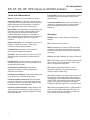
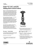
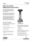
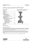
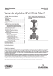
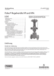
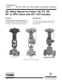
SIL Safety Manual
D103401X012
July 2010
ED, ET, EZ, HP, HPA Valves w/ 657/667 Actuator
SIL Safety Manual for Fisherr ED, ET, EZ,
HP, or HPA Valves with 657 / 667 Actuator
Purpose
Introduction
This safety manual provides information necessary
to design, install, verify and maintain a Safety
Instrumented Function (SIF) utilizing the Fisher ED,
ET, EZ, HP, or HPA valve with 657/667 actuator.
This manual provides necessary requirements for
meeting the IEC 61508 or IEC 61511 functional
safety standards.
W1916-2/IL
W6848-1
W8120A-1
ED or ET Valve
EZ Valve
Figure 1. Fisher Valve with 667 Actuator
www.Fisher.com
HP Valve with FIELDVUEt
DVC6000 Digital Valve Controller
SIL Safety Manual
ED, ET, EZ, HP, HPA Valves w/ 657/667 Actuator
Terms and Abbreviations
Safety: Freedom from unacceptable risk of harm.
Functional Safety: The ability of a system to carry
out the actions necessary to achieve or to maintain a
defined safe state for the equipment / machinery /
plant / apparatus under control of the system.
Basic Safety: The equipment must be designed and
manufactured such that it protects against risk of
injury to persons by electrical shock and other
hazards and against resulting fire and explosion.
The protection must be effective under all conditions
of the nominal operation and under single fault
condition.
Safety Assessment: The investigation to arrive at a
judgment - based on the facts - of the safety
achieved by safety-related systems.
July 2010
Fail No Effect: Failure of a component that is part of
the safety function but that has no effect on the
safety function.
Low Demand Mode: Mode, where the frequency of
demands for operation made on a safety-related
system is no greater than twice the proof test
frequency.
Acronyms
FMEDA: Failure Modes, Effects and Diagnostic
Analysis
HFT: Hardware Fault Tolerance
Fail-Safe State: State where valve actuator is
de-energized and spring is extended.
MOC: Management of Change. These are specific
procedures often done when performing any work
activities in compliance with government regulatory
authorities.
Fail Safe: Failure that causes the valve to go to the
defined fail-safe state without a demand from the
process.
PFDAVG: Average Probability of Failure on Demand
Fail Dangerous: Failure that does not respond to a
demand from the process (i.e. being unable to go to
the defined fail-safe state).
SFF: Safe Failure Fraction, the fraction of the overall
failure rate of a device that results in either a safe
fault or a diagnosed unsafe fault.
Fail Dangerous Undetected: Failure that is
dangerous and that is not being diagnosed by
automatic stroke testing.
SIF: Safety Instrumented Function, a set of
equipment intended to reduce the risk due to a
specific hazard (a safety loop).
Fail Dangerous Detected: Failure that is dangerous
but is detected by automatic stroke testing.
Fail Annunciation Undetected: Failure that does
not cause a false trip or prevent the safety function
but does cause loss of an automatic diagnostic and
is not detected by another diagnostic.
Fail Annunciation Detected: Failure that does not
cause a false trip or prevent the safety function but
does cause loss of an automatic diagnostic or false
diagnostic indication.
2
SIL: Safety Integrity Level, discrete level (one out of
a possible four) for specifying the safety integrity
requirements of the safety functions to be allocated
to the E/E/PE safety-related systems where Safety
Integrity Level 4 has the highest level of safety
integrity and Safety Integrity Level 1 has the lowest.
SIS: Safety Instrumented System – Implementation
of one or more Safety Instrumented Functions. A
SIS is composed of any combination of sensor(s),
logic solver(s), and final element(s).
SIL Safety Manual
July 2010
ED, ET, EZ, HP, HPA Valves w/ 657/667 Actuator
Related Literature
Hardware Documents:
D ANSI/ISA 84.00.01-2004 (IEC 61511 Mod.)
Functional Safety – Safety Instrumented Systems for
the Process Industry Sector
51.1:ED, Fisher ED, EAD, and EDR SlidingStem
Control Valves Bulletin: D100017X012
Fisher ED and EAD easyet Valves CL125 through
CL600 Instruction Manual: D100390X012
Device Description
51.1:ET, Fisher ET, EAT, and ETR SlidingStem
Control Valves Bulletin: D100022X012
Fisher ED single-port valves (figure 1) have cage
guiding, quick-change trim, and balanced
push-down-to-close valve plug action. Valve
configurations are as follows:
Fisher ET and EAT easyet Valves CL125 through
CL600 Instruction Manual: D100398X012
ED--Globe-style valve with metal-to-metal seating for
all general applications over a wide variety of
pressure drops and temperatures.
51.1:EZ, Fisher EZ SlidingStem Control Valve
Bulletin: D100025X012
EAD--Angle version of ED, used to facilitate piping
or in applications where a self-draining valve is
required.
Fisher EZ easyet Control Valve Instruction
Manual: D100401X012
Fisher ET single-port valves (figure 1) have cage
guiding, quick-change trim, and balanced
push-down-to-close valve plug action. Valve
configurations are as follows:
51.2:HP, Fisher HP Series Control Valves Bulletin:
D101635X012
Fisher HP and HPA Control Valves Instruction
Manual: D101634X012
Guidelines/References:
D Safety Integrity Level Selection – Systematic
Methods Including Layer of Protection Analysis,
ISBN 1-55617-777-1, ISA
D Control System Safety Evaluation and
Reliability, 2nd Edition, ISBN 1-55617-638-8, ISA
D Safety Instrumented Systems Verification,
Practical Probabilistic Calculations, ISBN
1-55617-909-9, ISA
Reference Standards
Functional Safety
D IEC 61508: 2000 Functional safety of
electrical/electronic/ programmable electronic
safety-related systems
ET--Globe-style valve with metal-to-PTFE seating
(standard for all except Cavitrol III cages) for
stringent shutoff requirements, or metal-to-metal
seating (standard for Cavitrol III cages, optional for
all others) for higher temperatures.
EAT--Angle version of ET, used to facilitate piping or
in applications which require a self-draining valve.
Fisher EZ valves (figure 1) are globe-style with
integral end connections, post guiding, and
quick-change trim. These valves are used in
chemical or hydrocarbon processing applications or
in applications that require control of nonlubricating,
viscous, or other hard-to-handle fluids.
Fisher HP Series high-pressure globe and angle
valves (figure 1) have metal seats, cage guiding,
quick change trim, and push-down-to-close valve plug
action. HPD, HPAD, HPT, and HPAT valves use
balanced valve plugs. HPS and HPAS valves use an
unbalanced valve plug. To provide a seal between
the cage and a balanced valve plug, the HPD and
HPAD valve plugs use piston rings; the HPT and
HPAT valve plugs use a pressure-assisted seal ring.
A Whisper Trim cage can be used with an HPD,
HPAD, HPS, HPAS, HPT, or HPAT valve plug. A
Cavitrol III cage can be used with an HPS, HPAS,
HPT, or HPAT valve plug.
3
SIL Safety Manual
ED, ET, EZ, HP, HPA Valves w/ 657/667 Actuator
Designing a SIF Using Fisher ED,
ET, EZ, HP, or HPA Valve
Safety Function
When the valve’s actuator is de-energized, the
actuator and valve shall move to its fail-safe position.
Depending on which configuration is specified
fail–closed or fail-open, the actuator will move the
valve plug to close off the flow path through the
valve body or open the flow path through the valve
body.
The ED, ET, EZ, HP, or HPA valve is intended to be
part of final element subsystem as defined per IEC
61508 and the achieved SIL level of the designed
function must be verified by the designer.
Environmental limits
The designer of a SIF must check that the product is
rated for use within the expected environmental
limits. Refer to the ED, ET, EZ, or HP and HPA valve
product bulletin for environmental limits.
Application limits
The materials of construction of ED, ET, EZ, HP, or
HPA valves are specified in the product bulletins. A
range of materials are available for various
applications. The serial card will indicate what the
materials of construction are for a given valve. It is
especially important that the designer check for
material compatibility considering on-site chemical
contaminants and environmental conditions. If the
ED, ET, EZ, HP, or HPA valve is used outside of the
application limits or with incompatible materials, the
reliability data provided becomes invalid.
July 2010
time. The PVST must be performed 10 times more
often than an expected demand in order for credit to
be given for this test.
Design Verification
A detailed FMEDA report is available from Emerson
Process Management. This report details all failure
rates and failure modes as well as the expected
lifetime.
The achieved SIL of an entire SIF design must be
verified by the designer via a calculation of PFDAVG
considering architecture, proof test interval, proof
test effectiveness, any automatic diagnostics,
average repair time and the specific failure rates of
all products included in the SIF. Each subsystem
must be checked to assure compliance with
minimum HFT requirements.
When using an ED, ET, EZ, HP, or HPA valve in a
redundant configuration, a common cause factor of
at least 5% should be included in the Safety Integrity
calculations.
The failure rate data listed in the FMEDA report is
only valid for the useful lifetime of an ED, ET, EZ,
HP, or HPA valve. The failure rates will increase
after this time period. Reliability calculations based
on the data listed in the FMEDA report for mission
times beyond the useful lifetime may yield results
that are too optimistic, i.e. the calculated Safety
Integrity Level will not be achieved.
SIL Capability
Systematic Integrity
Diagnostic Response Time
The ED, ET, EZ, HP, or HPA valve does not perform
any automatic diagnostic functions by itself and
therefore it has no diagnostic response time of its
own. However, automatic diagnostics of the final
control subsystem may be performed such as Partial
Valve Stroke Testing (PVST). This typically will
exercise the valve over a small percentage of its
normal travel without adversely affecting the flow
through the valve. If any failures of this PVST are
automatically detected and annunciated, the
diagnostic response time will be the PVST interval
4
Figure 2. exida SIL 3 Capable
The product has met manufacturer design process
requirements of SIL 3. These are intended to
achieve sufficient integrity against systematic errors
of design by the manufacturer. A SIF designed with
this product must not be used at a SIL level higher
than stated without “prior use” justification by the end
SIL Safety Manual
ED, ET, EZ, HP, HPA Valves w/ 657/667 Actuator
July 2010
user or diverse technology redundancy in the
design.
Random Integrity
The ED, ET, EZ, HP, or HPA valves are classified as
Type A devices according to IEC 61508, having a
hardware fault tolerance of 0. The complete final
element subsystem, with a Fisher valve as the final
control element, will need to be evaluated to
determine the Safe Failure Fraction of the
subsystem. If the SFF for the entire final element
subsystem is between 60% and 90%, a design can
meet SIL 2 @ HFT=0.
Safety Parameters
For detailed failure rate information refer to the
Failure Modes, Effects and Diagnostic Analysis
Report for the ED, ET, EZ, HP, or HPA valve.
Connection of the Fisher ED, ET, EZ,
HP, or HPA Valve to the SIS
Logic-solver
The final element subsystem (consisting of a
positioner, actuator, and ED, ET, EZ, HP, or HPA
valve) is connected to the safety rated logic solver
which is actively performing the Safety Function as
well as any automatic diagnostics designed to
diagnose potentially dangerous failures within the
ED, ET, EZ, HP, or HPA valve , actuator and any
other final element components, (i.e. Partial Valve
Stroke Test).
subsystem needs to be sized properly to assure that
the response time is less than the required process
safety time. The ED, ET, EZ, HP, or HPA valve will
move to its safe state in less than the required SIF’s
safety time under the specified conditions.
All SIS components including the ED, ET, EZ, HP, or
HPA valve must be operational before process
start-up.
The user shall verify that the ED, ET, EZ, HP, or
HPA valve is suitable for use in safety applications.
Personnel performing maintenance and testing on
the ED, ET, EZ, HP, or HPA valve shall be
competent to do so.
Results from the proof tests shall be recorded and
reviewed periodically.
The useful life of the ED, ET, EZ, HP, or HPA valve
is discussed in the Failure Modes, Effects and
Diagnostic Analysis Report for the Fisher ED, ET,
EZ, HP, or HPA valve.
Installation and Commissioning
Installation
The Fisher ED, ET, EZ, HP, or HPA valve must be
installed per standard practices outlined in the
appropriate instruction manual.
The environment must be checked to verify that
environmental conditions do not exceed the ratings.
General Requirements
The system’s response time shall be less than
process safety time. The final control element
The ED, ET, EZ, HP, or HPA valve must be
accessible for physical inspection.
Table 1. Recommended Full Stroke Proof Test
Step
Action
1
Bypass the safety function and take appropriate action to avoid a false trip.
2
Interrupt or change the signal/supply to the actuator to force the actuator and valve to perform a full stroke to the Fail-Safe state and
confirm that the Safe State was achieved and within the correct time.
3
Restore the supply/signal to the actuator and confirm that the normal operating state was achieved.
4
Inspect the ED, ET, EZ, HP, or HPA valve and the other final control element components for any leaks, visible damage or
contamination.
5
Record the test results and any failures in your company’s SIF inspection database.
6
Remove the bypass and restore normal operation.
5
SIL Safety Manual
ED, ET, EZ, HP, HPA Valves w/ 657/667 Actuator
Physical Location and Placement
The Fisher ED, ET, EZ, HP, or HPA valve shall be
accessible with sufficient room for the actuator,
pneumatic connections, and any other components
of the final control element. Provisions shall be made
to allow for manual proof testing.
Pneumatic piping to the actuator shall be kept as
short and straight as possible to minimize the airflow
restrictions and potential clogging. Long or kinked
pneumatic tubes may also increase the valve
closure time.
The ED, ET, EZ, HP, or HPA valve shall be mounted
in a low vibration environment. If excessive vibration
can be expected special precautions shall be taken
to ensure the integrity of pneumatic connectors or
the vibration should be reduced using appropriate
damping mounts.
July 2010
maintain the required Safety Integrity of the Safety
Instrumented Function.
The proof test shown in table 1 is recommended.
The results of the proof test should be recorded and
any failures that are detected and that compromise
functional safety should be reported to Emerson
Process Management. The suggested proof test
consists of a full stroke of the ED, ET, EZ, HP, or
HPA valve.
The person(s) performing the proof test of an ED,
ET, EZ, HP, or HPA valve should be trained in SIS
operations, including bypass procedures, valve
maintenance and company Management of Change
procedures. No special tools are required.
Repair and replacement
Repair procedures in the appropriate valve
instruction manual must be followed.
Operation and Maintenance
Suggested Proof Test
The objective of proof testing is to detect failures
within an ED, ET, EZ, HP, or HPA valve that are not
detected by any automatic diagnostics of the
system. Of main concern are undetected failures
that prevent the Safety Instrumented Function from
performing its intended function.
The frequency of proof testing, or the proof test
interval, is to be determined in reliability calculations
for the Safety Instrumented Functions for which an
ED, ET, EZ, HP, or HPA valve is applied. The proof
tests must be performed more frequently than or as
frequently as specified in the calculation in order to
6
Manufacturer Notification
Any failures that are detected and that compromise
functional safety should be reported to Emerson
Process Management. Please contact Emerson
Process Management customer service or your local
Emerson Process Management service
representative.
Status of the Document
Releases
Version History:
(Version, Status, Date)
SIL Safety Manual
ED, ET, EZ, HP, HPA Valves w/ 657/667 Actuator
July 2010
Appendix A
Start-Up Checklist
Sample Startup Checklist
The following checklist may be used as a guide to
employ the ED, ET, EZ, HP, or HPA valve in a safety
critical SIF compliant to IEC61508.
This appendix provides a Sample Start-up Checklist
for a Fisher ED, ET, EZ, HP, or HPA valve. A
start-up checklist will provide guidance during the
final control element’s employment.
#
Activity
Result
Verified
By
Date
Design
Target Safety Integrity Level and PFDAVG determined
Correct valve mode chosen (Fail-closed, Fail-open)
Design decision documented
Pneumatic compatibility and suitability verified
SIS logic solver requirements for valve tests defined and
documented
Routing of pneumatic connections determined
SIS logic solver requirements for partial stroke tests defined and
documented
Design formally reviewed and suitability formally assessed
Implementation
Physical location appropriate
Pneumatic connections appropriate and according to applicable
codes
SIS logic solver valve actuation test implemented
Maintenance instructions for proof test released
Verification and test plan released
Implementation formally reviewed and suitability formally assessed
Verification and Testing
Electrical connections verified and tested
Pneumatic connection verified and tested
SIS logic solver valve actuation test verified
Safety loop function verified
Safety loop timing measured
Bypass function tested
Verification and test results formally reviewed and suitability formally
assessed
Maintenance
Tubing blockage / partial blockage tested
Safety loop function tested
7
SIL Safety Manual
ED, ET, EZ, HP, HPA Valves w/ 657/667 Actuator
July 2010
Note
Neither Emerson, Emerson Process
Management, nor any of their affiliated
entities assume responsibility for the
selection, use, or maintenance of any
product. Responsibility for the
selection, use, and maintenance of any
product remains with the purchaser
and end user.
Fisher, FIELDVUE, and easye are marks owned by one of the companies in the Emerson Process Management business division of Emerson
Electric Co. Emerson Process Management, Emerson, and the Emerson logo are trademarks and service marks of Emerson Electric Co. All other
marks are the property of their respective owners.
The contents of this publication are presented for informational purposes only, and while every effort has been made to ensure their accuracy, they
are not to be construed as warranties or guarantees, express or implied, regarding the products or services described herein or their use or
applicability. All sales are governed by our terms and conditions, which are available upon request. We reserve the right to modify or improve the
designs or specifications of such products at any time without notice. Neither Emerson, Emerson Process Management, nor any of their affiliated
entities assume responsibility for the selection, use or maintenance of any product. Responsibility for proper selection, use, and maintenance of
any product remains solely with the purchaser and end user.
Emerson Process Management
Marshalltown, Iowa 50158 USA
Sorocaba, 18087 Brazil
Chatham, Kent ME4 4QZ UK
Dubai, United Arab Emirates
Singapore 128461 Singapore
www.Fisher.com
8
EFisher
Controls International LLC 2010; All Rights Reserved