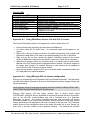
1
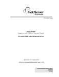
A Sierra Monitor Company
Driver Manual
(Supplement to the FieldServer Instruction Manual)
FS-8700-104 ControlNet X30 Driver
APPLICABILITY & EFFECTIVITY
Effective for all systems manufactured after May 1, 2001
Driver Version:
1.01
Document Revision: 7
FS-8700-104_ControlNet_X30 Manual
Table of Contents
TABLE OF CONTENTS
1.
2.
CONTROLNET X30 DESCRIPTION .................................................................................3
DRIVER SCOPE OF SUPPLY...........................................................................................4
2.1.
Supplied by FieldServer Technologies for this driver ...................................................4
2.2.
Provided by the Supplier of 3rd Party Equipment ..........................................................4
2.2.1. Required 3rd Party Software ......................................................................................4
2.2.2. Required 3rd Party Configuration ...............................................................................4
2.2.3. Optional Items ...........................................................................................................4
3.
3.1.
4.
HARDWARE CONNECTIONS ..........................................................................................5
Hardware Connection Tips / Hints ................................................................................5
CONFIGURING THE FIELDSERVER AS A CONTROLNET SERVER ............................6
4.1.
ControlNet Settings ......................................................................................................6
4.2.
Server Side Connection Descriptors.............................................................................7
4.3.
Server Side Node Descriptors ......................................................................................7
4.4.
Server Side Map Descriptors........................................................................................8
4.4.1. FieldServer Specific Map Descriptor Parameters .....................................................8
4.4.2. Driver Specific Map Descriptor Parameters ..............................................................8
4.4.3. Map Descriptor Example. ..........................................................................................9
APPENDIX A. ADVANCED TOPICS ......................................................................................10
Appendix A.1. ControlNet X30 LED indicators .....................................................................10
Appendix A.2. Using RSNetWorx Version 1.06 with PLC-5 scanner....................................11
Appendix A.3. Using RSLogix 5000 for network configuration .............................................11
APPENDIX B. DRIVER NOTES ..............................................................................................13
Appendix B.1. Setting the FieldServer’s ControlNet MAC ID ...............................................13
Appendix B.2. Using the Network Access Port.....................................................................13
FieldServer Technologies 1991 Tarob Court Milpitas, California 95035 USA Web:www.fieldserver.com
Tel: (408) 262-2299 Fax: (408) 262-9042 Toll_Free: 888-509-1970 email: [email protected]
FS-8700-104_ControlNet_X30 Manual
1.
Page 3 of 13
ControlNet X30 Description
The FieldServer ControlNet X30 driver can be used to emulate a single slave station on a
ControlNet network. ControlNet scanners can open a connection of up to 450 Bytes in each
direction to the FieldServer. Data transfers are via Scheduled Communication and therefore the
FieldServer has to be scheduled on the ControlNet network using a Network Configuration Tool
such as RSNetWorx or RSLogix. The minimum supported network update time (NUT) is 5 ms.
Connection to the ControlNet network is via two standard BNC connector ports. The connection
may be to either one or both of the ControlNet ports. A connection to both ports provides dual
redundant operation. A Network Access Port (NAP) is also provided for the temporary
connection of a Network Configuration Tool.
Max Nodes Supported
FieldServer Mode Nodes Comments
Server
1
The FieldServer can only emulate one ControlNet Slave station
FieldServer Technologies 1991 Tarob Court Milpitas, California 95035 USA Web:www.fieldserver.com
Tel: (408) 262-2299 Fax: (408) 262-9042 Toll_Free: 888-509-1970 email: [email protected]
FS-8700-104_ControlNet_X30 Manual
2.
Page 4 of 13
Driver Scope of Supply
2.1.
Supplied by FieldServer Technologies for this driver
FieldServer Technologies
PART #
FS-8700-104
X30-ControlNet
Description
Driver Manual.
Anybus ControlNet Card
Provided by the Supplier of 3rd Party Equipment
2.2.
2.2.1.
Required 3rd Party Software
RSNetWorx, RSLogix or another Network Scheduling Tool.
2.2.2.
Required 3rd Party Configuration
Connection to a properly terminated ControlNet network.
2.2.3.
PART #
-
Optional Items
Vendor/Manufacturer
HMS-Networks
Description
ControlNet eds file
FieldServer Technologies 1991 Tarob Court Milpitas, California 95035 USA Web:www.fieldserver.com
Tel: (408) 262-2299 Fax: (408) 262-9042 Toll_Free: 888-509-1970 email: [email protected]
FS-8700-104_ControlNet_X30 Manual
3.
Page 5 of 13
Hardware Connections
The FieldServer is connected to the ControlNet network as shown in the connection drawing
below.
3.1.
Hardware Connection Tips / Hints
Use the recommended network cable and terminators as specified by the ControlNet
network organization and/or the manufacturer of your network equipment.
FieldServer Technologies 1991 Tarob Court Milpitas, California 95035 USA Web:www.fieldserver.com
Tel: (408) 262-2299 Fax: (408) 262-9042 Toll_Free: 888-509-1970 email: [email protected]
FS-8700-104_ControlNet_X30 Manual
4.
Page 6 of 13
Configuring the FieldServer as a ControlNet Server
For a detailed discussion on FieldServer configuration, please refer to the FieldServer
Configuration Manual. The information that follows describes how to expand upon the factory
defaults provided in the configuration files included with the FieldServer (See “.csv” files on the
driver CD).
This section documents and describes the parameters necessary for configuring the FieldServer
to communicate with a ControlNet Client/Scanner.
The configuration file tells the FieldServer about its interfaces, and the routing of data required.
In order to enable the FieldServer for ControlNet communications, the driver independent
FieldServer buffers need to be declared in the “Data Arrays” section, the FieldServer virtual
node(s) needs to be declared in the “Server Side Nodes” section, and the data to be provided to
the clients needs to be mapped in the “Server Side Map Descriptors” section. Details on how to
do this can be found below.
Note that in the tables, * indicates an optional parameter, with the bold legal value being the
default.
4.1.
ControlNet Settings
Section Title
FieldServer
Column Title
System_Station_Address*
Function
ControlNet MAC ID of the FieldServer
Legal Values
1-99
Note:
The ControlNet MAC ID can also be set via the two rotary switches on the side of the
FieldServer. These switches should be set to zero or to the same value as
System_Station_Address
in
the
configuration
file.
Alternatively
the
System_Station_Address parameter should be eliminated from the configuration file.
Failing to do so, will cause a warning LED to flash although the MAC ID from the
configuration file will still be used.
Example
// FieldServer
FieldServer
Title,
CN_Test,
System_Station_Address
5
FieldServer Technologies 1991 Tarob Court Milpitas, California 95035 USA Web:www.fieldserver.com
Tel: (408) 262-2299 Fax: (408) 262-9042 Toll_Free: 888-509-1970 email: [email protected]
FS-8700-104_ControlNet_X30 Manual
4.2.
Page 7 of 13
Server Side Connection Descriptors
Section Title
Connections
Column Title
Adapter
Function
Adapter Name
Legal Values
ControlNet
Example
//
Server Side Connections
Connections
Adapter
ControlNet
4.3.
Server Side Node Descriptors
Section Title
Nodes
Column Title
Node_Name
Protocol
Function
Provide name for node
Specify protocol used
Legal Values
Up to 32 alphanumeric characters
Anybus ControlNet
Example
//
Server Side Nodes
Nodes
Node_Name,
CN5,
Protocol
Anybus ControlNet
FieldServer Technologies 1991 Tarob Court Milpitas, California 95035 USA Web:www.fieldserver.com
Tel: (408) 262-2299 Fax: (408) 262-9042 Toll_Free: 888-509-1970 email: [email protected]
FS-8700-104_ControlNet_X30 Manual
4.4.
Page 8 of 13
Server Side Map Descriptors
4.4.1.
FieldServer Specific Map Descriptor Parameters
Column Title
Function
Map_Descriptor_Name Name of this Map Descriptor
Data_Array_Name
Data_Array_Offset
Function of
Descriptor
Function
4.4.2.
Name of Data Array where
data is to be stored in the
FieldServer
Starting location in Data
Array
Server
Map
Legal Values
Up to 32 alphanumeric
characters
One of the Data Array names
from “Data Array” section
above
0 to maximum specified in
“Data Array” section above
RDBC -Reads data from the
local input buffer
WRBC -Writes data to the
local output buffer
Driver Specific Map Descriptor Parameters
Column Title
Node_Name
CNT_Data_Type
Address
Length
Function
Legal Values
One of the node names
Name of Node
specified in “Server Node
Descriptor” above
BYTE, WORD, DWORD,
Data Type of local buffer
BOOL
RDBC: 0 – 449
Byte offset into local buffer
WRBC: 4 – 453
BYTE: 1 – 450
Number of CNT_Data_Type WORD: 1 – 225
items in local buffer
DWORD: 1 – 112
BOOL: 1 – 3600
FieldServer Technologies 1991 Tarob Court Milpitas, California 95035 USA Web:www.fieldserver.com
Tel: (408) 262-2299 Fax: (408) 262-9042 Toll_Free: 888-509-1970 email: [email protected]
FS-8700-104_ControlNet_X30 Manual
4.4.3.
//
Page 9 of 13
Map Descriptor Example.
Client side Map Descriptors
Map_Descriptors
Map_Descriptor_Name,
Get_Data,
Put_Data,
Data_Array_Name,
Input_Data,
Output_Data,
Read function map
descriptor gets data
from the ControlNet
network and stores it
in the Input_Data
data array.
Data_Array_Offset,
0,
0.
Function,
RDBC,
WRBC,
Write function map
descriptor
puts
data
from
the
Output_Data data
array onto the
ControlNet
network.
Node_Name,
CN5,
CN5,
CNT_Data_Type,
WORD,
WORD,
Note the start
address for the
output buffer is
4.
Addresses
0-3 are not
available.
Address,
0,
4,
Length,
225,
225,
Scan_Interval
1s
1s
Note that each address
refers to an individual
local input and output
buffer. Each buffer can
contain up to 450 bytes.
FieldServer Technologies 1991 Tarob Court Milpitas, California 95035 USA Web:www.fieldserver.com
Tel: (408) 262-2299 Fax: (408) 262-9042 Toll_Free: 888-509-1970 email: [email protected]
FS-8700-104_ControlNet_X30 Manual
Page 10 of 13
Appendix A. Advanced Topics
Appendix A.1. ControlNet X30 LED indicators
LED 1 – Module status
Color
Green
Green
Red
Red
Frequency
Flashing
Steady on
Flashing
Steady on
Description
Module is waiting for initialisation
Module is initialised
Minor fault, MacID has been changed after initialisation, etc.
Major fault, module must be restarted
LED 2 – LED Channel A
Color
Red/Green
Frequency
-
Description
See Channel LEDs below
LED 3 – LED Channel B
Color
Red/Green
Frequency
-
Description
See Channel LEDs below
LED 4 – Module Owned
Color
Green
Off
Frequency
Steady on
-
Description
A connection is opened against the ControlNet module
No connection is opened
FieldServer Technologies 1991 Tarob Court Milpitas, California 95035 USA Web:www.fieldserver.com
Tel: (408) 262-2299 Fax: (408) 262-9042 Toll_Free: 888-509-1970 email: [email protected]
FS-8700-104_ControlNet_X30 Manual
Page 11 of 13
Channel LEDs
Channel LEDs
A and B, steady off
A and B, steady red
A and B, alternating red/green
A and B, flashing red
A or B, steady off
A or B, steady green
A or B, flashing green
A or B, flashing red
A or B, flashing red/green
Description
Module is not initialised
Faulted unit, must be restarted or repaired
Selftest of bus controller
Incorrect node configuration, duplicate MacID, etc.
Channel is disabled, depending on network configuration
Normal operation of channel
Temporary errors (node will self correct) or node is not
configured to go online
Media fault or no other nodes on the network
Incorrect network configuration
Appendix A.2. Using RSNetWorx Version 1.06 with PLC-5 scanner
The Anybus ControlNet module is not supported for versions earlier than 1.06.
•
•
•
•
•
•
Ensure all nodes are physically connected and start RSNetworx.
Go online (check the Go online box) - all connected nodes should appear on the
screen.
Right click on the PLC5 node and choose ControlNet configuration. The program now
launches the Map Editing Tool used to set up data mapping in the PLC-5 processor.
Right click on the line that contains the Anybus ControlNet module (in the current
version of RSNetworx displayed as Any-BusDT) and choose Insert device connection.
When the line changes to blue, the connection size in, connection size out and to which
address in the PLC the data shall be mapped should be entered. The data is mapped to
the Integer area (N-area). For example, 50 bytes in each direction can be mapped so
now 25 words in and 25 words out can be chosen.
Save the configuration, switch the PLC key to run and the data is transferred to/from the
PLC data table at the specified address.
Appendix A.3. Using RSLogix 5000 for network configuration
RSLogix is a programming and configuration tool from Rockwell automation. The information
included in this section is based on an entry in the Rockwell Automation Support Library and
can be accessed at:
www5.software.rockwell.com/support/knowbase.nsf/9dc47c2a86607f2d86256365001169f5/
bb01b77898478eca852568ef005e0b52?OpenDocument
RSLogix 5000 Version 2.25 and higher versions have a generic profile called
CONTROLNET- MODULE which is applicable to devices that connect directly to ControlNet,
such as the 1203-CN1 communications card with a Rockwell drive or a Schneider
Momentum I/O device. The Anybus ControlNet card also uses this profile. All Anybus
ControlNet-enabled I/O will use the same assembly instance numbers, but the data size will
change depending on the application and must be relayed to the end user. The ControlNet
module does not use configuration data so the length should be left at zero, though you
must enter a non-zero number for the assembly instance. The following list provides
FieldServer Technologies 1991 Tarob Court Milpitas, California 95035 USA Web:www.fieldserver.com
Tel: (408) 262-2299 Fax: (408) 262-9042 Toll_Free: 888-509-1970 email: [email protected]
FS-8700-104_ControlNet_X30 Manual
Page 12 of 13
information on the settings for the CONTROLNET-MODULE profile with AnyBus-S enabled
devices.
Name:
Description:
Comm Format:
Node:
Input Assembly Instance:
Size:
(choose a unique name for this module)
(self-explanatory and optional)
Select ‘Data - INT’
Select the ControlNet node number for this device
100
Varies with how the module is intialized
Note: The ControlNet module uses a ControlNet 32-bit run/idle header, so the actual data
from the module will always start with word 2 (the third word) of the data. The first 2 words,
at 16 bits each, are the ControlNet run/idle header. If you want to mask off the run/idle
header for clarity, create a user defined type with 2 members - HEADER, type DINT; and
DATA, type INT with ‘input assembly size - 2’. Copy the data from the actual input tag to a
tag of this structure, and then you can reference the structure's DATA member using the
element numbers in your documentation.
Output Assembly Instance:
Size:
Configuration Assembly Instance:
Size:
150
Varies with how the module is initialized
1
0
Note: There will always be a configuration tag of type AB:ControlNet_MODULE:C:0 created
for this module, which has one member called Data, of type SINT[400]. This SINT[400] tag
is created regardless of the configuration size, which can range from 0 to 400 bytes (SINTs).
Since a data size of zero is specified, no data will be sent to the module.
FieldServer Technologies 1991 Tarob Court Milpitas, California 95035 USA Web:www.fieldserver.com
Tel: (408) 262-2299 Fax: (408) 262-9042 Toll_Free: 888-509-1970 email: [email protected]
FS-8700-104_ControlNet_X30 Manual
Page 13 of 13
Appendix B. Driver Notes
Appendix B.1. Setting the FieldServer’s ControlNet MAC ID
The MAC ID can be set in the FieldServer’s CSV file using the System_Station_Address,
(refer to Section 4.1), or it can be set with the two rotary switches as indicated on the
connection diagram. The left switch selects the left decimal digit and the right switch the
right decimal digit of the MAC ID.
Note that the software setting with the System_Station_Address overrides the hardware
setting with the rotary switches. Set the rotary switches to zero or to the same value as in
the System_Station_Address to prevent the warning LED from flashing. A mismatch will still
result in the software setting being used.
Appendix B.2. Using the Network Access Port
The Network Access Port (NAP) should only be used temporarily to connect a network
configuration tool. It must not be used to connect to the main ControlNet network.
FieldServer Technologies 1991 Tarob Court Milpitas, California 95035 USA Web:www.fieldserver.com
Tel: (408) 262-2299 Fax: (408) 262-9042 Toll_Free: 888-509-1970 email: [email protected]