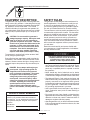
1
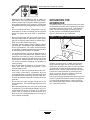
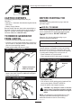
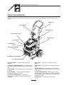
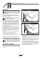
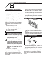
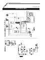
GENERAC MEGA 2500 Extended Life Generator Owner’s Manual Danger: This generator is designed for outdoor use only. Do not use this generator inside any building or enclosure including the generator compartment of a recreational vehicle (RV). Fire or an explosion may result. No user performed modifications, including venting of exhaust and/or cooling ventilation, will eliminate the danger. Also, allow at least two feet of clearance on all sides of the generator even while operating the unit outdoors. Danger: If this unit is used for backup power in the event of a utility power failure, the following step must be taken: Before connecting the generator to an electrical system, open the main circuit breaker or main switch serving the system, to isolate the generator system from the electric utility. Failure to isolate the generator and utility systems may result in damage to the generator and may also result in injury or death to electric utility workers, due to a backfeed of electrical energy. Model No.10160 (2000 Watt AC Generator) Part No. B1761 (Revision 0 9/2/97) This symbol points out important safety instructions, which, if not followed, could endanger the personal safety and/or property of yourself and others. Read and follow all instructions in the manual before attempting to operate this unit. C A Generac Mega 2500 Extended Life Generator R E N E G EQUIPMENT DESCRIPTION SAFETY RULES This generator is an engine-driven, revolving field, alternating current (AC) generator. It was designed to supply electrical power for operating compatible electrical lighting, appliance, tool and motor loads. This manual contains information for a generator that operates 120 volt, single phase, 60Hz devices that require up to 2000 watts (2.0 kW) of power that pull up to 15 amps at 120 volts. This generator set was designed and manufactured for specific applications. Do not attempt to modify the unit or use it for any application it was not designed for. If you have any questions about your generators application, ask your Dealer/Distributor or consult the factory. The manufacturer could not possibly anticipate every circumstance that might involve a hazard. For that reason warnings in the Manual and warnings on tags or decals affixed to the unit are not all-inclusive. If you intend to handle, operate or service the unit by a procedure or method not specifically recommended by the manufacturer, first make sure that such a procedure or method will not render this equipment unsafe or pose a threat to you and others. Read this manual carefully and become familiar with your generator set. Know its applications, its limitations and any hazards involved. CAUTION: Do not exceed the generators wattage/amperage capacity. Add up the rated watts of all devices you are connecting to generator receptacles at one time. This total should not be greater than 2000 watts for this generator. In most cases rated watts of the electrical device can be found on the device nameplate. If the device nameplate gives only volts and amps, multiply volts times amps to obtain watts (volts x amps = watts). WARNING: The generators revolving field is driven at about 3600 rpm by a single-cylinder engine. Every effort has been expended to make sure that the information in this manual is both accurate and current. However, Generac reserves the right to change, alter or otherwise improve the product at any time without prior notice. The engine exhaust from this product contains chemicals known to the State of California to cause cancer, birth defects, or other reproductive harm. The generator produces a very powerful voltage that can cause extremely dangerous electrical shock. Avoid contact with bare wires, terminals, etc. Never permit any unqualified person to operate or service the generator. Never handle any kind of electrical cord or device while standing in water, while barefoot or while hands or feet are wet. Dangerous electrical shock will result. The National Electric Code requires the frame and external electrically conductive parts of generator be properly connected to an approved earth ground. Local electrical codes may also require proper grounding of the generator. Consult with a local electrician for grounding requirements in your area. Use a ground fault circuit interrupter in any damp or highly conductive area (such as metal decking or steel work). Do not use any worn, bare, frayed or otherwise damaged electrical cord sets with the generator. Using any defective cord set may result in electrical shock or damage to equipment and/or property. Operate generator only on level surfaces and where it will not be exposed to excessive moisture, dirt, dust or corrosive vapors. DANGER: Do not tamper with engine governed speed. High operating speeds are dangerous and increase risk of personal injury or damage to equipment. The generator supplies correct rated frequency and voltage only when running at proper governed speed. Incorrect frequency and/or voltage can damage some connected electrical loads. Operating at excessively low speeds imposes a heavy load at such reduced speeds, when adequate engine power is not available, and may short engine life. MODEL & SERIAL NUMBERS In the spaces provided below, insert the Model and Serial numbers of your generator. Retain these numbers for future reference. You can find Model and Serial numbers on the generator data plate, along with other important information. Model Number Serial Number Extended Life Generator 2 C A Generac Mega 2500 Extended Life Generator R E N E G GROUNDING THE GENERATOR Gasoline is highly FLAMMABLE and its vapors are EXPLOSIVE. Do not permit smoking, open flames, sparks or heat in the vicinity while handling gasoline. Avoid spilling gasoline on a hot engine. Comply with all regulations requiring storage and handling of gasoline. Do not overfill the fuel tank. Always allow room for fuel expansion. If tank is overfilled, fuel can overflow onto a hot engine and cause FIRE or an EXPLOSION. Never store generator with fuel in tank where gasoline vapors might reach an open flame or spark or pilot light (as on a furnace, water heater or clothes dryer). FIRE or an EXPLOSION might result. Generator exhaust gases contain DEADLY carbon monoxide gas. This dangerous gas, if breathed in sufficient concentrations, can cause unconsciousness or even death. Operate this equipment only in the open air where adequate ventilation is available. The engine-generator requires an adequate flow of cooling air for its continued proper operation. Never operate the unit inside any room or enclosure where the free flow of cooling air into and out of the unit might be obstructed. Without sufficient cooling air flow, the unit quickly overheats, damaging the generator or nearby property. Allow at least 2 feet of clearance on all sides of generator, even while operating unit outdoors, or you could damage the unit. Never start, or stop, the engine-generator with electrical loads connected to receptacles with the connected devices turned ON. Start the engine and let it stabilize before connecting electrical loads. Disconnect all electrical loads before shutting down the generator. Do not insert any object through cooling slots of the engine-generator. You could damage the unit or injure yourself. Never operate generator (a) in rain; (b) in any enclosed compartment; (c) if engine speed changes; (d) if connected electrical devices overheat; (e) if electrical output is lost; (f) if engine or generator sparks; (g) if flame or smoke is observed while unit is running; (h) if unit vibrates excessively. The National Electric Code requires the frame and external electrically conductive parts of generator be properly connected to approved earth ground. Local electrical codes may also require proper grounding of the unit. For that purpose, a GROUNDING WING SCREW (Figure 1) is provided on the cradle frame. Figure 1 Location of Grounding Wing Nut Generally, connecting a No. 12 AWG (American Wire Gauge) stranded copper wire to the grounding wing screw and to an earth-driven copper or brass grounding rod (electrode) provides adequate protection against electrical shock. However, local codes may vary widely. Consult with a local electrician for grounding requirements in your area. Be sure to keep the ground wire attached while you connect the electrode. Properly grounding the generator helps prevent electrical shock if a ground fault conditions exists in the generator or in connected electrical devices. Proper grounding also helps dissipate static electricity, which often builds up in ungrounded devices. Extended Life Generator 3 C A Generac Mega 2500 Extended Life Generator R E N E G CARTON CONTENTS BEFORE STARTING THE ENGINE The following parts are shipped loose with your Generator: Main Unit Generator with wheels and guide handle Wire Form Battery Charge Cables Become familiar with each piece before assembling the Generator. Check all contents against the illustration on Page 5. If any parts are missing or damaged, call the Generator Helpline at 1-800-2701408. Perform the following tasks before trying to start the generator engine: ADD OIL TO ENGINE Note: When adding oil to the engine crankcase in the future, use only high quality detergent oil rated with API service classification SF and SG rated SAE 30 weight. Use no special additives. DO NOT USE SAE 10W-40. TO REMOVE GENERATOR FROM CARTON Select the oils viscosity grade according to your expected operating temperature. Remove loose parts included with Generator. Slice two corners at guide handle end of carton from top to bottom so the panel can be folded down flat, then remove all packing material. Raise guide handle and secure in place. colder 32°F 5W30 warmer 10W30 Although multi-viscosity oils (5W30, 10W30, etc.) improve starting in cold weather, these multi-viscosity oils will result in increased oil consumption when used above 32°F. Check your engine oil level more frequently to avoid possible damage from running low on oil. Place Generator on a level surface Clean area around oil fill and remove oil dipstick. Figure 2 Raise Guide Handle Loosen knobs to raise handle Figure 4 Remove Oil Dipstick Dipstick Tighten knobs when handle is straight. Remove the unit by rolling it out the opening in the carton, then check carton for additional loose parts. Insert the wire support. Figure 3 Insert Wire Support Wipe dipstick clean. Pour oil into the oil fill opening until oil reaches FULL mark on the dipstick. DO NOT OVERFILL. Install oil dipstick, hand tighten securely. CAUTION: Any attempt to crank or start the engine before it has been properly serviced with the recommended oil results in an engine failure. NOTE: The generators revolving field rides on a prelubricated and sealed ball bearing that requires no additional lubrication for the life of the bearing. Extended Life Generator 4 C A Generac Mega 2500 Extended Life Generator R E N E G KNOW YOUR GENERATOR Read this owners manual and safety rules before operating your generator. Compare the illustrations with your generator, to familiarize yourself with the locations of various controls and adjustments. Save the manual for future reference. Wire Form Recoil Starter 5.5 H.P. Engine Choke Control Lever Oil Drain Plug Air Cleaner On/Off Switch 120 Volts Receptacles 15AMP AC Circuit Breaker 12 Volts DC Receptacle RECOIL STARTER Used for starting the engine manually. 15-AMP AC CIRCUIT BREAKER Protects the generator against electrical overload. Breaker is push to reset type. AIR CLEANER Filters intake air as it is drawn through the engine. 5.5 H.P. ENGINE Provides the power needed to generate 2000 watts of AC output. 12VOLT D.C. RECEPTACLE Recharge a discharged 12 volt automotive type battery through this receptacle. FUEL TANK Tank holds 1.6 quarts of unleaded gasoline. WIRE FORM Use the wireform to hold your extension cords. ON/OFF SWITCH Set this switch to ON to before pulling the recoil handle. Set this switch to OFF to stop a running engine. 120 VOLT RECEPTACLES May be used to supply electrical power for the operation of 120 volts at 15 amps ac, single phase, 60 Hz, ac electrical lighting, appliance, tool and motor loads. Oil Drain Plug Use this plug to drain the oil. Extended Life Generator 5 C A Generac Mega 2500 Extended Life Generator R E N E G ADD FUEL Figure 5 Choke Control Lever Choke Control Lever DANGER! NEVER fill fuel tank indoors. NEVER fill fuel tank when engine is running or hot. DO NOT light a cigarette or smoke when filling the fuel tank. Use regular UNLEADED gasoline with the generator engine. Regular leaded gasoline may also be used if UNLEADED is not available. CAUTION: Do not overfill the fuel tank. Always allow room for fuel expansion. IMPORTANT: It is important to prevent gum deposits from forming in essential fuel system parts such as the carburetor, fuel filter, fuel hose or tank during storage. Also, experience indicates that alcohol-blended fuels (called gasohol, ethanol or methanol) can attract moisture which leads to separation and formation of acids during storage. Acidic gas can damage the fuel system of an engine while in storage. To avoid engine problems, the fuel system should be emptied before storage of 30 days or longer. Drain the gas tank, start the engine and let it run until the fuel lines and carburetor are empty. Use fresh fuel next season. See Storage Instructions on page 10 for additional information. Never use engine or carburetor cleaner products in the fuel tank or permanent damage may occur. Clean area around fuel fill cap, remove cap. Add UNLEADED regular gasoline, slowly, to fuel tank. Install fuel cap and wipe up any spilled gasoline. Move ON/OFF SWITCH to ON position. Figure 6 On/Off Switch On/Off Switch If engine is warm, close choke only part way or leave it fully open. A warm engine needs less choking than a cold engine. Grasp starter grip and pull slowly until you feel some resistance. Let rope return slowly. Then pull cord out with rapid full arm stroke. Let rope return slowly. Do not let rope snap back against starter. If engine hunts or falters after starting, apply choke until engine begins running smoothly. Then return the choke to the open position. If engine continues to hunt, you may need to have the carburetor adjusted. See Engine Owners Manual. OPERATING THE GENERATOR CAUTION! Never start, or stop, the engine generator with electrical loads connected to the receptacles with the connected devices turned ON. STARTING THE ENGINE Disconnect all electrical loads from the generator. Move engine CHOKE CONTROL LEVER to RUN position. Extended Life Generator 6 C A Generac Mega 2500 Extended Life Generator R E N E G APPLYING ELECTRICAL LOADS Check fluid level in all battery cells. If necessary, add ONLY distilled water to cover separators in battery cells. DO NOT USE TAP WATER. If the battery is equipped with vent caps, make sure they are installed and are tight. If necessary, clean battery posts or terminals. Connect battery charge cable connector plug to panel receptacle identified by the words 12-VOLT D.C. (Figure 7). Let engine stabilize and warm up for about five minutes after starting. Use this generator to operate 120 volts, single phase, 60 Hz, ac lighting, appliance, tool and motor loads. DO NOT connect 240 volts to 120 volts outlets. DO NOT connect any 3-phase loads to panel receptacles. DO NOT connect any 50 Hz loads to the generator. DO NOT overload the generator. Add up rated watts of all lights, tool, appliance and motor loads you are powering at one time. This total should NOT be greater than (a) generators rated wattage capacity, or (b) circuit breaker rating of the receptacle supplying power. See Dont Overload the Generator on Page 8. Figure 7 12 Volt D.C. Receptacle 12VOLT D.C. STOPPING THE ENGINE Disconnect all electrical loads Run engine at no-load for about five minutes, Turn off the engine by moving the On/Off Switch to the OFF position. See engine manual. Connect battery charge cable clamp with red handle to battery post or terminal indicated by a POSITIVE, POS or (+). Connect battery charge cable clamp with black handle to battery post or terminal indicated by a NEGATIVE, NEG, or (). BATTERY SAFETY DANGER: Storage batteries give off explosive hydrogen gas while charging. An explosive mixture will remain around battery for a long time after it has been charged. The slightest spark can ignite gas and cause an explosion. Such an explosion can shatter battery and cause blindness or other serious injury. Figure 8 Connect Battery Cables DANGER: Do Not Permit smoking, open flame, sparks or any other source of heat around a battery. Do not use a lighter or other flame for checking battery fluid levels. Wear protective goggles, rubber apron and rubber gloves when working around a battery. Battery electrolyte fluid is an extremely caustic sulfuric acid solution that can cause severe burns. Do not permit fluid contact with eyes, skin, clothing etc. If Spill occurs, flush area with clear water immediately. Start engine (see Starting the Engine on Page 6). Let the engine run while battery recharges. When battery has charged, shut down engine (see Stopping the Engine on Page 7). NOTE: Use an automotive hydrometer to test battery state of charge and condition. Follow the hydrometer manufacturers instructions carefully. Generally, a battery is considered to be at 100% state of charge when specific gravity of its fluid (as measured by hydrometer) is 1.260. CHARGING A BATTERY Your generator has the capability of recharging a discharged 12-volt automotive or utility style storage battery. Do not use the unit to charge any 6-volt batteries. Do not use the unit to crank an engine having a discharged battery. To recharge 12-volt batteries, proceed as follows: Extended Life Generator 7 C A Generac Mega 2500 Extended Life Generator R E N E G CORD SETS FOR RECEPTACLES DONT OVERLOAD THE GENERATOR This generator is equipped with the following receptacles: Overloading a generator in excess of its rated wattage capacity can result in damage to generator and to connected electrical devices. Observe the following, to prevent overloading the unit: Add up the total wattage of all electrical devices to be connected at one time. This total should NOT be greater than the generators wattage capacity. The rated wattage of lights can be taken from light bulbs. The rated wattage of tools, appliances and motors can usually be found on a data plate or decal affixed to the device. If the appliance, tool or motor does not give wattage, multiply volts times ampere rating to determine watts (volts x amps = watts). Some electric motors, such as induction types, require about two-and-a-half times more watts of power for starting than for running. This surge of power lasts for only a few seconds when starting such motors. Be sure you allow for this high starting wattage when selecting electrical devices to connect to your generator. First figure the watts needed to start the largest motor. Add to that figure the running watts of all other connected loads. Items in the guide below are provided to help you to determine how many items the generator can operate at one time. TWO 120-VOLT, 15 AMP RECEPTACLES This pair of receptacles is protected against overload by a 15-amp push-to-reset circuit breaker. Use each receptacle to operate 120 volt, single phase 60 Hz, AC electrical loads requiring up to 1800 watts (1.8 kW) at 15 amps of current. Use cord sets that are rated 125 volts at 15 amps (or greater). Caution: Although the generator has two 120 volt, 15 amp receptacles rated at 1800 watts apiece, you cannot connect more than 2000 watts to the generator. Powering loads that exceed the wattage/amperage capacity of the generator can damage it. Figure 9 Connect Battery Cables 120volt Receptacles. WATTAGE REFERENCE GUIDE RUNNING WATTS *Air Conditioner (12,000 Btu) ........................................1700 Battery Charger (20 amp) ...............................................500 Belt Sander (3) .............................................................1000 Chain Saw .....................................................................1200 Circular Saw (6-12/) ..........................................800 to 1000 Coffee Maker.................................................................1000 *Compressor (1 HP) ......................................................2000 *Compressor (1/2 HP) ...................................................1400 Curling Iron......................................................................700 *Freezer ..........................................................................500 Disc Sander (9) ............................................................1200 Electric Nail Gun ...........................................................1200 Electric Range (one element)........................................1500 Electric Skillet ................................................................1250 *Furnace Fan (1/3 HP) ..................................................1200 Hair Dryer ......................................................................1200 Hand Drill (1) ................................................................1100 Hand Drill (1/2) ..................................................750 to 1000 Hand Drill (1/4) ...............................................................250 Hedge Trimmer ...............................................................450 RUNNING WATTS *Jet Pump........................................................................800 Lawn Mower ..................................................................1200 Light Bulb ........................................................................100 Microwave Oven .............................................................700 *Milk Cooler ...................................................................1100 Oil Burner on Furnace .....................................................300 Oil Fired Space Heater (140,000 Btu) .............................400 Oil Fired Space Heater (85,000 Btu) ...............................225 Oil Fired Space Heater (30,000 Btu) ...............................150 *Paint Sprayer, Airless (1/3 HP) ......................................600 Paint Sprayer, Airless (handheld)....................................150 Radio ......................................................................50 to 200 *Refrigerator ....................................................................600 *Submersible Pump (1 HP) ...........................................2000 *Submersible Pump (1/2 HP) ........................................1500 Sump Pump ................................................................... 600 *Table Saw (10)...............................................1750 to 2000 Television .............................................................200 to 500 Weed Trimmer.................................................................500 * Allow 2-1/2 times the listed watts for starting these devices. Extended Life Generator 8 C A Generac Mega 2500 Extended Life Generator R E N E G GENERAL MAINTENANCE RECOMMENDATIONS NOTE: We DO NOT recommend using a garden hose to clean generator. Water can enter engine fuel system and cause problems. In addition, if water enters generator through cooling air slots, some of the water will be retained in voids and cracks of the rotor and stator winding insulation. Water and dirt buildup on the generator internal windings will eventually decrease the insulation resistance of these windings. The Owner/Operator is responsible for making sure that all periodic maintenance tasks are completed on a timely basis; that all discrepancies are corrected; and that the unit is kept clean and properly stored. Never operate a damaged or defective generator. TO CLEAN THE GENERATOR ENGINE MAINTENANCE Use a damp cloth to wipe exterior surfaces clean. Soft, bristle brush may be used to loosen caked on dirt or oil. A vacuum cleaner may be used to pick up loose dirt and debris. Low pressure air (not to exceed 25 psi) may be used to blow away dirt. Inspect cooling air slots and opening on generator. These openings must be kept clean and unobstructed. See engine manual for instructions. GENERATOR MAINTENANCE Generator maintenance consists of keeping the unit clean and dry. Operate and store the unit in a clean dry environment where it will not be exposed to excessive dust, dirt, moisture or any corrosive vapors. Cooling air slots in the generator must not become clogged with snow, leaves or any other foreign material. Check the cleanliness of the generator frequently and clean when dust, dirt, oil, moisture or other foreign substances are visible on its exterior surface. SERVICE AND ADJUSTMENTS Refer to engine manual for information. Extended Life Generator 9 C A Generac Mega 2500 Extended Life Generator R E N E G STORAGE INSTRUCTIONS OTHER STORAGE TIPS The generator should be started at least once every seven days and allowed to run at least 30 minutes. If this cannot be done and you must store the unit for more than 30 days, use the following guidelines to prepare it for storage. Do not store gasoline from one season to another. Replace your gasoline can if it starts to rust. Rust and/or dirt in a gasoline can cause problems when you use that fuel with this unit. Store in clean and dry area. GENERATOR SPECIFICATIONS Clean the generator as outlined in To Clean the Generator. Check that cooling air slots and openings on generator are open and unobstructed. GENERATOR Rated Maximum Continuous AC Power Output ...................................2000 Watts (2.0 kW) Rated Voltage.........................................120 Rated Maximum Current at 120 Volts ....15 AC amperes Phase .....................................................1 Rated AC Frequency..............................60 Hertz Number of Rotor Poles...........................1 Driven Speed of Rotor............................3600 rpm DANGER: If you use a storage cover, do not place over a hot generator. Let the unit cool for a sufficient time before placing a cover on the unit. Placing a cover on the unit before generator is sufficiently cool could could start the cover on fire. ENGINE See Engine Owners Manual for instructions on how to properly store the engine. Extended Life Generator 10 C A Generac Mega 2500 Extended Life Generator R E N E G TROUBLESHOOTING POINTS PROBLEM Engine is running, but no AC output is available. Engine runs good at no-load but bogs down" when loads are connected Engine will not start; or starts and runs rough. CAUSE CORRECTION 1. One of the circuit breakers is open. 2. Fault in generator. 3. Poor connection or defective cord set. 4. Connected device is bad. 1. Reset circuit breaker. 2. Contact Generac Service Facility. 3. Check and repair. 1. Short circuit in a connected load. 4. Shorted generator circuit. 1. Disconnect shorted electrical load. 2. Contact Generac Service Facility. 3. See Don't Overload the Generator 4. Contact Generac Service Facility. 1. 2. 3. 4. 5. 1. 2. 3. 4. 5. 2. Engine speed is too slow. 3. Generator is overloaded. 4. Connect another device that is in good condition. On/Off set to OFF. Dirty air cleaner Out of gasoline. Stale gasoline. Spark plug wire not connected to spark plug. 6. Bad spark plug. 7. Water in gasoline. 8. Overchoking. 9. Excessively rich fuel mixture. 10. Intake valve stuck open or closed. 11. Engine has lost compression. 12. Intake valve stuck open or closed. 13. Engine compression lost. 14. Failed battery. 6. Replace spark plug. 7. Drain gas tank; fill with fresh fuel. 8. Open choke fully and crank engine. 9. Contact Generac Service Facility. 10. Contact Generac Service Facility. 11. Contact Generac Service Facility. 12. Contact Generac Service Facility. 13. Contact Generac Service Facility. 14. Replace battery. Engine shuts down during operation 1. Out of gasoline. 2. Low oil level. 1. Fill fuel tank. 2. Fill crankcase to proper level. Engine lacks power. 1. Load is too high. 2. Dirty air filter. 1. See Don't Overload the Generator 2. Replace air filter. Engine hunts or falters. 1. Choke is opened too soon. 1. Move choke to halfway position until engine runs smoothly. 2. Contact Generac Service Facility. 2. Carburetor is running too rich or too lean. Extended Life Generator 11 Set switch to ON. Clean or replace air cleaner. Fill fuel tank. Drain gas tank; fill with fresh fuel. Connect wire to spark plug. C A Generac Mega 2500 Extended Life Generator R E N E G Drawing No. 99697 ELECTRICAL DATA Extended Life Generator 12 C A Generac Mega 2500 Extended Life Generator R E N E G Drawing No. B1762 EXPLODED VIEW XXXXXX... EXPLODED VIEW CONTROL PANEL ITEM 1 2 3 4 5 6 7 8 9 PART NO. 99837 66818 99887 90418 84543-C 99860 75207-D 83514 84198 QTY. 1 2 1 1 4 2 1 1 1 DESCRIPTION PANEL, Control OUTLET, 120V 15A CAPACITOR, 12.5 MFD OUTLET, 12V DC SCREW, 3.5 x 18mm Lg. Phillips Head BAR, Retaining CIRCUIT BREAKER, 15A AC Man. Reset CIRCUIT BREAKER, 10A DC Auto Reset CAP, Circuit Breaker Extended Life Generator 13 C A Generac Mega 2500 Extended Life Generator R E N E G Drawing No. B1763 EXPLODED VIEW GENERATOR Extended Life Generator 14 C A Generac Mega 2500 Extended Life Generator R E N E G Drawing No. B1763 REPAIR PARTS GENERATOR ITEM PART NO. QTY. 1 2 3 4 99685 67210A 99681 B1936 1 1 2 1 5 6 7 8 9 10 11 99684 99687J 65791 67451 99849 99688J 99884 1 1 1 1 1 1 1 12 99896 2 13 14 15 16 17 18 B1308 99686 49813 66449L 99850 78817 1 1 1 4 1 1 19 20 75402 B1760 2 2 21 86292 10 22 23 24 52858 87841 39414 2 2 2 DESCRIPTION ITEM PART NO. HANDLE DECAL, Ground FRAME ENGINE, 5.5 h.p. - VS BRIGGS PLATE, Base ASSEMBLY, Rotor BEARING WASHER, Flat Special HHCS, 5/16 - 24 x 5 ASSEMBLY, Stator ASSEMBLY, Control Panel PPHMS, #10 x 1-1/4 Self Drill DECAL, Control Panel PLATE, RBC End Stator NUT, M6 - 1.0 Hex BOLT, Stator COVER, Bearing DECAL, Data Sheet (back side) PUSHNUT, 1/2 Dia ASSEMBLY, 10 Wheel & Tire HHCS, #10 - 16 x 3/4 Self Drill NUT, M8 - 1.25 Locking MOUNT, Vibration HHCS, M8 - 1.0 x 35 25 B1343 1 26 27 28 29 30 31 Neck 32 33 97082 99368 B1337 21724 81895 97998 2 2 2 1 4 1 20566 93639 1 1 34 20024 1 35 36 37 89685 B1769 65795 1 1 1 38 66849A 1 39 40 41 42 43 86307 22129 77395 87680 26850 4 5 4 1 2 44 45 46 40945 B1905 70453 1 1 1 Extended Life Generator 15 QTY. DESCRIPTION BOLT, 1/4 - 20 x 2 Lg. Carriage CLIP, Handle PLATE, SS Anti-Scratch KNOB, Handle HOLDER, Ext. Cord CAP, Plug 3/4 Square EYE BOLT, Square DECAL, 1-800 Number DECAL, Danger Instructions DECAL, Start Instructions GROMMET, Control Box ASSEMBLY, Axle RECTIFIER, Battery Charge SCREW, M5 - 0.8 x 20 Taptite HHCS, 5/16 - 24 x 3/4 WASHER, 5/16 Lock NUT, M6 Flange Lock NUT, M6 - 10 Wing WASHER, M6 - 1/4 Shakeproof SHCS, M6 - 1.0 x 20 DECAL, Mega 2500 TAG, Oil Fill C A Generac Mega 2500 Extended Life Generator R E N E G ONE-YEAR LIMITED WARRANTY FOR PORTABLE GENERATORS GENERAC warrants to the original purchaser that its generator will be free from defects in materials or workmanship for a period of one year* from the date of original purchase. This warranty, however,does not include the gasoline engine when furnished or attached. With the exception of the GN-Series engines, this engine is covered solely by the warranty of the manufacturer of such engine. The GN-Series engines are covered solely by this Generac 1-year warranty. Starting batteries are not warranted by Generac. *NOTE: Rental units, demonstrators, commercial or prime power applications, such as construction or utility are warranted for 90 days. Rental units, demonstrators, or commercial applications such as construction or utility which are resold are not covered under warranty by GENERAC. Any warranty, whether expressed or implied, rests solely with the seller. During said warranty period, GENERAC will, at its option, repair or replace any part which, upon examination by GENERAC is found to be defective under normal use and service. Starting batteries are not warranted by GENERAC. All transportation costs under warranty, including return to the factory if necessary, are to be borne by the purchaser and prepaid by him. This warranty does not include nominal maintenance and service and does not apply to a generator set, or engine, or parts which have been subjected to improper or unauthorized installation, misuse, negligence, accident, overloading, overspeeding, improper maintenance, repair or storage so as, in GENERAC's judgment, to adversely affect its performance and reliability. There is no other express warranty. GENERAC hereby disclaims any and all implied warranties, including but not limited to those of merchantability and fitness for a particular purpose to the extent permitted by law. The duration of any implied warranties which cannot be disclaimed is limited to the time period (one year) as specified in the express warranty. Liability for consequential, incidental, or special damages under any and all warranties is excluded to the extent permitted by law. Some states do not allow limitations on how long an implied warranty lasts, or the exclusions or limitations of incidental or consequential damages, so the above limitations or exclusions may not apply to you. This warranty gives you specific legal rights and you may also have other rights, which vary from state to state. This warranty is effective for all products manufactured after January 1, 1986, and supersedes all prior warranties of GENERAC. For service, contact your nearest GENERAC authorized warranty service facility, as shown on GENERAC's listing of authorized warranty service facilities. Warranty service can only be performed by a GENERAC authorized service facility. At the time of requesting warranty service, evidence of original purchase date must be presented. GENERAC CORPORATION