1
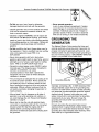
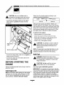
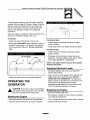
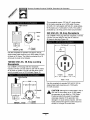
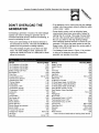
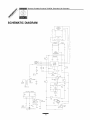
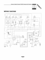
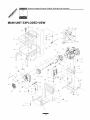
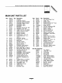
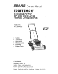
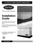
The Reliable
Ones
7500
Portable
Generator
L
Owner's Manual
A
DANGER[ This generator is designed for outdoor use only. Never use this generator inside any building
or enclosure including the generator compartment of a recreational vehicle (RV). Carbon monoxide
poisoning, fire and/or an explosion may result. No user performed modifications, including venting of
exhaust and/or cooling ventilation, will eliminate the danger. Always have at least two feet of clearance on
all sides of the generator even while operating the unit outdoors.
A
DANGER! You must isolate
circuit breaker or main switch
the power utility may result
generator due to a backfeed
the generator from the electric utility by opening the electrical system's main
if this unit is used for backup power, Failure to isolate the generator from
in injury or death to electric utility workers and damage to the
of electrical energy,
The Emission Control System for this generator is warranted for standards set by the
Environmental Protection Agency, For warranty information refer to the Engine Owner's manual.
Model No. 1019-1 (7500 Watt AC Generator) Manual No B4594 Revision 0 (11/1/1999)
Visit our Generac website: www.generac-portables.com
,_
This
Obey isallthe
safety
safetymessages
alert symbol.
that follow
It is used
this to
symbol
alert you
to avoid
to potential
possible
personal
injury or
injury
death.
hazards.
GeneracPortableProducts
7500EXLExtendedLifeGenerator
EQUIPMENT
SAFETY RULES
DESCRIPTION
This generator is an engine-driven, revolving field,
alternating current (AC) generator. It was designed to
supply electrical power for operating compatible
electrical lighting, appliance, tool and motor loads.
This manual contains information for a generator that
operates 120 and/or 240 Volts, single phase, 60Hz
devices that require up to 7500 watts (7.5 kW) of
power that pull up to 62.5 Amps at 120 Volts or
31.2 Amps at 240 Volts.
A
This generator set was designed and manufactured
for specific applications. Do Not attempt to modify the
unit or use it for any application it was not designed
for. If you have any questions about your generator's
application, ask your dealer or consult the factory.
The manufacturer could not possibly anticipate every
circumstance that might involve a hazard. For that
reason, warnings in the manual and warnings on tags
or decals affixed to the unit are not all-inclusive. If you
intend to handle, operate or service the unit by a
procedure or method not specifically recommended by
the manufacturer, first make sure that such a
procedure or method will not render this equipment
unsafe or pose a threat to you and others.
CAUTION:
Do Notcapacity
exceed the
wattage/amperage
Add generator's
up the rated
watts of all devices you are connecting to
generator receptacles at one time. This total
should not be greater than 7,500 watts for this
generator. In most cases rated watts of the
electrical device can be found on the device
Read this manual carefully and become familiar
with your generator set. Know its applications, its
limitations and any hazards involved.
nameplate. If the device nameplate gives only
volts and amps, multiply volts times amps to
obtain watts (volts x amps = watts).
The generator's revolving field is driven at about
3600 rpm by a single cylinder engine.
Every effort has been expended to make sure that the
information in this manual is both accurate and
current. However, Generac reserves the right to
change, alter or otherwise improve the product at any
time without prior notice.
A
• The generator produces a very powerful voltage that
can cause extremely dangerous electrical shock.
Avoid contact with bare wires, terminals, etc. Never
permit any unqualified person to operate or service
the generator.
DANGER: Do Not tamper with engine
governed speed. High operating speeds are
dangerous and increase risk of personal injury
or damage to equipment The generator
supplies correctly rated frequency and voltage
only when running at proper governed speed.
Incorrect frequency and/or voltage can damage
some connected electrical loads Operating at
excessively low speeds imposes a heavy load
at such reduced speeds, when adequate
engine power is not available, and may shorten
engine life
• Never handle any kind of electrical cord or device
while standing in water, while barefoot or while
hands or feet are wet.
• The National Electric Code requires the frame and
external electrically conductive parts of generator be
properly connected to an approved earth ground.
Local electrical codes may also require proper
grounding of the generator. Consult with a local
electrician for grounding requirements in your area.
• Use a ground fault circuit interrupter in any damp or
highly conductive area (such as metal decking or
steel work).
/
2
GeneracPortableProducts7500EXLExtendedLifeGenerator
• DoNot useworn,bare,frayedor otherwise
damagedelectricalcordsetswiththegenerator.
• Operategenerator
onlyonlevelsurfacesandwhere
it willnotbeexposedtoexcessivemoisture,dirt,
dustor corrosivevapors.
• Gasolineis highlyFLAMMABLE
anditsvaporsare
EXPLOSIVE.
DoNot permitsmoking,openflames,
sparksor heatin thevicinitywhilehandlinggasoline.
Avoidspillinggasolineona hotengine.Complywith
all regulations
requiringstorageandhandlingof
gasoline.
• DoNotoverfillthefueltank.Alwaysallowroomfor
fuelexpansion.
If tankis overfitled,
fuelcanoverflow
ontoa hotengineandcauseFIREor an
EXPLOSION.
• Neverstoregeneratorwithfuelin tankwhere
gasolinevaporsmightreachanopenflame,sparkor
pilotlight(asona furnace,waterheateror clothes
dryer).FIREor an EXPLOSION
mightresult.
• Generator
exhaustgasescontainDEADLY
carbon
monoxide
gas.Thisdangerous
gas,if breathedin
sufficientconcentrations,
cancause
unconsciousness
or evendeath.Operatethis
equipment
onlyintheopenairwhereadequate
ventilationis available.
• Theunitrequiresanadequateflowofcoolingairfor
itscontinuedproperoperation.Neveroperatethe
unitinsideanyroomorenclosurewherethefree
flowofcoolingairintoandoutofthe unitmightbe
obstructed.
Withoutsufficientcoolingairflow,the
unitquicklyoverheats,
damaging
the generator
or
nearbyproperty.
• Allowat least2 feetof clearance
onallsidesof
generator,
evenwhileoperatingunitoutdoors,
or
youcoulddamagethe unit.ReviewColdWeather
Operationon page9.
• Neverstartorstopthe unitwithelectricalloads
connected
to receptacles
ANDwiththe connected
devicesturnedON.Starttheengineandlet it
stabilizebeforeconnecting
electricalloads.
Disconnect
allelectricalloadsbeforeshuttingdown
thegenerator.
/
3
• Never operate generator:
in rain; in any enclosed compartment; if engine
speed changes; if connected electrical devices
overheat; if electrical output is lost; if engine or
generator sparks; if flame or smoke is observed
while unit is running; if unit vibrates excessively.
GROUNDING THE
GENERATOR
The National Electric Code requires the frame and
external electrically conductive parts of generator be
properly connected to approved earth ground. Local
electrical codes may also require proper grounding of
the unit. For that purpose, a GROUNDING WING NUT
(Figure 1) is provided on the cradle frame.
Grounding Wing Nut
Generally, connecting a No. 12 AWG (American Wire
Gauge) stranded copper wire to the grounding wing
nut and to an earth-driven copper or brass grounding
rod (electrode) provides adequate protection against
electrical shock. However, local codes may vary
widely. Consult with a local electrician for grounding
requirements in your area. Be sure to keep the
grounding wire secure while you connect to the
grounding rod.
Properly grounding the generator helps prevent
electrical shock if a ground fault condition exists in the
generator or in connected electrical devices. Proper
grounding also helps dissipate static electricity, which
often builds up in ungrounded devices.
GeneracPortableProducts
7500EXLExtendedLifeGenerator
KNOW YOUR GENERATOR
Read this owner's manual and safety rules before operating your generator.
Compare the illustrations with your generator to familiarize yourself with the locations of various controls and
adjustments. Save this manual for future reference
Circuit Breakers (AC)
Electric Start Button
12 Volt DC
Recoil Starter
Receptacle
Idle Control Switch
Choke Lever
120 Volt AC,
30 Amp Locking
Receptacle
Run/Stop Switch
Spark Arrestor Muffler
/
/
/
120 Volt AC, 20 Amp
Receptacles
240 Volt AC, 50 Amp
Receptacle
Grounding Wing Nut
12 Volt DC Receptacle i Use this receptacle with
battery charge cables to charge a 12 Volt battery.
Choke Lever
i
120/240 Volt AC, 30 Amp
Locking Receptacle
Used when starting a cold engine.
Circuit Breakers (AC) -- Each receptacle is provided
with a "push to reset" circuit breaker to protect the
generator against electrical overload.
i
120 Volt AC, 20 Amp Receptacles
May be used to
supply electrical power for the operation of 120 Volt
AC, single phase, 60 Hz electrical lighting, appliance,
tool and motor loads.
Electric
Start Switch -- Pressed to start the engine.
Grounding Wing Nut -- Use this connection to
properly ground the generator.
120 Volt AC, 30 Amp Locking Receptacle i May be
used to supply electrical power for the operation of
120 Volt AC, 30 Amp, single phase, 60 Hz electrical
lighting, appliance, tool and motor loads.
Idle Control Switch -- The idle control runs the
engine at normal (high) speeds when there is a load
present and runs the engine at idle (low) speeds when
a load is not present.
120/240 Volt AC, 30 Amp Locking Receptacle -May be used to supply electrical power for the
operation of 120 and/or 240 Volt AC, 30 Amp, single
phase, 60 Hz electrical lighting, appliance, tool and
motor loads.
Recoil Starter = Used as an alternate means of
starting the engine.
Run/Stop Switch -- Must be in "Run" position to start
engine. Set to "Stop" to stop a running engine.
240 Volt AC, 50 Amp Receptacle i May be used to
supply electrical power for the operation of 240 Volt
AC, 50 Amp, single phase, 60 Hz electrical loads.
Spark Arrestor Muffler-Exhaust muffler lowers
engine noise and is equipped with a spark arrestor
screen.
/
4
GeneracPortableProducts7500EXLExtendedLifeGenerator
Yourgeneratorrequiressomeassemblyandis ready
foruseafterit hasbeenproperlyservicedwiththe
recommended
oilandfuel.
If you have any problems with the assembly of
your generator, please call the generator
at 1-800-270-1408.
INSTALLING TRAY AND
BATTERY
You must purchase and install a 12 Volt DC battery
(Series U1-109). The battery should be serviced with
electrolyte fluid and fully charged prior to installation.
Install the battery as follows:
helpline
IMPORTANT: Any attempt to run the unit before it has
been serviced with the recommended oil will result in
• Find the battery tray and fasteners shipped loose in
the carton. The battery bracket, two 7" J-bolts, two
lock washers and two hex nuts are included.
an engine failure.
REMOVE GENERATOR
FROM CARTON
• Remove the four battery tray screws from base.
• Position the battery tray and install (Figure 2).
I
• Set the carton on a rigid flat surface with "This Side
Up" arrows pointing upward.
• Carefully open the top flaps of the shipping carton.
Review "Cold Weather Operation" on page 9.
• Cut down corners at one end of carton from top to
bottom and lay that side of carton down flat.
• Remove all packing material, carton fillers, etc.
J
• Remove the generator from the shipping carton.
J
CARTON CONTENTS
Check alt contents If any parts are missing or
damaged, call the generator helpline at
1-800-270-1408.
• Set battery onto tray and attach bracket, J-bolts, lock
washers, flat washers, and hex nuts (Figure 3).
Tighten hardware with 3/8" wrench.
• The generator
Electric start battery cables
Generator and engine owner's manuals
Locking 20 Amp and 30 Amp plugs
Battery charge cables
Battery tray mounting bracket/hardware
Spare spark plug and air filter element
Spark plug wrench
/
5
GeneracPortableProducts
7500EXLExtendedLifeGenerator
,_.
Select the oil's viscosity grade according to your
expected operating temperature:
CAUTION: to Be
the mount
black cable
is the
connected
thesure
engine
and not
frame. You could damage the ground wire.
!
• Connect the red battery cable from the engine
starter switch to positive (+) battery terminal
(Figure 4)
I
colder 5W-30
_
32°F
-_,_warmer
10W-30
Although multi-viscosity oils (5W30, 10W30, etc.)
improve starting in cold weather, these multi-viscosity
oils will result in increased oil consumption when used
above 32°E Check your engine oil level frequently to
avoid possible damage from running low on oil. See
the engine owner's manual for further information.
To add oil to the engine:
• Place generator on a level surface.
• Clean area around oil fill and remove oil cap.
• Slowly add oil through the oil fill opening until it
reaches the top. DO NOT OVERFILL.
• Install oil cap, hand tighten securely.
,_
CAUTION:
attempt
crank orserviced
start the
engine
beforeAny
it has
beentoproperly
with the recommended oil will result in an
engine failure.
NOTE: The generator's revolving field rides on a prelubricated and sealed ball bearing that requires no
additional lubrication for the life of the bearing.
Add Fuel
• Connect the black battery cable to the negative (-)
battery terminal (Figure 4).
• Connect the other end of the black cable to the
engine, not the frame.
BEFORE STARTING THE
ENGINE
Perform the following tasks before trying to start the
generator engine:
,_
DANGER:
NEVER
fuel engine
tank indoors.
NEVER fill fuel
tank fill
when
is running or
hot. Do Not light a cigarette or smoke when
filling the fuel tank
,_.
CAUTION:
Notfor
overfill
the fuel tank
Always
allow Do
room
fuel expansion.
Use only regular UNLEADED
gasoline.
IMPORTANT: It is important to prevent gum deposits
from forming in essential fuel system parts such as the
carburetor, fuel filter, fuel hose or tank during storage.
Also, experience indicates that alcohol-blended fuels
(called gasohol, ethanol or methanol) can attract
moisture, which leads to separation and formation of
acids during storage. Acidic gas can damage the fuel
system of an engine while in storage.
Add Engine Oil
NOTE: In the future, When adding oil to the engine
crankcase use only high quality detergent oil rated
with API service classification SF and SG. Use no
special additives DO NOT USE SAE 10W-40.
/
6
GeneracPortableProducts7500EXLExtendedLifeGenerator
Toavoidengineproblems,thefuelsystemshouldbe
emptiedbeforestorageof30daysorlonger.Drainthe
gastank,startthe engineandlet it rununtilthefuel
linesandcarburetor
areempty.Usefreshfuelnext
season.See"Storage"onpage12foradditional
information.
Neveruseengineor carburetorcleanerproductsinthe
fueltankor permanent
damagemayoccur.
To add fuel:
For Electric
• Clean area around fuel fitl cap, remove cap.
Start:
• Prepare engine for starting according to engine
owner's manual
• Slowly add "UNLEADED" regular gasoline, slowly, to
fuel tank. Leave about a 1/2" space in the fuel tank
for fuel expansion (Figure 5). Do Not overfill fuel
tank.
• Press starter switch until engine cranks and starts.
For Manual Start:
• Prepare engine for starting according to engine
owner's manual.
• Pull slowly on recoil handle until you feel some
resistance. Then pull rapidly to start engine. Return
recoil slowly, Do Not let it "snap back".
.1/2" Air Space
Refer to the engine owner's manual for complete
starting instructions.
Applying
Electrical
Loads
• Let engine stabilize and warm up for about five
minutes after starting.
• Plug in and turn on the desired 120 or 240 Volt AC,
single phase, 60 Hz electrical loads. DO NOT
OVERLOAD THE GENERATOR. The total rated
• Install fuel cap and wipe up any spilled gasoline.
OPERATING THE
GENERATOR
,_.
watts (or amps) of all loads to be connected at one
time should not be greater than the rated
wattage/amperage capacity of the generator. See
"Don't Overload the Generator" on page 11.
Stopping
with electricalNever
CAUTION!
loads start,
connected
or stop,to the
the generator
unit AND
with the connected devices turned ON.
the Engine
• Disconnect all electrical loads
Starting the Engine
• Run engine at no-load for a few minutes to stabilize
unit's internal temperatures.
• Disconnect all electrical loads from the generator
• Turn off engine according to engine owner's manual.
• Open the fuel shut-off valve, as shown in Figure 6.
• Close the fuel shut-off valve
i
7
GeneracPortableProducts
7500EXLExtendedLifeGenerator
Operating
Automatic
To recharge
Idle Control
This switch is designed to greatly improve fuel
economy. When this switch is turned ON, the engine
will only run at its normal high governed engine speed
when an electrical load is connected. When an
• If the battery is equipped with vent caps, make sure
they are installed and are tight.
electrical load is removed, the engine wilt run at a
reduced speed. With the switch OFF, the engine will
run at the normal high engine speed. Always have
the switch OFF when starting and stopping the
engine.
• If necessary, clean battery terminals.
• Connect battery charge cable connector plug to
panel receptacle identified by the words
"12-VOLTS D.C.".
• Connect battery charge cable clamp with red handle
to the positive (+) battery terminal (Figure 7).
Battery Safety
A
,_ll
DANGER: Storage batteries give off explosive
hydrogen gas while recharging. An explosive
mixture will remain around the battery for a
long time after it has been charged. The
slightest spark can ignite the hydrogen and
cause an explosion, which can shatter the
battery and cause blindness or other injury.
12 VOLT D.C.
RECEPTACLE
Red
\
Black
DANGER:
smoking,of open
flame,
sparksDoorNot
any permit
other source
heat
around a battery. Wear protective goggles,
rubber apron and rubber gloves when working
around a battery. Battery electrolyte fluid is an
extremely caustic sulfuric acid solution that can
cause severe bums. If spill occurs flush area
with clear water immediately.
Charging
12 Volt batteries, proceed as follows:
• Check fluid level in all battery cells If necessary,
add ONLY distilled water to cover separators in
battery cells. Do Not use tap water.
+
POS
NEG
• Connect battery charge cable clamp with black
handle to the negative (-) battery terminal,
(Figure 7).
a Battery
• Start engine. Let the engine run while battery
recharges.
Your generator has the capability of recharging a
discharged 12 Volt automotive or utility style storage
battery. Do Not use the unit to charge any 6 Volt
batteries Do Not use the unit to crank an engine
having a discharged battery
• When battery has charged, shut down engine
NOTE: Use an automotive hydrometer to test battery
state of charge and condition. Follow the hydrometer
manufacturer's instructions carefully. Generally, a
battery is considered to be at 100% state of charge
when specific gravity of its fluid (as measured by
hydrometer) is 1.260 or higher.
/
8
GeneracPortableProducts7500EXLExtendedLifeGenerator
COLD WEATHER
OPERATION
• Ensure a minimum of two feet clearance between
open side of box and nearest object
Under certain weather conditions (temperatures below
40°F [4°C] and a high dew point), your Generac
generator may experience icing of the carburetor
and/or the crankcase breather system.
• Enclosure should hold enough heat created by the
generator to prevent problems.
• Face exposed end away from wind and elements.
,_.
In an emergency, use the original shipping box as a
temporary shelter:
• Cut off all flaps.
CORD SETS/RECEPTACLES
• Cut out one of the long sides of the box to expose
exhaust side of unit. Ensure a minimum of two feet
clearance between open side of box and nearest
object.
This generator is equipped with the following
receptacles:
• Cut appropriate slots to access receptacles and
clear handles.
120 Volt AC, 20 Amp Receptacle
• Start unit, then place box over it.
IMPORTANT!: Remove shelter when temperature
above 40°F [4°C].
CAUTION:
NEVERany
runmore
unit than
indoors;
Do Not
enclose
generator
shown.
Remove shelter when temperatures are above
40°F [4°C].
This outlet is protected against overload by a 20 Amp
)ush-to-reset circuit breaker.
is
For a more permanent shelter, build a structure that
will enclose three sides and the top of the generator:
• Make sure entire muffler-side of generator is
exposed. Note that your generator may appear
different from that shown in Figure 8.
Use each socket to operate 120 Volt AC, single phase
60 Hz electrical loads requiring up to 2400 watts
(2.4 kW) at 20 Amps (Figure 9). Use cord sets that are
rated for 125 Volt loads at 20 Amps (or greater).
120 Volt AC, 30 Amp Locking
Receptacle
Use a NEMA L5-30 plug with this receptacle Connect
a 3-wire cord set rated for 125 Volt AC loads at
30 Amps to the plug (Figure 10).
/
9
Generac Portable Products 7500EXL Extended Life Generator
This receptacle powers 120 Volt AC, single phase,
60 Hz loads requiring up to 3,600 watts of power
(3.6 kW). Or it will operate 240 Volt AC, single phase,
60 Hz loads up to 7,200 watts 7.2 kW). The outlet is
protected by a 30 Amp push-to-reset circuit breaker.
3-Wire Cord Set
Neutral
240 Volt AC, 50 Amp Receptacle
Use a NEMA 14-50 plug with this receptacle Connect
a 4-wire cord set rated for 240 Volt AC loads at
50 Amps to the plug (Figure 12).
120V
Hot
_=========
240 Volts A¢ ===========_
NEMA L5-30
r7_7 Ground
(Green)
Use this receptacle to operate 120 Volt AC, 60 Hz,
single phase loads requiring up to 3600 watts (3.6 kW)
of power at 30 Amps. The outlet is protected by a 30
Amp push-to-reset circuit breaker.
120/240 Volt AC, 30 Amp Locking
Receptacle
Use a NEMA L14-30 plug with this receptacle.
Connect a 4=wire cord set rated for 250 Volt AC loads
at 30 Amps or greater. You can use the same 4-wire
cord if you plan to run a 120 Volt load (Figure 11)
4-Wire Cord Set
NEMA ]4-50
Use this receptacle to operate 240 Volt AC, 60 Hz,
single phase loads requiring up to 7,500 watts
(7.5 kW) of power.
A
Y (Hot)
X (Hot)
Ground
NEMA L14-30
(Green)
/
10
CAUTION! Although this outlet states it has a
250 Volt 50 Amp rating (up to 12,500 watts),
the generator is only rated for 7,500 Watts.
Powering loads that exceed the wattage/
amperage capacity of the generator can
damage it or cause serious injuries. 240 Volt
loads powered through this outlet should not
exceed 31.2 Amps of current draw.
GeneracPortableProducts7500EXLExtendedLifeGenerator
DON'T OVERLOAD
GENERATOR
THE
• If the appliance, tool or motor does not give wattage,
multiply volts times ampere rating to determine watts
(volts x amps = watts).
• Some electric motors, such as induction types,
require about three times more watts of power for
starting than for running. This surge of power lasts
for only a few seconds when starting such motors.
Be sure you allow for this high starting wattage
when selecting electrical devices to connect to your
generator, First figure the watts needed to start the
largest motor. Add to that figure the running watts of
all other connected loads.
Overloading a generator in excess of its rated wattage
capacity can result in damage to generator and to
connected electrical devices. Observe the following, to
prevent overloading the unit:
• Add up the total wattage of all electrical devices to
be connected at one time. This total should NOT be
greater than the generator's wattage capacity,
• The rated wattage of lights can be taken from light
bulbs The rated wattage of tools, appliances and
motors can usually be found on a data plate or decal
affixed to the device.
Device ..............
Running
*Air Conditioner (12,000 Btu) ....................
*Air Conditioner (24,000 Btu) ....................
*Air Conditioner (40,000 Btu) ....................
Battery Charger (20 Amp) ........................
Belt Sander (3") ...............................
Chain Saw ...................................
Circular Saw (6-1/2") .....................
*Clothes Dryer (Electric) ........................
*Clothes Dryer (Gas) ............................
*Clothes Washer ..............................
Coffee Maker .................................
Watts
1700
3800
6000
500
1000
1200
Device ..............
Hedge Trimmer ................................
Impact Wrench ................................
Iron ........................................
2000
1800
1400
700
700
650
Disc Sander (9") ..............................
Edge Trimmer .................................
Electric Blanket ................................
Electric Nail Gun ..............................
1200
500
400
1200
Electric Range (per element) .....................
Electric Skillet ................................
1500
1250
Running
*Jet Pump ....................................
Lawn Mower .................................
Light Bulb ....................................
Microwave Oven .........................
*Milk Cooler ..................................
Oil Burner on Furnace ...........................
Oil Fired Space Heater (140,000 Btu) ...............
Oil Fired Space H eater (85,000 Btu) ...............
Oil Fired Space Heater (30,000 Btu) ................
*Paint Sprayer, Airless (1/3 HP) ...................
Paint Sprayer, Airless (handheld) ..................
Radio ...................................
800 to 1000
5750
700
1150
1750
*Compressor (1 HP) ...........................
*Compressor (3/4 HP) ..........................
*Compressor (1/2 HP) ..........................
Cuding Iron ...................................
*Freezer ......................................
*Dehumidifier ..................................
*Furnace Fan (3/5 HP) ..........................
*Garage Door Opener .....................
Hair Dryer ...................................
Hand Drill ..............................
• The Wattage Guide shown in Figure 13 is provided
to help you to determine how many items the
generator can operate at one time.
*Refrigerator ..................................
Slow Cooker ..................................
*Submersible Pump (1-1/2 HP) ...................
*Submersible Pump (1 HP) ......................
*Submersible Pump (1/2 HP) ....................
*Sump Pump ...........................
*Table Saw (10") ........................
Television ...............................
Toaster ...............................
Weed Trimmer .................................
875
500 to 750
1200
250 to 1100
Watts
450
500
1200
800
1200
100
700 to 1000
1100
300
400
225
150
600
150
50 to 200
700
200
2800
2000
1500
800 to 1050
1750 to 2000
200 to 500
1000 to 1650
500
* Allow 3 times the listed watts for starting these devices.
/
11
Generac Portable Products 7500EXL Extended Life Generator
GENERAL MAINTENANCE
RECOMMENDATIONS
STORAGE
The generator should be started at least once every
seven days and allowed to run at least 30 minutes If
this cannot be done and you must store the unit for
more than 30 days, use the following guidelines to
prepare it for storage.
The Owner/Operator is responsible for making sure
that all periodic maintenance tasks are completed on a
timely basis; that all discrepancies are corrected; and
that the unit is kept clean and properly stored. Never
operate a damaged or defective generator.
• Clean the generator as outlined in "To Clean the
Generator."
• Check that cooling air slots and openings on
generator are open and unobstructed.
Engine Maintenance
See engine manual for instructions
Generator
• Disconnect the negative battery cable from the
battery.
Maintenance
Generator maintenance consists of keeping the unit
clean and dry Operate and store the unit in a clean
dry environment where it will not be exposed to
excessive dust, dirt, moisture or any corrosive vapors.
Cooling air slots in the generator must not become
clogged with any foreign material.
,_ll
DANGER:
Storage
covers
canover
be flammable.
Do
Not place
a storage
cover
a hot
generator. Let the unit cool for a sufficient time
before placing the cover on the unit.
Engine Storage
Check the cleanliness of the generator frequently and
clean when dust, dirt, oil, moisture or other foreign
substances are visible on its exterior surface.
See engine owner's manual for instructions on how to
properly store the engine.
NOTE: Do Not use a garden hose to clean generator.
Water can enter engine fuel system and cause
problems. In addition, if water enters generator
through cooling air slots, some of the water will be
retained in voids and cracks of the rotor and stator
winding insulation. Water and dirt buildup on the
generator internal windings will eventually decrease
the insulation resistance of these windings.
Other Storage Tips
• Do Not store gasoline from one season to the next.
• Replace your gasoline can if it starts to rust. Rust
and/or dirt in a gasoline can cause problems when
you use that fuel with this unit.
• Store unit in clean and dry area.
SPECIFICATIONS
To Clean the Generator
Rated Maximum Continuous
• Use a damp cloth to wipe exterior surfaces clean.
• A soft bristle brush may be used to loosen caked-on
dirt or oil.
AC Power Output ...................................
7500 watts (7.5 kW)
Rated Voltage .........................................
120/240 Volts
Rated Maximum AC Current
• A vacuum cleaner may be used to pick up loose dirt
and debris.
• Low pressure air (not to exceed 25 psi) may be
used to blow away dirt. Inspect cooling air slots and
opening on generator.
SERVICE/ADJUSTMENTS
at 120 Volts .........................................
62.5 Amps
at 240 Volts .........................................
31.2 Amps
Phase .....................................................
1
Rated AC Frequency ..............................
60 Hertz
Number of Rotor Poles ........................... 2
Driven Speed of Rotor ............................ 3600 rpm
Refer to engine owner's manual for information
i
12
GeneracPortableProducts7500EXLExtendedLifeGenerator
TROUBLESHOOTING
Cause
Problem
Engine is running, but
no AC output is
available.
Engine runs good but
bogs down when
loads are connected.
Engine will not start;
or starts and runs
rough,
1.
2.
3.
Circuit breaker is open.
Poor connection or defective cord set
Connected device is bad
4.
1.
2.
Fault in generator.
Short circuit in a connected load.
Generator is overloaded.
3.
4.
1.
2.
3.
4.
Engine speed is too slow.
Shorted generator circuit.
Run/Stop switch set to"Stop".
Dirty air cleaner.
Out of gasoline.
Stale gasoline.
5.
Spark plug wire not connected to
spark plug.
Bad spark plug.
Water in gasoline.
Overchoking.
6.
7.
8.
9.
10.
11.
12.
Engine shuts down
during operation.
Engine lacks power.
Engine "hunts"
falters.
1.
2.
Low oil level.
Excessively rich fuel mixture.
Intake valve stuck open or closed.
Engine has lost compression.
Out of gasoline.
Low oil level.
3.
1.
Fault in engine.
Load is too high.
2.
3.
1.
Dirty air filter.
Engine needs to be serviced.
Choke is opened too soon.
2.
Carburetor is running too rich or too
lean.
or
/
13
Solution
1. Reset circuit breaker.
2. Check and repair.
3. Connect another device that is in
good condition.
4. Contact Generac service facility.
1. Disconnect shorted electrical load.
2. See "Don't Overload the GeneratoY'
on page 11.
3. Contact Generac service facility.
4. Contact Generac service facility.
1. Set switch to "Run".
2. Clean or replace air cleaner.
3. Fill fuel tank.
4. Drain gas tank and fill with fresh
fuel.
5. Connect wire to spark plug.
6.
7.
8.
Replace spark plug.
Drain gas tank; fill with fresh fuel.
Put choke lever at "No Choke"
position.
9. Fill crankcase to proper level,
10. Contact Generac service facility,
11. Contact Generac service facility,
12. Contact Generac service facility,
1. Fill fuel tank.
2. Fill crankcase to proper level.
3. Contact Generac service facility,
1. See"Don't Overload the GeneratoP
on page 11.
2. Replace air filter.
3. Contact Generac service facility.
1. Move choke to halfway position till
engine runs smoothly.
2. Contact Generac service facility,
ID]_LF_i_]_
SCHEMATIC
GeneracPortableProducts
7500EXLExtendedLifeGenerator
DIAGRAM
G
35_
L
155
156
2@
44
SYSTEH
CONTROL
18
s
BOARD
I
L0P
IDLE
I
14
0 B
BLU/_HT
2_
Generac Portable Products 7500EXL Extended Life Generator
ID_'!
_
WIRING DIAGRAM
10A
C_B_
AUTD RESET
J
•
120V/20A
120/240v
IDLE
CONTROL
SWITCH
GRN/YEL
/x
TRAN_FDRHER
IDLE
¢DNTRDL
¢
RUN
_N
NUT ON
ENGINE
BLOCK
I
15
Generac Portable Products 7500EXL Extended Life Generator
I
_j/-
I
MAIN UNIT EXPLODED VIEW
62
66
67
/
DETAIL OF
ELECTRIC START
SWITCH
51
68
/
65
TO STARTER
38
10
\\
<
1/
65\
51
\
16\
58
17
57
26
33
13--
_9
\
37
55
57
\65
\
\,
21
/
16
Generac Portable Products 7500EXL Extended Life Generator
Ill
I
m
MAIN UNIT PARTS LIST
Item
1
2
3
4
5
6
7
8
9
10
11
12
13
14
15
Part #
A92432
A92531
A92731
92247
B1342G
B1897G
65791
67451
22129
86307
47481
92609
82857
40976
66476
Qty.
1
1
1
1
1
1
1
1
12
4
1
2
4
2
2
16
17
18
19
20
21
25
26
27
28
29
30
31
32
33
34
35
92532
22142
91153
90239
81917
B4986
66825C
74908
66449L
65795
66849C
67022
84132
66386
66849
B78388
22769
1
2
1
1
1
1
1
4
4
2
1
1
1
1
2
1
1
36
37
38
39
40
41
42
86494
B2153
77395
83465
57058
80270
78299
1
9
4
4
4
1
1
Description
CRADLE
SUPPORT, Engine
SUPPORT, Engine & Muffler
HOUSING, Engine Adapter
ASSEMBLY, Rotor
ASSEMBLY, Stator
BEARING
WASHER, Special Flat - M8
WASHER, Lock- M8
HHMS, 5/16-24 x 3/4 SEMS
HHCS, 5/16-24 x 10.625
MOUNT, Vibration
MOUNT, Vibration
SCREW, M8 - 1.25 x 20
CAPSCREW, M6 - 1.0 x
12mm
BRACKET, Muffler
SCREW, 5/16 - 18 x 3/4
MUFFLER
GASKET, Muffler
PIN, Roll 4mm x 10
DECAL, Ground
CARRIER, Rear Bearing
TAPTITE, M5-0.8 x 10
BOLT, Stator M6-1 x 190mm
RECTIFIER, Battery Charge
TAPTITE, M5-0.8 x 30
GROMMET, Rubber
ASSEMBLY, Power Regulator
ASSEMBLY, Brush Holder
TAPTITE, M5-0.8 x 16
COVER, Bearing Carrier
WASHER, Shakeproof Int.
#10
SCREW, M6-1.0 x 16 Wing
HHCS, - #10 Self Driller
NUT, Flange Lock - M6
GROMMET, Tank
HHMS, M6-1.0 x 55
VALVE, Tank
BUSHING, Tank
Item
43
44
45
46
47
48
49
50
51
52
55
57
58
59
60
62
63
64
65
66
67
68
69
70
Part #
Qty.
B4363
1
B1998
1
B92039
1
92665
1
85000
1
14353621 1
26850
2
57593
1
92982
1
B4569
2
25244
12
B4569
1
B4366
1
NSP
1
22531
2
93826
1
B96068
1
56893
5
77282
1
22287
2
22097
2
22127
2
78289
1
22473
4
Parts Not Illustrated
A96923
1
96924
2
22129
2
45771
2
22145
2
15453621 1
15553621 1
37806
1
43438
1
65787
1
A96925
1
B4594
1
72347
1
73111
1
84882
1
/
17
Description
CAP, with Gauge, Fuel
TANK, Fuel
SHIELD, Heat
INSULATION, #2-1/4" Thick
CLIP, Insulation
WIRE, Ground
LW, EXT, Shakeproof M6
MOUNT, Cable Tie
DECAL, Danger
DECAL, Heat Shield
NUT, 5/16-18 Hex
DECAL, Control Panel
ASSEMBLY, Control Box
ENGINE
HHCS, 5/16-18 x 1-3/4"
DECAL, Start Instructions
SHIELD, Heat
CRIMPTITE, 10-24 x 1/2
SWITCH, Starter
SCREW, 1/4 - 20 x 3/4
LOCKWASHER, M6
NUT, 1/4 - 20 Hex
BRACKET, Starter Switch
WASHER, M6 Flat
Tray, Battery
J-Bolt, M8 - 1.25
Lockwasher
Hex nut M8
Flat Washer
Cable, Positive Battery
Cable, Negative Battery
120V 30 A plug
120/240V 30 A plug
Cable, Battery Charge
Bracket, Tie Down
Manual, owner's
Spark Plug
Air Cleaner Element
Spark Plug Wrench
I=&'_J-#J"d |
Generac Portable Products 7500EXL Extended Life Generator
I
? j/_
CONTROL
I
PANEL EXPLODED VIEW AND PARTS LIST
19
2C
21
25
28
27
26
lO
lO
12
17 18
13
J24
7
18
17
>9
12
_
L$.\
2
\
3
Item
1
2
3
4
5
6
7
8
9
10
11
12
13
14
Pa_ #
BB4461
23897
49226
91526
82538
82881
B4262
90418
75207N
75207A
75207
23365
68868
43437
Qty.
1
4
4
4
1
6
1
1
2
2
2
10
1
1
Description
PANEL, Control
WASHER, #10 M5 Flat
WASHER, M5 Lock
SCREW, M5-0.8 x 12 mm
SWITCH, Idle Control
WASHER, 7/16" Int. Lock
OUTLET, 50A, 240V
OUTLET, 10A, 12VDC
CIRCUIT BREAKER, 35 Amp
CIRCUIT BREAKER, 30 Amp
CIRCUIT BREAKER, 20 Amp
WASHER, #8 Shakeproof
OUTLET, 30A, 120V Locking
OUTLET, 30A, 120V/240V
Locking
I
18
Item
15
16
17
18
19
20
21
22
Pa_ #
68759
43180
22264
51715
64526
83970
64525
87962
Qty.
1
10
10
10
8
1
4
1
23
24
25
26
27
28
84335
84134
B92069
84028
43181
43182
1
1
1
1
4
4
Description
OUTLET, 20A,120V
WASHER, M4 Flat
WASHER, #8 M4 Lock
NUT, M4 - 0.7 Hex
SCREW, #6-32 x 3/8"
BOARD, System Control
3/4" Hex Standoff
CIRCUIT BREAKER, 10A
(automatic), 12V
ASSEMBLY, Wire Harness
GROMMET, Rubber
BOX, Control Panel
TRANSFORMER, Idle Control
SCREW, M3 - 0.5 x 10 mm
WASHER, M3 Lock
GeneracPortableProducts7500EXLExtendedLifeGenerator
NOTES
/
19
LIMITED WARRANTY
FOR "GN"
ENGINE
DRIVEN
PORTABLE
GENERATORS
GENERAC PORTABLE PRODUCTS (hereafter referred to as the COMPANY) warrants to the original purchaser
that the alternator and control panel for its portable generator will be free from defects in materials or
workmanship for the items and period set forth below from the date of original purchase. This warranty is not
transferable and applies only to portable generators driven by a GN-Series engine. This warranty does not apply
to starting battery, rechargeable flashlight or battery charger.
Consumer*
Alternator
Engine
Commercial*
2 years (2nd year parts only)
1 year
Warranted solely by the engine manufacturer
With the exception of European Community Countries, all units bound for export shall be warranted for
One (1) Year in Consumer applications, and 90 days in Commercial applications as defined below.
*NOTE: For the purpose of this warranty "consumer use" means personal residential household use by
original purchaser. This warranty does not apply to units used for Prime Power in place of utility.
"Commercial
Use" means all other uses, including rental, construction, commercial and income
producing purposes. Once a generator has experienced commercial use, it shall thereafter be considered
a commercial use generator for the purposes of this warranty.
During said warranty period, the COMPANY wilt, at is option, repair or replace any part which, upon examination
by the COMPANY, is found to be defective under normal use and service**. Starting batteries are not warranted
by the COMPANY. All transportation costs under warranty, including return to the factory if necessary, are to be
borne by the purchaser and prepaid by the purchaser. This warranty does not cover normal maintenance and
service and does not apply to a generator set, alternator, or parts which have been subjected to improper or
unauthorized installation or alteration, misuse, negligence, accident, overloading, overspeeding, improper
maintenance, repair or storage so as, in the COMPANY's judgement, to adversely affect its performance and
reliability.
**NORMAL WEAR: As with all mechanical devices, the generator need periodic parts service and
replacement to perform well. This warranty will not cover repair when normal use has exhausted the life
of a part or generator.
THERE IS NO OTHER EXPRESS WARRANTY. THE COMPANY HEREBY DISCLAIMS ANY AND
ALL IMPLIED WARRANTIES, INCLUDING BUT NOT LIMITED TO THOSE OF MERCHANTABILITY
AND FITNESS FOR A PARTICULAR PURPOSE TO THE EXTENT PERMITTED BY LAW. THE
DURATION OF ANY IMPLIED WARRANTIES WHICH CANNOT BE DISCLAIMED IS LIMITED TO
THE TIME PERIOD AS SPECIFIED IN THE EXPRESS WARRANTY. LIABILITY FOR
CONSEQUENTIAL, INCIDENTAL OR SPECIAL DAMAGES UNDER ANY AND ALL WARRANTIES
IS EXCLUDED. THE COMPANY ALSO DISCLAIMS ANY RESPONSIBILITY FOR INCIDENTAL OR
CONSEQUENTIAL DAMAGES, SUCH AS THE LOSS OF TIME OR THE USE OF THE POWER
EQUIPMENT, OR ANY COMMERCIAL LOSS DUE TO THE FAILURE OF THE EQUIPMENT: AND
ANY IMPLIED WARRANTIES ARE LIMITED TO THE DURATION OF THIS WRITTEN
WARRANTY.
Some states do not allow limitations on how long an implied warranty lasts, or the exclusion or limitation of
incidental or consequential damages, so the above limitations or exclusions may not apply to you. This warranty
gives you specific legal rights and you may also have other rights, which vary from state to state.
For service, see your nearest COMPANY authorized warranty service facility or call 1-877-544-0982. Warranty
service can be performed only by a COMPANY authorized service facility. This warranty will not apply to service
at any other facility. At the time of requesting warranty service, evidence of original purchase date must be
presented.
GENERAC
PORTABLE
Jefferson,
Wisconsin
PRODUCTS
53549