1
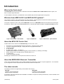
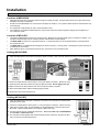
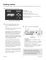
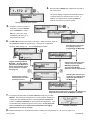
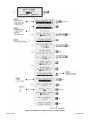
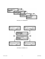
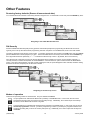
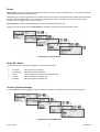
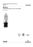
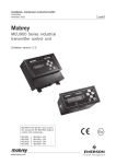
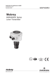
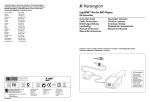
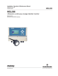
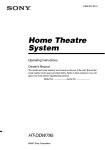
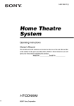
Quick-start Manual
IP2042/QS, Rev. AA
January 2006
MSP-ULOG1/MSP-ULOG2
Quick-start: For MSP-ULOG1/MSP-ULOG2
www.mobrey.com
Introduction
What is this Quick-start?
This Quick-Start is for anyone who has to install and commission the MSP-ULOG1 or MSP-ULOG2 ultrasonic system, and
does not need in-depth information.
For full installation instructions, you must refer to the installation (IM) manuals supplied with the equipment.
What are these MSP-ULOG1 and MSP-ULOG2 systems?
They are level, contents, or flow measurement and control systems. Typical applications include wet well level (and pump)
control, tank contents measurement, and open channel flow measurement.
The system comprises a mains or DC powered MCULOG control unit, an MSP900SH ultrasonic transmitter with a mounting kit,
and manuals. MSP-ULOG1 has the wall-mounted version of the MCULOG; MSP-ULOG2 has the panel-mounted MCULOG.
Figure 1: MCULOGW – wall-mounted
Figure 2: MSP900SH
Figure 3: MCULOGP – panel-mounted
About the MCULOG Control Unit
The MCULOG unit is a member of the MCU900 family of control units. It has:
•
•
•
•
•
•
•
•
•
Full support for a single MSP900SH ultrasonic transmitter – measuring level by default
a 4-line LCD display with back light – displays both text and graphical information
a 6 button keypad
an LED indicator
an intuitive menu system – for setting up
2 digital inputs (voltage-free contacts) for triggering various activities (e.g. displaying a message)
5 relay outputs (e.g. for controlling pumps, indicating alarms, etc.)
a 4-20mA output
a 4,800 event logging capability.
All setting up is achieved from the front panel of the MCULOG control unit.
About the MSP900SH Ultrasonic Transmitter
This is a loop-powered transmitter, factory sealed and fitted with cable ready to install on aqueous applications. The transmitter
is pre-configured to measure liquid level and communicates values to the MCULOG.
The other manuals
The following manuals are supplied along with this Quick-start manual:
MSP900SH:
Installation manual (IP2040/IM)
Safety instructions (IP2040/SI)
MCULOG:
Installation manual (IP2030/IM)
Safety instructions (IP2030/SI)
Full operation manuals IP2030/OM and IP2040/OM are available on request from Mobrey Measurement, and are available on the
web at www.mobrey.com
(IP2042/QS)
2
January 2006
Installation
IMPORTANT - For hazardous area installations, you must refer to the installation (IM) manuals supplied with the system.
Location of MSP900SH
•
Install the transmitter above the liquid surface using the bracket provided. Important instructions for an open channel flow
installation are given in IP2040/IM.
•
Do not mount the MSP900SH on a structure that is subject to vibration, or in a position where impact or thermal stress may
cause damage.
•
The equipment is not intended for use in areas exposed to dust.
•
The equipment must not be installed directly in any process where the enclosure might be charged by the rapid flow of
non-conductive media.
Location of MCULOG
•
The MCULOG must not be located in a hazardous area. Do not mount the MCULOG where it is subject to vibration, or in
a position where damage may be caused by impact, thermal stress or liquid ingress.
•
The MCULOGW is housed in a tough IP65 enclosure. If mounted outside, it is recommended that the unit be protected
from direct heavy rain.
•
The MCULOGP is a standard DIN size designed for direct mounting in a control panel. It is designed for panel mounting in
a weatherproof environment.
•
Allow sufficient space around the MCULOG for easy connection to the download socket.
Cabling (MCULOGW)
1. Cable the MSP900SH to the MCULOG using the gland provided. (Undo 2 screws and lift cover away to reveal terminals).
2. Check the voltage selector switch (230V or 115V) and adjust if necessary. (Mains unit only).
3. Cable the power lead to the MCULOG using the gland provided. Do not apply power yet.
4. Make connections to relay terminals and current output terminals, if required.
5. Seal unused cable entries with the blanking plugs provided.
6. Replace and secure the terminal cover.
Cabling (MCULOGP)
1. Cable the MSP900SH transmitter to terminals 1, 2 and 3 on the rear panel of the MCULOG.
(See figure inset, right)
2. Check the voltage selector switch (230V or 115V) and adjust if necessary. (Mains unit only).
3. Cable the AC power supply to terminals 28 (Live) and 29 (Neutral) on the rear panel of the
MCULOG. Note that mains Earth is not required. (Mains unit only).
4. Connect terminal 30 to an Intrinsically Safe Earth. This is essential only if the MSP900SH
is in located in a hazardous area.
5. The download socket supplied with the MCULOG should be mounted on the panel to allow
easy connection of the download device.
January 2006
3
(IP2042/QS)
Getting started
After completing the installation of both MCULOG control unit and the MSP900SH transmitter, the next stage is to switch on.
1. Familiarise yourself with the front panel fascia.
Key to figure:
c 4-line LCD with backlight.
d Keypad with 6 function keys.
e Status LED – flashes once per second if okay.
Note: The model type is shown on the LCD display in the
bottom, right-hand corner.
Front Panel Fascia of MCULOGW
2. Switch on the MCULOG by applying the power.
Wait for the primary display (inset, right) to
3. Familiarise yourself with the primary display.
appear.
During this time, the MCULOG will read parameters
from the MSP900SH transmitter.
If being used for the first time, it will prompt for the
Bottom Reference of the MSP900SH transmitter
and then automatically set-up the 4-20mA output
span over this range. If you do not want to
commission the system now, simply switch off
the power – the same prompt will then re-appear
Primary Display
when switching on the next time.
Key to figure:
If you are commissioning the system, edit the
Bottom Reference with the arrow-keys and then
1. Off-line/on-line status. (Locked padlock = on-line)
(See page 10)
press the yellow key to confirm the value. The
2. Digital input status. (o = de-energised, = energised)
Bottom Reference can be changed at a later stage
3. Measured variable (P.V.) and units of measurement.
but it is better to get it correct now. Should you
4. Bar graph of 4-20mA output of MCULOG.
press the red (ESC) key, the MCULOG will continue
5. Relay (RL) status. (o = de-energised, = energised)
and the Bottom Reference prompt will re-appear
6. Digital communication in progress. (Absent if idle)
when switching on the next time.
7. Shows specific model type.
Once the start-up is completed, the primary display
should appear, showing the measured depth of the
Note: If a “Find Instrument” screen appears and
liquid in the tank. The value on the primary display
remains, power off. Check the cabling and then try
is the P.V. (Primary Variable).
again. If the problem persists, follow the on-screen
prompts until the primary display appears.
(IP2042/QS)
4
January 2006
4.
Press the yellow (ENTER) key to display the top-level of
the menu system.
The primary display re-appears automatically if there is
no keypad activity for several minutes, if on-line. In
addition, it re-appears when pressing the ESC key
whilst at the top level of the menu system.
How to display the menu system
5.
Navigation of the menu system is
achieved by using the ARROW
keys, the ENTER key, and the
ESC key. (See figure, right).
The ESC key will return you to
the previous menu level.
6.
The Main Menu sits above a series of sub-menus. Within the menus, there are
also parameter screens for programming – setting up for an application,
Selecting this will bring up
the “Set-up” menu for
programming the MCULOG.
adjusting default settings, etc. – and for displaying information.
Toggles operating mode for
MCULOG. An open padlock
indicates that the MCULOG is
off-line and parameter values
can be entered or changed.
(See page 10)
Selecting this will bring up the
“Set-up” menu for optional
MSP900 programming.
The transmitter Bottom
Reference can be changed here.
Selecting this will allow you
to monitor live readings and
diagnostic information for
the MCULOG.
Direct access menu for
advanced users to select
parameter screens.
Selecting this will allow you to monitor live readings and
diagnostic information from the MSP900 transmitter.
7. Programming the MCULOG unit is best achieved through easy-to-follow
Wizards. They are simply a sequence of on-screen prompts, allowing you
to easily set-up an individual function or a large application without fuss.
There is a collection of Wizards for most functions and applications. They
are all selected and started through the menu system. On the pages that
follow, examples for open channel flow measurement and logging
Example of a Wizard
applications show how to use them.
8. Additional features, such as password protection, resetting to factory defaults, etc., can found on pages 10/11.
January 2006
5
(IP2042/QS)
Application/Duty: Flow Measurement
1.
With power on and the MSP900SH transmitter giving a 4-20mA signal to the MCULOG unit (see previous pages), you
can now programme the MCULOG for an application. This application example is for flow measurements.
Requirement
Live flow measurements in units of cubic metres per second.
Totalised flow in cubic metres per second.
Input Data
Channel Shape: Flume
Maximum depth: 1 metre
Maximum rate: 1 cubic metre per second
The MSP900SH transmitter is supplying live level measurements in units of
metres.
Output Data
The MCULOG will be calculating the flow rate.
Logging
See pages 8/9.
2.
Navigate the menu system to get to the “Duty Wizard”
screen. Key-press hints are alongside the screens.
3.
Start the “Duty” Wizard by pressing the yellow (ENTER) key once.
4.
Work through the “Duty” Wizard prompts until completion; this occurs when the menu system re-appears. Keypad
hints, for the illustrated Wizard sequence on the next page, are provided alongside the prompts. If applicable, adapt
the example to suit your application.
5.
Circled numbers in the illustrated Wizard sequence relate to these notes:
c Select “Flow” from the multiple-choice list.
d Enter the maximum rate of flow.
e Enter the present height of maximum flow in the Flume.
f Option of registering flow as 0 m3/s on the MCULOG while the measured flow rate is below a programmed cut off.
g Programme the 4-20mA output span with a flow rate range (e.g. 0 m3/s to 1 m3/s)
h Option to set-up a relay to output (100ms) pulses representing the totalised flow.
6.
Return to the main menu by holding the ESC key for a few seconds, releasing it when the main menu appears. Next, go
on-line by selecting the “Go on-line” menu option and then pressing the ENTER key once. Finally, press the ESC key
repeatedly until the primary display appears. The flow measurement will be live on the primary display.
(IP2042/QS)
6
January 2006
Application Example: Flow Measurements using Duty Wizard
January 2006
7
(IP2042/QS)
Application/Duty: Logging
Overview
The MCULOG will log up to 4,800 events, where an event is the value of the Primary Variable (PV) at regular intervals; the
logging interval is user-defined (P590). An interval value of 15 minutes will log the PV at 15-minute intervals, which equates to
50 days elapsed time.
If the MCULOG has been set-up to totalise the PV (see pages 6/7), the daily value of the totaliser at midnight is also logged. Up
to 60 midnight totalised values will be held in memory. (This is in addition to the 4,800 sample memory.)
In addition, the maximum instantaneous value of PV recorded in each 24-hour period is logged.
It is recommended that the Mobrey Measurement’s PC software, Mobrey Log-View, is used to download and view data. See
data sheet IP122.
Data Logging Indicator
The MCULOG gives a visual indication that logging of data is underway by flashing the “LOG” text in the bottom, right-hand
corner of the display.
Fast Log Mode
Should the PV exceed a user-entered value (P591), the MCULOG automatically moves to a fast log mode and then logs the
PV once every minute until the PV falls below that user-entered value. Fast log values are flagged so that they are easily
identified when examining logged data via Mobrey Log-View.
Memory Nearly Full Alarm
The user may allocate an alarm to indicate when the memory remaining reaches a user-defined percentage (P593). The user
must also set the action to be taken when this occurs. A choice of activating a relay, driving the output current to a set level or
doing both is available (P542).
If no action is taken, the memory will fill up and then either logged data will be overwritten or the logging will stop, as determined
by parameter P592.
Download of Logged Data
Logged data may be downloaded at any time using the RS232 data port socket provided. Users will normally download data
using a handheld communicator or a PC loaded with logger software Mobrey Log-View.
Starting, stopping and resetting the logger
To start logging, simply change the logging interval (P590) from 0 to the interval required. Logging is now activated.
To stop logging, simply change the logging interval (P590) back to 0. Note, when the logging interval is re-set, all logged data
will be cleared from the logging memory.
The MCULOG can be re-set by changing the log interval from 0 to a logging interval in minutes which will clear all data logged
(i.e. clear the 4,800 sample memory plus the 60 midnight totals).
Changing the log interval from a non-zero interval (e.g. 15 minutes) to a new non-zero interval (e.g. 5 minutes) will clear the
sample data only (i.e. clear the 4,800 sample memory).
Further information
Refer to manual IP2042/OM for full programming and data download details.
(IP2042/QS)
8
January 2006
Navigating to the LOGGING Menu
Menu Map for LOGGING screens
January 2006
9
(IP2042/QS)
Other Features
Restoring factory defaults (Erases all user-entered data)
To re-set the MCULOG unit back to the factory defaults, navigate to the “Load Defaults” screen and press the ENTER key twice.
Navigating to the LOAD DEFAULTS Screen
PIN Security
Personal Identification Number (PIN) security prevents unauthorised people from programming the MCULOG control unit.
Typically, this is set-up when all the other programming has been completed. As with Bankcards, there is one PIN number.
The factory default is for PIN security to be inactive. To activate, navigate the menu system to the PIN screen and edit a 4-digit
personal identification number (PIN) that you want. The PIN is edited with the arrow keys and confirmed with the ENTER key;
the 4-digit PIN will then be replaced by “- - - -’’ to indicate that PIN security is active. (By default, PIN is a 0 if inactive).
Once PIN security is activated, a prompt for the PIN will appear when needed for an activity, such as starting a Wizard. If
correctly entered, no further PIN requests are made unless the “Cancel Password” option is selected from the MAIN MENU
screen. This menu option appears only after correctly entering the PIN; the option disappears when selected, therefore making
the MCULOG secure and prompt for the PIN when needed.
Navigating to the PIN set-up screen
Modes of operation
There are two operating modes for the MCULOG. They are on-line and off-line.
An open padlock icon indicates the MCULOG is presently in the off-line mode. In this mode, the unit can be
programmed providing that you know the security PIN (if set-up). Additionally, the 4-20mA output and all relays
are frozen, but the MCULOG continues to log data.
A closed padlock icon indicates that the MCULOG is presently in the on-line mode. In this mode, most of the unit
cannot be programmed. However, you will be prompted to go off-line if you attempt to programme whilst in this
mode and providing that you know the security PIN (if set-up). Additionally, the 4-20mA output and all relays are
not frozen.
(IP2042/QS)
10
January 2006
Relays
Relay outputs 1 to 4 are normally On Point/Off Point relays which may be used to start/stop pumps. They normally energise at
one level and de-energise at a different level.
Alternatively, they may be programmed as out-of-limits alarms such that they are energised between defined points and will deenergise outside the defined limits. They may also be programmed to perform a variety of auto-sequences and auxiliary
functions, such as logging a memory nearly full alarm.
Relay output 5 is normally a fail safe fault relay but may be re-allocated to another duty.
Relays can be set-up easily using the Relay Wizard, accessible by navigating to the RELAYS menu screen.
Navigating to the RELAY Screen
Relay (RL) Status
The relay status icons on the primary display have the following meanings:
= energised
Relay is presently energised.
0
= de-energised
Relay is presently de-energised.
A
= Alarm
All active alarms can be viewed by parameter D831.
S
= Sampler
Relay is allocated to sampling duty.
T
= Totalising
Relay is allocated to totalising duty.
Comfort (System) Settings
The SETTINGS menu allows adjusting of the time and date, switching off the keyboard sound and changing language.
Navigating to the SETTINGS Menu
January 2006
11
(IP2042/QS)
Quick-start Manual
MSP-ULOG1/MSP-ULOG2
IP2042/QS, Rev. AA
January 2006
The Emerson logo is a trade mark and service mark of Emerson Electric Co.
Rosemount is a registered trademark of Rosemount Inc.
Mobrey is a registered trademark of Mobrey Ltd.
All other marks are the property of their respective owners.
We reserve the right to modify or improve the designs or specifications of product and services at any time without notice.
International:
Emerson Process Management
Mobrey Measurement
158 Edinburgh Avenue, Slough,
Berks, SL1 4UE, UK
Tel: +44 (0)1753 756600
Fax: +44 (0)1753 823589
www.mobrey.com
Americas:
Emerson Process Management
Rosemount Inc
8200 Market Boulevard
Chanhassen, MN USA 55317
Tel: (US) (800) 999-9307
Tel: (International) (952) 906-8888
Fax: (952) 949-7001
www.rosemount.com