1
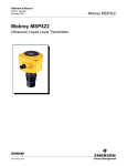
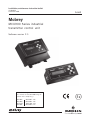
Installation, maintenance instruction leaflet
IP2030/IM
November 2005
Level
Mobrey
MCU900 Series industrial
transmitter control unit
Software version 2.0
MCU900 is the generic name used in
this manual for the MCU900 range of
control units comprising :MCU901
MCU902
MCULOG
MCU90F
www.mobrey.com
MCU901
MCU902
MCULOG
MCU90F
24V
24V
24V
24V
1
Safety Precautions
The following safety precautions should be observed before using this product or working on the attached
cables.
This MCU900 product is intended for use by qualified personnel who recognise shock hazards and are
familiar with the safety precautions required to avoid possible injury. Read the operating information
carefully before using the product.
The types of product users are:
Responsible body: This is the individual or group responsible for the use and maintenance of equipment,
and for ensuring that operators are adequately trained.
Operators use the product for its intended function. They do not require access to the electrical
connections within the control box, and would normally only operate the external keypad and monitor the
display.
Maintenance personnel perform routine procedures on the product to keep it operating, for example,
checking the line voltage or checking electrical connections, replacing mains fuses etc.
Service personnel are trained to work on live circuits, and perform safe installations and repairs of
products. Only properly trained service personnel may perform installation and service procedures.
However, the only serviceable part in MCU900 is the mains cartridge fuse.
Users of this product must be protected from electric shock at all times. Product users must be trained to
protect themselves from the risk of electric shock.
MCU900 Control Units are double insulated and do not require a mains earth.
Periodically inspect the connecting cables for possible wear, cracks, or breaks.
The fuse must only be replaced with same type and rating for continued protection against fire hazard.
To clean the instrument, use a damp cloth with a mild, water based cleaner. Clean the exterior of the
instrument only. Do not allow liquids to enter or spill on the instrument.
WARNING - If this equipment is used in a manner not specified by Mobrey Measurement, the protection
provided may be impaired. The MCU900 is regarded as permanently installed equipment and as such a
double pole switch or circuit breaker must be included in the installation. This should be in close proximity
to and not obstructed by the equipment. This must be marked as its disconnecting device.
Disconnect supply before removing cover.
The IP rating is only achieved when unit is correctly assembled with supplied parts and suitable cables.
Customer supplied glands must be suitable for application.
Under no circumstances must voltages higher than those stated in this manual be applied.
The installation of the MCU900 and its associated power cables must be such that tank overflow, local
flooding or pump failure do not cause these to be submerged or subject to flows of water. Sensors and
sensor cabling can be submerged without hazard to equipment operators when correctly connected as
described in this manual.
Explanation of symbols:
!
The I.S. earth terminal, marked
hazardous area systems.
= Refer to manual
must be connected to an external Intrinsically safe earth for all
CHECK THAT THE POWER SUPPLY IS SUITABLE BEFORE SWITCHING POWER ON.
Internal adjustments can select mains 115 Volts AC power, which makes the equipment unsuitable for
230V AC supplies. Check this Voltage selection switch is suitable set for the available power supply.
HAZARDOUS AREA SYSTEMS :Where the MCU900 is connected to a transmitter located in a hazardous area, additional instructions
apply. Refer to page 6 and safety instruction leaflet IP2030/SI.
The symbol
in the text of this manual refers the reader to page 6 and safety instruction leaflet
IP2030/SI as relevant.
2
CONTENTS
Page
1.
1.1
Product Introduction
Control Unit functions
4
4
2.
Mobrey MCU900 Series Controller
5
2.1
2.2
2.3
2.4
Display and keypad
Type numbering system
Safety data
Electrical Specifications
5
6
6
7
3.
3.1
3.2
3.2.1.
3.3.
3.3.1.
3.3.2.
3.4.
3.4.1
3.5.
3.6.
3.7.
3.8.
3.9.
3.10.
MCU900 Control Unit Installation
Environmental specification
MCU900W Wall Mounting models
Electrical connections : MCU900W Wall mounting models
MCU900P Panel Mounting models
Mounting in the panel
Electrical connections : MCU900P Panel mounting models
Notes on transmitter installation & cabling
Special notes for connecting HART transmitters
Power connection
Earthing
Relays
Current output
Digital control voltage free contact inputs
RS232
8
8
8
10
11
11
13
14
15
16
16
16
17
17
18
4.
Maintenance / Inspection
18
5.
Accessories
18
Appendices
Appendix 1 Introduction to programming the MCU900
Associated manuals
IP2040/QS Quickstart Manual covering use of the MCU900 with a
Mobrey ultrasonic transmitter
IP2041/QS Quickstart manual for Differential system
IP2030/OM Detailed technical programming and operating manual
IP2030/SI Safety Instruction Manual
IP2042/QS Quickstart manual for Logging system
Footnote :In this manual the following terms are used which refer to trademarks from other manufacturers:
HART: is the protocol adopted for the MCU900 SMART Communications.
HART is a registered trademark of the HART Communications Foundation and is a mnemonic for
Highway Addressable Remote Transducer.
3
1.0
Product Introduction
MCU900 is the generic family name for a range of industrial transmitter control units, providing a wide
range of control functions and a visual display of the measured variable. There are two mounting styles
available; a tough IP65 Wall mounting control unit for either indoor or outdoor installation, and a Panel
mounting control unit designed for direct mounting in a control panel. The controller will accept a
4-20mA signal from a self-powered transmitter or can provide 24V dc power to the transmitter if required.
A HART transmitter, powered from the MCU900, can be connected to the MCU900 and all Universal plus
some Common Practice commands will be implemented.
The MCU900 may be connected to a 4-20mA transmitter installed in a hazardous area. However, the
MCU900 is designed for mounting in a non-hazardous (safe) area.
Control functionality is provided by the 5 SPCO voltage free contact relays in the MCU900. There is also
an isolated 4-20mA signal out.
For applications where the functionality of the MCU900 is linked to other external events, 2 digital input
ports are provided to accept contact closure signals.
The MCU900 is simply programmed using the 6 key membrane keypad on the front of the unit. Menu
structured programming is employed, with the display assisting the user with dynamic help text.
1.1. Control Unit Functions
Using either a standard 4-20mA input or a digital HART input from a transmitter, the MCU900 control unit
will provide the following functions :
• Calculation and display of the MCU900 Primary Variable (PV).
The user can choose this to be the reading coming from the transmitter, which may be a depth or distance
measurement from a HART ultrasonic transmitter or may be a mA reading from a pressure transmitter, or
some other value calculated by the MCU900 based on the transmitter input, which could be a level,
distance, contents or flow reading. A totaliser function is also included.
The MCU900 is factory programmed with a set of standard volumetric and flow equations to convert a level
signal to contents or flow, and also has a 21 point user programmed look-up table for non-standard
applications.
MCU902 units calculated the difference, sum or product of 2 separate 4-20mA inputs.
MCULOG units have a 4800 event on board logging capability.
• 4-20mA signal out from the MCU900 control unit.
The MCU900 current output is usually proportional to the displayed PV, and is displayed in bargraph form
on the display (0-100%).
• Relay control functions.
There are 5 freely assignable relays. Relay 5 is a fault relay by default, which may be assigned to control
duty if required. The other 4 relays are available for the user to programme to operate at chosen values of
the displayed PV, or other calculated values.
The MCU900 is factory programmed with a selection of popular pump control routines for wet well and
sump control, along with energy saving over-rides.
• Voltage free (digital) contact input
Up to two voltage free contact closure inputs may be connected, allowing external over-ride of control unit
functions if desired.
• Programming a transmitter from the MCU900 control unit
As the MCU900 will communicate digitally with any HART compatible transmitter powered by the
MCU900, it is possible to programme a HART transmitter using the MCU900 keypad.
Full communication with Mobrey HART ultrasonic transmitters, allowing access to all transmitter
parameters is supported, whilst Universal and some Common Practice commands of other HART
transmitters is possible in accordance with HART protocol.
4
2.0 Mobrey MCU900 Series Controller
2.1 Display and Keypad
(Model MCU900P shown)
Figure 1 : MCU900 keypad and LCD display
Note : The keypad, display and operation are common to both Wall and Panel mounting options.
The MCU900 display is fully field
configurable and may be customised to
suit the requirements of the user.
Typically the 4 line display is as shown in
Figure 2, The top line shows whether the
programme lock is open together with the
time display. The actual measurement, the
MCU900 Primary Variable (PV) is displayed
in the centre using double height
characters. The lower line shows a
bargraph representation of the 4-20mA
current output of the control unit,
proportional to the PV, 0-100%.
IN1
IN2
O
O
-
RL1
15:02
5.64m
O
O
O
RL2
RL3
RL4
RL5
Figure 2 : Typical MCU900 liquid crystal display
Additional flags on the display show the status of the five relay outputs, RL1 to RL5, and of the digital
control inputs into the MCU900.
Keypad Operation :
There are 6 buttons on the MCU900 front panel. The four ARROWS allow navigation around the
programming menu and the " ESC" and "↵ " buttons allow movement from one screen to the next. By
pressing "ESC" repeatedly, the screen will always return to the normal display as shown in Fig 2.
Movement through the menu structure using the arrows is shown by the titles being "highlighted", ie
reversed to show white letters on a dark background. The LCD is backlit for operator convenience. (This
can be turned off if required).
Some basic introductory programming details are given in Appendix 1, whilst full programming and
operating instructions are given in Manual IP2030/OM. Quickstart manuals, are also available, covering
use of the MCU900, MCU902, MCULOG and MCU90F with a Mobrey ultrasonic transmitter(s).
5
2.2 Type Numbering System
MCU
Mobrey Control Unit
901
902
LOG
90F
Standard model
Differential model
Logging model
Open channel flow model
WX
PX
Wall mounting
Panel mounting
-A
-A24
ATEX certified, 115V ac/230V ac mains powered
24V dc powered
2.3 Safety Data
Type numbers
Certificate number
ATEX Coding
(EU Directive 94/9/EC)
See above
BAS00ATEX7064 and BAS01ATEX7225X
Cenelec Coding
[EEx ia] IIC -40°C ≤ Ta ≤ 55°C
II [1] G D
Safety Parameters
Terminal 1 (24V) w.r.t. terminal 2 (Iin)
Terminal 1 (24V) w.r.t. terminal 3 (Earth)
Terminal 2 (Iin) w.r.t. terminal 3 (Earth)
Ui
Uo
Io
Po
Li
Ci
Ui =
Ii =
Li =
Ci =
Uo =
Io =
Po =
=
=
=
=
=
=
0
28V
120mA
0.82W
0.2mH
0.6nF
30V
120mA
0.1mH
0.6nF
6.51V (Cap. charging only)
0
0
The capacitance and either inductance or inductance to resistance ratio L/R of the cable and equipment
connected to the intrinsically safe output terminals must not exceed the following values :
Group
Capacitance
Inductance
or
L/R Ratio
IIC
0.082*µF
1.2mH
42 µH/Ω
IIB
0.65µF
10.9mH
172 µH/Ω
IIA
2.15µF
21.9mH
346 µH/Ω
* 0.082µF of which total Ci of the hazardous area apparatus connected must not exceed 0.020µF.
Terminal 2 (IIN) w.r.t. Terminal 3 (Earth) must be treated as a 6.51V source. The 6.51V is considered as
being the theoretical maximum to which a capacitive load across these terminals could become charged
through leakage through internal series blocking diodes. This voltage does not contribute to the short
circuit sparking risk of any external source connected to these terminals.
6
2.4
Electrical Specifications
Cable Entry
5 x Ø 20mm, (3 blanking plugs, 2 cable glands)
Cable connections
Cage clamp terminal block, suitable for 2.5mm2 max cable.
Supply voltage
Switch selected :
Mains - 115Vac, voltage range 98Vac - 127Vac 50-60Hz
Mains - 230Vac, voltage range 196Vac - 254Vac 50-60Hz
DC - 24Vdc, voltage range 15Vdc - 30Vdc
Power consumption
Mains - 10VA at nominal supply voltage
Mains - 18VA Max.
DC - 9W max
Fuse
Mains - 200mA (T) 5 x 20mm 250V
Transmitter input
4-20mA (Earth referenced in MCU900)
CAT 1 30V dc Max.
Digital inputs
Unit accepts two trigger input signals.
(Voltage free contact closure)
Relay Outputs
5 x SPCO Relays, rated 5 Amp at 250 Vac Resistive
Please refer to section 3.7 for safety use.
Current Output
4-20 mA isolated into 1kΩ max.
If externally powered then max. voltage is 30Vdc
DC Power Output
24V DC for transmitter, 25mA max. load
HART
HART digital communications to transmitter
7
See "WARNING"
in section Safety
Precautions on
Page 2
3.0
MCU900 Control Unit Installation
The control unit must not be mounted in areas where an explosion hazard exists.
If connecting the MCU900 to a 4-20mA transmitter located in a hazardous area, refer also to
instructions on page 6 and in safety instruction leaflet IP2030/SI.
Refer also to the important safety precautions detailed at the start of this manual.
3.1
Environmental Specification
Ambient temperature
-40°C to 55°C
Max Altitude
2000m
Max Humidity
100% RH
Electrical Safety
Conforms to EN61010-1
Installation Category
III Supply voltage <127Vac
II Supply voltage <254Vac
Pollution Degree
2
3.2
MCU900W Wall Mounting models
The control unit housing is rated IP65. It is suitable for mounting outside, but this should be above any
flood level, away from any overflow water path, and away from direct sunlight. Do not mount the
MCU900W on a structure that is subject to vibration, or in a position where damage may be caused by
impact, thermal stress or liquid ingress.
The mass of the MCU900W is 1.4kg. To conform with safety requirements, the wall on which the
MCU900W is mounted should be capable of supporting 4 times this weight.
It is not necessary or advisable to remove the lid to the upper part of the box, containing the LCD and
keypad.There are no user serviceable parts inside. The control unit must not be modified in any way.
Mount the unit on a suitable wall or structure using the 3 fixing points as shown in figure 3. The most
convenient way is to position the central top fixing first, then hang the control unit on this. Use a spirit
level to ensure the unit is horizontal, then mark the two lower fixing positions on the wall. (These are
accessible once the terminal cover is removed).
The MCU900W is supplied with IP65 Nylon cable glands for connections to the field mounted transmitter
and the mains power supply. MCULOG has an additional connector which is used to download logged
data.
It is the responsibility of the user to ensure that cable glands and connection to the MCU900W is in
accordance with local or national standards.
8
Figure 3 : MCU900W Control Unit Dimensions
9
3.2.1 Electrical Connections : MCU900W Wall mounting models
All field wiring connections are accessible by removing the lower terminal cover, which is secured by two
screws. Note that it is the responsibility of the installer to observe all local regulations and approval
requirements, and to ensure wiring is suitable for the load current and the insulation is suitable for the
voltage, temperature and environment of the installation. Obtain and check any hazardous area work
permits required before applying power to the MCU900. On no account should the mechanical barriers
separating the terminal area from the main enclosure and the transmitter terminals from the other terminals
be removed or modified.
The diagram below shows the layout of external connection terminals: all terminal blocks are suitable for
wires 0.5mm2 to 1.5mm2 (2.5mm2 for mains terminals). Insulation should be stripped back 7mm.
Two cable glands, rated IP65 and suitable for cable with outside diameter 4mm to 7mm, are supplied for
use with the mains supply and transmitter cable. The three other connection positions are supplied with
M20 blanking plugs. All glands and plugs are supplied in a separate plastic bag. The installer must fit
these, or suitable equivalents, in place of the transit red-caps, to ensure weatherproofing of the MCU900.
Note that the white sealing washers supplied with the all cable glands and blanking plugs must be fitted
on the outside of the enclosure under the gland or blanking plug. It is the responsibility of the user to
ensure suitable cable glands or conduit connections are used when wiring to the MCU900 to maintain the
enclosure integrity. The 5 cable entry positions are pre-drilled to accept M20 cable glands. MCULOG has
a data download socket factory fitted in one of the positions.
Hazardous Area Connections
1
24V
2
I in
3
4
5
RX TX
6
7
8
9
0V 24V Iout 0V
10 11 12
IN1 IN2 0V
Figure 4:
13 14 15
NO COM NC
16 17 18
NO COM NC
19 20 21
NO COM NC
25 26 27
NO COM NC
28
L
22 23 24
NO COM NC
29
N
30
FUSE
200mA (T)
IS EARTH
Connection Terminal Layout (mains version shown)
Note that not all of the terminals are labelled on the pcb - a wiring label is positioned in the box.
The transmitter connections are on the left side of the terminal enclosure.
The I.S. Earth (Terminal 30) must be connected to an Intrinsically Safe Earth if the transmitter connected
to terminals 1 and 2 is located in a hazardous area.
Terminal
1
2
3
4-6
7-9
10-12
13-15
16-18
19-21
22-24
25-27
28-29
30
31
32
Function
Loop supply
Current Input
Screen
RS232
Current Output
Digital Input 1 & 2
Relay 1
Relay 2
Relay 3
Relay 4
Relay 5
Mains Input
IS Earth
Negative
Positive
Layout
24V
Iin
RX-TX-0V
24V- Iout-0V
IN1-IN2-0V
NO-COM-NC
NO-COM-NC
NO-COM-NC
NO-COM-NC
NO-COM-NC
L-N (mains version only)
- (DC version only)
+ (DC version only)
10
3.3.
MCU900P Panel mounting models
Do not mount the MCU900P on a panel that is subject to vibration, or in a position where damage may be
caused by impact, thermal stress or liquid ingress.
The MCU900P control unit is rated IP40 and is designed for panel mounting in a weatherproof
environment. An optional fascia overlay hood is available which improves the IP rating to IP65 (See
appendix 1).
A Rack mounting kit is available which allows mounting of an MCU900P in a standard 19” rack. Up to two
control units can be mounted in one rack; each MCU900P requires a mounting kit. (See appendix 1).
Where 3 or more MCU900P control units are fitted in the same cabinet or panel, ensure that there is
adequate air circulation to aid cooling. It is recommended that an air circulation fan be fitted.
The MCU900P requires at least 165mm clearance behind the mounting panel to avoid fouling.
Once mounted, all wiring is made at the rear of the unit using the two part terminal blocks provided.
A pre-wired logged data download socket suitable for front panel mounting is provided with MCULOG
control units.
3.3.1 – Mounting in the panel
Mount the control unit on a panel with thickness between 1.5mm to 10mm, ensuring the panel is strong
enought to support the 1.2kg weight of the MCU900.
Ensuring there is enough clearance behind the chosen position in the panel (165mm min.), cut a slot
138mm long by 68mm high (i.e. landscape or horizontal slot) in the panel and remove any rough edges.
Unpack the two screw clips provided. Identify the moulded lugs in the moulded recesses on each side of
the control unit (ignore the recesses on the top and bottom of the control unit).
Holding the screwdriver slot end of the threaded spindle of one of the screw clamps and looking at the rear
of the control unit, locate the screw clip frame on the side of the control unit and see how the 4 steel lugs
of the screw clamp frame locate on the moulded lugs of the control unit. Gently pull the screw clamp such
that the lugs engage with each other. (see Figure 5).
Figure5
Remove the screw clamp and slide the control unit into the panel, ensuring that the panel seal provided is
in place behind the control unit bezel.
Re-fit the screw clamps, one on each side of the control unit and tighten with a screwdriver to clamp the
control unit in place against the panel.
11
Figure 6 : MCU900P Control Unit dimensions (mains unit shown)
Panel mounting details
Panel cut-out: 138mm x 68mm
Allow 165mm clearance behind panel
3.2
Logged data download socket : MCULOG control units only.
Drill a hole Ø in the panel at a suitable location such that the socket flying
leads can be wired to terminals 4, 5 and 6 at the rear of the MCU900P.
See page13 for wiring instructions.
11.85
20.5 Ø
12
3.3.2 Electrical connections : MCU900P Panel mounting models.
All connections are made at the rear of the control unit using the two part terminal connectors provided.
Note that it is the responsibility of the installer to observe all local regulations and approval requirements,
and to ensure wiring is suitable for the load current and the insulation is suitable for the voltage,
temperature and environment of the installation. Obtain and check any hazardous area work permits before
applying power to the MCU900.
Figure 7 below show the layout of the terminal connections. Terminal blocks are suitable for wires 0.5mm2
to 2.5mm2. Insulation should be stripped back 7mm.
Note the protective shield surrounding the transmitter connection terminals (1 –3). On no account must
this shield be damaged or removed as it is an integral part of the Intrinsically Safe design of the
MCU900P.
The I.S. Earth (Terminal 30) must be connected to an Intrinsically Safe earth if the transmitter connected
to terminals 1 and 2 is located in a hazardous area.
1
24V
3
13 14 15 16 17 18 19 20 21
2
2
IS EARTH
Iin
CURRENT OUT
RS232
DIGITAL INPUT
IN1 IN2 0V RX TX 0V 24V Iout 0V
10 11 12
4
5
6
7
8
9
10 11 12 4
5
6
7
8
9
30
RELAY 5
RELAY 4
NO C NC NO C NC
22 23 24 25 26 27
13
NO
14
C
15 16
NC NO
RELAY 1
22 23 24 25 26 27
17
C
18
NC
19 20
NO C
RELAY 2
MAINS INPUT
230V
3
21
NC
RELAY 3
L
N
28
29
28 29
31 2
CURRENT INPUT
1
Figure 7
Connection descriptions
Terminal
1
2
3
4-6
7-9
10-12
13-15
16-18
19-21
22-24
25-27
28-29
30
31
32
Function
Loop supply
Current Input
Screen
RS232
Current Output
Digital Input 1 & 2
Relay 1
Relay 2
Relay 3
Relay 4
Relay 5
Mains Input
IS Earth
Negative
Positive
Data download socket
MCULOG control units
only:-
Layout
24V
Iin
RX-TX-0V
24V- Iout-0V
IN1-IN2-0V
NO-COM-NC
NO-COM-NC
NO-COM-NC
NO-COM-NC
NO-COM-NC
L-N (Mains version only)
Connect the flying leads
from the pre-wired socket
provided as follows :• 4 - White
• 5 - Red
• 6 - Black
RX
TX
OV
- (DC version only)
+ (DC version only)
Note that the plug/socket connectors are polarised to prevent inter changeability and incorrect connection.
13
3.4 Notes on transmitter installation and cabling
Connection of a transmitter to the MCU900 does not confer Intrinsic Safety on the transmitter. It is the
responsibility of the user to ensure any transmitter installed in a hazardous area is suitable for use and
certified accordingly for use in the hazardous area. The installation should be in accordance with a
recognised code of practice.
Check the parameters of the installed system of MCU900, transmitter, any loop devices and
interconnecting cable to ensure compliance with the individual product certificates and technical data
(Refer to page 6).
Particular attention must be given to the cable and the transmitter to ensure that the total capacitance and
inductance limits stated in the MCU technical data in Section 2.3 are not exceeded.
Cable joins are allowable in cabling to the transmitter provided that the joint is made within an IP20
(minimum) enclosure suitable for the environment, and that the wiring withstands a test voltage of 500V
r.m.s. to earth.
The maximum length of cable permissible between the transmitter and MCU900 is determined by the
limits imposed by the intrinsically Safe certificates of the instruments.
No other outputs from the MCU900 must be routed through a hazardous area unless protected by an
additional I.S. Barrier.
It is the responsibility of the user to ensure that any transmitter is installed in accordance with the
manufacturer's instructions supplied with the transmitter.
Cable between the MCU900 and the transmitter should be twisted pair shielded with the shield connected
to terminal 3 marked " " in the MCU900. The shield should be left unconnected at the transmitter
unless there is a terminal specifically provided for this purpose.
Cable runs should be separate from any high voltage or mains cables to avoid crosstalk or interference.
Multicore cable may be used provided that other cores carry only low voltage (24V dc nom) signals and
each pair of cores is individually shielded.
Loop powered transmitters must be connected to terminals 1 - 3 as shown below : (Note different
arrangement of terminals in MCU900W and MCU900P).
24V
1
>
+
Iin
2
<
-
3
Figure 8
The MCU900 is able to provide 24V dc to a transmitter with a max load of 25mA.
Separately powered transmitters must be connected to terminals 2 and 3 as shown below :
24V
1
Iin
2
<
+
3
>
-
Figure 9
14
3.4.1
Special notes for connecting HART transmitters (including MSP900SH-A transmitters) to the MCU902
Control Unit.
The MCU902 Control Unit takes the input from two HART transmitters and will perform various
calculations to create the sum, difference or product of the two inputs.
The transmitters must be HART compatible for the MCU902 to operate correctly.
Connection of the transmitters to the MCU902 may be by cabling both transmitter cables into the
MCU902 using the cable glands provided, or may be on a single cable using one of the cable glands
provided, with the two transmitters connected to this cable in a suitable local junction box.
Tx1
+
-
1
1
2
2
+
-
3
3
Junction
Box
Tx1
+
+
Tx2
Tx2
MCU902 to transmitter connection
For correct operation, each transmitter must be changed to “multi-drop” mode so that they can
communicate with the MCU902 through a common connection. Each transmitter must therefore have it’s
poll address changed from the factory default address of “0” to a unique address. The MCU902 is used to
achieve this, but this requires that the transmitters be connected in sequence as detailed below :a)
b)
c)
d)
e)
With the power supply turned off, connect the first transmitter to terminals 1-3 in the MCU902
control unit.
Check that the power selector switch is set to the correct voltage (115 or 230 V ac) on mains unit
and turn the power supply on.
The MCU902 will detect the transmitter and automatically change the poll address of the
transmitter from “0” to “1”. This transmitter will also be automatically allocated to Channel 1 of the
MCU902.
Note, the MCU902 control unit may also offer the user the opportunity to set the bottom reference
of the MSP900SH-A transmitter at this point, which may be done or ignored by pressing the “Esc.”
Key.
Turn the power supply off and connect the second transmitter, either at the same terminals 1-3 as
the first transmitter or at a local junction box, such that both transmitters are now connected.
Turn the power supply back on and the MCU902 will once again search for and detect any
transmitters connected. Once the second transmitter is found, the MCU902 will automatically
change the poll address from “0” to “2”, and the transmitter will also be automatically allocated to
Channel 2 of the MCU902.
Note, the MCU902 control unit may also offer the user the opportunity to set the bottom reference
of the MSP900SH-A transmitter at this point, which may be done or ignored by pressing the “Esc.”
Key.
Installation of the transmitters is now complete.
15
3.5 Power connection
If the MCU900 is powered by mains AC power, select the AC voltage as 230V or 115V using the voltage
selector slide switch.
If dc powered ensure the supply is adequate (15 - 30Vdc). Do not exceed 30Vdc.
A switch or circuit breaker should be installed in close proximity to the instrument, and labelled as such.
Although the MCU900 meets all European standards for surge immunity on power and signal lines, it is
recommended that lightning suppressors, such as made by Telematic Ltd., are fitted if local conditions
make this advisable.
3.6 Earthing
MCU900 control units are double insulated and DO NOT require a mains earth.
DO NOT connect a mains earth to terminal 30.
Terminal 30 is provided for use as an Intrinsically Safe (or functional) earth connection which MUST be
used when a transmitter is mounted in a hazardous area and is connected to terminals 1 & 2.
Terminal 3 is to be used for connection of the shield of the twisted pair transmitter cable when the
MCU900 is powering the transmitter. See Fig. 8 and 9. Note that this shield should be left unconnected
at the transmitter end unless there is a terminal provided specifically for this purpose.
3.7. Relays
The 5 voltage free contact relays are grouped in the following configuration :
MCU900W Wall Mount Control Unit
Relay 1 & 2
Group 1
Relay 3 & 4
Group 2
Relay 5
Group 3
MCU900P Panel Mount Control Unit
Relay 1, 2 & 3
Group 1
Relay 4 & 5
Group 2
The relay NO-C-NC labels represent the relay terminals in the de-energised state.
Note that, whilst each relay is individually double insulated, their arrangement is such that insulation
between relays in the same group is standard or 'basic' insulation.
Care must be taken in order to avoid the risk of electric shock. It is not allowed to use relays in the same
Group to control circuits with both mains and dc or low voltage circuits.
16
3.8
Current Output
The current output may be connected in internally powered mode or loop-powered mode.
See connections in Fig 10 below.
In Loop-powered mode an external power source is required. A minimum of 2.5V is required across
terminals 7 and 8 for correct operation. The external voltage must not be more than 30V dc.
24v
24v
7
7
Io
Io
8
+
8
+
Load
External
supply
-
0v
0v
9
9
+
Load
Internally powered
Loop powered
Figure 10 : Alternative current output configurations
3.9
Digital Control Voltage free contact inputs
There are 2 trigger inputs IN1 and IN2. The digital trigger input is connected as shown below:
IN
External
contact
closure
10 or 11
0V
12
Figure 11 : Connection for external trigger input
17
-
3.10 RS232
The RS232 connections (Terminals 4-6) may be used for exchanging data with a PC or handheld device.
The configuration of the Control Unit may be read or modified using an application such as Mobrey
H-Conf401 running on a PC.
For the MCULOG, the logged data is downloaded from the RS232 port via a socket connection provided,
using Mobrey LogView running on a PC.
4
5
6
Rx
Tx
0V
4.0 Maintenance / Inspection
CONTROL UNIT
No maintenance is required beyond occasional cleaning of the enclosure with a damp cloth. Solvents or
bleaches should not be used. Do not modify or attempt to repair the unit.
Check lid and glands are tight, also check unit for damage and if damaged do not use.
5.0. Accessories
Rack mounting kit for MCU900P Panel Mounting models.
Comprises one pre-cut aluminium panel, dimensions 128.5mm high x 213mm wide x 2.5mm thick predrilled and supplied with 4 captive screws and bushes to allow fitting in a standard 19" Rack. (3U x 42HP)
Specify Mobrey part number MSP-RMK1 (one per MCU900P)
IP65 Hood for IP65 sealing of MCU900P Panel Mounting models.
Comprises a transparent hood which is positioned over the fascia of the MCU900P and which is secured in
place when the control unit is clamped into the panel. Note that 2 extra clamps/clips are required as
detailed below.
Contact Bopla Gmbh and order :1 off hood
NGS74GHN – 37007400
1 off pair of mounting clips
NGS-NK – 37003000
Bopla GmbH
Tel: (49) 05223 969000
Fax: (49) 05223 969100
www.bopla.de for a list of local agents and distributors.
18
APPENDIX 1
Introduction to programming the MCU900
The following few pages give a brief introduction to programming the MCU900. More detailed information
is given in the Operation Manual IP2030/OM, available from Mobrey or by download from the
Mobrey Measurement website at www.mobrey.com.
A1 The MCU900 keypad and menu navigation
The 4 red/white arrow keys are used to move around the menu structure, and the yellow enter key to
confirm data input. The red Esc key allows a backward step to the previous screen.
Practice now using the keypad to customise the system settings in the MCU900. You may like to set the
date, time and language of the display.
• Press the enter key to display the Main Menu.
• Press the down arrow once to highlight “SETUP” and press the enter key. (Note the beep which
confirms each key press)
• Select “MCU CONTROL UNIT” and press the enter key to reveal the “SETUP” menu.
• Use the down arrow to move down the list. Note that there are more than the three items shown in the
list, as indicated by an arrow pointing down in the lower right of the screen. Highlight “SYSTEM” and
press the enter key.
• The SYSTEM menu comprises 6 items. Press the down arrow several times, or the right arrow once, to
highlight “SETTINGS” and press the enter key.
• Select “Time” and press the enter key. You may now edit the time if appropriate.
• Press the enter key which will highlight the first “hours” digit. Use the up and down arrows to select the
correct value then press the right arrow to move to the next digit. Continue until the time shown is
correct, then press the enter key to save the time shown. Press Esc to jump back to the “SETTINGS”
screen and select another setting to customise as appropriate, for example, display language.
• Once the MCU900 has been customised to your satisfaction, press the Esc key repeatedly to return to
the main display screen.
A2 Programming the MCU900 for your application
The MCU900 is capable of complex control functionality, much of which is specific to certain duties. To
programme the MCU900 for a specific application, it has to be told what the application is and then
certain application details to allow the MCU900 to perform the necessary calculations.
To assist the user in understanding MCU900 programming, it is convenient to imagine these application
specific data to be stored in memory locations called “Parameters”, each of which has a unique address.
Not all parameters are necessary for each application.
Programming the correct parameters for your particular application is made easy by Mobrey
“Wizards”, which navigate the user around the menu structure and request only the data needed for your
chosen application.
A listing of the MCU900 parameters, their location in the menu structure and their units / default values is
given at the rear of this manual. Also, the parameter listing for the Mobrey MSP900SH is given,
as this is a popular choice of transmitter to use with this MCU900 control unit.
You are strongly recommended to use these Wizards whenever possible.
Before the Mobrey wizards are explained in more detail, it is important that the user understands the input
to the MCU900 and what is being shown on the display.
19
A2.1 Understanding the input to the MCU900 and what is shown on the display.
The MCU900 may be used with either a 4-20mA transmitter or a digital HART transmitter.
A2.1.1 Using a transmitter with a standard 4-20mA output.
Any transmitter with a 4-20mA output may be connected to the MCU900.
Exactly what this 4-20mA represents is a function of the transmitter. The transmitter can not be re-ranged
by the MCU900.
For example, if a level transmitter designed to give a 4-20mA output over 5m is installed in a 3m deep
tank, the input to the MCU900 is going to be 4-13.6mA.
When a standard 4-20mA transmitter is connected, the MCU900 will recognise the input and the PV
shown on the main display will be in % of current input, where 4mA is 0% and 20mA is 100%.
Note, in the example above, the maximum current that the MCU900 will see will be 13.6mA, so the PV
on the display will only ever show 60% maximum.
It is possible to scale this input in the MCU900 and give a 4-20mA output from the MCU900.
A2.1.2 Using a HART compatible transmitter
Any HART compatible transmitter can be connected to the MCU900.
The MCU900 will recognise a HART transmitter and automatically start digital communications. The PV
shown on the display will be extracted directly from the transmitter, along with the associated
measurement units.
You will notice a small “~” icon next to the padlock in the upper left corner of the display which
shows digital communications are in operation.
A2.1.3 Using the MCU902
The MCU902 accepts inputs from two HART transmitters arranged in multi-drop mode.
Transmitters MUST BE HART compatible to be used with the MCU902. See Section 3.4.1.
A2.2 Using Mobrey Wizard assisted programming
With a transmitter connected and operating, you should now tell the MCU900 what duty it is to perform –
Wet well pump control, Level measurement, Contents measurement or Flow measurement.
•
•
•
Press enter and navigate to the Duty Wizard selection screen “SETUP / MCU900 CONTROL UNIT /
DUTY (mode) / Duty Wizard.
Press enter to start the duty wizard and select the duty for the MCU900
Enter data as requested by the MCU900, which will automatically set up the input scaling and current
output of the MCU900.
At the end of any duty wizard you will automatically be offered further wizards which are appropriate to
you chosen application. For example, the “MCU Relay WIZARD”, which allows you to set up relay control
or alarm points as required, or the “TOTALISER WIZARD” relevant to open channel flow measurement
and totalisation.
Further details of Mobrey Wizards are given in the system Quickstart manual IP2040/QS and
the technical manual IP2030/OM available on request or from the website.
20
A2.3 Useful programming information
The following information is given to assist users in programming other popular functions of the MCU900.
A2.3.1 Password protection
The MCU900 may be protected from unauthorised programming by setting a PIN number.
Follow the path “SETUP / MCU CONTROL UNIT / SYSTEM / SETTINGS / PIN” and enter a 4 digit PIN.
A2.3.2 Configure the display
The MCU900 display may be customised to show a variety of data. The display is sectioned into 3
horizontal zones, Upper, Middle and Lower.
Follow the path “SETUP / MCU CONTROL UNIT / OUTPUT / DISPLAY” and select which part of the
display you wish to customise. You may then select from a list of data which may be displayed there.
A2.3.3 Set up a digital input
Two voltage free contact inputs may be connected to the MCU900 and be programmed to cause certain
actions should they activate.
Follow the path “SETUP / MCU CONTROL UNIT / DIGITAL INPUT / Digital Input 1 “ and you can then
customise the input to suit your requirements.
A2.3.4 Commissioning aids
The MCU900 has several useful commissioning aids on-board.
Follow the path “SETUP / MCU CONTROL UNIT / SYSTEM / TEST “ and you can choose to autocycle the
MCU900 over the full range of the current input without changing the transmitter input or level in a tank,
trim input and output currents or use the MCU to drive a set output current into the loop.
A2.3.5 Re-setting default values
If the MCU900 is not operating as you would expect or you are unsure of some of the data you have
programmed in, you can re-set the MCU900 to it’s factory default condition. This action causes default
values to be loaded into all of the MCU900 parameter locations. Note, all previously entered data will be
overwritten or lost.
Follow the path “SETUP / MCU CONTROL UNIT / SYSTEM / DEFAULTS” and follow the instruction to load
defaults.
A2.3.6 Direct parameter access
Proficient users who become familiar with the parameter numbers of the MCU900 can access parameters
directly by parameter number.
Follow the path “DIRECT” and select either Pxxx or Dxxx. “D” type parameters are diagnostic parameters
and are read only.
Once a parameter number is entered and displayed, the user can use the up and down keys to scroll
through the full parameter list.
21
A2.3.7. Programming menus
A2.3.7.1 Menu structure and parameter list for the MCU901/MCULOG
Function Menu Option
Cancel Password
Go Offline ?
SETUP
Sub-menu Level 1
Sub-menu Level 2
Sub-menu Level 3
INPUT CHANNEL
Par No.
P111
P321
P112
P113
P114
P115
P116
P117
DUTY(Mode)
UNITS
P200
P201
P202
P203
P210
P240
P241
P242
P250
P251
P252
P253
P254
P255
P256
P257
P270
P271
P272
P273
P274
P275
P276
P277
P278
P340
P341
P342
P345
P346
P347
P400
P401
P402
PV DAMPING
CUSTOM
OVERRIDES
DIGITAL INPUT
DIGITAL INPUT 1
DIGITAL INPUT 2
OUTPUT
CURRENT OUTPUT
RELAY
RELAY 1
P410
P411
P412
P413
P414
P415
P420
P421
P422
P423
P424
P425
P430
P431
P432
P433
P434
P435
P440
P441
P442
P443
P444
P445
P450
P451
P452
P453
P454
P455
P490
P491
P492
P493
P494
P495
P496
P497
P498
RELAY 2
RELAY 3
RELAY 4
RELAY 5
ALARM
22
Parameter Name
Cancel Password
Go Online/Offline ?
Channel 1 Input Source
Current Input 1 Damping
Channel 1 Input Offset
Channel 1 Profile
Channel 1 Input Scale Factor
Channel 1 Non-Linear Data
Channel 1 Post Scale
Channel 1 Low Cut-off
Duty Wizard
PV Units
SV Units
TV Units
FV Units
Output PV Damping
Description
Message
Tag Number - Control Unit
Start On
Stop On
Stop If
Start Time
Interval
Start Time #2
Interval #2
Max Retries
Auto Sequence Enable
Auto Sequence Qualifier
Pump-down Relay
Pump-down Interval
Pump-down Duration
Energy Saving Start Time
Energy Saving Relay Select
Scum Line Prevention variance
Scum Line Prevention relay
Digital Input 1 Action
Digital Input 1 Delay
Digital Input 1 On State
Digital Input 2 Action
Digital Input 2 Delay
Digital Input 2 On State
Lower range value
Upper range value
Alarm action
Relay Wizard
Reset RL Params
Relay 1 Mode
Relay 1 PV ON Point
Relay 1 PV OFF Point
Relay 1 Minimum ON Time
Relay 1 Maximum ON Time
Relay 1 Minimum OFF Time
Relay 2 Mode
Relay 2 PV ON Point
Relay 2 PV OFF Point
Relay 2 Minimum ON Time
Relay 2 Maximum ON Time
Relay 2 Minimum OFF Time
Relay 3 Mode
Relay 3 PV ON Point
Relay 3 PV OFF Point
Relay 3 Minimum ON Time
Relay 3 Maximum ON Time
Relay 3 Minimum OFF Time
Relay 4 Mode
Relay 4 PV ON Point
Relay 4 PV OFF Point
Relay 4 Minimum ON Time
Relay 4 Maximum ON Time
Relay 4 Minimum OFF Time
Relay 5 Mode
Relay 5 PV ON Point
Relay 5 PV OFF Point
Relay 5 Minimum ON Time
Relay 5 Maximum ON Time
Relay 5 Minimum OFF Time
Rising level alarm delay
Relay operations
Relay operations relay select
Relay runtime
Relay runtime relay select
Pump efficiency limit
Pump Efficiency relay select
No activity delay
No activity relay
Units
Default
sec
as P201
s
hh.mm
hh.mm
hh.mm
hh.mm
hh.mm
hh.mm
hh.mm
mmm:ss
mmm:ss
as P200
as P200
-
Tx1 : PV
5
0
Scaled
1
0
1
AUTO
0
%
%
%
°C
0
as P200
as P200
mmm:ss
mmm:ss
mmm:ss
as P200
as P200
mmm:ss
mmm:ss
mmm:ss
as P200
as P200
mmm:ss
mmm:ss
mmm:ss
as P200
as P200
mmm:ss
mmm:ss
mmm:ss
as P200
as P200
mmm:ss
mmm:ss
mmm:ss
mmm:ss
hh.mm
hh:mm
-
MCU CONTROL
MESSAGE
MSP2000
None
None
None
07:00
01:00
00:00
00:00
10
Off
0
0
00:00
00:00
00:00
0
0
0
Free
000:00
Closed
Free
000:00
Closed
0
100
3.6mA
0
None
0
0
000:00
000:00
000:00
None
0
0
000:00
000:00
000:00
None
0
0
000:00
000:00
000:00
None
0
0
000:00
000:00
000:00
Fault
0
0
000:00
000:00
000:00
000:00
0
Disabled
00:00
Disabled
0
0
00:00
0
TOTALISER
P530
P531
P534
P535
P540
P541
P542
P543
P544
P545
P547
P548
P549
P550
P551
P560
P561
P562
P570
P571
P572
P573
P575
ALARM
RELAY
FAULT
DISPLAY
LOGGING
P590
P591
P592
P593
SYSTEM
TEST
AUTO-CYCLE
DISPLAY
CURRENT INPUT
CURRENT OUTPUT
DEFAULTS
COMMS
P710
P711
P712
P713
P714
P715
P716
P730
P731
P734
P735
P737
P740
SETTINGS
FIXED
HART
MONITOR
READINGS
ANSWERS
RELAY
RELAY OPERATIONS
RELAY RUN TIME
DIAGNOSTICS
CHANNELS
PUMP EFFICIENCY
DIRECT
P700
P701
P702
Pxxx
Dxxx
23
D750
D751
D752
D753
D760
D761
D762
D763
D764
D765
D800
D801
D802
D803
D804
D805
D806
D809
D811
D812
D813
D814
D815
D820
D821
D822
D823
D824
D825
D828
D830
D831
D835
D840
D842
D844
D845
D846
D848
D849
D851
D861
D862
D863
D864
Totaliser Wizard
Totaliser Factor
Totaliser Units
Totaliser Pulse width
Sampler Factor
PV Out of Limits
Current Output Saturated
Logging Memory Filling
Digital Input 1 Active
Maximum number of retries
Current Input Saturated
Rising level
Relay operations
Relay runtime
Pump efficiency
No activity
System Fault Alarm
Control Unit Temperature over Limits
Transmitter Fault
Display Select 1 (upper)
Display Select 2 (mid)
Display Select 3 (lower)
Decimal places
Backlight On/Off
Logging Wizard
Logging interval
Fast logging select mode
Do/Do not overwrite old data
Low Memory Alarm Threshold
Self Test
Display Test
4mA input adjust
20mA input adjust
4mA output adjust
20mA output adjust
Set Current
DEFAULTS
Comms Address
Interface Type
Baud Rate
No. of Start Bits
No. of Data Bits
Parity of Data
No. of Stop Bits
Date
Time
Date format
Keypad Sound On/Off
Language
Personal Identification Code
Xmtr Wizard
Model Code
Serial Number - Control Unit
Hardware Revision
Software Version
Manufacturer's Code
Unique ID
Universal Command Revision
Transmitter Spec. Command Rev.
Preamble Bytes
Flags
Primary Variable
Secondary Variable
Tertiary Variable
Fourth Variable
Ullage
% Current Output
Current output
Rate of Change
Relay 1 Operations
Relay 2 Operations
Relay 3 Operations
Relay 4 Operations
Relay 5 Operations
Relay Status
Relay 1 Run-Time
Relay 2 Run-Time
Relay 3 Run-Time
Relay 4 Run-Time
Relay 5 Run-Time
Totaliser 1 Value
Alarm report
Fault report
Digital input status
Current input
Current input %
Temperature of Control Unit
Time to next Pump Down
Logging Memory Free
Date of Last Change
Date of 1st Power-On
Channel 1 output
Pump efficiency RL1
Pump efficiency RL2
Pump efficiency RL3
Pump efficiency RL4
-
ms
min
as P200
%
mA
as P200
as P201
as P202
as P203
as P200
%
mA
PV/min
hh:mm
hh:mm
hh:mm
hh:mm
hh:mm
P531
mA
%
°C
hh:mm
%
dmy
dmy
P201
%
%
%
%
-
0
0
None
100
0
None
None
None
None
None
None
None
None
None
None
None
Both
None
Both
P731-Time
D800-PV
Bargraph
3
On
0
0
0 (=Off)
On
0
0
0
Log download
9600
1
8
Even
1
01/01/00
dd/mm/yy
On
English
0000
0
MCU902WX-A
000000
8
12
Sol. Mobrey
000000
5
1
5
1
0
0
0
0
0
None
None
--/--/---/--/--
A2.3.7.2 Menu structure and parameter list for the MCU902
Function Menu
Option
Cancel Password
Go Offline ?
SETUP
Sub-menu Level 1
PV CALCULATION
Sub-menu Level 2
Sub-menu Level 3
CHANNEL 1
P111
P112
P113
P114
P115
P116
P117
P121
P122
P123
P124
P125
P126
P127
P150
P151
P321
CHANNEL 2
DUTY(Mode)
>
>
>
>
UNITS
P200
P201
P202
P203
P210
P240
P241
P242
P250
P251
P252
P253
P254
P255
P256
P257
P270
P271
P272
P273
P274
P275
P276
P277
P278
P340
P341
P342
P345
P346
P347
P400
P401
P402
PV DAMPING
>
>
>
CUSTOM
OVERRIDES
DIGITAL INPUT
DIGITAL INPUT 1
DIGITAL INPUT 2
OUTPUT
Par No.
CURRENT OUTPUT
RELAY
RELAY 1
P410
P411
P412
P413
P414
P415
P420
P421
P422
P423
P424
P425
P430
P431
P432
P433
P434
P435
P440
P441
P442
P443
P444
P445
RELAY 2
RELAY 3
RELAY 4
24
Parameter Name
Cancel Password
Go Online/Offline ?
Channel 1 Input Source
Channel 1 Input Offset
Channel 1 Profile
Channel 1 Input Scale Factor
Channel 1 Non-Linear Data
Channel 1 Post Scale NLP
Channel 1 Low Cut-off
Channel 2 Input Source
Channel 2 Input Offset
Channel 2 Profile
Channel 2 Input Scale Factor
Channel 2 Non-Linear Data
Channel 2 Post Scale NLP
Channel 2 Low Cut-off
Output Mapping
MCU Fourth Variable Source
Current Input 1 Damping
Duty Wizard
PV Units
SV Units
TV Units
FV Units
Output PV Damping
Description
Message
Tag Number - Control Unit
Start On
Stop On
Stop If
Start Time
Interval
Start Time #2
Interval #2
Max Retries
Auto Sequence Enable
Auto Sequence Qualifier
Pump-down Relay
Pump-down Interval
Pump-down Duration
Energy Saving Start Time
Energy Saving Relay Select
Scum Line Prevention variance
Scum Line Prevention relay
Digital Input 1 Action
Digital Input 1 Delay
Digital Input 1 On State
Digital Input 2 Action
Digital Input 2 Delay
Digital Input 2 On State
Lower range value
Upper range value
Alarm action
Relay Wizard
Reset RL Params
Relay 1 Mode
Relay 1 PV ON Point
Relay 1 PV OFF Point
Relay 1 Minimum ON Time
Relay 1 Maximum ON Time
Relay 1 Minimum OFF Time
Relay 2 Mode
Relay 2 PV ON Point
Relay 2 PV OFF Point
Relay 2 Minimum ON Time
Relay 2 Maximum ON Time
Relay 2 Minimum OFF Time
Relay 3 Mode
Relay 3 PV ON Point
Relay 3 PV OFF Point
Relay 3 Minimum ON Time
Relay 3 Maximum ON Time
Relay 3 Minimum OFF Time
Relay 4 Mode
Relay 4 PV ON Point
Relay 4 PV OFF Point
Relay 4 Minimum ON Time
Relay 4 Maximum ON Time
Relay 4 Minimum OFF Time
Units
Default
as P201
as P202
sec
s
hh.mm
hh.mm
hh.mm
hh.mm
hh.mm
hh.mm
hh.mm
mmm:ss
mmm:ss
as P200
as P200
-
Tx1 : PV
0
Scaled
1
0
1
AUTO
Tx2 : PV
0
Scaled
1
0
1
AUTO
Ch1
Tx1 : FV
5
0
%
%
%
°C
0
MCU CONTROL
MESSAGE
MSP2000
None
None
None
07:00
01:00
00:00
00:00
10
Off
0
0
00:00
00:00
00:00
0
0
0
Free
000:00
Closed
Free
000:00
Closed
0
100
3.6mA
0
as P200
as P200
mmm:ss
mmm:ss
mmm:ss
as P200
as P200
mmm:ss
mmm:ss
mmm:ss
as P200
as P200
mmm:ss
mmm:ss
mmm:ss
as P200
as P200
mmm:ss
mmm:ss
mmm:ss
None
0
0
000:00
000:00
000:00
None
0
0
000:00
000:00
000:00
None
0
0
000:00
000:00
000:00
None
0
0
000:00
000:00
000:00
RELAY 5
P450
P451
P452
P453
P454
P455
P490
P491
P492
P493
P494
P495
P496
P497
P498
ALARM
TOTALISER
P530
P531
P532
P533
P536
P534
P535
P490
P491
P492
P493
P494
P495
P496
P497
P498
ALARM
TOTALISER
P530
P531
P532
P533
P536
P534
P535
P540
P541
P542
P543
P544
P545
P547
P548
P549
P550
P551
P560
P561
P562
P570
P571
P572
P573
P575
ALARM
RELAY
FAULT
FAULT
FAULT
DISPLAY
DISPLAY
DISPLAY
DISPLAY
DISPLAY
LOGGING
P590
P591
P592
P593
SYSTEM
TEST
TEST
TEST
TEST
TEST
TEST
TEST
DEFAULTS
COMMS
COMMS
COMMS
COMMS
COMMS
COMMS
COMMS
AUTO-CYCLE
DISPLAY
CURRENT INPUT
CURRENT INPUT
CURRENT OUTPUT
CURRENT OUTPUT
CURRENT OUTPUT
P700
P701
P702
P710
P711
P712
P713
P714
P715
P716
25
Relay 5 Mode
Relay 5 PV ON Point
Relay 5 PV OFF Point
Relay 5 Minimum ON Time
Relay 5 Maximum ON Time
Relay 5 Minimum OFF Time
Rising level alarm delay
Relay operations
Relay operations relay select
Relay runtime
Relay runtime relay select
Pump efficiency limit
Pump Efficiency relay select
No activity delay
No activity relay
Totaliser Wizard
Totaliser 1 Factor
Totaliser 1 Units
Totaliser 2 Factor
Totaliser 2 Units
Totaliser 2 Source
Totaliser Pulse width
Sampler Factor
PV Out of Limits
Current Output Saturated
Logging Memory Filling
Digital Input 1 Active
Maximum number of retries
Current Input Saturated
Rising level
Relay operations
Relay runtime
Pump efficiency
No activity
System Fault Alarm
Control Unit Temperature over Limits
Transmitter Fault
Display Select 1 (upper)
Display Select 2 (mid)
Display Select 3 (lower)
Decimal places
Backlight On/Off
Logging Wizard
Logging interval
Fast logging select mode
Do/Do not overwrite old data
Low Memory Alarm Threshold
Self Test
Display Test
4mA input adjust
20mA input adjust
4mA output adjust
20mA output adjust
Set Current
DEFAULTS
Comms Address
Interface Type
Baud Rate
No. of Start Bits
No. of Data Bits
Parity of Data
No. of Stop Bits
as P200
as P200
mmm:ss
mmm:ss
mmm:ss
mmm:ss
hh.mm
hh:mm
ms
mmm:ss
hh.mm
hh:mm
ms
min
as P200
%
mA
-
Fault
0
0
000:00
000:00
000:00
000:00
0
Disabled
00:00
Disabled
0
0
00:00
0
0
0
None
0
None
None
100
0
000:00
0
Disabled
00:00
Disabled
0
0
00:00
0
0
0
None
0
None
None
100
0
None
None
None
None
None
None
None
None
None
None
None
Both
None
Both
P731-Time
D800-PV
Bargraph
3
On
0
0
0
On
0
0
0
Log download
9600
1
8
Even
1
MONITOR
READINGS
SETTINGS
SETTINGS
SETTINGS
SETTINGS
SETTINGS
SETTINGS
>
FIXED
FIXED
FIXED
FIXED
FIXED
FIXED
FIXED
FIXED
FIXED
FIXED
ANSWERS
ANSWERS
ANSWERS
ANSWERS
ANSWERS
ANSWERS
ANSWERS
>
RELAY
RELAY
RELAY
RELAY
RELAY
RELAY
RELAY
RELAY
RELAY
RELAY
RELAY
>
>
>
>
P730
P731
P734
P735
P737
P740
HART
HART
HART
HART
HART
HART
RELAY OPERATIONS
RELAY OPERATIONS
RELAY OPERATIONS
RELAY OPERATIONS
RELAY OPERATIONS
>
RELAY RUN TIME
RELAY RUN TIME
RELAY RUN TIME
RELAY RUN TIME
RELAY RUN TIME
DIAGNOSTICS
CHANNELS
PUMP EFFICIENCY
DIRECT
Pxxx
Dxxx
26
D750
D751
D752
D753
D760
D761
D762
D763
D764
D765
D800
D801
D802
D803
D804
D805
D806
D809
D811
D812
D813
D814
D815
D820
D821
D822
D823
D824
D825
D828
D829
D830
D831
D835
D840
D842
D844
D845
D846
D848
D849
D851
D852
D861
D862
D863
D864
Date
Time
Date format
Keypad Sound On/Off
Language
Personal Identification Code
Xmtr Wizard
Model Code
Serial Number - Control Unit
Hardware Revision
Software Version
Manufacturer's Code
Unique ID
Universal Command Revision
Transmitter Spec. Command Rev.
Preamble Bytes
Flags
Primary Variable
Secondary Variable
Tertiary Variable
Fourth Variable
Ullage
% Current Output
Current output
Rate of Change
Relay 1 Operations
Relay 2 Operations
Relay 3 Operations
Relay 4 Operations
Relay 5 Operations
Relay Status
Relay 1 Run-Time
Relay 2 Run-Time
Relay 3 Run-Time
Relay 4 Run-Time
Relay 5 Run-Time
Totaliser 1 Value
Totaliser 2 Value
Alarm report
Fault report
Digital input status
Current input
Current input %
Temperature of Control Unit
Time to next Pump Down
Logging Memory Free
Date of Last Change
Date of 1st Power-On
Channel 1 output
Channel 2 output
Pump efficiency RL1
Pump efficiency RL2
Pump efficiency RL3
Pump efficiency RL4
-
as P200
as P201
as P202
as P203
as P200
%
mA
PV/min
hh:mm
hh:mm
hh:mm
hh:mm
hh:mm
P531
P533
mA
%
°C
hh:mm
%
dmy
dmy
P201
P202
%
%
%
%
-
01/01/00
dd/mm/yy
On
English
0000
0
MCU902WX-A
000000
8
12
Sol. Mobrey
000000
5
1
5
1
0
0
0
0
0
None
None
--/--/---/--/--
A2.3.7.3 Menu structure and parameter list for the MCU90F
Function Menu
Option
Cancel Password
Go Offline ?
SETUP
Sub-menu Level
1
Sub-menu Level
2
Sub-menu Level
Par No.
3
P111
P321
P112
P113
P114
P115
P116
P117
INPUT CHANNEL
DUTY(Mode)
P200
P201
P202
P203
P210
P240
P241
P242
P250
P251
P252
P253
P254
P255
P256
P257
P275
P276
P340
P341
P342
P345
P346
P347
PV CALCULATION
PV DAMPING
CUSTOM
OVERRIDES
DIGITAL INPUT
DIGITAL INPUT 1
DIGITAL INPUT 2
OUTPUT
CURRENT OUTPUT
P400
P401
P402
RELAY
RELAY 1
RELAY 2
RELAY 3
RELAY 4
RELAY 5
ALARM
P410
P411
P412
P413
P414
P415
P420
P421
P422
P423
P424
P425
P430
P431
P432
P433
P434
P435
P440
P441
P442
P443
P444
P445
P450
P451
P452
P453
P454
P455
P490
P491
P492
P493
P494
P497
P498
TOTALISER
P530
P531
P532
P533
P536
P537
P534
P535
27
Parameter Name
Cancel Password
Go Online/Offline ?
Channel 1 Input Source
Current Input 1 Damping
Channel 1 Input Offset
Channel 1 Profile
Channel 1 Input Scale Factor
Channel 1 Non-Linear Data
Channel 1 Post Scale NLP
Channel 1 Low Cut-off
Flow Wizard
PV Units
SV Units
TV Units
FV Units
Output PV Damping
Description
Message
Tag Number - Control Unit
Start On
Stop On
Stop If
Start Time
Interval
Start Time #2
Interval #2
Max Retries
Energy Saving Start Time
Energy Saving Relay Select
Digital Input 1 Action
Digital Input 1 Delay
Digital Input 1 On State
Digital Input 2 Action
Digital Input 2 Delay
Digital Input 2 On State
Lower range value
Upper range value
Alarm action
Reset Relay Parameters
Relay 1 Mode
Relay 1 PV ON Point
Relay 1 PV OFF Point
Relay 1 Minimum ON Time
Relay 1 Maximum ON Time
Relay 1 Minimum OFF Time
Relay 2 Mode
Relay 2 PV ON Point
Relay 2 PV OFF Point
Relay 2 Minimum ON Time
Relay 2 Maximum ON Time
Relay 2 Minimum OFF Time
Relay 3 Mode
Relay 3 PV ON Point
Relay 3 PV OFF Point
Relay 3 Minimum ON Time
Relay 3 Maximum ON Time
Relay 3 Minimum OFF Time
Relay 4 Mode
Relay 4 PV ON Point
Relay 4 PV OFF Point
Relay 4 Minimum ON Time
Relay 4 Maximum ON Time
Relay 4 Minimum OFF Time
Relay 5 Mode
Relay 5 PV ON Point
Relay 5 PV OFF Point
Relay 5 Minimum ON Time
Relay 5 Maximum ON Time
Relay 5 Minimum OFF Time
Rising level alarm delay
Relay operations
Relay operations relay select
Relay runtime
Relay runtime relay select
No activity delay
No activity relay
Totaliser Wizard
Totaliser 1 Factor
Totaliser 1 Units
Totaliser 2 Factor
Totaliser 2 Units
Totaliser 2 Source
Totaliser 2 Decimal Places
Totaliser Pulse width
Sampler Factor
SETUP (contd)
OUTPUT (contd)
ALARM
RELAY
FAULT
DISPLAY
LOGGING
SYSTEM
TEST
AUTO-CYCLE
DISPLAY
CURRENT INPUT
CURRENT OUTPUT
DEFAULTS
COMMS
FIXED
HART
READINGS
ANSWERS
RELAY
RELAY OPERATIONS
RELAY RUN TIME
DIAGNOSTICS
CHANNELS
DIRECT
P700
P701
P702
P710
P711
P712
P713
P714
P715
P716
P730
P731
P734
P735
P737
P740
SETTINGS
MONITOR
P540
P541
P542
P543
P544
P545
P547
P548
P549
P551
P560
P561
P562
P570
P571
P572
P573
P575
P590
P591
P592
P593
Pxxx
Dxxx
28
D750
D751
D752
D753
D760
D761
D762
D763
D764
D765
D800
D801
D802
D803
D804
D805
D806
D809
D811
D812
D813
D814
D815
D820
D821
D822
D823
D824
D825
D828
D830
D831
D835
D840
D842
D844
D846
D848
D849
D851
PV Out of Limits
Current Output Saturated
Logging Memory Filling
Digital Input 1 Active
Maximum number of retries
Current Input Saturated
Rising level
Relay operations
Relay runtime
No activity
System Fault Alarm
Control Unit Temp over Limits
Transmitter Fault
Display Select 1 (upper)
Display Select 2 (mid)
Display Select 3 (lower)
Decimal places
Backlight On/Off
Logging interval
Fast logging select mode
Do/Do not overwrite old data
Low Memory Alarm Threshold
Self Test
Display Test
4mA input adjust
20mA input adjust
4mA output adjust
20mA output adjust
Set Current
Load Defaults
Comms Address
Interface Type
Baud Rate
No. of Start Bits
No. of Data Bits
Parity of Data
No. of Stop Bits
Date
Time
Date format
Keypad Sound On/Off
Language
Personal Identification Code 1
Xmtr Wizard
Model Code
Serial Number - Control Unit
Hardware Revision
Software Version
Manufacturer's Code
Unique ID
Universal Command Revision
Transmitter Specific Cmd Rev
Preamble Bytes
Flags
Primary Variable
Secondary Variable
Tertiary Variable
Fourth Variable
Ullage
% Current Output
Current output
Rate of Change
Relay 1 Operations
Relay 2 Operations
Relay 3 Operations
Relay 4 Operations
Relay 5 Operations
Relay Status
Relay 1 Run-Time
Relay 2 Run-Time
Relay 3 Run-Time
Relay 4 Run-Time
Relay 5 Run-Time
Totaliser Value
Alarm report
Fault report
Digital input status
Current input
Current input %
Temperature of Control Unit
Logging Memory Free
Date of Last Change
Date of 1st Power-On
Channel 1 output
-
29
30
31
Installation, Maintenance Instruction Leaflet
IP2030/IM
November 05
Level
Mobrey Measurement
158 Edinburgh Avenue,
Slough, Berks, UK, SL1 4UE
T +44 (0) 1753 756600
F +44 (0) 1753 823589
[email protected]
www.mobrey.com
Mobrey SA-NV
Mobrey GmbH
Mobrey SA
Mobrey sp z o o
Mobrey AB
Belgium
Deutschland
France
Polska
Sverige
Mobrey Inc
19408 Park Row, Suite 320,
Houston, TX 77084 USA
T +281 398 7890
F +281 398 7891
[email protected]
www.mobrey.com
tel: 02/465 3879
tel: 0211/99 808-0
tel: 01 30 17 40 80
tel: 022 871 7865
tel: 08-725 01 00
© 2005, Mobrey. The right is reserved to amend details given in this publication without notice.
32
abcdef