1
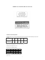
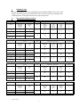
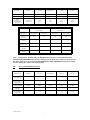
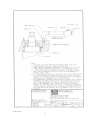
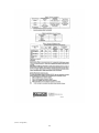
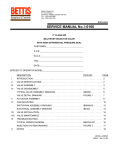
Bettis Canada Ltd.
4112-91A Street
Edmonton, Alberta
Canada T6E 5V2
Tel: 780-450-3600
Fax: 780-450-1400
SERVICE MANUAL No. I-0320
MULTIPORT FLOW SELECTOR
CUSTOMER:
P.O. #
W.O. #
TAG:
DATE:
OPERATOR MODEL
I-0320--.DOC/1
REV 1: AUG-31-04
(I-0320--.doc/1)
1
TABLE OF CONTENTS
I
INTRODUCTION ........................................................................................................................................... 4
II
MULTIPORT SPECIFICATIONS................................................................................................................ 4
IIB
ACTUATOR SPECIFICATIONS:................................................................................................................ 5
III
MULTIPORT INSTALLATION................................................................................................................... 6
IIIB
FIELD TECHNICIAN COMMISSIONING ACTIVITIES ........................................................................ 6
A.
REINSTALLATION OF THE ACTUATOR ASSEMBLY (also refer to section VII) ............................. 6
B.
HOME PORT CALIBRATION (I-0168/RD-00232 Section H)................................................................... 7
C.
MULTIPORT ELECTRONIC CONTROLLER SET UP........................................................................... 7
IV
MULTIPORT MAINTENANCE................................................................................................................... 8
V
MULTIPORT ASSEMBLY............................................................................................................................ 8
A.
BODY: (110) .................................................................................................................................................... 8
B.
PLUG: (130) .................................................................................................................................................... 8
C.
BONNET: (162)............................................................................................................................................... 9
D.
PLUG SEAL ADJUSTMENT (162): ........................................................................................................... 10
VI
MULTIPORT DISASSEMBLY................................................................................................................... 11
VII
ACTUATOR ASSEMBLY ........................................................................................................................... 11
A.
Pedestal, Connector, Speed Reducer, and Motor ....................................................................................... 11
B.
Local Stepping Command Electrical Conduit, Switchpak Pedestal, and Connector .............................. 12
VIII
TROUBLESHOOTING ............................................................................................................................... 13
IX
DRAWINGS .................................................................................................................................................. 14
X
TYPICAL MULTIPORT SEAL COMPONENTS ..................................................................................... 20
XI
MULTIPORT FLOW SELECTOR NOTES .............................................................................................. 23
APPENDIX 1: MOTORS............................................................................................................................................. 24
A: Baldor Motors..................................................................................................................................................... 24
B: Elnor Motors ....................................................................................................................................................... 27
C: Pacific Scientific Motors .................................................................................................................................... 32
APPENDIX 2: GEAR REDUCERS ............................................................................................................................ 36
A: Morse Gearbox ................................................................................................................................................... 36
B: Boston Gear Gearbox ......................................................................................................................................... 39
C: Baldor Gearbox .................................................................................................................................................. 47
Additional manuals:
Multiport Electronic Controller Model MP-08 – Service Manual I-0168
Multiport Electronic Controller Model MP-800 – Service Manual RD-00232
(I-0320--.doc/2)
2
OBSERVE ALL WARNING DECALS AND TAGS
MINIMUM TOOLS REQUIRED:
A torque wrench, socket wrench, and allen head wrenches are required to install the Multiport and Actuator
assembly.
NPS 2”
NPS 3”
ANSI 600
NPS 3”
ANSI
900/1500
NPS 4”
ANSI 600
NPS 4”
ANSI 900
1 7/16”
2”
2 3/8”
2 3/8”
2 9/16”
MULTIPORT SIZE
BONNET NUT
SOCKET SIZE
Other socket sizes required: 7/16", 1/2", 9/16", 3/4", 1 1/8".
Allen key sizes required: 5/32", 1/4".
Wrench sizes for Multiport flanges:
ANSI RATING
NPS 2
NPS 3
NPS4
NPS 6
NPS 8
300
1 1/16
-
600
1 1/16
1 1/4
1 7/16
1 5/8
1 13/16
900
1 7/16
1 13/16
1 13/16
2 3/16
1500
1 13/16
2
2 3/16
-
(I-0320--.doc/3)
3
I
INTRODUCTION
As many as eight flow-lines can be manifolded through one BETTIS Multiport Flow Selector. The
multiport allows diversion of an individual flow-line to a test outlet for testing or sampling, while
combining the flow of the other flow-lines into a separate group outlet.
II
MULTIPORT SPECIFICATIONS
RATING
SIZE
MAXIMUM
WORKING
PRESSURE
PSIG
WORKING
TEMP
ΕC
STD.
740
38
HIGH TEMP
600
260
STD.
740
38
HIGH TEMP
600
260
TRIM
RATING
TRIM
WORKING
TEMP
ΕC
STD.
1000
200
HIGH TEMP
1440
260
STD.
1440
38
HIGH TEMP
1200
260
STD.
1480
38
HIGH TEMP
600
260
RATING
WORKING
TEMP
ΕC
STD.
2220
38
HIGH TEMP
1795
260
STD.
2220
38
HIGH TEMP
1795
260
RATING
TRIM
ONE
TEST
OUTLET
PORT
ONE
GROUP
OUTLET
PORT
MULTIPORT
3x6
NPS 3
NPS 3
NPS 6
800
4x8
NPS 4
NPS 4
NPS 8
1275
ANSI 600RF CONNECTION
NPS
WORKING
TEMP
ΕC
STD.
3705
38
HIGH TEMP
2995
260
WEIGHT
ONE
TEST
OUTLET
PORT
ONE
GROUP
OUTLET
PORT
MULTIPORT
2x4
NPS 2
NPS 2
NPS 4
180
3x6
NPS 3
NPS 3
NPS 6
860
4x8
NPS 4
NPS 4
NPS 8
1375
ANSI 900RF CONNECTION
NPS
lbs.
WEIGHT
EIGHT
FLOWLINE
INLET
PORTS
ONE
TEST
OUTLET
PORT
ONE
GROUP
OUTLET
PORT
MULTIPORT
3x6
NPS 3
NPS 3
NPS 6
1800
4x10
NPS 4
NPS 4
NPS 10
3200
SIZE
MAXIMUM
WORKING
PRESSURE
PSIG
lbs.
EIGHT
FLOWLINE
INLET
PORTS
SIZE
MAXIMUM
WORKING
PRESSURE
PSIG
WEIGHT
EIGHT
FLOWLINE
INLET
PORTS
NPS
SIZE
MAXIMUM
WORKING
PRESSURE
PSIG
TRIM
ANSI 300RF CONNECTION
ANSI 1500RF CONNECTION
NPS
3x6
(I-0320--.doc/4)
4
lbs.
WEIGHT
EIGHT
FLOWLINE
INLET
PORTS
ONE
TEST
OUTLET
PORT
ONE
GROUP
OUTLET
PORT
MULTIPORT
NPS 3
NPS 3
NPS 6
1875
lbs.
MULTIPORT SIZE
AND RATING
NPS 2"
ANSI 600
NPS 3"
ANSI 600
NPS 3"
ANSI 900/1500
NPS 4"
ANSI 600
NPS 4"
ANSI 900
TEST OUTLETCV
67
151
100
270
218
GROUP OUTLET CV
262
594
429
1040
830
SHELL
HYDROSTATIC
TEST PRESSURE
PSIG (KPa)
2200-2220
(13780-15300)
2160
(14900)
5560
(38310)
2220
(15300)
3330
(22950)
MAXIMUM DYNAMIC DIFFERENTIAL
PSID @ 40ΕC
MULITPORT SIZE
AND RATING
STATIC STATIONARY DIFFERENTIAL
PSID @ 40ΕC
TEST-GROUP
GROUP-TEST
TEST-GROUP
GROUP-TEST
NPS 2X4
ANSI 600
600
550
1200
900
NPS 3X6
ANSI 60
500
450
1000
700
NPS 3X6
ANSI 900/1500
500
450
1000
700
NPS 4X8
ANSI 600
400
350
800
600
NPS 4X10
ANSI 900
400
350
800
600
Note: In Emergency situations only, the Multiport Flow Selector seal can maintain STATIC
STATIONARY DIFFERENTIAL pressure rating per specifications above. However, do not operate
the motor operator at greater than the MAXIMUM DYNAMIC DIFFERENTIAL pressure rating
because damage may occur to the motor operator.
IIB
ACTUATOR SPECIFICATIONS:
MULTIPORT SIZE
AND RATING
NPS 2"
ANSI 600
NPS 3"
ANSI 600
NPS 3"
ANSI 900/1500
NPS 4"
ANSI 600
NPS 4"
ANSI 900
PLUG POSITION
TOLERANCE
+/- 2Ε
+/- 2Ε
+/- 2Ε
+/- 2Ε
+/- 2Ε
BREAKAWAY
TORQUE @ MAX
DIFFERENTIAL
100-125 FT-LBS
100-170 FT-LBS
150-200 FT-LBS
150-210 FT-LBS
150-210 FT-LBS
ACTUATOR SPEED
1.4 RPM
1.4 RPM
1.4 RPM
1.4 RPM
1.4 RPM
ACTUATOR
WEIGHT
50 LBS
130 LBS
130 LBS
130 LBS
150 LBS
PLUG POSITION
ACCURACY
+/- 1Ε
+/- 1Ε
+/- 1Ε
+/- 1Ε
+/- 1Ε
(I-0320--.doc/5)
5
III
MULTIPORT INSTALLATION
Before installing the unit, observe all warning tags and:
1.
Check for external physical damage.
2.
Check for any visible leakage of gear oil from the speed reducer (426).
3.
Visually inspect the inside of the multiport through the group outlet port checking for damage,
rust, and debris.
4.
Check the wiring arrangement using the attached diagram on page 17 or as supplied for a
particular order/unit.
5.
Verify the voltage requirement of the motor (AC/DC) and connect power supply and signal
circuits to test the operation of the motor (438) and plug. Check for proper plug seal alignment at
each port.
NOTE: The Multiport Flow Selector plug seal/port alignment is factory adjusted when supplied with
actuator and should not require further adjustment.
6.
Connect piping.
NOTE: When hydrotesting external piping, position the plug between any two inlet ports in order to
equalize test pressure between the multiport body and external piping and prevent possible seal
damage from occurring.
IIIB
FIELD TECHNICIAN COMMISSIONING ACTIVITIES
Refer to the Multiport Electronic Controller service manual I-0168 for detailed commissioning activities.
CAUTION:
The valve body may be pressurized from hydrostatic testing - do not remove any bolts or flanges for
inspection until after the unit has been depressurized.
The connector and pointer are potential pinch points for fingers when the unit is rotating - keep
hands clear of the unit during operation.
Circuit boards are susceptible to damage from static discharge when touched - ensure that you
ground yourself before touching the JOG, ZERO, and HOME buttons on the electronic controller
board.
NOTE: Locate the reference mark (a centre punch mark) on the flat section of the stem to indicate
the orientation of the plug seal. The mark should be visible between the flats of the lower section of
the connector when assembly is completed and is to be used as a reference indicating the plug seal
location in the body (See photo, page 22).
A.
REINSTALLATION OF THE ACTUATOR ASSEMBLY (also refer to section VII)
NOTE: The indicator plate (402) must be set in place as the motor/gearbox is lowered onto the valve
body.
1.
Using a manual wrench, rotate the plug assembly two or three revolutions to verify that it turns
freely. Initial effort required to turn the plug may be high as the seal will typically acquire some
set from sitting for extended periods of time. Turn the plug until the reference mark is aligned
(I-0320--.doc/6)
6
with the #6 well connection. This allows for the installation of the connector pin. Note that
installing the pin may require electrical power so that the upper section of the connector can be
rotated to align the bolt hole.
2.
Install the lower section of the connector onto the stem flat. Orient the lower section of the
connector so that the indented mark is visible between the flats.
3.
Install the two studs (1/2NC) diagonally opposite one another (180° apart).
4.
Lower the actuator assembly over the studs, placing the indicator plate over the studs. Lower the
actuator assembly until it rests on the bonnet.
5.
Install the two bolts (1/2NC X 1.25LG) to secure the assembly to the bonnet.
6.
Install the lower nuts on the studs.
7.
Tighten all bolts and nuts finger tight only.
8.
With the connector sections aligned, install the connector bolt. Note that this may require
electrical power to rotate the connector and align bolt holes.
9.
Install the spacers, indicator plate, and upper nuts on the studs. Leave the nuts loose, to be
tightened later when alignment is completed (step 11, below).
10. Wrench tighten the two bolts and lower nuts.
NOTE: Refer to electrical drawings and wiring diagrams for electrical power terminal connection
and motor voltage.
11. After connecting power to the motor, rotate the plug two revolutions to align the connectors.
Visually check for any binding and adjust as necessary. After ensuring correct alignment, wrench
tighten all bolts and nuts.
B.
HOME PORT CALIBRATION (I-0168/RD-00232 Section H)
1.
Using the JOG button, align the connector sections to install the connector bolt and tighten the
connector set screw.
2.
If possible, remove the blind flange on the home port (port #8) and use the JOG button (tap briefly
for fine movement of the plug) on the controller circuit board to “fine tune” the plug seal/port
alignment.
3.
Follow the procedure in the Multiport Electronic Controller Manual for home port calibration (set
zero).
4.
When finished, align the hex corner of the lower connector with the appropriate slot on the
indicator plate. The pointer should also line up with the slot on the indicator plate.
5.
If the unit has the optional local control push button station, select step mode and press the button.
The plug should move automatically to the next available port and slowly step into position.
Verify this by observing the hex connector and the slot in the indicator plate.
MULTIPORT ELECTRONIC CONTROLLER SET UP
C.
Refer to the MEC service manual I-0168 for detailed instruction on:
1.
Disabling port positions (I-0168 Section I).
(I-0320--.doc/7)
7
2.
Controller address (I-0168 Section J).
3.
Control room MODBUS RTU operation (I-0168 Section D).
4.
Installation and use of Bettis Multiport Electronic Controller software on laptop PC.
MULTIPORT MAINTENANCE
IV
Refer to the typical multiport assembly drawing AB0461 on page 14 and the multiport cutaway drawing
AB0462 on page 15.
The Multiport Flow Selector is shipped completely greased and lubricated, but it is recommended that the
unit be checked prior to operation if it has been stored for more than one year. If required, lubricate with a
suitable injection lubricant (Sealweld D-1014 is recommended).
1.
Check speed reducer oil at regular intervals and change the oil each one hundred running hours or
once a year, whichever comes first. Use a suitable synthetic gear oil (Mobil Synthetic SHC-634
ISO VG460 lubricant is recommended).
2.
Make sure the oil in the speed reducer (426) is at the indicated level.
NOTE:Excessive oil could cause pressure build-up, leakage and overheating which will result in
rapid wear of the oil seals, bearing and gears.
3.
Lubricate bearing (160) through grease nipple every six months, or as needed. Use Dow Corning
Extreme High Temp #41 grease or a suitable equivalent.
4.
Do not lubricate the motor: it is a sealed unit.
5.
Monitor seals annually, adjusting if required (see section V-D. below) and replace seals every five
years or when leakage occurs.
MULTIPORT ASSEMBLY
V
Refer to the typical multiport assembly drawing AB0461 on page 14 and the multiport cutaway drawing
AB0462 on page 15.
Ensure all parts are clean and in good condition before assembling the Multiport Flow Selector. Use ESSO
Valve Grease No. 1 or a suitable equivalent to lubricate the components.
A.
BODY: (110)
1.
Visually inspect all internal and external surfaces and threads.
2.
Lubricate and install the 25% C/PTFE bushing (120) into the lower section of the body.
B.
PLUG: (130)
1.
Lubricate and install the lower plug o-ring (133), with the correct number of PTFE backup rings
(136). For ANSI 300/600 rated Multiports, install one PTFE backup ring above (on the side
nearest to the bonnet) the o-ring. For ANSI 900/1500 rated Multiports, install two PTFE backup
rings - one on either side of the lower plug o-ring.
2.
Lubricate and install the seal adjusting nut (138) by turning it clockwise (ie. viewing toward the
plug centerline) until solid. Follow with the seal wave springs (140). Ensure that the seal wave
springs are properly aligned and seated on the seal adjusting nut.
(I-0320--.doc/8)
8
NOTE:If the seal wave springs are not properly aligned and seated the plug seal may not hold rated
differential pressure.
3.
Install the seal back-up plate (143) against the shoulder in the plug.
4.
Lubricate and install the plug seal o-ring (149) on the stainless steel portion of the plug seal
assembly (142). Lubricate and install the plug seal assembly into the plug with the plug seal o-ring
properly positioned.
NOTE:Press seal assembly into the plug using hand force only, taking care not to damage seal
assembly.
5.
Install the correct number of scraper wave springs (158) followed by the scraper (154) into the
plug over the seal assembly. For NPS 2" Multiports, install two scraper wave springs. For NPS
3" and NPS 4" Multiports, install one scraper wave spring.
NOTE:Lubricate the spring and scraper so that they stay in place in the plug during assembly.
Ensure that the scraper fits freely into the plug. Check by pushing the scraper into the plug using
both hands then letting go to see if it returns to its original position.
6.
Ensure that the plug bushing (120) has been lubricated and installed into the lower section of the
body.
7.
Lower the plug (130) vertically into the body ensuring that the plug seal assembly (142) and
scraper (154) clear the body (110) bore. When installed, the plug (130) rests on top of the bushing
(120).
8.
Grease the tapered bearing cone and rollers (160) and install onto the plug.
C.
BONNET: (162)
1.
Lubricate and press fit the bearing cup (160) into the bonnet.
2.
Lubricate and install the correct number of PTFE backup rings (170) and the upper plug o-ring
(167) into the bonnet bore’s upper groove. For ANSI 300/600 rated Multiports, install one PTFE
backup ring above the upper plug o-ring. For ANSI 900/1500 rated Multiports, install two backup
rings - one on either side of the upper plug o-ring.
3.
Lubricate and install the upper plug polypak (164) into the bonnet (polypak is not required for
NPS 2" or NPS 3" ANSI 300/600 Multiports).
4.
Lubricate and install the bonnet o-ring (173) into the bonnet’s outer groove.
5.
From the bonnet’s top surface, lubricate and install the wiper (171) and grease fitting (178).
NOTE:Pump grease through the grease fitting (178) to fill the bearing bore.
6.
For NPS 3" ANSI 900/1500 and all NPS 4" Multiports, install the injection nipple (177), 90°
elbow (175), nipple, ball valve (174) and vent plug (176), ensuring that they are clean and well
oiled.
7.
Position the bonnet onto the Multiport body. For NPS 2" and NPS 3" ANSI 300/600 Multiports,
set the bonnet in place with the actuator mounting holes straddling the centreline of the group
outlet port. Use two lifting eyes installed into the jacking screw holes provided in the bonnet for
NPS 3" ANSI 900/1500 (3/4 NC) and all NPS 4" (1/2 NC) Multiports to vertically lift and set the
(I-0320--.doc/9)
9
bonnet in place on the multiport body with the seal injection fitting over the group outlet. The
bonnet stud holes must be aligned with the body’s tapped stud holes.
NOTE:Ensure the bonnet is flat and lowered slowly onto the top of the multiport body in order to
prevent damaging the body o-ring and plug seals. Push the bonnet down by hand or rubber mallet
only.
8.
Install the bonnet studs (180). Use Jet-Lube Kopr-Kote anti-seize lubricant or a suitable
equivalent.
9.
For NPS 4" ANSI 600/900 and NPS 3" ANSI 900/1500 Multiports, install the two lifting lugs
(179) 90° from the group outlet.
NOTE:The actual lifting lug position is 90° from the position shown in the typical assembly drawing
on page 8.
10. Tighten two of the bonnet nuts (182) at 180° interval. Then ensure that the plug (130) rotates
freely through one revolution.
11. Install and tighten the remaining nuts (182) after confirming that the bonnet (162) and plug (130)
have been centred. Torque the nuts to:
MULTIPORT SIZE
AND RATING
NPS 2”
ANSI 300/600
NPS 3”
ANSI 300/600
NPS 3”
ANSI 900/1500
NPS 4”
ANSI 600
NPS 4”
ANSI 900
D.
BONNET NUT TORQUE
FT-LBS
100
250
325
450
625
PLUG SEAL ADJUSTMENT (162):
1.
Adjust the plug seal assembly (142) by aligning the plug (130) with an open ( home test) port and
turning the adjusting nut (138) counter clockwise with the adjusting tool (viewing toward the plug
centerline) until the scraper (154) touches the inside wall surface. As the scraper approaches the
wall surface the seal wave springs will be compressed and the adjusting nut will have increased
resistance to turning.
2.
Rotate the plug (130) at least one complete revolution to check for binding or excessive turning
torque. Tighten the seal adjusting nut (138) counter clockwise (viewing towards the plug
centerline) to the appropriate torque value with the supplied adjusting tool.
MULTIPORT SIZE
AND RATING
NPS 2”
ANSI 300/600
NPS 3”
ANSI 300/600
NPS 3”
ANSI 900/1500
NPS 4”
ANSI 600
NPS 4”
ANSI 900
PLUG SEAL TORQUE
FT-LBS
30
35
30
40
40
NOTE: Do not over tighten the seal adjusting nut (138), as damage to the plug seal assembly may
result.
(I-0320--.doc/10)
10
3.
Turn the plug (130) at least one complete revolution while checking for smooth movement. If the
plug seal assembly (142) is binding at inlet ports when the plug is rotated, the plug seal assembly
or the seal wave springs (140) are not in their proper position(s). See disassembly procedure
below, if required.
4.
Install the two bonnet vent plugs (176).
5.
Perform any required leakage test(s).
MULTIPORT DISASSEMBLY
VI
Refer to typical multiport assembly drawing AB0461 on page 14, and the multiport cutaway drawing
AB0462 on page 15.
NOTE: The bonnet can be removed with the motor and gearbox still attached as one unit. When
doing so, place a reference mark on the plug and connector before removal to ensure that they are
replaced in the same position when the bonnet, motor, and gearbox are re-installed.
1.
Ensure that both the group and test pressures are zero before proceeding.
2.
Open a home test port for access to the seal assembly. Turn the seal adjusting nut (138) clockwise
until solid (viewing toward plug centerline) in order to release the spring load from the plug seal
assembly and provide clearance for the scraper in the body.
3.
Remove the bonnet nuts (182) and studs (180). Lift the bonnet vertically until it is clear of the plug
and body. Lifting eyes can be installed in the jacking screw holes provided in the bonnet for
some NPS 3" (3/4" NC) and NPS 4" (1/2" NC) Multiports. Set the bonnet aside.
4.
Remove the plug (130), complete with all seal components, from the multiport body.
5.
Disassemble the plug and plug seal and inspect all components. Reassemble following Multiport
Assembly procedure. The seal can be removed using the adjusting tool as follows:
i)
ii)
6.
Insert the tool into the seal adjusting nut and turn it counterclockwise until it disengages from
the final thread on the plug/rotor body.
Use the tool as a slide hammer on the back of the seal adjusting nut to pull the seal assembly
out of the plug/rotor body.
Removal of the bearing cup from the bonnet may require the use of a square stem puller and/or dry
ice (to shrink and loosen the bearing cup).
VII
ACTUATOR ASSEMBLY
A.
Pedestal, Connector, Speed Reducer, and Motor
Refer to typical assembly drawing AB0461 on page 14 and the typical controller assembly drawing
AB0463 on page16.
1.
Set the speed reducer pedestal (400) in place. Align motor for correct orientation.
2.
Install two bolts (404), two lockwashers (406), two spacers (401), two studs (403), and four nuts
(405) with the indicator plate (402). The two bolts must be installed opposite each other (180°
apart) so that the indicator plate can be mounted on the studs and spacers.
3.
Install the lower connector (408).
(I-0320--.doc/11)
11
NOTE: An index mark on one flat on the square end of the plug (130) indicates port position. Install
the connector so that the index mark is visible.
4.
Install the indicator (188) on the upper connector (410) using the nut (192). Ensure that the
indicator is aligned with the index mark on the square end of the plug.
5.
Place the upper connector (410) on the lower connector with the setscrew (413) started but without
the connector bolt and locknut.
6.
Install the speed reducer (426) onto the pedestal with the key (418) and four bolts (432),
lockwashers (436), and nuts (434).
7.
Install the motor (438) onto the speed reducer with four bolts and lockwashers. Ensure that the key
is in place before aligning and tightening the motor mounting bolts (refer to motor and gear
reducer product info for specific installation and maintenance instructions).
8.
Check for free rotation between the connector halves to confirm shaft alignment. This can be done
by turning the gear reducer by hand (or by using the electric motor) with the connector parts and
bolts loosely installed. Adjust the position of the connector halves if necessary.
NOTE: Use caution and keep hands away from all rotating parts if operating the electric motor to
check alignment.
9.
Tighten all mounting bolts and nuts
10. Install and tighten the lower connector bolt and locknut and tighten the setscrew (413).
B. Local Stepping Command Electrical Conduit, Switchpak Pedestal, and Connector
Refer to the typical electrical assembly drawing AB0463 on page 16. Note that the assembly details may
vary according to local regulations (i.e. use of cable instead of conduit).
1.
2.
3.
Set the Switchpak pedestal (448) on top of the speed reducer body and install four studs (452),
four lockwashers (453) and four nuts (454).
Install the Switchpak connector (457) on the speed reducer shaft followed by the Switchpak
coupling (455) and the Switchpak coupling adapter (459).
4.
Install the Switchpak (300) onto the Switchpak pedestal.
5.
Install the four Switchpak bolts (458) and lockwashers (462).
6.
Off the Switchpak pedestal assemble the push button station (350), local/remote switch (357), and
jog push button (356). Loosely install the push button station bolt (351), lockwasher (354), and nut
(352). If required, use the spacer (358) to fill the gap between the pushbutton station and the
Switchpak pedestal.
7.
Install all wiring, conduit, and seals according to the electrical diagram and local regulations.
8.
With connector parts loosely installed, rotate the shaft (either by hand or using the motor) and
check for proper alignment of the connector halves. Adjust if any binding is detected.
9.
Tighten all mounting bolts, nuts, and setscrews.
NOTE: Ensure that the connector setscrew seats against the flat section of the Switchpak shaft.
(I-0320--.doc/12)
12
VIII
A.
TROUBLESHOOTING
Actuator Does Not Align Plug (130) to Port.
1.
Check the multiport/actuator connector for looseness.
2.
Check the Switchpak/actuator connector for looseness.
3.
Check the motor for stalling or overload.
4.
Check the speed reducer for visual leakage or noisy gear.
5.
Check the accuracy of the position encoder itself (see manual RD-00232, “MultiPort Electronic
Controller with MP-800 Board).
6.
Refer to the Multiport Electronic Controller service manual (RD-00232) for port calibration
procedures.
B.
Plug Seal Assembly Leaks.
1.
Refer to specification for rated differential pressure limitations.
2.
Check the indicator plate and pin to ensure that the plug is aligned with the port .
3.
Check the seal for damage (CAUTION: Ensure that all pressures in the Multiport body, group
outlet, and test port are ZERO before visually checking the seal). With the multiport selector and
piping at zero pressure, remove the test port blind flange and visually check for plug seal assembly
damage (ie. Scratches) as the plug seal passes the test port .
4.
If more information is required contact the factory.
C.
Plug to Bonnet Stem Seal Leaks to Atmosphere.
NOTE: This section applies to NPS 3" ANSI 900/1500 and NPS 4" Multiports only.
Refer to the injection system drawing I-0240 on page 18. Recommended sealant is Sealweld D-1014 or
equivalent.
1.
The Multiport Flow Selector is shipped with the service valve (174) in the normally closed
position.
2.
To determine if the primary seal has failed, remove the vent plug (176) from the service valve and
gradually open it. Any leakage occurring past the primary seal will drain out of the open service
valve.
3.
If more information is required, contact the factory.
(I-0320--.doc/13)
13
IX
DRAWINGS
(I-0320--.doc/14)
14
(I-0320--.doc/15)
15
(I-0320--.doc/16)
16
(I-0320--.doc/17)
17
(I-0320--.doc/18)
18
(I-0320--.doc/19)
19
X
TYPICAL MULTIPORT SEAL COMPONENTS
PLUG SEAL COMPONENTS
SEAL ASSEMBLY (L–>R: BACKUP PLATE, O-RING, SEAT RING, SEAL INSERT, ASSEMBLY)
(I-0320--.doc/20)
20
SEAL ASSEMBLY (TOP: ASSEMBLY. BOTTOM (L–>R): SEAL ADJUSTMENT NUT, SEAL WAVE
SPRINGS, SEAT RING/PLATE/O-RING/SEAL INSERT, SCRAPER WAVE SPRINGS, SCRAPER)
PLUG SEAL ADJUSTMENT TOOL SHOWN WITH BASE PARALLEL TO SHANK FOR
INSERTION, BASE PERPENDICULAR TO SHANK, AND ENGAGED IN SEAL ADJUSTMENT NUT.
(I-0320--.doc/21)
21
PLUG (Index mark can be found on the stem flat that faces the same way as the plug seal opening.)
PLUG SEAL ADJUSTMENT TOOL IN PLUG
(I-0320--.doc/22)
22
XI
MULTIPORT FLOW SELECTOR NOTES
(I-0320--.doc/23 orig:ss/ss-2004-02-09 rev1:ss/ss-2004-08-31 app
23
DIST:(EF)O; (SM)P)
APPENDIX 1: MOTORS
A: Baldor Motors
(I-0320--.doc/appendix)
24
(I-0320--.doc/appendix)
25
(I-0320--.doc/appendix)
26
B: Elnor Motors
(I-0320--.doc/appendix)
27
(I-0320--.doc/appendix)
28
(I-0320--.doc/appendix)
29
(I-0320--.doc/appendix)
30
(I-0320--.doc/appendix)
31
C: Pacific Scientific Motors
(I-0320--.doc/appendix)
32
(I-0320--.doc/appendix)
33
(I-0320--.doc/appendix)
34
(I-0320--.doc/appendix)
35
APPENDIX 2: GEAR REDUCERS
A: Morse Gearbox
(I-0320--.doc/appendix)
36
(I-0320--.doc/appendix)
37
(I-0320--.doc/appendix)
38
B: Boston Gear Gearbox
(I-0320--.doc/appendix)
39
(I-0320--.doc/appendix)
40
(I-0320--.doc/appendix)
41
(I-0320--.doc/appendix)
42
(I-0320--.doc/appendix)
43
(I-0320--.doc/appendix)
44
(I-0320--.doc/appendix)
45
(I-0320--.doc/appendix)
46
C: Baldor Gearbox
(I-0320--.doc/appendix)
47