1
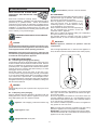
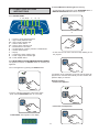
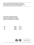
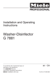
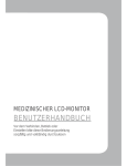
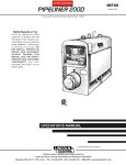
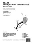
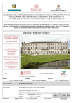
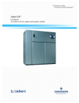
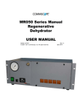
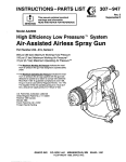
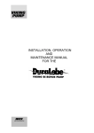
INSTALLATION, OPERATING AND MAINTENANCE INSTRUCTIONS
ISTRUZIONI DI INSTALLAZIONE, FUNZIONAMENTO E MANUTENZIONE
INSTRUCTIONS D'INSTALLATION, D'UTILISATION ET DE MAINTENANCE
INSTRUCCIONES DE INSTALACIÓN, USO Y MANTENIMIENTO
"PROSTORE SMART" VERTICAL REFRIGERATORS
FRIGORIFERI VERTICALI "PROSTORE SMART"
RÉFRIGÉRATEURS VERTICAUX "PROSTORE SMART"
FRIGORÍFICOS VERTICALES "PROSTORE SMART"
USA
IT
FR
ES
Page
Pagina
Page
Página
07
20
33
46
-19
- 32
- 45
- 58
PART NO. 5957 410 01
VERSION 2 2005.12
INSTALLATION DIAGRAM
SCHEMA DI INSTALLAZIONE
SCHÉMA D'INSTALLATION
DIAGRAMA DE INSTALACIÓN
105.66 Gallons / 400 Liters
105,66 Galloni / 400 litri
105,66 gallons / 400 litres
105,66 galones / 400 litros
23 5/8"
23 27/64"
2 3/4"
600 mm
595 mm
70 mm
12 51/64"
325 mm
I
83 5/32"
2112 mm
7 7/8"
200 mm
2 7/8"
73 mm
53/64"
21 mm
17 7/8"
454 mm
2 7/8"
73 mm
2 13/64"
19 23/32"
4 1/4"
56 mm
501 mm
108 mm
23 5/8"
26 3/16"
600 mm
665 mm
53/64"
K
21 mm
I = electrical connection
K = position of cables for fixing the appliance
1 37/64"
40 mm
I = connessione elettrica
K = posizione cordini per fissaggio apparecchiatura
47 1/4"
I = branchement électrique
K = position des câbles de fixation de l'appareil
1200 mm
I = conexión eléctrica
K = posición de los cables para inmovilizar el aparato
2
CONTROL PANEL
PANNELLO COMANDI
PANNEAU DE COMMANDE
PANEL DE CONTROL
1
2a 3a 4
7
8
MANUAL
DEFROST
9
COMPRESSOR
STATUS
POWER SUPPLY
STATUS
1
2
3
CATEGORY
4
ACCESS TO
FOOD CATEGORIES
%
SET
HACCP
HUM
HIGH
HIGH HUM.
ON/OFF
SERVICE
ALARMS
TEMPERATURE/
CATEGORY
SELECTION
HACCP
ALARMS
PRINT
2
7 DAYS
REPORT
3
5
USA
1
2
2a
3
3a
4
5
6
7
8
9
10
-
-
6
7
8
9
10
-
6
10
FR
Access to Food Categories button
High humidity ON/OFF button
High humidity indicator light
Service alarms button
Service alarms indicator light
Manual defrost / UP button
Set temperature / Category selection / DOWN button
HACCP alarms button
Display
Compressor status indicator light
Power supply status indicator light
Power ON/OFF button
1
2
2a
3
3a
4
5
6
7
8
9
10
IT
1
2
2a
3
3a
4
5
POWER ON/OFF
-
Bouton ACCESS TO FOOD CATEGORIES
Bouton HIGH HUMIDITY ON/OFF
Témoin lumineux HIGH HUMIDITY
Bouton SERVICE ALARMS
Témoin lumineux SERVICE ALARMS
Bouton MANUAL DEFROST / UP
Bouton temperature / Category selection / DOWN
Bouton HACCP ALARMS
Affichage
Témoin lumineux COMPRESSOR STATUS
Témoin lumineux POWER SUPPLY STATUS
Bouton ON/OFF
ES
Accesso al pulsante per le categorie degli alimenti
Pulsante ON/OFF elevata umidità
Spia elevata umidità
Pulsante allarmi di servizio
Spia allarmi di servizio
Pulsante superiore: sbrinamento manuale
Pulsante inferiore: Impostazione temperatura /
Selezione categoria
Pulsante allarmi HACCP
Display
Spia stato compressore
Spia stato alimentazione
Pulsante ON/OFF
1
2
2a
3
3a
4
5
6
7
8
9
10
3
-
Acceso al botón de categorías de alimento
Botón High humidity ON/OFF
Luz indicadora de alta humedad
Botón de alarmas de servicio
Luz indicadora de alarmas de servicio
Botón Manual defrost / UP
Botón Set / Category / DOWN
Botón de alarmas HACCP
Indicador
Luz indicadora de estado del compresor
Luz indicadora de estado del suministro eléctrico
Botón de encendido/apagado ON/OFF
REVERSING OPENING OF THE DOOR
INVERSIONE APERTURA DELLE PORTE
INVERSION DU SENS D'OUVERTURE DE LA PORTE
CAMBIO DE DIRECCIÓN DE APERTURA DE LA PUERTA
E
F
(Dett.1)
G
H
(Dett.2)
4
LEVELLING THE APPLIANCE
LIVELLAMENTO DELL'APPARECCHIATURA
MISE À NIVEAU DE L'APPAREIL
NIVELADO DEL APARATO
+30 mm
-10 mm
5
PRODUCT LOADING DIAGRAM
SCHEMA DI RIEMPIMENTO DEL FRIGORIFERO
DIAGRAMME DE CHARGEMENT DU PRODUIT
DIAGRAMA DE CARGA DE PRODUCTO
6
USA
TABLE OF CONTENTS
SAFETY INSTRUCTIONS ......................................................... Page 9
A.1
GENERAL INFORMATION........................................................ Page 10
A.1.1
Foreword ..................................................................................................................... Page 10
A.1.2
Intended use and limitations ...................................................................................... Page 10
A.1.3
Testing ......................................................................................................................... Page 10
A.1.4
General safety rules .................................................................................................... Page 10
A.1.5
Customer’s responsibilities ....................................................................................... Page 10
A.1.6
Data plate position ...................................................................................................... Page 10
A.1.7
Physical safety features, hazards ............................................................................... Page 10
A.1.8
Immediate inspect for shipping damage ................................................................... Page 10
A.2
TECHNICAL DATA .................................................................... Page 10
A.2.1
Materials and fluids used ............................................................................................ Page 10
A.2.2
Dimensions, performance and consumption ............................................................ Page 10
B.1
INSTALLATION ......................................................................... Page 11
B.1.1
Removing the packaging ............................................................................................ Page 11
B.1.1.1 Removing the packaging and handling ...................................................................... Page 11
B.1.1.2 Disposing of the packaging ........................................................................................ Page 11
B.2.1
Positioning .................................................................................................................. Page 11
B.2.2
Electrical connection ................................................................................................... Page 12
B.2.3
Reversing opening of the door ................................................................................... Page 12
C.1
OPERATIONS and USER INSTRUCTIONS ............................. Page 13
C.1.1
Control panel ............................................................................................................... Page 13
C.1.2
Initial switch-on and temperature adjustment ............................................................ Page 13
C.1.3
Storage using catergories button ................................................................................ Page 14
C.1.4
“High humidity ON/OFF” button ................................................................................... Page 14
C.1.5
Loading the product .................................................................................................... Page 14
C.1.6
Defrosting .................................................................................................................... Page 15
C.1.7
Alarms ......................................................................................................................... Page 15
7
C.1.7.1 General description ..................................................................................................... Page 15
C.1.7.2 HACCP ........................................................................................................................ Page 15
C.1.7.3 Service alarms ............................................................................................................ Page 16
C.1.7.4 Service alarms list ....................................................................................................... Page 16
C.1.7.5 Alarm managing .......................................................................................................... Page 17
C.1.7.6 HACCP alarm reset ..................................................................................................... Page 17
C.1.7.7 Troubleshooting guide ................................................................................................ Page 17
D.1
ROUTINE MAINTENANCE ....................................................... Page 17
D.1.1
Cleaning the cabinet and accessories ....................................................................... Page 17
D.1.2
Precautions in the event of prolonged disuse ............................................................ Page 17
D.2
MAINTENANCE TO BE PERFORMED BY TRAINED
PERSONNEL ONLY .................................................................. Page 18
D.2.1
Periodic cleaning of condenser .................................................................................. Page 18
D.2.2
Replacing the control panel bulb ................................................................................ Page 18
D.2.3
Replacing the power supply cable ............................................................................. Page 18
D.3
TROUBLESHOOTING .............................................................. Page 18
D.3.1
Quick troubleshooting guide ....................................................................................... Page 18
D.4
WASTE DISPOSAL AND DEMOLITION ................................... Page 19
D.4.1
Waste storage ............................................................................................................. Page 19
D.4.2
Procedure for preliminary dismantling of the appliance ............................................ Page 19
D.5
ENCLOSED DOCUMENTS ...................................................... Page 19
8
SAFETY INSTRUCTIONS
To reduce the risk of fire, electrical shock, or injury when using your appliance, please follow these basic
precautions including the following:
•
Read all instructions before using your appliance.
•
This Manual does not cover every possible condition and situation that may occur. Use common sense and caution
when installing, operating and maintaining this appliance.
•
FOR YOUR SAFETY DO NOT STORE OR USE GASOLINE OR OTHER FLAMMABLE VAPORS AND LIQUIDS
IN THE VICINITY OF THIS OR ANY OTHER APPLIANCE.
•
The installation of this unit must conform to local codes or, in the absence of local codes, to all National Codes
governing plumbing, sanitation, safety and good trade practices.
•
BEFORE SERVICING, DISCONNET THE ELECTRICAL SERVICE AND PLACE A RED TAG AT THE DISCONNECT
SWITCH TO INDICATE WORK IS BEING DONE ON THAT CIRCUIT.
•
NOTICE: CONTACT YOUR AUTHORIZED SERVICE COMPANY TO PERFORM MAINTENANCE AND REPAIRS.
•
NOTICE: Using any parts other than genuine factory manufactured parts relieves the manufacturer of all warranty and
liability.
•
NOTICE: Manufacturer reserves the right to change specifications at any time without notice.
•
WARNING: The equipment warranty is not valid unless the appliance is installed, started and demonstrated under
the supervision of a factory trained installer.
•
WARNING: The unit must be installed by Personnel who are qualified to work with electricity and plumbing. Improper
installation can cause injury to personnel and/or damage to the equipment. The unit must be installed in accordance
with applicable codes.
SAVE THESE
INSTRUCTIONS
9
A.1.7 PHYSICAL SAFETY FEATURES, HAZARDS
The appliance has no sharp or projecting parts.
DANGER! DO NOT REMOVE. There are guards on the units to
prevent access to components which require air movement.
A.1 GENERAL INFORMATION
A.1.1 FOREWORD
The purpose of this manual is to provide the necessary
information for the correct installation, operation, use and
maintenance of the appliance.
Consequently, the manual and all the technical documentation
enclosed with the appliance must be kept with the appliance at
all times so that they can be consulted by the technician or end
user. It is important to inform the appliance user about regulations
concerning safety during and after installation.
Read the instructions in the manual carefully before carrying out
any operation whatsoever on the appliance, as they give important
information about the standards and rules governing its
installation and safe use. Improper installation, adjustment,
alteration, service or maintenance can cause property
damage, injury or death. Failure to observe the instructions
in this manual when carrying out any operations on the
appliance will relieve the manufacturer of all liability. Also, the
manufacturer declines any responsibility in the event of
problems caused by the use of non-original spare parts.
No part of this of this manual may be reproduced.
A 1.8 IMMEDIATE INSPECT FOR SHIPPING DAMAGE
The container should be examined for damage before and
during unloading. The freight carrier has assumed responsibility
for its safe transit and delivery. If damaged equipment is
received, either apparent or concealed, a claim must be made
with the delivering carrier. Apparent damage or loss must be
noted on the freight bill at the time of delivery. The freight bill must
then be signed by the carrier representative (Driver). If the bill
is not signed, the carrier may refuse the claim. The supplier can
supply the necessary forms. A request for inspection must be
made to the carrier within 15 days if there is concealed damage
or loss that is not apparent until after the equipment is uncrated.
The carrier should arrange an inspection. Be certain to hold all
contents plus all packing material. Under no circumstances
should a damaged appliance be returned to the manufacturer
without prior notice and written authorization.
A.2 TECHNICAL DATA
A.1.2 INTENDED USE AND LIMITATIONS
This appliance has been designed for the refrigeration and
preservation of foodstuffs. Any other use is to be considered
improper.
ATTENTION: these appliances are not suitable for installation
outdoors and/or in environments subject to natural elements
(rain, direct sunlight, etc.).
The manufacturer declines all liability for any improper use of
the product.
A.2.1 MATERIALS AND FLUIDS USED
All areas designed to come into contact with food are in steel
or covered in non-toxic plastic material. An HFC refrigerant, in
compliance with current legal standards, is used in the refrigerating units. The type of refrigerant gas used is stated on the
data plate.
A.2.2 DIMENSIONS, PERFORMANCE AND CONSUMPTION
A.1.3 TESTING
Our appliances have been designed and optimised with
laboratory testing to give high performance and efficiency. The
product has gone through 100% testing and is ready for use.
The certificates guaranteeing that the tests (visual inspection electrical test - functional test) have been passed are included
with the appliance and are included in specific enclosures.
(section D.5).
Gross capacity
External dimensions:
- Width
- Depth with door closed
- Depth with door open
- Height
A.1.4 GENERAL SAFETY RULES
The appliance is manufactured in compliance with following
directives:
- Hygiene:
ANSI / NSF 7
- Safety:
UL 471
- CAN / CSA C22.2 No.120 - M91
400 Iiters
23.62”
26.18”
47.24”
83.15”
600mm
665mm
1200mm
2112mm
Chamber dimensions:
- Width
21.26”
- Depth
21.65”
- Height
58.42”
Shelf dimensions
20.87”x15.75”
540mm
550mm
1484mm
530x400mm
- VERSIONS WITH POWER SUPPLY VOLTAGE
120V/1ph/60Hz
Internal temp. range
35.6°F/50°F
+2°C/+10°C
Max. ambient temp.
+109.4°F
+43°C
Current input (°)
5A
Refrigerant charge R134a 0.617lbs
280 gr
Refrigerant capacity (R134a) (¹)
260 W
Refrigerant capacity (R134a) (²)
556 W
No. and type of defrostings (*)
max each 18h x max 30‘
For model PR43RE1FEU.
A.1.5 CUSTOMER’S RESPONSIBILITIES
A fused disconnect switch or a main circuit breaker (customer
furnished) MUST be installed in the electric supply line for the
appliance. It is recommended that this switch/circuit breaker
have lockout/tagout capability. Before making any electrical
connections to this appliance, check that the power supply is
adequate for the voltage, amperage, and phase requirements
on the rating plate. The customer also must provide a grounded
electrical line cord of suitable capacity for the input specified
on the data plate.
A.1.6 DATA PLATE POSITION
The data plate with all the appliance specifications is located
on the refrigeration unit compartment at the top right hand side.
There is also a plate bearing the appliance’s PNC code and
serial number located underneath the logo.
105.67gal.
(°) At room temperature 104°F/40°C.
(¹) At room temperature +95°F/+35°C, condensation
temperature 131°F/+55°C and evaporation temperature
14°F/-10°C.
(²) ASHRAE PERFORMANCE ambient temperature 89.6°F/
+32°C, condensation temperature 129.92°F/+54.4°C and
evaporation temperature 44.96°F/+7.2°C.
(*) Auto (by electronic board)
10
B.1 INSTALLATION
pressed board: protective surround elements
WEAR PROTECTIVE GLOVES WHEN
UNPACKING AND INSTALLING THE
APPLIANCE.
B.2.1 POSITIONING
Install the equipment, taking all the safety precautions
required for this type of operation, also respecting
the relevant fire-prevention instructions.
Place the appliance in a ventilated room and away
from heat sources such as radiators or airconditioning systems, in order to allow the cooling
of the refrigerating unit components.
Never cover the condenser, not even temporarily, as
this may jeopardise the operation of both the
condenser and the appliance.
Make sure to position the appliance taking into consideration
the space needed for door opening.
Pay particular attention to levelling of the floor on which the
appliance stands, in order to ensure its optimal operation.
Read these instructions carefully before
attempting installation. Installation and initial startup should be
performed by a qualified installer. Unless the installation
instructions for this product are followed by a qualified service
technician (a person experienced in and knowledgable with the
installation of commercial equipment) then the terms and
conditions on the Manufacturer's Warranty will be rendered void
and no warranty of any kind shall apply.
IF IN DOUBT PLEASE CONTACT LOCAL SERVICE
AGENCY.
IMPORTANT:
CAUTION:
level the appliance, otherwise its operation could be
compromised.
the operations described below should be carried out in compliance with current safety regulations, with reference both
to the equipment used and the operating procedures.
Use the height-adjustable feet to make sure the appliance is
level, and at the same time check that the door closes properly.
IMPORTANT: before moving the appliance, make sure that
the load-bearing capacity of the lifting equipment to be used
is suitable for the weight of the appliance.
B.1.1 REMOVING THE PACKAGING
B.1.1.1 Removing the packaging and handling
Cut the straps and remove the protective film, taking care not to
scratch the sheet metal if scissors or blades are used. Remove
the top (in cardboard), the polystyrene corners and the vertical
protection pieces. For appliances with stainless-steel cabinets,
carefully remove the protective film without tearing it, to avoid
leaving glue stuck to the surface.
Should this happen, remove the traces of glue with a noncorrosive solvent, rinsing it off and drying carefully. It is advisable
to go over all the s/steel surfaces with a rag soaked in vaseline
oil, in order to form a protective film. Use a transpallet or forklift truck to lift appliances. Inserting the forks under the pallet, lift
the appliance and carry it to the place of installation, making sure
that the load is balanced.
+30 mm
-10 mm
WARNING:
during handling do not push or pull the unit: it may tip over or be
damaged.
For trouble-free operation of the appliance, it is recommended
that a gap of at least 9.84”/ 250mm be left between the appliance and the ceiling.
Should the appliance be installed in rooms where there are
corrosive substances (chlorine, etc.), it is advisable to go over
all the stainless steel surfaces with a cloth coated with vaseline
oil, in order to form a protective film.
The maximum ambient temperature at which the appliances
may operate is +109.4°F/+43°C.
B.1.1.2 Disposing of the packaging
Packing materials should be disposed of accordance with the
binding laws in the country where the appliance is to be used.
Recyclable plastic parts are marked as follows:
polythene: outer wrapping, instructions booklet bag
PE
Note: the power plug should be accessible even after having
placed the appliance in its final position for installation.
IMPORTANT: on the back of the appliance there are two cables,
indicated with the letter “K”. These cables are used for fixing the
appliance to the wall, if required.
polypropylene: straps
PP
polystyrene foam: corner pads
PS
11
53/64"
21 mm
K
B.2.3 REVERSING OPENING OF THE DOOR
These cabinets are normally supplied with opening to the right.
When changing direction of opening so that the door opens
from left to right, proceed as follows:
• disconnect from the power supply;
• remove lower bracket “H” (Detail 2);
• remove the door and remove component “G” (Detail 2);
• unscrew the two fixing bolts from bracket “E” and the screw
which secures hinge “F” (Detail 1);
• turn the door and fit component “G” and hinge “F” on the
opposite side;
• fix upper hinge “E” on the left hand side of the cabinet;
• refit lower bracket “H” on the opposite side of the cabinet;
• fit the door onto lower hinge “H”;
• fix bracket “E” to the structure by screwing down the fixing
bolts;
• reconnect the power supply.
53/64"
21 mm
1 37/64"
40 mm
E
F
B.2.2 ELECTRICAL CONNECTION
When making the electrical connection, carefully comply with
the information on the dataplate.
The appliance works on 120V/1ph/60Hz.
(Dett.1)
CAUTION:
Connection to the electrical mains must be carried out in
accordance with current regulations and the standards required by the National Electric Code (NEC), known as NFPA 70.
Please check:
Connection to the main power must be carried out in accordance with binding rules and standards.
Before connecting, make sure that:
- The line cord has an efficient grounding connection and the
main power frequency corresponds to that stated on the data
plate. If you have doubts on the efficiency of the grounding
connection have the circuit checked by a qualified technician.
- The appliance must be connected to the main power with a
permanent connection.
- In order to protect the appliance from possible overloads or
short-circuits, a fused disconnect switch or a main circuit
breaker (customer furnished) MUST be installed in the electric supply line for the appliance. It is recommended that this
switch/circuit breaker have lockout/tagout capability. Before
making any electrical connections to this appliance, check
that the power supply is adequate for the voltage, amperage,
and phase requirements on the rating plate. The customer
also must provide a grounded electrical line cord of suitable
capacity for the input specified on the data plate.
- After making the connection and with the appliance running,
check that the rated level does not fluctuate by ± 10%.
G
H
(Dett.2)
The connection must be made with cable of a suitable for amperage and voltage.
The manufacturer will accept no liability for any damage or
injury resulting from the violation of the above rules or of the
current electrical safety standards in the country where the
appliance is used.
12
the Unit of Measure Indicator light starts flashing.
C.1 OPERATIONS and USER
INSTRUCTIONS
- To change the SET temperature, press SET/DOWN button or
MANUAL DEFROST/UP button within 15 seconds
C.1.1 CONTROL PANEL
2a 3a 4
1
7
8
MANUAL
DEFROST
9
COMPRESSOR
STATUS
SET
POWER SUPPLY
STATUS
1
2
3
CATEGORY
4
ACCESS TO
FOOD CATEGORIES
%
SET
HACCP
HUM
HIGH
HIGH HUM.
ON/OFF
SERVICE
ALARMS
TEMPERATURE/
CATEGORY
SELECTION
1
2
2a
3
3a
4
5
6
7
8
9
10
-
3
POWER ON/OFF
or
7 DAYS
REPORT
PRINT
2
HACCP
ALARMS
5
6
10
Access to Food Categories button
High humidity ON/OFF button
High humidity indicator light
Service alarms button
Service alarms indicator light
Manual defrost / UP button
Set temperature / Category selection / DOWN button
HACCP alarms button
Display
Compressor status indicator light
Power supply status indicator light
Power ON/OFF button
- To store the new set value, wait until it stops flashing to exit
the program
C.1.2 INITIAL SWITCH-ON AND TEMPERATURE ADJUSTMENT
The appliance features an ON/OFF switch for activating the
appliance.
SET
Turn on the appliance by pressing the ON/OFF button:
if a selection is not made after 15 seconds, the last value displayed will be confirmed automatically and the chamber temperature display is restored.
Example of setting:
- switch on the appliance
To set the chamber temperature, follow these steps:
- press and hold SET/DOWN button for 5 seconds,
SET
- confirm the set temperature
SET
the SET POINT value appears on the display
13
if “NONE” is displayed, this means that the function is disabled.
To select the category, press MANUAL DEFROST/UP or SET/
DOWN button
- press SET/DOWN button or MANUAL DEFROST/UP button
temperature
SET
or
or
SET
- To store the new set value, wait until it stops flashing to exit
the program
once selected, if a selection is not made after 5 seconds, the
last category displayed will be confirmed automatically and
stored.
SET
C.1.4 "HIGH HUMIDITY ON/OFF" BUTTON
"HIGH HUMIDITY ON/OFF" button can be pressed to make the
appliance operate with a high humidity level. An indicator light
comes on when the high humidity function is selected.
With button pressed (High RU %):
Here below the temperature range for the appliances:
Position “MIN” =
Position “MAX” =
%
HUM
HIGH
- average humidity reading with ambient temperature 109.4°F/
+43°C, chamber temperature 35.6°F/+2°C:
32°F / 0°C
+50°F / +10°C
R.H. = ~ 80%
C.1.3 STORAGE USING CATEGORIES BUTTON
By selecting the “CATEGORY” of food to be preserved, the appliance creates the right balance between temperature and
humidity in the chamber for optimum preservation of the particular product stored.
With button released (Low RU %):
- average humidity reading with ambient temperature 109.4°F/
+43°C, chamber temperature 35.6°F/+2°C:
R.H. = ~ 66%
There are 4 pre-set categories:
CATEGORY n. 1 red meat
CATEGORY n. 2 cheese and meat dishes
CATEGORY n. 3 fruit and vegetables
CATEGORY n. 4 drinks.
C.1.5 LOADING THE PRODUCT
Food must be evenly distributed inside the chamber (away
from the door and back wall) in order to allow proper circulation
of air.
Keeping button pressed down will display the selected category;
2
1
2
3
CATEGORY
4
14
you get information on maximum temperature, time and date
(day, month and year) alarm occured.
There is a sticker inside the chamber indicating the maximum
level of loading:
There are two possible situations:
a) the alarm is running
b) the alarm has occured
a) the alarm is running
Cover or wrap food before placing it in the refrigerator and
avoid putting hot foods or steaming liquids inside. Do not
leave the door open longer than necessary when putting in or
taking out products.
It is advisable to keep the keys in a place accesible only to
authorized personnel. In order to avoid the use of the appliance
by non-authorized people, it is advisable to lock it.
77˚/25˚ Temperature ˚F/˚C
68˚/20˚
59˚/15˚
50˚/10˚
Critical temperature
41˚/5˚
C.1.6 DEFROSTING
- Automatic defrosting
The appliance is equipped with an automatic defrost function.
This function is indicated by the “dEFr” indicator light.
Defrost water is routed to a bowl, from where it evaporates
automatically.
17:05
HOW TO CHECK IT?
display:
rolling label
i.e. “TEMP 78.8F / 26C”
- Manual defrosting
The defrost cycle can be activated manually by pressing the
MANUAL DEFROST/UP button for 5 seconds
buzzer:
ON sound alarm
WHAT IS RECORDED?
HACCP
Press
: the buzzer is going OFF; then press
again for 5 seconds and the alarm is showed (AL1).
HACCP
Press
again: temperature, starting time and
During this function the “dEFr” indicator light stays on.
date are shown by a rolling label: “TEMP 78.8F/26C Start 17.05
10-10-99 End----”.
C.1.7 ALARMS
C.1.7.1 General description
We have available in the electronic board 2 type of alarm system:
a) the alarm has occured
- the HACCP
- the SERVICE ALARMS
77˚/25˚ Temperature ˚F/˚C
68˚/20˚
The HACCP stores and manages the MAXIMUM CHAMBER
HIGH TEMPERATURE ALARMS.
59˚/15˚
50˚/10˚
Critical temperature
time
41˚/5˚
The SERVICE ALARMS stores and manages all the alarms
available in the electronic board (except the “chamber high
temperature” alarm).
16:00 17:00 18:00 19:00 20:00 21:00 22:00
HOW TO CHECK IT?
C.1.7.2 HACCP HACCP
· ALARM CONDITIONS
- the display shows an alarm by the label “TEMP”
- pushing
display:
is showing the label “TEMP”
buzzer:
ON sound alarm
WHAT IS RECORDED?
HACCP
Press
HACCP
: the buzzer is going OFF; then press
again for 5 seconds and the alarm is showed (AL1).
HACCP
Press
15
again: maximum temperature inside,
· HOW LONG ARE THE ALARMS RECORDED?
Until you have seen the complete alarms list recorded. After
that, they will remain stored ‘till a new alarm occurs: the reset
will be automatic.
starting and ending time and date of the alarm are shown by a
rolling label: “TEMP 78.8F/26C Start 17.05 10-10-99 End----”.
To have access to recorded HACCP alarms press
· HOW TO FIND AN ALARM?
- blinking led of alarm button
- buzzer ON (sound alarm)
HACCP
button for 4 seconds; now the display visualizes
HISt and then AL_1 (symbol of the alarm); this shows the last
maximum chamber temperature alarm stored in the PCB.
· HOW TO CHECK THE ALARMS?
HACCP
Press
Keep pressed the button
button to visualize the value of last
the last alarm (a label) occured and the buzzer is going OFF. In
maximum chamber temperature alarm. Now in the display we
visualize:
- TEMP 78.8F/26C (type and value of maximum chamber
temperature alarm)
- Start time and date (starting date and time of alarm)
- End time and date (ending date and time of alarm)
order to reset the alarm, press
C.1.7.4 SERVICE ALARMS LIST
· Type “b” service alarms
button to return to visualize the symbol of
HACCP
the alarm (AL1). Press
until the display
shows “----”.
HACCP
Press
: the display is showing
button to visualize the
b1
Door is open
Microswitch is broken
b2
Reset HACCP memory
next maximum chamber temperature alarm. If nothing is
pressed within 10 seconds we go out from HACCP section.
b3
· HOW TO CHECK THE OLD ALARMS?
b4
The condenser is dirty
Condenser fan is broken
Missing supply
Wrong plug positioning
HACCP
Keep pressed the button
: the display shows
· Type “E” service alarms
AL1 (the last alarm); to select all the other alarms (AL2, AL3, ...)
press
.
· HOW LONG ARE THE ALARMS RECORDED?
Forever, or better, until the memory is out of space (maximum
number of recorded alarms: 99).
C.1.7.3 SERVICE ALARMS
To have access to SERVICE ALARMS press
button for 4 seconds; now the display visualizes the first
SERVICE ALARM stored in the electronic board, for example
“b1” (door open). Press the
button to visualize
the next SERVICE ALARM stored in the electronic board. If the
electronic board has not stored other SERVICE ALARMS, the
display visualizes “----”. If nothing is pressed within 5 seconds
we go out from SERVICE ALARMS.
16
E1
Sensor short-circuited
E2
Sensor is broken or disconnected
E3
Sensor short-circuited
E4
Sensor is broken or disconnected
E5
Sensor short-circuited
E6
Sensor is broken or disconnected
E7
Sensor short-circuited
E8
Sensor is broken or disconnected
E9
Low chamber temperature
E10
Low evaporator temperature
C.1.7.5 ALARM MANAGING
· Whenever a high chamber temperature alarm occurs the
display shows the label “TEMP” and the buzzer is active.
D.1 ROUTINE MAINTENANCE
Routine maintenance tasks can be performed by non-specialised personnel. When performing maintenance please follow
the instructions closely, keeping safe at all times. The manufacturer declines any responsibility for injury sustained from
unsafe acts.
HACCP
· To reset the buzzer press the
button for 1
second.
· Whenever a type “b” service alarm occurs the display shows
the label code of the alarm and the buzzer is active.
· Whenever a type “E” service alarm occurs the display shows
the label code of the alarm and the buzzer is active. IT IS
NECESSARY TO CONTACT THE TECHNICAL ASSISTANCE.
· To reset the buzzer press the
ATTENTION:
do not touch the appliance if hands and/or feet are wet. Before
performing any cleaning or maintenance disconnect the
appliance from the electrical source and carefully unplug the
appliance. It is DANGEROUS AND UNADVISEABLE to remove
the safety guards, AND IS NOT REQUIRED for routine
maintenance. Wear protective gloves when cleaning the
condenser. Do not use scissors, screwdrivers and sharp
objects on the cooling circuit.
button for 1
second.
D.1.1 CLEANING THE CABINET AND ACCESSORIES
Before using the unit, clean all the internal
parts and accessories with warm water and
either neutral soap or products that are over 90%
biodegradable (in order to reduce the emission of pollutants into the environment),
then rinse and dry thoroughly.
Do not use solvent-based detergents (e.g.
trichloro-ethylene) or abrasive powders for
cleaning. Coat the metal panels with protective
vaseline oil. It is advisable to clean the chamber
every week, increasing this frequency according
to appliance use.
C.1.7.6 HACCP ALARM RESET
The maximum number of high chamber temperature recording
alarms is 99.
Whenever the memory is full and a “b2” alarm occurs or at the
end of the year, it is necessary to reset the memory in the
following way:
HACCP
button until the label “HiSt” will
· press the
appear;
· keep pressed together
RES
SET
D.1.2 PRECAUTIONS IN THE EVENT OF PROLONGED DISUSE
If the appliance is not going to be used for a long period, take
the following precautions :
• switch the appliance off using the ON/OFF button;
• disconnect the circuit-breaker installed upline of the appliance;
• remove all food from the chamber and clean the interior and
the accessories;
• leave the door ajar so that air can circulate inside the chamber, preventing the formation of unpleasant odors and mold;
• rub all the stainless steel surfaces vigorously with a cloth
slightly dampened with vaseline oil, so as to cover them
with a protective film;
• make sure that the premises is aired regularly.
HACCP
until the display shows “RES”.
C.1.7.7 TROUBLESHOOTING GUIDE
(problems which can be solved immediately)
LABEL
b1
b2
b3
PROBLEM
ACTION
The door is open
or
m icroswitch
is broken
HACCP
mem ory
is
full
High
temperature
of
condens er
Check the door,
if it's ok,
contact technical
assistance center
Power
b4
failure
Reset HACCP mem ory
Check the condenser,
if it's cleaned or uncovered,
contact technical
ass istance center
Check the power s upply,
if it's ok,
contact technical
ass istance center
17
D.3 TROUBLESHOOTING
D.2 MAINTENANCE TO BE PERFORMED
BY TRAINED PERSONNEL ONLY
D.3.1 QUICK TROUBLESHOOTING GUIDE
In some cases faults can be remedied easily and quickly. Below there is a list of possible faults and remedies:
Non-routine maintenance tasks must be performed by an
AUTHORIZED SERVICE AGENT.
A. The appliance doesn’t switch on:
- check that the power plug is properly inserted into
the socket.
- check that the mains socket is powered.
B. The internal temperature is too high:
- check the thermostat setting;
- check there is no heat source near the appliance;
- check that the door closes properly.
- check that the appliance is loaded correctly.
C. The appliance is excessively noisy:
- check that the appliance is standing level. An unbalanced position can set off vibrations.
- check that the appliance is not touching
other appliances or parts which could reverberate;
USE APPROPRIATE SAFETY GEAR
(GLOVES AND MASK) WHEN CARRYING
OUT ANY MAINTENANCE OPERATION.
ATTENTION:
do not touch the appliance if hands and/or feet are wet. Before
performing any cleaning or maintenance disconnect the
appliance from the electrical source and carefully unplug the
appliance. Do not remove safety guards. Wear protective
gloves when cleaning the condenser. Do not use scissors,
screwdrivers and sharp objects on the cooling circuit.
D.2.1 PERIODIC CLEANING OF CONDENSER
Periodic cleaning of the condenser unit depends on the frequency of use of the appliance. The condenser must be
cleaned periodically to ensure the efficient operation of the
appliance and its continued high performance over time. It is
DANGEROUS AND UNADVISEABLE to remove the safety
guards. It is advisable to thoroughly clean the condenser slits
of the refrigerating unit at least once a month in a dusty environment or once every three months in a closed and clean
environment. The condenser can be cleaned with a brush,
provided the bristles are not made of steel or a material that
can compromise good operation, or a vacuum cleaner to remove the dirt. Take maximum care not to bend the condenser
fins, as this would cause a reduction in the heat exchange. Do
not use pointed objects, as they may damage the condenser.
If the defect persists after having carried out the above checks,
contact the service center, remembering to give the following
details:
• the nature of the fault;
• the appliance’s PNC (production number code);
• the Ser. No. (appliance serial number).
Note: The data plate with all the appliance specifications is
located on the refrigeration unit compartment at the top right
hand side. There is also a plate bearing the appliance’s PNC
code and serial number located underneath the logo.
These are essential for identifying the type of appliance and
date of manufacture.
PNC 726673
Ser.No.61200050
ATTENTION: the condenser is installed on the top
of the appliance. Do not clean the appliance with
jets of water.
D.2.2 REPLACING THE CONTROL PANEL BULB
To replace the bulb under the control panel,
proceed as follows:
• disconnect from the power supply;
• remove the bulb protective cover, which is secured with
a self-tapping screw;
• replace the bulb with one of the same wattage or equal to
that indicated on the rating plate;
• refit the protective cover;
• reconnect to the power supply.
Example: PNC 726673 - Ser.No. 61200050
726673: Prostore Smart
61200050: manufactured in 2006, week 12, 50th item.
D.2.3 REPLACING THE POWER SUPPLY CABLE
To replace the power supply cable proceed as follows:
• disconnect from the power supply;
• remove the electrical wiring protective cover;
• replace the power supply cable;
• refit the protective cover;
• reconnect to the power supply.
18
D.4 WASTE DISPOSAL AND DEMOLITION
D.4.1 WASTE STORAGE
At the end of the appliance’s working life, make sure it is disposed of properly. Make sure you remove the doors before
scrapping the appliance.
Special waste materials can be stored temporarily while awaiting processing for disposal and/or permanent disposal. In
any event, the binding environmental protection laws in the
country of use must be observed.
D.4.2 PROCEDURE FOR PRELIMINARY DISMANTLING OF
THE APPLIANCE
All countries have different legislation; provisions laid down by
the laws and the authorized bodies of the countries where
demolition takes place are therefore to be observed.
In general terms, the refrigerator must be taken to a specialized collection/demolition center.
Dismantle the refrigerator and group the components together
according to their chemical characteristics (plastic parts are
marked with letters identifying the material). Bear in mind that
the compressor contains lubricant oil and coolant, which can
be recycled, and that the refrigerator components are classed
as special waste that cannot be disposed of as urban waste.
Make the appliance unusable by cutting off the power supply
cable and removing the door and or locking mechanisms in
order to avoid the risk of anyone becoming trapped inside.
DISMANTLING OPERATIONS MUST BE CARRIED OUT BY
QUALIFIED PERSONNEL.
D.5 ENCLOSED DOCUMENTS
• Set of test and inspection documents
• Wiring diagram
• Installation diagram
19