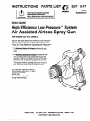
1
INSTRUCTIONS-PARTS
LIST
This manual contains important
Model AA2000
High Efficiency Low Pressure”
Air-Assisted
Part Number 222-615,
System
Airless Spray Gun
Series C
950 psi (66 bar) Maximum Working Fluid Pressure
100 psi (7 bar) Maximum Working Air Pressure *
10 psi (0.7 bar) Maximum Operating Air Pressure**
* The Maximum Workina Air Pressurq indicates the maximum air pressure the gun was designed to operate safely
under.
**The /&@num Operating Air Pressure indicates the maximum air pressure the air cap supplied with this gun was
designed to operate at or below to comply with California
Wood Rule 7736. To guarantee compliance to rule 1136,
the gun must be used with Air Regulator Part No. 110-776.
This regulator limits the operating pressure to 10 psi (0.7
bar), using an air supply pressure of 100 psi (7 bar).
U.S. Patent Nos. 3843,052; 4,386,739
United Kingdom Patent No. 2 111 406 B
Patented 1984 Canada
Brevete 1984
French Patent No. 82-21202
Foreign Patents Pending
GRACO INC. P.O.BOX 1441
MINNEAPOLIS, MN 55440-1441
OCOPYRIGHT 1988, GRACO INC.
Table of Contents
SafetyWarnings ...............................
3
Installation
Ventilate the Spray Booth .....................
Required Accessories ........................
Connect the Air Line .........................
Connect the Fluid Line .......................
Grounding ..................................
6
6
7
7
7
Operation
How Air-Assisted Airless Spray Gun Operates ... 7
Select A Spray Tip ...........................
8
Install a Spray Tip ............................
8
Adjust the Spray Pattern and Apply the Fluid .... 8
Flush the Gun Daily .........................
10
Clean the Spray Gun and System Daily ........
10
2 307-947
Troubleshooting ..............................
11
Service
Air Valve Service ............................
Fluid Packing Replacement ..................
12
12
Parts ........................................
14
Optional Parts ...............................
15
Accessories
.................................
16
Spray Tip Selection Charts ....................
18
Technical Data ...............................
19
Dimensions ..................................
19
Warranty ............................
Back Cover
WARNINGS
High Pressure Spray Can Cause Serious Injury. For Professional Use Only.
Observe All Warnings. Read and understand all instruction manuals before operating equipment.
FLUID INJECTION HAZARD
General Safety
This equipment generates very high fluid pressure.
Spray from the gun, leaks or ruptured components
can inject fluid through your skin and into your body
and cause extremely serious injury, including the
need for amputation. Also, fluid injected or splashed
into the eyes or on the skin can cause serious damage.
Never point the spray gun at anyone or at any part of
the body. Never put hand or fingers over the spray tip.
Never try to stop or deflect leaks with your hand or body.
Never try to “blow back” paint; this is not an air spray
gun.
Always follow the Pressure Relief Procedure, at
right, before cleaning or removing the spray tip or
servicing any system equipment.
Check operation of all equipment safety devices
before each use.
Medical Alert - Airless Spray Wounds
If any fluid appears to penetrate your skin, get emergency medical care at once. Do not treat as a simple cut. Tell the doctor exactly what fluid was injected.
NOTE TO PHYSICIAN: Injection into the skin is a
traumatic injury. It is important to treat the injury
surgically as soon as possible. Do not delay treatment to research toxicity. Toxicity is a concern with
some exotic coatings injected directly into the blood
stream. Consultation with a plastic surgeon or
reconstructive hand surgeon may be advisable.
Spray Gun Safety Devices
Be sure all gun safety devices are operating properly
before each use. Do not remove or modify any part of
the gun; this can cause a malfunction and result in
serious injury.
Safefy Latch
Whenever you stop spraying, even for a moment,
always set the gun safety latch in the closed or
“on safe” position, making the gun inoperative. See
Fig. 3, page 8. Failure to set the safety latch can result
in accidental triggering of the gun.
Diffuser
The gun diffuser breaks up spray and reduces the
risk of fluid injection when the tip is not installed.
Check diffuser operation regularly. Follow the Pressure Relief Procedure, below, then remove the spray
tip. Aim the gun into a grounded metal pail, holding
the gun firmly to the pail. Using the lowest possible
pressure, trigger the gun. If the fluid emitted is not
diffused into an irregular stream, replace the diffuser
immediately.
Spray Tip Safety
Use extreme caution when cleaning or changing
spray tips. If the spray tip clogs while spraying,
engage the gun safety latch immediately. Always follow the Pressure Relief Procedure, below, and then
remove the spray tip to clean it,
Never wipe off build-up around the spray tip or air cap
until pressure is fully relieved and the gun safety latch
is engaged.
Pressure Relief Procedure
To reduce the risk of serious injury, including fluid
injection, splashing in the eyes or on skin, or injury
from moving parts, always follow this procedure
whenever pump is shut off, when checking or servicing any part of system, when installing or changing
spray tips and whenever you stop spraying.
1. Engage the spray gun safety latch.
Shut off the power to the pump.
3. Close the bleed-type master air valve (required in
system).
4. Disengage the gun safety latch.
5. Hold a metal part of gun firmly to the side of a
grounded metal container and trigger the gun to
relieve fluid pressure.
6. Engage the gun safety latch again.
7. Open pump drain valve (required in system)to
help relieve fluid pressure in the displacement
pump. In addition, open the drain valve connected to the fluid pressure gauge (in a system
with fluid regulation) to help relieve fluid pressure
in the hose and gun. Triggering the gun to relieve
pressure may not be sufficient. Have a container
ready to catch the drainage.
8. Leave drain valve(s) open until you are ready to
spray again.
If you suspect that the spray tip or hose is completely
clogged or that pressure has not been fully relieved
after following the steps above, very slowly loosen the
hose end coupling and relieve pressure gradually,
then loosen completely. Now clear the tip or hose
obstruction.
2.
307-947
3
Static electricity is created by the flow of fluid through
the pump and hose. If every part of the equipment is
not properly grounded, sparking may occur, and the
system may become hazardous. Sparks can ignite
fumes from solvents and the fluid being sprayed, dust
particles and other flammable substances, whether
you are pumping indoors or outdoors, and cause a
fire or explosion, serious injury, and property damage.
Sparks may also occur when plugging in or unplugging a power supply cord. Do not plug in or unplug
any power supply cords in the spray area when there
is any chance of igniting fumes still in the air.
If you experience any static sparking or feel even a
slight shock while using this equipment, stop spray
ing immediately. Check for proper grounding of the
entire system. Do not use the system again until the
cause of the problem is identified and corrected.
Grounding
To reduce the risk of static sparking, ground the
pump and all other equipment used or located in the
spray area. Check your local electrical code for
detailed grounding instructions for your area and type
of equipment and be sure to ground all of the
following equipment:
1. Pump: use a ground wire and clamp as instructed
in your separate pump instruction manual.
2. Air, fluid, and hydraulic hoses connected to the
pump: use only grounded hoses with a maximum
of 500 feet (150 m) combined hose length to
ensure grounding continuity. Refer also to Hose
Grounding Continuity, below.
Air compressors
and hydraulic power supplies:
ground according to the manufacturer’s recommendations.
4. Spray gun: obtain grounding through connection
to a properly grounded fluid hose and pump.
5. Fluid suppfy container: according to local code.
6. Object being sprayed: according to local code.
7. All solvent pails used when flushing, according to
local code. Use only metal pails, which are conductive. Do not place the pail on a non-conductive surface, such as paper or cardboard, which
interrupts the grounding continuity.
8. To maintain grounding continuity when flushing or
relieving pressure, always hold a metal part of the
gun firmly to the side of a grounded metal pail,
then trigger the gun.
Flushing Safety
To reduce the risk of fluid injection injury, static sparking, or splashing, follow the Pressure Relief Procedure on page 3, and remove the spray tip before
flushing. Hold a metal part of the gun firmly to the
side of a grounded metal pail and use the lowest possible fluid pressure during flushing.
Ventilate the Spray Booth
To prevent hazardous concentrations of toxic and/or
flammable vapors, spray only in a properly ventilated
spray booth.
Never operate the spray gun unless the ventilating
fans are operating.
HOSE SAFETY
High pressure fluid in the hoses can be very dangerous. If the hose develops a leak, split or rupture due
to any kind of wear, damage or misuse, the high pressure spray emitted from it can cause a fluid injection
injury or other serious injury or property damage.
All fluid spray hoses must have a spring guard on
both ends! The spring guards help protect the hose
from kinks or bends at or close to the coupling which
can result in hose rupture.
Tighten all fluid connections securely before each
use. High pressure fluid can dislodge a loose coupling or allow high pressure spray to be emitted from
the coupling.
Never use a damaged hose. Before each use, check
the entire hose for cuts, leaks, abrasion, bulging
cover, or damage or movement of the hose couplings.
If any of these conditions exist, replace the hose
immediately. Do not try to recouple high pressure
hose or mend it with tape or any other device. A
repaired hose cannot contain the high pressure fluid.
4 307-947
Handle and route hoses carefully. Do not pull on
hoses to move equipment. Do not use fluids or solvents which are not compatible with the inner tube
and cover of the hose. Do not expose Grace hose to
temperatures above 180” F (82” C) or below -40”
F (-40” C).
Hose Grounding Continuity
Proper hose grounding continuity is essential to maintaining a grounded spray system. Check the electrical
resistance of your air and fluid hoses at least once a
week. If your hose does not have a tag on it which
specifies the maximum electrical resistance, contact
the hose supplier or manufacturer for the maximum
resistance limits. Use a resistance meter in the appropriate range for your hose to check the resistance. If
the resistance exceeds the recommended limits,
replace it immediately. An ungrounded or poorly
grounded hose can make your system hazardous.
Also read FIRE OR EXPLOSION HAZARD.
General Safety
Any misuse of the equipment or accessories, such as
overpressurizing, modifying parts, using incompatible
chemicals and fluids, or using worn or damaged
parts, can cause them to rupture and result in serious
injury, including fluid injection and splashing fluid in
the eyes or on the skin, or in fire, explosion or property damage.
System Pressure
The High Efficiency Low Pressure System 2500
AA2000 spray gun has a 950 psi (66 bar) Maximum
Fluid Working Pressure and 100 psi (7 bar) Maximum
Working Air Pressure (indicates the maximum air pressure the gun was designed to operate safely under).
Never exceed these pressures!
Never alter or modify any part of this equipment;
doing so could cause it to malfunction.
The Maximum Operating Air Pressure is 10 psi (0.7
bar). This indicates the maximum air pressure the air
cap supplied with this gun was designed to operate
at or below to comply with California Wood Rule 1136.
To guarantee compliance to rule 1136, the gun must
be used with Air Regulator Part No. 11O-776. This
regulator limits the operating pressure to 10 psi (0.7
bar), using an air supply pressure of 100 psi (7 bar).
Check the gun and all spray equipment regularly and
repair or replace worn or damaged parts immediately.
Read and follow the fluid and solvent manufacturer’s
literature regarding the use of protective eyewear,
gloves, clothing, respirator and other equipment.
Fluid Compatibility
Be sure all fluids and solvents used are chemically
compatible with the “Wetted Parts” shown in the
Technical Data on page 19. Always read the fluid
and solvent manufacturer’s literature before using
them in this gun.
Be sure that all spray equipment and accessories
added to the spray system are properly rated to withstand the maximum working pressure of your system.
Do not exceed maximum working pressure of any
component or accessory used in the system.
IMPORTANT
UnitedStatesGovernmentsafetystandardshavebeenadoptedunderthe OccupationalSafetyand HealthAct. Thesestandardsparticularlythe GeneralStandards,Part 1910,and the ConstructionStandards,Part 1926 - should be consulted.
307-947
5
Installation
KEY
A
B
C
D
E
F
Gun Air Inlet
Gun Fluid Inlet
Bleed-Type Master
Air Valve
Main Air Supply Line
Pump Air Regulator
Gun Air Regulator,
p/n 110-776, 10 psi
(0.7 bar)Maximum
Outlet Pressure
G Pump Ground Wire
H Air Line Filter
J Fluid Drain Valve
K Gun Air Hose
L Gun Fluid Hose
M Fluid Regulator Kit
N Fluid Filter
P Air Pressure
Relief Valve
Fig. 1
shown
in Fig.1 is only a guide
The typical installation
for selecting and installing air-assisted airless spray
systems. It is not an actual system design. Contact
your Grace representative for assistance in designing
a system to meet your needs.
The Grace fluid pump Model 217-523 is designed for
use in air-assisted airless systems. It has a maximum
working pressure of 950 psi (66 bar). See instruction
manual 307-595 for information on this pump.
Ventilate the Spray Booth
WARNING
To prevent hazardous concentrations of toxic and/
or flammable vapors, spray only in a properly ventilated spray booth.
Never operate the spray gun unless ventilation
fans are operating.
Check and follow all of the National, State and
Local codes regarding air exhaust velocity
requirements.
6 307-947
Required Accessories
WARNING
Two accessories, the bleed-type master air valve
(C), and the fluid drain valve (J) are required for
your system to reduce the risk of serious injury
from moving parts, splashing, or fluid injection
when shutting off the pump.
The bleed-type master air valve (located downstream of the pump air regulator) relieves air
trapped between the valve and the pump, after
the pump is shut off. Trapped air can cause the
pump to cycle unexpectedly
and result in serious
injury
if you
are adjusting
or repairing
the pump.
The fluid drain valve(s) helps relieve fluid pressure
in the displacement pump, hose and gun when
shutting off the pump. Triggering the gun to relieve
pressure may not be sufficient, especially if there
is a clog in the hose, gun, or tip.
Installation
Connect the Air Line
Install fluid drain valve(s) (J) to help relieve fluid
pressure.
Install an air line filter (H) to ensure a clean, dry air
supply to the gun. Dirt and moisture in the line can
ruin the appearance of your finished piece.
NOTE: The gun fluid connector (6) has a l/4-18
npsm (Rl/4- 19) compound male thread that is compatible with NPSM and BSP female connectors.
Install Air Pressure Regulator 1lo-776 (F) to control
the air pressure to the gun and limit it to 10 psi (0.7
bar) Maximum Operating Air Pressure.
Install a bleed-type master air valve (C) on the main
air line. Install a bleed-type master air valve or air
pressure relief valve (P), which is easily accessible
from the pump and downstream from the pump air
regulator (E).
Install an in-line fluid filter (see part no. 210-500 in
the Accessories section) on the gun fluid connector
(B) to avoid clogging the spray tip with particles from
your fluid.
NOTE: The gun air inlet has a l/4-1 8 npsm
@1/4-l 9) compound male thread that is compatible
with NPSM and BSP female swivel connectors.
Connect the grounded fluid hose (L) to the gun fluid
connector (B) or optional in-line filter.
Connect the air hose (K) from the air supply to the
gun air inlet.
Grounding
Connect the Fluid Line
WARNING
To reduce the risk of serious injury, be sure your
entire system is properly grounded. Read FIRE
AND EXPLOSION HAZARD on page 4. The gun
is grounded by connecting it to a properly
grounded pump and hose.
Install a fluid pressure regulator (M) to control fluid
pressure to the gun. Some applications require
fine-tuned control of fluid pressure. You can control
fluid pressure more accurately with a fluid pressure
regulator than by regulating the air pressure to the
w-v.
Operation
The spray gun has a built-in lead and lag operation.
When triggered, the gun begins emitting air before
the fluid is discharged. When the trigger is released,
the fluid stops before the air flow stops. This helps
assure the spray is atomized and prevents fluid
buildup on the air cap.
WARNING
The wallet sized warning card 179-960, provided
with the gun, should be available and easily
accessible at all times for anyone operating or
servicing this equipment. The card contains
important information on what to do if a fluid injection injury occurs. Additional cards are available at
no charge from Grace.
I
How the Air-Assisted Airless
Spray Gun Operates
The air-assisted airless gun combines airless and air
spraying concepts. The spray tip shapes the fluid into
a fan pattern, similar to a conventional airless spray
tip, but at a lower pressure. Air from the air cap further atomizes the fluid and completes the atomization
of the paint tails into the pattern. The pattern adjustment valve controls the width of the pattern.
1
Note that the air-assisted airless spray gun differs
from an air spray gun in that increasing the pattern air
reduces the pattern width. To increase the pattern
width, less pattern air or a larger size tip must be
used.
Remember, this is not an air spray gun; for your
safety be sure to read and follow the Warnings on
pages 3 to 5 and throughout the text of thus
307-947
7
Operation
Select a Spray Tip
Horizontal Spray Pattern
Vertical Spray Pattern
Use the Spray Tip Selection charts on page 18, as a
guide for selecting an appropriate spray tip for your
application. The fluid output and pattern width
depend on the size of the spray tip, the fluid viscosity,
and the fluid pressure.
NOTE: When spraying very low viscosity fluids, use
the optional fluid needle 220-413 (see page 15). The
standard needle may not provide positive shut off for
such fluids.
Install a Spray Tip
To reduce the risk of a fluid injection injury, Always
Pattern
ki~gtment
before removing or installing a spray tip.
Install a spray tip in the gun. The air cap and spray tip
position determines the direction of the spray pattern.
Safety Latch Disengaged
or in OFF SAFE Position
Rotate the air cap (the spray tip rotates with it) as
needed for the desired spray pattern direction. See
Fig. 2.
Adjust the Spray Pattern & Apply the Fluid
WARNING
To reduce the risk of serious injury, including fluid
injection, and splashing in the eyes or on the skin:
1. Never point the spray gun at anyone or any part
of the body or put your hand or fingers over the
spray tip when adjusting the spray pattern or
spraying fluid.
2. Always engage the trigger safety latch when you
stop spraying. See Fig. 3.
Safety Latch Engaged
or in ON SAFE Position
::$2
; ,: .,,.
......:::.:;ri:
:..I
..
,.:.,
3. Never exceed the maximum air and fluid working pressure of the lowest rated component in
your system. See System Pressure in the
EQUIPMENT MISUSE HAZARD Section on
page 5.
1. Set the fluid pressure at 300 psi (21 bar).
2. Trigger the gun to check the atomization: do not
be concerned about the pattern shape yet.
8 307-947
i
.....
No Air
Too Little Air
Right Amount
of Air
Operation
Adjust the Spray Pattern & Apply
the Fluid (Continued’
1. Increase the fluid pressure just to the point where
a further increase in fluid pressure does not significantly improve fluid atomization. Do not exceed
950 psi (66 bar) fluid pressure to the gun.
4. When applying the fluid, keep the gun a consistant distance, 8 to 10 inches (200 to 250 mm),
from the surface of the object being sprayed.
Always hold the gun at a right angle from the surface. Do not make an arc with the gun as it
causes an uneven coat of fluid. See Fig. 5.
2. Close the pattern adjustment valve by turning the
knob (see Fig. 3) counterclockwise all the way.
This sets the gun for its widest pattern
3. Set the atomizing air pressure at about 5 psi (0.35
bar). Check the spray pattern, then adjust the air
pressure until all the tails are completely atomized
and pulled into the spray pattern. See Fig. 4.
RIGHT
NOTE: Do not exceed 10 psi (0.7 bar) air pressure to
the gun. The air cap supplied with this gun was
designed to operate at or below 10 psi (0.7 bar) air
pressure to comply with California Wood Rule 1136.
For a narrower pattern, turn the pattern adjust-
ment valve knob clockwise. If the pattern is still
not narrow enough, increase the air pressure to
the gun slightly or use a different size tip.
NOTE: For some spray tips, when the line air pressure to the gun is increased to a certain level, the
spray pattern will become round. This is the smallest
pattern width. Further increases in air pressure will
force the pattern to turn from horizontal to vertical or
from vertical to horizontal.
WRONG
0793
307-947
9
Operation
Flush the Gun Daily
WARNING
Dressure Relief Procedure
Toreduce the risk of serious injury, including fluid
njection, splashing in the eyes or on skin, or injury
‘ram moving parts, always follow this procedure
Nhenever the pump is shut off, when checking or
servicing any part of the system, when installing or
:hanging spray tips and whenever you stop
spraying.
1. Engage the spray gun safety latch.
2. Shut off the power to the pump.
3. Close the bleed-type master air valve
(required in system).
4. Disengage the gun safety latch.
5. Hold a metal part of the gun firmly to the side
of a grounded metal waste container and trigger the gun to relieve fluid pressure.
6. Engage the gun safety latch again.
7. Open the pump drain valve (required in system) to help relieve fluid pressure in the displacement pump. In addition, open the drain
valve connected to the fluid pressure gauge
(in a system with fluid regulation) to help
relieve fluid pressure in the hose and gun.
Triggering the gun to relieve pressure may not
be sufficient. Have a container ready to catch
the drainage.
8. Leave the drain valve(s) open until you are
ready to spray again.
If you suspect that the spray tip or hose is completely clogged or that pressure has not been fully
relieved after following the steps above, very slowly loosen the hose end coupling and relieve pressure gradually, then loosen completely. Now clear
the tip or hose obstruction.
1. Follow the Pressure Relief Procedure Warning,
above.
2. Disconnect the atomizing air hose and the fluid
supply line.
5. Hold a metal part of the gun firmly against a
grounded metal waste container and trigger the
gun until all traces of paint are removed from the
gun passages. See Fig. 6.
6. Follow the Pressure Relief Procedure Warning
at left.
7. Disconnect the solvent supply.
Clean the Spray Gun & System Daily
CAUTION
Never immerse the gun in solvent. Doing so can
damage packings and allow solvent in the air passages, which can cause poor atomization and gun
Do not use metal tools to clean holes in the air
cap or spray tip. Metal instruments may damage
holes and distort the spray pattern.
1. Follow the Pressure Relief Procedure Warning
at left.
2. Clean the outside of the gun with a soft cloth
dampened with compatible solvent.
3. If using an in-line filter, remove and clean it thoroughly in a compatible solvent.
4. To avoid damaging the spray tip and air cap,
clean them with a compatible solvent and soft
brush. To clean the air cap passages, use a soft
brush or other soft tool, with an air blow gun.
5. Clean the system’s fluid filter and air line filter.
Ground
Wire
3. Remove the spray tip.
4. Connect the solvent supply to the gun.
When flushing or relieving
pressure, maintain firm
metal-to-metal contact
between the gun and a
grounded metal container
CAUTION
Be sure the solvent is compatible with the fluid
being sprayed to avoid clogging the gun’s fluid
passages.
10 307-947
Fig. 6
Troubleshooting
I
WARNING
To reduce the risk of serious injury, including fluid injection, splashing fluid or solvent in the eyes or on the
skin, or injury from moving parts, always follow the Pressure Relief Procedure Warning on page 10 whenever you shut off the pump, when checking or servicing any part of the spray system, when installing, cleaning or changing spray tips, and whenever you stop spraying.
NOTE: Check all possible remedies in the Troubleshooting Charts before disassembling the gun.
General Troubleshooting
I
Replace packings (47) or
I needle (5). See page 12.
Fluid leakage from back
of fluid needle
Worn packings or needle shaft.
Air leakage from front
of gun
Air valve (52) not seating properly.
Clean, service. See page 12.
Fluid leakage from front
of gun.
Needle worn or damaged.
Replace fluid needle (5).
See page 12.
Worn diffuser housing.
Replace diffuser housing (30).
See page 12.
Fluid tip seal leaking.
Tighten or replace tip (28).
Fluid inlet fitting leaking.
Replace gasket (33). The gasket (33)
must be replaced if the fluid fitting
(67) is removed.
Fluid in air passages from
air holes in cap.
Spray Pattern Troubleshooting
PROBLEM:
IMPROPER SPRAY
PATTERN
CAUSE
SOLUTION
Fluttering or spitting spray
Insufficient fluid supply.
Adjust fluid regulator or fill fluid
supply tank.
Air in paint supply line.
Check, tighten siphon hose
connections, bleed air from
paint line.
Fluid build-up or spray tip
partially plugged.
Clean spray tip. See page 10.
On defective side of pattern, air horn
holes are partially or totally plugged.
Clean air horn holes with solvent
and soft brush. See page 10.
Air horn holes partially or totally
plugged.
Clean air horn holes with solvent
and soft brush. See page 10.
Irregular pattern
Pattern pushed to one side,
same side of air cap gets
dirty.
NOTE: Some improper patterns are caused by the improper balance between air and fluid.
307-947
11
Service
WARNING
To reduce the risk of serious injury, including fluid
injection, and splashing in the eyes or on the skin,
or injury from moving parts or electric shock, always follow the Pressure Relief Procedure
Warning on page 10 before servicing any part of
the gun or system.
NOTE: Follow the Service Notes in Fig. 7 when reassembling the gun. Also refer to the parts drawing on
page 14 for parts not shown in Fig. 7.
Air Valve Service
1. Remove the trigger (3) and valve cap (11). See
Fig. 7.
Fluid Packing Replacement
1. If leakage occurs at the back of the fluid needle
(5), replace the needle packings (47) and inspect
the needle shaft. See Fig. 7.
2. Remove the air cap retainer (25), air cap (27),
fluid tip (28), and air separator (32).
3. Pull the trigger to back the fluid needle ball off the
seat. Unscrew the diffuser (30). Inspect the fluid
gasket (33) for any visible damage. Remove and
replace if necessary.
4. Remove the trigger (3).
5. Remove the hex nut (21) from the fluid needle (5)
while holding the square part of the fluid needle.
2. Unscrew the needle nut (49) while holding the
flats of the air valve (52) stem with a long nose
pliers.
6. Pull the fluid needle (5) and compression spring
(24) from the front of the gun.
ECAUTION
To prevent leakage, be careful not to scratch the
7. To remove the old packings, insert the packing
removal tool (55) into the front of the gun and
screw it into the packings (47). Pull the packings
from the front of the gun. Clean and inspect all
parts for wear or damage, replacing as needed.
3. Remove the spring (10) and air valve (52). See
Fig. 7.
8. Insert the new packings (47) onto the needle (5)
shaft as shown in Detail D of Fig. 7.
4. If there is air leakage at the air valve (52), unscrew
the packing nut (50) and carefully remove the
u-cup packing (51). Replace packing if worn or
damaged. When reinstalling, be sure the u-cup
faces inward.
9. Install the fluid needle (5) with the packings (47).
Be careful not to damage the packings.
5. If leakage occurs internally or the front of the gun
leaks air when untriggered, clean and inspect the
air valve and the spring for wear or damage.
Replace as needed.
6. For best air valve life, lubricate the external air
valve shaft (point A) with light oil after each day’s
use.
12 307-947
10. Screw the hex nut (21) to the bottom thread of the
needle. Torque it to 4 to 6 in-lb (5 to 8 N*m); do
not over tighten.
11. Install the trigger. Lubricate the diffuser threads.
Pull the fluid needle (5) back with the trigger while
screwing the diffuser (30) back into the gun.
Torque it to 23 to 27 ft-lb (37 to 32 Nom).
12. Reassemble the air separator (32)) fluid tip (28),
air cap (27), and air cap retainer (25).
Service
27
SERVICE NOTES:
A
Gasket (33) must be replaced if fluid connector (67 or l-see page 14) is removed or replaced.
Fluid leakage into air chambers may result if new gasket is not installed.
A
A
Lubricate threads
Apply anaerobic pipe sealant to threads
A
Apply high strength sealant to threads
A
Thread nut to bottom thread of needle
A
U-cup lips face inward
A
Torque to 23-27
ft-lb (31-37
Nom)
A
Torque to 20-24
ft-lb (27-32
Nom)
A
Torque to 15- 19 ft-lb (20-26
Nom)
Q
Torque to 4-6 in-lb (5-8 Nom)
An/
.
Fig. 7
307-947
13
18
26
28
\
A3
67
A
32
SERVICE NOTES (See Fig. 7 for additional Informatlon):
For Direct Hose Connection
(Paris shipped unassembled)
14 307-947
A
Gasket (33) must be replaced if fluid connector (67 or 1)
is removed or replaced. Fluid leakage into air chambers
may result if new gasket is not installed.
A
Lubricate threads
A
Torque to 23-27
ft-lb (31-37
Nom)
A
Torque to lo-14
ft-lb (14-19
Nom)
Use Only Genuine Grace Parts and Accessories.
Ref.
No.
Part No.
1
178-415
2
3
5*A
7
10*
11
18
19
20
21*
24*&
25
26*
27
28
Qty-
Description
CONNECTOR, fluid
(not assembled)
106-917 ADAPTER, air
178-454 TRIGGER, gun
217-488 NEEDLE, fluid
217-489 VALVE, pattern adjustment;
Includes items 62 & 63
106-903 SPRING, compression, air valve
178-408 CAF1valve, air
203-953 CAPSCREW, hex hd,
1O-24 x 0.375”
160-217 PIN, pivot
222-616 BODY, gun
177-528 NUT, hex
109-022 SPRING, compression, fluid
217-526 RETAINER, air cap
107-079 O-RING,PTFE
222-608 AIR CAP
182-XXX FLUID TIP; Customer’s choice;
See Chart on page 18 to order
1
1
1
1
1
1
1
1
1
1
1
1
1
1
1
1
Ref.
No.
30*
32
33*
Part No.
217-300
178-414
178-422
47*$1 218-042
49
50
51*
52*
55*
62*
178-767
178-765
105-452
217-487
178-798
168-110
63”
105-456
64A
66
67
179-960
218-566
180-547
*
Description
DIFFUSER-SEAT
SEPARATOR,air
GASKET, fluid, Delrin@
Qty*
1
1
3
(1 sent unassembled)
PACKING KIT, needle, Delrin &
UHMW polyethylene
NUT, needle, air
NUT, packing, air
U-CUP,PTFE
VALVE, air
TOOL, packing
O-RING, nitrile rubber;
Included with item 7
RETAINER, clip; Included with
item 7
WARNING CARD (not shown)
GUARD, trigger
CONNECTOR, fluid
1
These parts are included in Repair Kit 217-525.
A Replacement
cost.
Warning cards are available at no
A Optional replacement
below.
parts are available. See
Optional Parts
Must order separately.
Four Finger Trigger 183-l 04
Longer than standard trigger. Reduces trigger pull
when spraying mastics and heavy fluids. Replaces
item 3.
Plastic Ball Tipped Fluid Needle 220-413
For fluid pressures below 35 bar (500 psi) and light
viscosity fluid. Replaces item 5.
Ruby Ball Tipped Fluid Needle 222-497
For use with acid catalized finishes. Replaces item 5.
Fluid Needle Compression Spring 106-452
For spraying higher solids or heavier viscosity fluids.
Replaces item 24.
Ultra High Molecular Weight Polyethylene Needle
Packing Kit 221-150
Use to replace needle packings (item 47) when spraying urethane fluids. Helps eliminate isocyanate crystallization in packing area.
Ultra High Molecular Weight Polyethylene Diffuser
Seat 223-572
For use with very thin or acid-catalyzed fluids.
Fine Finish Tip Diffuser 223- 139
For use with Fine Finish Spray Tips. Not recommended for use with standard spray tips.
307-947
15
Accessories
Use Only Genuine Grace Parts and Accessories
Fluid Filters
3000 psi (207 bar) Maximum Working Pressure
214-570 with carbon steel bowl and support.
218-029 with aluminum bowl and support.
To convert Standard Fluid Pressure Regulator
206-661 to 1000 psi (70 bar) working pressure,
order the following parts:
501-511 Compression Spring
101-696 Fluid Pressure Gauge; 0- 1000 psi
(O-70 bar) regulated pressure range
Stainless Steel Screens
167- 024
167-025
167-026
167-027
595 micron (30 mesh)
250 micron (60 mesh)
149 micron (100 mesh)
74 micron (200 mesh)
In-line Fluid Filter 210-500
100 mesh. Fits onto the gun’s fluid connector.
l/4-18 npsm.
210-501
Bleed-type Master Air Valve
300 psi (21 bar) Maximum Working Pressure
Relieves air trapped in the air line between the pump
air inlet and this valve when closed.
107-141 3/4 npt(m xf)
107-142 l/2 npt(m x 9
Air Pressure Regulator 1lo-776
High Pressure Ball Valves
5000 psi (350 bar) Maximum Working Pressure
Install in outlets for individual fluid line control or install
in bottom of filter bowl as fluid drain valve.
210-657
210-658
210-659
214-037
Fluid Pressure Regulator 222-121
7500 psi (705 bar) Maximum fluid /n/et Pressure
150-1200 psi (10.5-84 bar) Regulated Pressure
Stainless Steel
l/2 npt(m), Vito@ seals
3/8 npt(m), Viton seals
3/8x l/4 npt(m), Viton seals
l/4 npt(m), PTFE eals
10 psi (0.7 bar) Maximum Working Pressure
Air Pressure Gauge 185-350
O-15 psi (0- 1 bar) Regulated Pressure Range
Air Line Filter
250 psi (17.5 bar) Maximum Working Pressure
106-148 318npt(f)
106-149 l/2 npt(f)
Nylon Static Free Fluid Hose
3000 psi (207 bar) Maximum Working Pressure
Part
ID
No.
214-700 3/16
Length
214-701
214-699
214-698
214-697
214-638
214-635
214-636
in (4.8 mm)
3/l 6 in 14.8 mm)
3/16 in i4.8 mmj
3/l 6 in (4.8 mm)
3116 in (4.8 mm)
l/4 in (6.4 mm)
l/4 in (6.4 mm)
l/4 in (6.4 mm)
2ft(610 mm)
3 fi (914 mm)
6ft(l.8m)
25 fl (7.6 m)
50 fl (15.2 m)
14 in (356 mm)
2ft(610 mm)
3 fl(914 mm)
214-629
210-540
210-541
l/4 in (6.4 mm)
i/4 in (6.4 mmj
l/4 in (6.4 mm)
15 fl (4.6 mm)
25ft (7.6 m)
50 ft (15.2 m)
Thread
Size
l/4 npsm(f)
l/4 npt(mxfI
l/4 npsmQ
l/4 npsm(f)
l/4 npsm(f)
l/4 npsm(9
1I4 npsm(f)
l/4 npsm(t) x
l/4 npt(m)
1I4 npsm(9
l/4 npsm(f)
l/4 npsm(f)
Corrosion-Resistant Fluid Hose 224-551
PTFE tube, SST cover, SST couplings
l/4 in. (6.4 mm) ID, 19 in. (483 mm) long, l/4 npsm(f)
16 307-947
Air Line Lubricator
250 psi (17.5 bar) Maximum Working Pressure
214-847 318npt(f)
214-848 l/2 npt(f)
Air Hose 185-353
200 psi (14 bar) Maximum Working Pressure
3/8 in. (9.5 mm) ID, 25 ft (7.6 m) long, coupled,
l/4 npsm
Accessories
Use Only Genuine Grace Parts and Accessories
Air Pressure Verification Kit 224-250
For use in checking air cap pressure at various gun
inlet pressures. Do not use the air cap for spraying.
Assemble the kit as shown in the drawing below.
Install the air cap on the gun. Turn on the air to the
gun, then actuate the gun and read the resulting air
cap pressure.
The air cap pressure reading will vary slightly,
depending on the position (rotation) of the air cap on
the gun, but with the inlet atomizing air pressure set
to a maximum of 10 psi (0.7 bar) by air regulator
110-776, the average air cap pressure will be 5.8 psi
(0.4 bar). Gauge accuracy is +I- 2% over the middle
half of the gauge scale, +/- 3% over the remainder of
the gauge scale.
1O:l Monark Pump 217-523
950 psi (66 bar) Maximum Working Pressure
Wall Bracket 206-220
Cart 208-210
Pump Suction Hose 214-960
Pail Suction Tube 165-787
Drum Suction Tube 206-266
Grounding Clamp And Wire 222-011
12 ga, 25 ft (7.6 m) wire
Brush 101-892
For cleaning gun.
Ref.
No.
1
2
Part No.
186-862
224-l 87
2a
2b
108-294
054-177
2c
2d
2e
11O-552
104-192
102-730
Description
QW
1
AIR CAP,tapped
GUAGE ASSEMBLY;
1
Includes items 2a-2e
1
CONNECTOR, tube
TUBE, bulk
10 in.
(order by length needed)
CONNECTOR, elbow; l/8 npt(m)
1
1
COUPLING, pipe, l/8 npt(f)
GAUGE, 0 to 15 psi (0 to 1 bar)
1
pressure range
l
l
l
l
l
307-947
17
Spray Tip Selection
STANDARD SPRAY TIPS
Orlflce
Size
Inches)
0.007
0.009
0.011
0.013
Inches
Fan Wldth
at 12”
(300 mm)
2-4(50-100)
4-6(1W-150)
S-8(150-200)
8-10(2W-250)
4-6(1W-150)
S-8(150-200)
6-10(200-250)
*Light to
Medlum
Vlscoslty
A oz/mln
(Ilters/mln)
*Heavy
vlscoslty
fl oz/mln
(Iiterslmln)
(04;
Orlflce
Size
Inches)
Part
No.
182-107
182-207
182-307
182-407
4-6(1W-150)
6-8(150-200)
S-10(200-250)
lo-12(250-300)
12-14(300-350)
10.0
(0.3)
4-6(100-150)
S-8(150-200)
8-10(200-250)
lo-12(250-300)
12-14(300-350)
13.0
(0.4)
*Light to
Medium
vlscoslty
11odmln
(Ilters/mln)
0.019
28.0
(0.6)
lo-12(250-300)
12-14(300-350)
14-16(350-400)
0.021
182-212
162-31:
182-412
182-512
182-61:
0.023
0.025
*Fluid output at 600 psi (41 bar).
35.0
(1.0)
8-10(200-250)
lo-12(250-300)
12-14(300-350)
14-16(350-400)
16-18(400-460)
I
I
10.0 (0.3)
I
I
50.0
(1.5)
lo-12(250-300)
12-14(3W-350)
14-16(350-400)
16-18(4W-460)
182-312
I
I
0.014 (0.356)
13.6 (0.4
6-8
(152-203)
102-314
0.012 (0.305)
10.0 (0.3)
10-12
(250-300)
182-512
0.014 (0.356)
13.6 (0.4
I
I
10-12
(250-300)
182-514
I
I
0.016 (0.406)
17.0 (0.5)
10-12
(250-300)
182-516
0.018 (0.457)
20.9 (0.6)
IO-12
(250-300)
182-516
0.020 (0.508)
I
25.8 (0.8)
*Fluid output at600 psi (41 bar).
18 307-947
part no. 223- 739.
6-8
(152-203)
I
10-12
(250-3001
I
182-520
182-421
182-521
182-621
182-721
182-621
182-423
182-523
182-623
182-723
162-823
For use in application of certain urethanes, clearcoats, and lightweight air-dry enamels. All these tips require replacement of
standard diffuser-seat with Diffuser-seat
27.0
(0.8)
lo-12(250-300)
12-14(3W-350)
14-16(350-400)
FINE FINISH SPRAY TIPS
0.012 (0.305)
Part
No.
8-10(2W-250)
lo-12(250-300)
182-211
182-311
182-411
182-511
182-611
I
*Heavy
vlscoslty
fl oz/mln
(Iiters/mln)
0.017
182-20s
182-30s
182-405
(:;
Inches
Fan Wldth
at 12”
(300 mm)
I
42.0
(1 .a
182-425
182-525
182-625
182-725
182-825
Technical Data
Dimensions
Maximum Working Fluid Pressure . . . 950 psi (66 bar)
*Maximum Working Air Pressure . . . . . . . 100 psi (7 bar)
**Maximum Operating Air Pressure . . . . . 10 psi (0.7 bar)
Weight (less filter) . . . . . . . . . . . . . . . . . . 1.2 lb (0.55 Kg)
Wetted Parts . . . . . . . Stainless Steel, Carbide, Ultra
Weight
Molecular
High
Polyethylene, PTFE Delrin@
PTFE and De/h@ are registered trademarks of the
DuPont co.
,9 In
5 mm)
*The MAX/MUM WORKlNG AIR PRESSURE indicates the
maximum air pressure the gun was designed to operate
safely under.
**The MAXIMUM OPERATING AIR PRESSURE indicates
the maximum air pressure the air cap supplied with this
gun was designed to operate at or below to comply with
California Wood Rule 7736. To guarantee compliance to
rule 1136, the gun must be used with Air Regulator Part
No. 11O-776. This regulator limits the operating pressure to 10 psi (0.7 bar), using an air supply pressure of
100 psi (7 bar).
Manual
Change Summary
114-18 npsm (M/4-19)
Compound Thread
This manual was revised to change the gun series
letter to C and to change air regulator 185-349 to
part no. 11O-776.
307-947
19
The Grace Warranty and Disclaimers
WARRANTY
Waco warrants all equipment manufactured by it and bearing its name to be free from defects in material and workmanship on the
date of sale by an authorized Grace distributor to the original purchaser for use. As purchaser’s sole remedy for breach of this warranty, Grace will, for a period of twelve months from the date of sale, repair or replace any part of the equipment proven defective.
This warranty applies only when the equipment is installed, operated and maintained in accordance with Grace’s wriien recommendations.
This warranty does not cover, and Grace shall not be liable for, any malfunction, damage or wear caused by faulty installation, misapplication, abrasion, corrosion, inadequate or improper maintenance, negligence, accident, tampering, or substitution of nonGrace component parts. Nor shall Grace be liable for malfunction, damage or wear caused by the incompatibility with Grace
equipment of structures, accessories, equipment or materials not supplied by Grace, or the improper design, manufacture, installation, operation or maintenance of structures, accessories, equipment or materials not supplied by Grace.
This warranty is conditioned upon the prepaid return of the equipment claimed to be defective to an authorized Grace distributor
for verification of the claim. If the claimed defect is verified, Grace will repair or replace free of charge any defective parts. The
equipment will be returned to the original purchaser transportation prepaid. If inspection of the equipment does not disclose any
defect in material or workmanship, repairs will be made at a reasonable charge, which charges may include the costs of parts,
labor and transportation,
DISCLAIMERS AND LIMITATIONS
The terms of this warranty constitute purchaser’s sole and exclusive remedy and are in lieu of any other warranties (express or
implied), including warranty of merchantability or warranty of fitness for a particular purpose, and of any non-contractual
liabilities, including product liabilities, based on negligence or strict liability. Every form of liability for direct, special or consequential
damages or loss is expressly excluded and denied. In no case shall Grace’s liability exceed the amount of the purchase price. Any
action for breach of warranty must be brought within two (2) years of the date of sale.
EQUIPMENT NOT COVERED BY GRACO WARRANTY
Grace makes no warranty, and disclaims all implied warranties of merchantablllty and fitness for a particular purpose, with
respect to accessories, equipment, materials, or components sold but not manufactured by Grace. These items sold, but not
manufactured by Grace (such as electric motor, switches, hose, etc.) are subject to the warranty, if any, of their manufacturer.
Grace will provide purchaser with reasonable assistance in making any claim for breach of these warranties.
Grace Phone Numbers
TO PLACE AN ORDER, contact your Grace distributar, or call Grace: l-800-328-0211
Toll Free
FOR Tf CHNlCAL ASSISTANCE, service repair information or answers about the application of Grace
equipment, call: l-800-543-0339
Toll Free
Sales Offlces: Atlanta, Chicago, Dallas, Detroit, Los Angeles, Mt. Arlington (N.J.)
Forelgn Offices: Canada; England; Korea; Switzerland; France; Germany; Hong Kong; Japan
GRACO INC.
20 307-947
P.O. BOX 1441
PRINTED IN U.S.A.
MINNEAPOLIS, MN
307-947 12/88 Revised lo/93
55440-1441