1
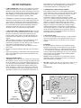
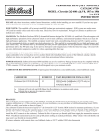
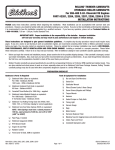
Performer RPM
Camshaft/Lifters/Lube Kit
CATALOG #7106
MODEL: 352-428 c.i.d. Ford V8
•
•
•
•
•
•
❑
❑
❑
❑
❑
PLEASE study these instructions carefully before installing your new camshaft. If you have any questions or problems, do not
hesitate to call our Technical Hotline at: 1-800-416-8628.
CAMSHAFT: Edelbrock Performer RPM camshafts are ground specifically for use with the corresponding Performer RPM
manifold. The Performer manifold #7105, and Performer RPM camshaft #7106, are designed to work as a team to give you better
driveability and performance. They are dyno-matched and street-proven. For best results, use the Edelbrock manifold/camshaft
package with the carburetor and headers we recommend. Performer RPM camshafts are designed for use with modified or high
performance cylinder heads and valve train components only. High performance adjustable rocker arms required.
NOTE: Maximum performance is achieved only when the Edelbrock Performer RPM Power Package components are use with the
following equipment:
Performer RPM manifold/camshaft/timing set/valve springs
• Performer Series carburetor #1407
Fuel delivery system of adequate capacity
• Aftermarket/re-curved distributors
• 2" headers
IMPORTANT: This instruction sheet provides general installation guidelines which can affect your warranty. Read it carefully. It is
not our intent to cover each detail of installation here; a step-by-step procedure manual would be far too lengthy. We want to caution
you that installing a camshaft is a complicated procedure that requires a good general knowledge of automotive engines. If you are
not confident that you can complete the camshaft installation successfully, we suggest you consider having it installed by an
experienced mechanic.
CAUTION: Improper installation will result in LOW MILEAGE, POOR PERFORMANCE, COSTLY RE-INSTALLATION, and
ENGINE DAMAGE. TO AVOID THESE PROBLEMS YOU MUST DO THE FOLLOWING: Carefully study and understand all
instructions. Examine the camshaft for possible shipping damage (if damaged contact you dealer immediately).
PREPARATION CHECKLIST
TOOLS AND EQUIPMENT—Use the following checklist for items needed.
Box and open-end wrenches
❑ Pliers (channel locks & hose clamp)
Screw drivers (regular and phillips)
❑ Torque wrench
Harmonic balancer puller
❑ Hammer
Socket set
❑ Gasket scraper or putty knife
Distributor wrench
❑ Gear puller-for crankshaft sprocket
• HARDWARE & PARTS TO BUY
❑ Intake gaskets–Fel-Pro Printoseal or
equivalent
❑ RTV silicone sealant
❑ Edelbrock Sure Seat Valve Springs #5706
•
1.
2.
3.
4.
5.
6.
7.
8.
❑
❑
❑
❑
❑
Pipe plugs, if needed
Edelbrock Gasgacinch, #9300
Chalk Paper and pencil
Radiator coolant
Edelbrock Performer-Link True Rolling
❑
❑
❑
❑
Timing light
Vacuum gauge
Water bucket
Rags
Timing Chain #7808
❑ Front cover oil seal-OEM or equivalent
INSTRUCTIONS FOR ENGINE PARTS REMOVAL BEFORE CAMSHAFT INSTALLATION
Disconnect battery.
9. Remove carburetor and intake manifold. Remove fuel pump.
For ease of installation, keep all parts in some sort of order.
CAUTION: If your engine has non-adjustable rocker arms
WARNING: Do not remove radiator cap or radiator hose if
you must check for proper lifter pre-load after installing new
engine is hot.
cam. If lifter pre-load is not correct, it will be necessary to
Drain radiator coolant, move fan shroud back and remove fan
install
and spacer from water pump. On air conditioned vehicles,
custom length pushrods or adjustable rocker arms.
remove bolt, lower idler pulley and compressor-to- water
10. Remove hydraulic valve lifters.
pump mount. Disconnect hoses and brackets. Most vehicles
11. Remove crankshaft pulley and, using a suitable puller,
will require radiator removal prior to cam removal. Remove
crankshaft dampener.
water pump.
12. Disconnect fuel pump outlet line from fuel pump; remove fuel
Disconnect all linkage from carburetor such as throttle, throttle
pump. Remove front cover bolts and cut oil pan gasket flush
springs, transmission, cruise control and automatic choke.
with cylinder block. Remove front cover and water pump as
Tag and remove vacuum lines.
an assembly.
Remove valve covers.
NOTE: The front cover oil seal should be replaced before the
Remove distributor cap and wires, rotate engine until rotor
front cover is re-installed.
points towards number 1 terminal in cap and pointer on front
13. Rotate engine until timing marks are aligned as shown in
cover is on Top Dead Center (TDC) and remove distributor.
Figure 1.
Note the approximate position of the vacuum advance canister
14. Remove cam sprocket bolt, washer, and fuel pump eccentric.
in relation to the manifold to assist in getting the distributor
Slide sprocket and timing chain forward to remove.
properly located during re-installation.
15. Remove thrust plate and camshaft. Using appropriate gear
Remove rocker arms and pushrods.
puller, remove crank sprocket.
page 1
#63-0021
Rev. 8/01
•
1.
2.
3.
•
1.
2.
•
1.
2.
VALVESPRINGS CAUTION:
WARNINGS ABOUT YOUR WARRANTY
In order for this Performer RPM cam and lifter kit to be
covered under ANY WARRANTY you MUST use the correct
Edelbrock Sure Seat Valve Springs. Failure to install new
Edelbrock valve springs with your new Performer RPM cam
could cause the cam lobes to wear excessively and could
cause additional engine damage.
This camshaft is designed to function with Edelbrock Sure
Seat valve springs #5706 (single with dampener). Do not use
dual valve springs with this camshaft.
Check and set spring height to factory specifications for your
year and model. If using Edelbrock #5706, set to 1.820".
NOTE: Due to the various settings through the years, we
advise checking Mitchell, Motors, Chilton, or Ford service
manuals for correct spring height setting for your vehicle.
For non-rotator engines, you may want to install Edelbrock
Valve Spring Retainer Kit #9720.
•
LIFTERS
New lifters must be used with new camshaft. Use only the
lifters supplied with this kit.
WARNING: Do not “pump-up” the lifters or pre-soak
them in oil. This will defeat the self-adjusting mechanism
of the lifter, and may result in bent or broken pushrods,
valves, etc. upon initial engine start-up. If lifter
pre-lubrication is desired, use an engine pre-lubing device
after engine assembly.
Check to be sure that all lifters fit freely in the lifter bores. It
may be necessary to use a brake wheel cylinder hone on lifter
bores to ensure proper fit.
5.
INSTALLATION INSTRUCTIONS
Coat cam lobes and bottoms of each lifter with MoS2 lube
(supplied) to prevent cam lobe and lifter wear from occurring
during initial start-up.
Install new camshaft with new sprockets, timing chain and
lifters.
NOTE: Drive pin in front of cam should be pressed into the
timing gear from the rear of the gear (camshaft side) until the
pin protrudes from the front of the gear by .060". This will
allow the pin to engage a drive hole in the one-piece fuel
pump eccentric. A replacement fuel pump eccentric can be
ordered from your Ford dealer if necessary - order part
number C3AZ-6287-A.
CAUTION: Use Edelbrock Performer RPM True-Rolling
Timing Chain and Gear Set #7808. Do not use late model
timing chain & gear sets that are designed in a retarded
position and are not recommended for this camshaft
installation. Edelbrock Timing Sets feature three keyways for
specific timing selection. Use "0" timing marks for most
applications. Use locking compound material on the bolt
threads holding timing gear to cam. Torque to factory
recommendations specified in motor repair manual (40-45
ft./lbs.). Install camshaft with timing marks lined up as
recommended by factory specifications. See Figure 1.
When using Performer RPM Timing Chain and Gear Sets
(7800 series) with Edelbrock cam and lifter kits, straight up
timing alignment is achieved. If any other timing gear set is
used, it is necessary to check cam position for correct timing
alignment. This requires indexing the camshaft with a degree
wheel to verify timing alignment. O.E.M. or non-Edelbrock
timing gear sets are not recommended for use with Edelbrock
camshafts.
•
1.
2.
3.
4.
6.
•
1.
2.
3.
4.
5.
6.
7.
•
1.
page 2
INSTALLING PUSHRODS AND ROCKER ARMS
After the cam is installed and timed correctly (see Figure 1), it
will be necessary to check each pushrod for correct lifter
pre-load.
VALVE ADJUSTMENT
Install intake manifold using new intake gasket set and torque
manifold bolts to 25 ft./lbs.
Turn the engine over until the No. 1 cylinder exhaust lifter
starts to move up. At this point install pushrod and intake
rocker arm, rocker shaft, and rocker shaft bolts. Adjust to zero
clearance between rocker arm and valve tip. Continue
tightening the adjusting nut one-half (1/2) turn.
Turn the engine over again until the intake lifter just stops
coming down. At this point install pushrod and adjusting nut
on exhaust rocker arm and repeat the same procedure as
above.
The above procedure assures correct hydraulic lifter pre-load.
Repeat this procedure for each of the other seven
cylinders.Torque rocker shaft bolts to 40-45 ft./lbs.
Re-install front cover, fuel pump, water pump, and oil pan
using new gaskets.
Install crankshaft dampener and torque to factory
specification.
INSTALLING DISTRIBUTOR AND TIMING ENGINE
NOTE: Before installing your distributor, check the gear drive
on the distributor and oil pump for any signs of wear. If worn,
be sure to replace with new or you may wear out your
camshaft prematurely. This is especially true when rebuilding
your engine and a high performance oil system is used, which
generates a heavier load on the camshaft gear system.
Edelbrock camshafts are designed to use OEM-type gears and
oil pumps only.
Turn the engine over in the direction of rotation until the No.
1 intake valve closes and continue until the pointer on the
front cover is approximately 5 degrees BTDC.
Re-install the distributor with the rotor pointing towards No. 1
terminal in the cap, and with the vacuum advance canister in
its original position.
Lightly tighten the hold-down clamp so that the distributor
can still be turned to determine final setting using a timing
light with the engine running.
Replace valve covers, carburetor linkage and remaining
vacuum and electrical connections.
Re-install air conditioner, if so equipped.
Re-install radiator, fan shroud, and belts (if removed), fill
radiator with coolant and re-connect battery.
Double check all connections, fuel lines, etc. before starting
engine.
CAMSHAFT/LIFTER RUN-IN
CAUTION: Change the engine oil and filter before start-up
and again after break-in. Do not allow the engine to run
under 2000 rpm for the first 1/2 hour. Vary engine speed
between 2000 and 2500 rpm. Slow idle speeds will result in
severe cam and lifter wear.
Start the engine and bring to break-in rpm.
IMPORTANT INSTRUCTIONS
AFFECTING YOUR WARRANTY
•
CAM LOBE WEAR- Cam lobe wear is almost non-existent
unless mismatched parts are used or installation of the cam
and lifters is done improperly. Most cam damage is caused by
the timing gear coming loose due to improper torque on bolt.
Bolts holding gear to camshaft should be torqued carefully
and a locking compound applied to threads of bolts.
•
CAUTION: Use Edelbrock Performer RPM Timing Chain
and Gear Set #7808. Do not use late model timing chain and
gear sets that are designed for emission-controlled engines.
These timing sets are machined in a retarded position and are
not recommended for this camshaft installation. Edelbrock
Timing Sets feature three keyways for specific timing
selection. Use the "0" position for most applications.
•
CAM GEARS AND CAMSHAFT END PLAY- If cam gear
becomes loose, the cam will slide back in the block, causing
the lifters to hit the lobes next to them and also the cam
bearing journals. If the engine is run after this happens, the
bottom of the lifters and the sides of the lobes will become
clipped.
When installing a camshaft, it is always important to check
for proper operating clearances, especially when high
performance components are used. Things to look for that can
cause failure and damaged parts are as follows:
Improper valve-to-piston clearance (this should be no less
than 0.080").
Rocker arm stud slot clearance (both ends; valve closed and
open).
Proper spring settings (see dimensions with spring instruction
sheet; correct dimensions mean maximum performance and
longer engine life).
1.
2.
3.
•
SPECIAL INSTRUCTION
CAUTION: Some models of early vehicles use a short pin in
the camshaft. For these vehicles, we suggest grinding the long
pin in the Edelbrock cam to the same length as the short pin,
or remove the stock pin and install it with the Edelbrock cam.
With the Edelbrock manifold and camshaft package plus a
header installation, a carburetor jet change may be required
for best performance. Due to the varied applications of year
and model of vehicles, no one combination could suffice for
all installations. The following procedure is only a guideline
and in many cases, the manufacturing specifications for
recommended carburetors or timing may be best.
•
CARBURETION AND IGNITION TIMING
Best carburetor results were with the Edelbrock Performer
Series carburetors #1407 (750 cfm with manual choke). Stock
jetting can be used for most installations, however, various
conditions may require re-calibration for optimum
performance (changes in altitude, temperature, exhaust
system, etc.). Ignition timing for this package may vary with
each application. A good starting figure would be between 12
degrees to 14 degrees initial timing at idle with vacuum
advance disconnected. Total advance should not exceed 34
degrees to 38 degrees with initial and centrifugal weights
combined and should be at full advance at 3000-3500 rpm.
After timing is adjusted, re-connect the vacuum advance line.
NOTE: The best combination for any particular vehicle or
application must be determined by trial and error using the
above information as a guideline.
•
VACUUM ADVANCE
For best cruise and light throttle response, a vacuum advance
curve was used with 16° to 20° maximum advance at 14-16
inches of vacuum and 4° to 10° advance at 10-12 inches of
vacuum.
•
HEADERS
For best performance, headers are recommended with the
Performer rpm package. For this application, they should be
2" diameter, approximately 31" long and terminating into a
3-1/2" collector. The remainder of the exhaust system should
consist of dual exhaust and tail pipes, at least 2-1/2" diameter
with low back-pressure mufflers such as Edelbrock RPM
Series stainless steel mufflers.
NOTE: The best combination for any particular vehicle or
application must be determined by trial and error using the
above information as a guideline.
•
PLEASE complete and mail your warranty card. Be sure to
write the model number of this product in the “Part #____”
space.
THANK YOU.
1
2
6
5
7 8
5
4
2 4
3
Timing
Marks
3
1
6
7
Figure 2
Firing Order 1-5-4-2-6-3-7-8
352-428 c.i.d. Ford V8
Turn distributor clockwise to advance timing.
Figure 1
Timing Chain
Sprocket Alignment
page 3
8
CAMSHAFT: Performer RPM Hydraulic
CATALOG #7106
ENGINE: Ford 352-428 c.i.d. V8
(1963-1/2 and later)
RPM RANGE: 1500-6500
CAUTION: Do not use dual valve springs.Use only recommended Edelbrock Sure Seat Valve Springs #5767. Use stock
ratio rocker arms only (1.76:1).
CAMSHAFT: Performer RPM Hydraulic
CATALOG #7106
ENGINE: Ford 352-428 c.i.d. V8
(1963-1/2 and later)
RPM RANGE: 1500-6500
CAUTION: Do not use dual valve springs.Use only recommended Edelbrock Sure Seat Valve Springs #5767. Use stock
ratio rocker arms only (1.76:1).
Duration at .006" Lift:
Duration at .050" Lift:
Intake 296°
Intake 236°
Exhaust 296°
Exhaust 236°
Duration at .006" Lift:
Duration at .050" Lift:
Intake 296°
Intake 236°
Exhaust 296°
Exhaust 236°
Lift at cam:
Lift at valve:
Intake .325"
Intake .572"
Exhaust .325"
Exhaust .572"
Lift at cam:
Lift at valve:
Intake .325"
Intake .572"
Exhaust .325"
Exhaust .572"
Timing at .050 Lift:
Open
Intake
15° BTDC
Exhaust
51° BBDC
Centerlines:
•
Close
41° ABDC
5° ATDC
Lobe Separation:
Intake Centerline:
108°
103°
CAUTION: Use Edelbrock Performer RPM Timing Chain
and Gear Set #7808. Do not use late model timing chain and
gear sets that are designed for emission-controlled engines.
These timing sets are machined in a retarded position and
are not recommended for this camshaft installation.
Edelbrock Timing Sets feature three keyways for specified
timing selection. Use “0” position for most applications.
CAMSHAFT: Performer RPM Hydraulic
CATALOG #7106
ENGINE: Ford 352-428 c.i.d. V8
(1963-1/2 and later)
RPM RANGE: 1500-6500
CAUTION: Do not use dual valve springs.Use only recommended Edelbrock Sure Seat Valve Springs #5767. Use stock
ratio rocker arms only (1.76:1).
CAMSHAFT: Performer RPM Hydraulic
CATALOG #7106
ENGINE: Ford 352-428 c.i.d. V8
(1963-1/2 and later)
RPM RANGE: 1500-6500
CAUTION: Do not use dual valve springs.Use only recommended Edelbrock Sure Seat Valve Springs #5767. Use stock
ratio rocker arms only (1.76:1).
Duration at .006" Lift:
Duration at .050" Lift:
Intake 296°
Intake 236°
Exhaust 296°
Exhaust 236°
Duration at .006" Lift:
Duration at .050" Lift:
Intake 296°
Intake 236°
Exhaust 296°
Exhaust 236°
Lift at cam:
Lift at valve:
Intake .325"
Intake .572"
Exhaust .325"
Exhaust .572"
Lift at cam:
Lift at valve:
Intake .325"
Intake .572"
Exhaust .325"
Exhaust .572"
Timing at .050 Lift:
Open
Intake
15° BTDC
Exhaust
51° BBDC
Centerlines:
•
Lobe Separation:
Intake Centerline:
Close
41° ABDC
5° ATDC
108°
103°
CAUTION: Use Edelbrock Performer RPM Timing Chain
and Gear Set #7808. Do not use late model timing chain and
gear sets that are designed for emission-controlled engines.
These timing sets are machined in a retarded position and
are not recommended for this camshaft installation.
Edelbrock Timing Sets feature three keyways for specified
timing selection. Use “0” position for most applications.