1
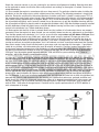
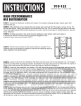
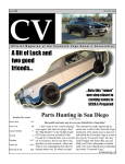
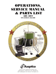
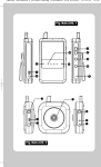
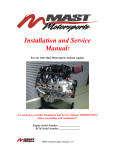
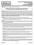
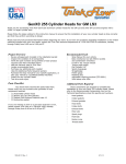
INSTRUCTIONS
915-11CAM
©Speedway Motors, Inc Dec. 2008.
PLEASE READ INSTRUCTIONS COMPLETELY BEFORE
STARTING YOUR INSTALLATION
IMPORTANT NOTE: Recent changes in todayʼs oil products and internal engine design, as well as other
factors, have lead to an increase of premature camshaft failures. The hardness of the lifter base or the taper of
the cam lobe are often suspect, however, in almost every case it has been determined that the failure is
unrelated to the camshaft manufacture or quality.
The three things with the greatest influence on camshaft durability are:
PROPER CAMSHAFT INSTALLATION, SET-UP, AND BREAK IN PROCEDURES
This instruction sheet will provide the necessary steps that, when followed accurately, will assure a durable and
long lasting camshaft installation. Some of the topics may not apply to every application, but all of the
information will be beneficial during the camshaft installation process. If you do not understand these
instructions or have questions, do not hesitate to contact our tech department for assistance. Failures within the
first hour of operation are almost always the result of improper installation procedures
ADEQUATE LUBRICATION
Another major factor in the increase of flat tappet camshaft failures could be your favorite brand of engine oil.
Due to ever tightening federal environmental regulations, the EPA has mandated a reduction of some of the EP
(extreme pressure) additives in traditional motor oils, such as zinc (ZDDP) and manganese. Many race oils “for
off-road use only” and over-the-counter diesel oils such as Shell Rotella T, still contain those additives. Look for
oils meeting CI-4 or CI-4 Plus certification requirements. Failures that occur after the first hour of operation, but
before the next scheduled oil change, are normally due to the lack of EP lubricants in the oil that is being used.
Synthetic oils are not recommended for use during the break in period to the first scheduled oil change.
INTERNAL ENGINE MODIFICATIONS OR COMPONENTS
Any new camshaft installation must use new lifters. Even “near new” lifters which have been operated on a
different cam lobe for even a few minutes can destroy the cam lobe of the new cam. Valve springs must be
properly matched to the camshaft. Valve springs that coil bind due to the increased lift of a new cam will
damage the cam lobes and / or bend pushrods. Springs with excessive seat pressure will destroy a cam lobe
on initial startup. If your springs exceed 125 lbs of seat pressure, or if you are running dual springs, you must
remove the inner spring or damper or replace with a lighter spring (approximately 100 lbs of seat pressure) for
the initial break in period. Failure to use new lifters and the proper valve springs will void any
consideration of warranty! High ratio rocker arms should also be avoided during the initial break in period.
Ratios higher than 1.5:1 increase the load at the cam/lifter interface (much like a stiff valve spring), which leads
to premature wear. We recommend the use of stock rocker arm ratios for break in. You may also choose to use
low ratio rocker arms, such as our 1.3:1 ratio rockers for break-in. Another current trend in performance engine
building is the use of thinner oils and tighter clearances of the crankshaft bearings and connecting rod side
clearance. When you add lifter galley oil restrictors, crankshaft scrapers, and windage trays you greatly reduce
the amount of oil being whipped around inside the crankcase. The cam lobe / lifter interface is lubed only by
the oil splashing off of the rotating crank assembly during operation. Reducing this oil splash can have an
adverse effect on the durability of the camshaft. Street cars with near stock oiling systems should be OK;
however, track cars with modified oiling systems may find it beneficial to use special lifters with a pressure
oiling hole in the contact face of the lifter. We carry these premium lifters for Chevy (p/n 282-80016) and small
block Ford (p/n 282-81716), and recommend that they be used in all applications with high valve spring rates or
aggressive profiles on flat tappet mechanical cams. Use of these lifters does not circumvent the necessity to
use reduced valve spring pressures and / or reduced rocker arm ratios for the initial break in period.
CAMSHAFT INSTALLATION
1. Prepare a clean work area and assemble the tools needed for the camshaft installation. These
instructions are generalized due to the wide variety of current production engines, and are not intended to
cover all aspects of every camshaft installation. We suggest that you use the appropriate automotive shop
manual for your engine/vehicle to help determine which items must be removed from the engine in order to
gain access to the camshaft, lifters, timing chain, rocker arms, and valve springs.
2. Disassemble engine as required. Once the timing chain is exposed, rotate crankshaft to line up the timing
marks. This will position engine at Top Dead Center of the #1 cylinder. Remove the cam sprocket, timing
chain, and cam retainer plate, if so equipped. Temporarily reinstall the cam sprocket to act as a handle and
remove all lifters. Carefully roll and slide cam out of engine, using caution not to nick or damage the cam
bearings.
3. Now is the time to inspect all of the old camshaft and valvetrain related components. The first factor to
consider is the general condition of the engine. As a new performance camshaft can increase power by up to
20% and expand the rev limit by 2000 rpm, it stands to reason that the engine must be in top notch
mechanical shape. As the cam will have more lift and a faster opening rate, excessive wear in the valve
guides, or a wear step in the valve stem can cause immediate, catastrophic damage such as bent pushrods,
broken rocker arms, and damaged camshaft lobes. Check the pushrods, rocker arms, and rocker studs for
excessive wear or damage. If the engine has accumulated several thousand street miles the distributor drive
gear must be closely inspected for wear, as a worn gear will quickly destroy the gear on the camshaft.
Likewise, the timing chain and gears must be replaced as a stretched timing chain will cause cam timing
variations and subsequent ignition timing fluxuation.
NOTE: If you are installing a replacement OEM style timing chain and gear set it is highly recommended
that you properly degree the new camshaft. Many OEM timing sets retarded camshaft timing for emission
compliance which greatly detracts from the performance potential of your new camshaft. Most aftermarket
performance timing sets maintain proper camshaft phasing, so it isnʼt absolutely necessary to degree the
cam in order for the engine to run efficiently. However, to assure maximum performance we recommend that
you degree your camshaft to verify that it is phased per manufacturers recommendations. To properly degree
the cam, refer to the instructions provided by the degree wheel manufacturer.
NOTE: A variety of special tools are required for the following steps. Consult your shop manual for specifics,
or contact the Speedway Tech Department for assistance. The number one factor in premature camshaft
failure is due to the use of incorrect valve springs. The following step is very important to the life of your new
camshaft, follow it closely. Many OEM valve springs do not have sufficient travel to accommodate the
increased lift of your new performance cam. If they are not replaced with the recommended valve springs
and retainers, immediate engine damage will result.
4. Remove the valve springs from the #1 cylinder, in accordance with
the procedures outlined in your service manual (this will involve
rotating the engine by hand to TDC of the #1 cylinder, inserting a
compressed air fitting into the spark plug hole, and using an on-theengine valve spring compressor, such as our p/n 910-81130, to
remove the springs). Whenever the valve springs are removed, stretch
a rubber band across the exposed stems of the two valves (or rocker
studs) to keep them from dropping into the cylinder when the air
source is disconnected. Using a valve spring height mic, such as our
p/n 910-81125, measure the installed height of your existing valve
springs, compare this dimension to those listed in the spring
requirements of your cam card. If you do not have a valve spring
1
height mic, you can use a 6” machinist rule. Install a pair of lightweight
valve height checking springs, like our p/n 910-81129, and temporarily
reinstall the valve spring retainer and keepers. Using the machinist
rule, measure spring height from the spring seat of the cylinder head to the lower edge of the retainer. (see
figure 1)
NOTE: Many smog era heads were factory equipped with exhaust valve rotators. These rotators require
shorter valvesprings and add additional weight to the valve train. If your engine is equipped with exhaust
valve rotators, you should replace all of your retainers with those recommended for the new valve springs
that you will be using.
Alternately, you can temporarily install the intake valve retainer on the exhaust valve for checking purposes
only.
2
A
RETAINER
TO GUIDE
CLEARANCE
B
RETAINER
TO OIL SEAL
CLEARANCE
After disconnecting compressed air source, with checking springs installed,
slowly rotate the crankshaft approximately 90 degrees to move the piston
away from TDC. Using hand pressure, push down on the valve stem until
the under side of the retainer bottoms out on the top of either the valve
guide or the valve seal. (see figure 2) Using your machinist rule, again
measure between the spring seat in the head and the retainer. Subtract this
dimension from the spring installed height dimension; the resultant
difference must be greater than the valve lift listed on your cam card.
Check both valves.
EXAMPLE:
Measured valve spring installed height
1.750”
Measured height @ interference to retainer - 1.200”
Total obtainable valve travel =
.550”
Safety margin for thermal expansion .060”
Available valve travel =
.490”
In this example, if the max lift of your cam is .485”, you have the necessary clearance to run this cam without
issue. If, however, you would install 1.6:1 ratio rocker arms instead of the stock 1.5:1 rockers, it would
increase the total lift to .517, and be dangerously close to binding the valvetrain and causing engine damage.
Next, check the available travel of
your
valve springs to assure that they
3
do
not
coil bind with the increased
C
cam lift. Place a valve spring into a
vise or arbor press and compress until
INSTALLED
coil bind occurs. Measure with your
COIL
A
HEIGHT
BIND
machinist rule or calipers. Subtract
B
HEIGHT
this dimension from the installed
height of the valve spring, using the
.060 safety margin as listed above, to
calculate the total spring travel available. (see figure 3) Again, if your valve lift exceeds the available spring
travel you must install new valve springs. The last thing to check on your valve springs is the seat pressure.
Take them to your local machine shop or use a valve spring pressure tester like our p/n 913-81103.
Compress the spring to the measured valve spring installed height dimension and check the pressure
reading. If your valve springs pass all of the above listed requirements, they may be reused. If they fail on
any one of the test criteria, they must be replaced with the recommended valve spring set. Leave the
checking springs installed on the #1 cylinder, you will use them again to check piston to valve clearance in a
later step.
5. Remove timing gear from crankshaft (a puller is normally required). Clean and inspect the cam bearings
and each lifter bore for scoring, nicks or other damage. Wrap a strip of scotchbrite around a long screwdriver
and clean any varnish from each lifter bore. On fresh engine builds, the lifter bores should be honed to the
proper .0015 - .002” clearance. Drain engine oil. Clean all debris and traces of gasket from the lifter valley
and timing cover area. Flush with mineral spirits or brake cleaner, use compressed air to blow dry. When all
fluid has drained from the oil pan, pour a bottle of clean SAE 30 wt. engine oil into the lifter valley from front
to back, when clean oil runs from the drain plug, reinstall plug. Pour a bottle of break-in oil additive with zinc
ZDDP, such as our p/n 282-159, over the lifter valley, and then continue to service oil in this fashion to the
full mark on the dipstick.
NOTE: The lubricants recommended in these instructions are not interchangeable. Each compound is
formulated to perform a specific function. Moly disulfide paste can plug small oil passages, break in lube
does not have the anti-galling properties of moly, assembly fluid does not have zinc for durability like break-in
lube. Use each recommended lube in its specified location and application only.
6. Remove the new cam and lifters from the package. Make sure that it is the proper part for your
application. Inspect all lobes, bearing surfaces and the distributor drive gear for damage that may have
occurred in shipping. It is a good idea to lightly burnish the drive gear with a wire brush to remove any sharp
edges, then wash the camshaft thoroughly with mineral spirits or brake cleaner and blow dry. Temporarily
install the camshaft timing gear to act as a handle. Use one of the new lifters, coated lightly with engine oil,
and check the fitment in each lifter bore of the block. Make sure that lifter fits freely in the bore with no
sticking or binding. Hydraulic lifters do not need to be “pumped up” prior to installation.
7. Install the crank gear of your new timing set onto the crank snout, using the proper tool. Rotate the
crankshaft back to TDC of the #1 cylinder. Apply a moly disulfide paste lube, such as our p/n 450-R4, to each
lobe of the cam, including the fuel pump eccentric (if applicable) and distributor drive gear. It is important to
coat the lobes completely, yet not excessively. Do not get moly paste on the camshaft bearing journals. Coat
the rear bearing journal of the camshaft with assembly lube, such as our p/n 915-4040. Carefully slide the
camshaft into the engine, lubing each bearing journal as it slides into the block. Take your time, be careful
not to scar the cam, cam bearings, or wipe the lube off of the cam lobes. Once seated, turn the cam until the
timing mark lines up properly with the crank gear. Remove temporarily installed cam gear. Install camshaft
retaining plate, (if so equipped) and torque bolts to factory specs. Install the new cam gear or sprocket and
timing chain. If installing an aftermarket timing set that includes thrust washers or bearings follow the
installation instructions of the timing set manufacturer. Make certain that the timing marks are properly
aligned and that the cam sprocket is seated properly on the camshaft. Torque bolts
to proper spec per your service manual. We recommend using locktite or a cam
bolt locking plate to positively retain the bolts.
8. Install lifters into the #1 cylinder positions. Lube only the sides of the lifter body
with assembly fluid, coat the bottom of each lifter with moly paste. Assemble the
pushrods and rocker arms, do not tighten rocker arm nuts at this time. Turn the
engine in the normal direction of rotation until the #1 exhaust rocker begins to
move. This assures that the intake lobe is on the base circle of the cam lobe (see
figure 4). Adjust the intake rocker arm nut to zero lash by spinning the intake
pushrod with your fingers as you tighten the adjuster nut. When you feel a slight
resistance in rotating the pushrod, you are at zero lash. Continue to rotate the
engine in the normal direction of rotation until the intake valve is full open, and then
starts to close. When it is nearly closed, stop and adjust the exhaust rocker arm to
zero lash.
Correct Position
of the cam lobe
and lifter for
setting preload.
Incorrect
4
9. Continue to rotate engine until the exhaust valve opens, and then begins to
close. Stop at approximately 20 degrees before TDC of the overlap cycle. Using your machinist rule (or a dial
indicator) check the height of the valve spring retainer. Push down on the rocker arm until the valve contacts
the piston. Note the reading. Compare the two readings, and write the number down. This is your valve to
piston clearance. Rotate the engine to 15 degrees before TDC, again take a measurement, compress until
contact with piston and take another measurement. Compare and note readings. Continue this process
stopping every 5 degrees from 20 degrees before TDC to 20 degrees after TDC. Repeat for the intake valve.
Minimum required piston to valve clearance is .100” on the intake valves and .120” on the exhaust valves.
When all checks are complete, remove rocker arms, pushrods, and lifters.
10. Now is the time to install the appropriate valve springs for the initial break in. If your original valve springs
have sufficient travel for the camshaft being installed (see step #4), but have a lower seat pressure than the
recommended springs, they can be re-installed for the initial 1-hour break in period. The lower valve spring
pressure will help the cam and lifters seat and establish a good wear pattern during the critical first 10
minutes of operation. If your original valve springs do not have adequate travel for the lift of the new cam,
they must be replaced. If the seat pressure of your new valve springs is higher than 100 lbs, remove the
inner spring or damper for the initial break-in run. Using the tools and procedures as outlined in step #4,
install the appropriate valve springs on all valves (note: now is a good time to install new valve stem seals).
11. With all of the valve springs installed, lube and install the lifters, pushrods, and rockers for the #1 cylinder
as described in step #8 to achieve zero lash. Apply a dab of moly lube to each end of the pushrod and the tip
of the valve stem. Apply assembly fluid to the rocker arm fulcrum. For hydraulic lifter cams, turn adjuster an
additional ½ turn from zero lash to properly preload the lifter plunger. On engines with non-adjustable valve
trains consult the shop manual for proper shimming procedures or select a custom length pushrod that
provides the recommended .020-.040 lifter preload.
On solid lifter cams, turn adjuster as required to obtain the valve lash listed on your cam card. Nonadjustable valve trains must be converted to an adjustable configuration when installing mechanical (solid
lifter) cams. Follow the same procedure to install the lifters, pushrods, and rocker arms on the remaining
cylinders. Double check everything.
12. Initial lubrication is extremely important as the cam lobes can be wiped out in the first 10 minutes if the
engine experiences a “dry start.” Prior to installing the ignition distributor it is highly recommended that you
pre lube the engine by using a primer shaft and electric drill. This assures that the oil filter, cam galley, and
lifters will have oil pressure immediately upon fire up. Using a marking compound such as white out, place a
dot on each pushrod. Crank the engine over with the starter 3 or 4 revolutions as you are priming the oil
system.
Watch the valvetrain closely as you are cranking for any obvious misalignment or binding. Note the white dots
on the pushrods to make sure that the lifters and pushrods are rotating as the engine is cranked. Correct any
noted deficiencies.
13. Re-assemble the engine in accordance with your shop manual. Pay particular attention when installing the
distributor so that the engine starts quickly, without excessive cranking. The following procedure is simple and
effective. Rotate the crankshaft in the normal direction of rotation until the #1 cylinder is coming up on TDC of
the compression stroke (both valves closed). Align the timing mark on the crank balancer at the recommended
initial timing setting (approximately 10 degrees before TDC). Install the distributor, making sure that it engages
the oil pump drive properly and is correctly seated (it may be necessary to pull the distributor housing and turn
the oil pump drive slightly by hand in order to engage the distributor shaft). With the distributor properly installed
and the hold-down clamp left slightly loose, rotate the distributor housing until the rotor is aligned with the #1
contact in the distributor cap. Tighten hold-down clamp.
14. Make certain that the fuel system is primed. Make sure that radiator is full and coolant hoses are properly
connected. Once the engine has been started, you can not idle it down to make any adjustments or corrections.
Turn the idle speed screw clockwise ½ to 1 turn to assure that the engine does not idle below 1500 rpm. Start
engine and bring to break-in rpm (2000 rpm), adjust idle speed screw as required. Change rpm every few
minutes to direct oil splash to different places inside the crankcase. Maintain engine rpm within the range of
1500 to 2500 rpm for the first 30 minutes of operation. If you note a strange noise, or a leak, or the engine is
starting to overheat, do not idle engine down, shut it off and note run time. Investigate and correct the situation,
then restart engine, bring it back into the break-in rpm range, and start counting run time again. If possible to
safely do so, perform a test drive during the next 30 minutes of break-in. Placing a load on the engine helps
insure proper operating temperatures and distribution of lubricant. Adjust idle speed down to 1500 rpm before
test drive, put transmission selector in neutral if sitting at a stop light, do not allow engine to lug down below
1500 rpm. Vary the engine speed frequently between 1500 and 2500 as you are driving. After 1 hour of
operation, adjust idle speed to recommended setting.
15. After the 1 hour break-in period, change the oil and filter. Add another bottle of oil additive. It is imperative
that you change the filter, as the moly particles and assembly contaminants will clog the filter element. Remove
the valve covers and inspect the valvetrain closely for any loose or damaged components. If you were using
break-in valve springs or have removed the inner spring from your valve springs, you can now replace them
with the proper springs, using the tools and procedures found in step #4. All valve springs must be installed at
the manufacturers recommended installed height. You may need a selection of different thickness valve spring
shims, or offset retainers or valve keepers in order to obtain the specified dimension (see figure 5). If you do not
need to replace the valve springs, perform a valve adjustment as outlined in step #8. During the adjustment
process, pay special attention to note any major differences in valve lash or preload from before the break-in
run. For example, if you have installed a mechanical cam and adjusted the valve lash to .020 at installation, but
measure one valve at .060 clearance after the break-in run, remove that rocker arm, pushrod, and lifter and
check closely for any bent or damaged components. When all is deemed acceptable install valve covers and
the job is complete. The oil and filter should be changed again at 1000 miles of operation, then resume the
normal 2500 – 3000 mile oil change interval. Continue to use a quality performance oil or ZDDP additive at
each subsequent oil change.
5
Standard
Installed Height
Taller
Installed Height
Shorter
Installed Height
IMPORTANT
DISCLAIMER In an effort to offer our customers the low prices, quick service and great value, Speedway Motors
reserves the right to change suppliers, specifications, colors, prices, materials. Each of the previous items is subject
to change without notice. Speedway is not responsible for any typographical errors or misinterpretations. Quantities
are limited on some items.
WARRANTY DISCLAIMER The purchaser understands and recognizes that racing parts, specialized street rod
equipment, and all parts and services sold by Speedway Motors, Inc. are exposed to many and varied conditions due
to the manner in which they are installed and used. Speedway Motors, Inc. makes no warranties, either express or
implied, including any warranty of merchantability or fitness for a particular purpose other than those contained in its
current catalog with respect to the goods identified on the face of the invoice. There is no warranty expressed or
implied as to whether the goods sold hereby will protect purchaser or ultimate user of such goods from injury or
death. Speedway Motors assumes no liability after this period.
DAMAGE CLAIMS Always inspect your package upon delivery. Inspect all packages in the presence of the delivery
driver. The driver must note any damage. Ask the driver the Carrier’s procedures for handling damage claims. You
must hold the original box, packing material and damaged merchandise for inspection or the carrier will not honor
the claim. Notify Speedway Motors customer service department for instructions on returning damaged goods.
Speedway is not responsible if no notification is given within 5 days of receipt.
SHORTAGES Always check the contents of your delivery to insure all the parts that you ordered were received. Please
read the invoice. Double check all packing materials, small items may be wrapped inside with these products.
Shortages may occur from damage to the box, so save all packing materials. Inspect the box for holes that would
allow parts to fall out. If you are missing any item(s) be sure to check your invoice for back orders or canceled items
before calling the customer service department. If Speedway has to split a shipment into multiple boxes, packages
may be delivered on different days. You need to contact the customer service department within 5 days of delivery
to assure the prompt replacement. Speedway Motors assumes no liability after this period.
REFUSALS All refused COD customers will be billed a 15% restocking charge plus freight to and from the
destination! If you have questions please contact Speedway’s customer service department.
WARRANTY CLAIMS If an item has a manufacturer’s warranty as being free from defects we will exchange only. If
the item has been used and you are requesting warranty work, this may take up to 30 days as warranty work is done
by the manufacturer NOT Speedway Motors. If you have any questions please contact customer service.
RETURNS Speedway wants you to be satisfied with your purchase. If within 30 days after you receive your shipment
you are not satisfied, you may return the item for refund or exchange. All exchanged or returned merchandise must
be in original factory condition with no modifications or alterations. Returned merchandise must include all packaging
materials, warranty cards, manuals, and accessories. If the items being returned need to be repackaged there will be
a re-packing charge. Re-pack the item in a sturdy box and include a copy of your invoice and complete the form on
the back of the invoice. You must ship orders back PRE-PAID. WE DO NOT ACCEPT COD SHIPMENTS. All exchanges
need to have reshipping charges included. Items that are returned after 30 days are subject to 15% restocking
charges. All fiberglass returned will have 15% restocking charge. No returns on electrical parts, video tapes, and
books. Absolutely no returns on special order or close out merchandise.
FREE CATALOGS Speedway Motors offers FREE catalogs for Race, Street, Sprint and Midget, Sport Compact and
Pedal Car restoration.
**Some items are not legal for sale or use in California on pollution controlled motor vehicles. These items are
legal in California for racing vehicles only which may never be used upon a highway.
Speedway Motors Inc., P.O. Box 81906
Lincoln, NE 68501 (402) 323-3200
www.speedwaymotors.com
©Speedway Motors, Inc. 2006