1
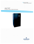
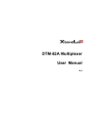
Precision Cooling
For Business-Critical Continuity™
Liebert® XDH™
User Manual - 50 & 60Hz
GENERAL SAFETY GUIDELINES
! WARNING
Risk of top-heavy unit falling over. Can cause death or injury.
Improper handling can cause equipment damage, injury, or death. Read all of the following
instructions before attempting to move, lift, remove packaging from the unit, or preparing
unit for installation.
! WARNING
Risk of explosive discharge. Can cause death or injury.
This unit contains fluids and/or gases under high pressure. Relieve system pressure before
cutting into or disconnecting piping or piping components.
! WARNING
Risk of high-speed moving parts. Can cause death or injury.
Disconnect all local and remote electric power supplies before working in the unit.
! WARNING
Risk of electric shock. Can cause death or injury.
Disconnect both power cords from the electrical supply outlets or from the receptacles on the
back of the unit before working within.
! CAUTION
Risk of overhead interference. Can damage unit or structure.
The unit may be too tall to fit through a doorway while on the skid. Measure the unit and
doorway heights and refer to the installation plans before moving the unit to verify
clearances.
! CAUTION
Risk of sharp edges, splinters and exposed fasteners. Can cause personal injury.
Only properly trained personnel wearing appropriate safety headgear, gloves, shoes and
glasses should attempt to move, lift, remove packaging from, or prepare unit for installation.
! CAUTION
Risk of improper operation and overpressurization. Can result in injury or property damage.
Only qualified personnel trained in HVAC installation or service should install or service this
equipment.
Read all installation, operating and safety instructions before proceeding.
Fluorinated Greenhouse Gas Requirements—European Union
Stationary air conditioning, refrigeration, heat pump equipments and stationary fire protection systems in the European Community market and operating with fluorinated greenhouse gases (f-gas),
such as R407C, R134a, R410A, must comply with the F-Gas Regulation: (EC) No. 842/2006 (F-gas).
The regulation prohibits, among other actions, venting fluorinated greenhouse gases to the atmosphere.
The F-Gas Regulation also requires operators to use use all measures that are technically feasible
and do not entail disproportionate cost to prevent leakage of these gases, to test for leakage regularly
and to recover f-gas during equipment service and maintenance and before disposing of equipment.
Refer to the full regulation for additional details.
TABLE OF CONTENTS
GENERAL SAFETY GUIDELINES . . . . . . . . . . . . . . . . . . . . . . . . . . . . . . . . . . . INSIDE FRONT COVER
1.0
LIEBERT XDH COMPONENT LOCATIONS AND MODEL NUMBER NOMENCLATURE . . . . . . . . .1
2.0
INTRODUCTION . . . . . . . . . . . . . . . . . . . . . . . . . . . . . . . . . . . . . . . . . . . . . . . . . . . . . . . . . .2
2.1
Product Description . . . . . . . . . . . . . . . . . . . . . . . . . . . . . . . . . . . . . . . . . . . . . . . . . . . . . . . . . . 2
2.2
References . . . . . . . . . . . . . . . . . . . . . . . . . . . . . . . . . . . . . . . . . . . . . . . . . . . . . . . . . . . . . . . . . . 2
2.3
Pre-Installation Checks . . . . . . . . . . . . . . . . . . . . . . . . . . . . . . . . . . . . . . . . . . . . . . . . . . . . . . . 2
2.4
Parts Included With the Liebert XDH . . . . . . . . . . . . . . . . . . . . . . . . . . . . . . . . . . . . . . . . . . . 2
2.5
Installation Considerations . . . . . . . . . . . . . . . . . . . . . . . . . . . . . . . . . . . . . . . . . . . . . . . . . . . . 3
2.5.1
Room Preparation. . . . . . . . . . . . . . . . . . . . . . . . . . . . . . . . . . . . . . . . . . . . . . . . . . . . . . . . . . . . . 3
3.0
GENERAL PRODUCT INFORMATION . . . . . . . . . . . . . . . . . . . . . . . . . . . . . . . . . . . . . . . . . . .4
3.1
Product/System Description . . . . . . . . . . . . . . . . . . . . . . . . . . . . . . . . . . . . . . . . . . . . . . . . . . . 4
3.2
Checking and Unpacking . . . . . . . . . . . . . . . . . . . . . . . . . . . . . . . . . . . . . . . . . . . . . . . . . . . . . . 4
3.3
Equipment Inspection . . . . . . . . . . . . . . . . . . . . . . . . . . . . . . . . . . . . . . . . . . . . . . . . . . . . . . . . 5
3.3.1
3.3.2
3.3.3
3.3.4
Recyclable Packaging . . . . . . . . . . . . . . . . . . . . . . . . . . . . . . . . . . . . . . . . . . . . . . . . . . . . . . . . . .
Unit Handling. . . . . . . . . . . . . . . . . . . . . . . . . . . . . . . . . . . . . . . . . . . . . . . . . . . . . . . . . . . . . . . .
Unpacking the Unit . . . . . . . . . . . . . . . . . . . . . . . . . . . . . . . . . . . . . . . . . . . . . . . . . . . . . . . . . . .
Taking the Unit off the Pallet . . . . . . . . . . . . . . . . . . . . . . . . . . . . . . . . . . . . . . . . . . . . . . . . . . .
5
6
6
7
4.0
MECHANICAL CONSIDERATIONS . . . . . . . . . . . . . . . . . . . . . . . . . . . . . . . . . . . . . . . . . . . . .9
4.1
Determining Placement in the Conditioned Space. . . . . . . . . . . . . . . . . . . . . . . . . . . . . . . . . . 9
4.2
Installing the Liebert XDH Within the Enclosure Row . . . . . . . . . . . . . . . . . . . . . . . . . . . . . . 9
4.2.1
Airflow Direction . . . . . . . . . . . . . . . . . . . . . . . . . . . . . . . . . . . . . . . . . . . . . . . . . . . . . . . . . . . . 10
5.0
PIPING . . . . . . . . . . . . . . . . . . . . . . . . . . . . . . . . . . . . . . . . . . . . . . . . . . . . . . . . . . . . . . .12
5.1
European Union Fluorinated Greenhouse Gas Requirements . . . . . . . . . . . . . . . . . . . . . . . 12
5.2
System Connection Configuration . . . . . . . . . . . . . . . . . . . . . . . . . . . . . . . . . . . . . . . . . . . . . . 12
5.3
Connection Methods and Points . . . . . . . . . . . . . . . . . . . . . . . . . . . . . . . . . . . . . . . . . . . . . . . 15
5.4
Piping Considerations—Hard-Piped Connections . . . . . . . . . . . . . . . . . . . . . . . . . . . . . . . . . 16
5.4.1
5.4.2
Venting the Holding Charge and Connecting to Mains . . . . . . . . . . . . . . . . . . . . . . . . . . . . . . 16
Brazing Preparations . . . . . . . . . . . . . . . . . . . . . . . . . . . . . . . . . . . . . . . . . . . . . . . . . . . . . . . . . 17
5.5
Connection Methods for Hard Pipe . . . . . . . . . . . . . . . . . . . . . . . . . . . . . . . . . . . . . . . . . . . . . 17
5.6
Recommended Piping Size . . . . . . . . . . . . . . . . . . . . . . . . . . . . . . . . . . . . . . . . . . . . . . . . . . . . 17
5.6.1
Connecting Methods—One-Shot Connections . . . . . . . . . . . . . . . . . . . . . . . . . . . . . . . . . . . . . 17
5.7
Field Installation of Liebert XD Flex Pipe Kit on the Liebert XDH . . . . . . . . . . . . . . . . . . . 18
5.8
Connecting Liebert XD Flex Pipes to Liebert XDH Modules. . . . . . . . . . . . . . . . . . . . . . . . . 19
5.9
Connecting a Liebert XDH with Liebert XD Flex Pipe to an Operational Liebert
XD System . . . . . . . . . . . . . . . . . . . . . . . . . . . . . . . . . . . . . . . . . . . . . . . . . . . . . . . . . . . . . . . . 19
5.10
Disconnecting a Liebert XDH With Liebert XD Flex Pipe From a Liebert XD System . . . . 21
5.11
Insulation . . . . . . . . . . . . . . . . . . . . . . . . . . . . . . . . . . . . . . . . . . . . . . . . . . . . . . . . . . . . . . . . . 22
6.0
ELECTRICAL . . . . . . . . . . . . . . . . . . . . . . . . . . . . . . . . . . . . . . . . . . . . . . . . . . . . . . . . . . . 23
6.1
Connecting High Voltage Wiring. . . . . . . . . . . . . . . . . . . . . . . . . . . . . . . . . . . . . . . . . . . . . . . 23
6.2
Connecting Low Voltage Wiring—Optional . . . . . . . . . . . . . . . . . . . . . . . . . . . . . . . . . . . . . . 24
5.8.1
Header System . . . . . . . . . . . . . . . . . . . . . . . . . . . . . . . . . . . . . . . . . . . . . . . . . . . . . . . . . . . . . . 19
i
7.0
INSTALLATION CHECKLIST AND SYSTEM FILL FOR STARTUP . . . . . . . . . . . . . . . . . . . . . . . 25
7.1
Checklist for Proper Installation . . . . . . . . . . . . . . . . . . . . . . . . . . . . . . . . . . . . . . . . . . . . . . . 25
7.2
Charging with Refrigerant and Starting the Liebert XD System . . . . . . . . . . . . . . . . . . . . . 25
8.0
OPERATION . . . . . . . . . . . . . . . . . . . . . . . . . . . . . . . . . . . . . . . . . . . . . . . . . . . . . . . . . . .26
8.1
Start the Liebert XDH . . . . . . . . . . . . . . . . . . . . . . . . . . . . . . . . . . . . . . . . . . . . . . . . . . . . . . . 26
9.0
MAINTENANCE . . . . . . . . . . . . . . . . . . . . . . . . . . . . . . . . . . . . . . . . . . . . . . . . . . . . . . . . . 27
9.1
Internal Access . . . . . . . . . . . . . . . . . . . . . . . . . . . . . . . . . . . . . . . . . . . . . . . . . . . . . . . . . . . . . 27
9.2
Fluorinated Greenhouse Gas Requirements. . . . . . . . . . . . . . . . . . . . . . . . . . . . . . . . . . . . . . 27
9.3
Remove Fan Tray . . . . . . . . . . . . . . . . . . . . . . . . . . . . . . . . . . . . . . . . . . . . . . . . . . . . . . . . . . . 28
10.0
SPECIFICATIONS . . . . . . . . . . . . . . . . . . . . . . . . . . . . . . . . . . . . . . . . . . . . . . . . . . . . . . . .29
FIGURES
Figure 1
Figure 2
Figure 3
Figure 4
Figure 5
Figure 6
Figure 7
Figure 8
Figure 9
Figure 10
Figure 11
Figure 12
Figure 13
Figure 14
Figure 15
Figure 16
Figure 17
Figure 18
Figure 19
Figure 20
Figure 21
Figure 22
Figure 23
Figure 24
Figure 25
Figure 26
Figure 27
Liebert XDH component locations . . . . . . . . . . . . . . . . . . . . . . . . . . . . . . . . . . . . . . . . . . . . . . . . . . . 1
Liebert XDH model number nomenclature . . . . . . . . . . . . . . . . . . . . . . . . . . . . . . . . . . . . . . . . . . . . 1
Liebert XDH hydraulic schematic . . . . . . . . . . . . . . . . . . . . . . . . . . . . . . . . . . . . . . . . . . . . . . . . . . . 4
Recommended unit handling equipment . . . . . . . . . . . . . . . . . . . . . . . . . . . . . . . . . . . . . . . . . . . . . . 5
Removing shipping package . . . . . . . . . . . . . . . . . . . . . . . . . . . . . . . . . . . . . . . . . . . . . . . . . . . . . . . . 6
Prepare ramp to remove the Liebert XDH from shipping pallet . . . . . . . . . . . . . . . . . . . . . . . . . . . 7
Attaching ramp, removing the Liebert XDH from pallet . . . . . . . . . . . . . . . . . . . . . . . . . . . . . . . . . 8
Liebert XDH dimensions . . . . . . . . . . . . . . . . . . . . . . . . . . . . . . . . . . . . . . . . . . . . . . . . . . . . . . . . . . 9
Liebert XDH placement in enclosure row . . . . . . . . . . . . . . . . . . . . . . . . . . . . . . . . . . . . . . . . . . . . 10
Change airflow direction. . . . . . . . . . . . . . . . . . . . . . . . . . . . . . . . . . . . . . . . . . . . . . . . . . . . . . . . . . 11
Typical Liebert XDH piping—interlaced connections. . . . . . . . . . . . . . . . . . . . . . . . . . . . . . . . . . . 12
Typical Liebert XDH piping—non-interlaced connection . . . . . . . . . . . . . . . . . . . . . . . . . . . . . . . . 13
Direct system configuration—hydraulic system schematic . . . . . . . . . . . . . . . . . . . . . . . . . . . . . . 13
Indirect system configuration—hydraulic system schematic. . . . . . . . . . . . . . . . . . . . . . . . . . . . . 14
Hard pipe connection diagram . . . . . . . . . . . . . . . . . . . . . . . . . . . . . . . . . . . . . . . . . . . . . . . . . . . . . 15
Supply and return—hard-piping connections . . . . . . . . . . . . . . . . . . . . . . . . . . . . . . . . . . . . . . . . . 16
Piping location and connecting sizes for pre-charged units . . . . . . . . . . . . . . . . . . . . . . . . . . . . . . 18
Liebert XD Flex Pipe dimensions—straight and 90-degree connections . . . . . . . . . . . . . . . . . . . . 18
Liebert XD prefabricated piping assembly . . . . . . . . . . . . . . . . . . . . . . . . . . . . . . . . . . . . . . . . . . . 20
Detail view of Liebert XD Flex Pipe and prefabricated piping port. . . . . . . . . . . . . . . . . . . . . . . . 20
Liebert XD system with prefabricated piping assembly and Liebert XD Flex Pipe . . . . . . . . . . 21
Profile view of the Liebert XD system . . . . . . . . . . . . . . . . . . . . . . . . . . . . . . . . . . . . . . . . . . . . . . . 22
Piping mains without Liebert XDH and Liebert XD Flex Pipe . . . . . . . . . . . . . . . . . . . . . . . . . . . 22
Liebert XDH electrical connections . . . . . . . . . . . . . . . . . . . . . . . . . . . . . . . . . . . . . . . . . . . . . . . . . 23
Condensate wiring entry points . . . . . . . . . . . . . . . . . . . . . . . . . . . . . . . . . . . . . . . . . . . . . . . . . . . . 24
Fan switches . . . . . . . . . . . . . . . . . . . . . . . . . . . . . . . . . . . . . . . . . . . . . . . . . . . . . . . . . . . . . . . . . . . 26
Remove fan tray . . . . . . . . . . . . . . . . . . . . . . . . . . . . . . . . . . . . . . . . . . . . . . . . . . . . . . . . . . . . . . . . 28
TABLES
Table 1
Table 2
Table 3
Table 4
Application limits . . . . . . . . . . . . . . . . . . . . . . . . . . . . . . . . . . . . . . . . . . . . . . . . . . . . . . . . . . . . . . . . 3
Branch piping sizes for pumped refrigerant loop . . . . . . . . . . . . . . . . . . . . . . . . . . . . . . . . . . . . . . 17
Liebert XDH specifications. . . . . . . . . . . . . . . . . . . . . . . . . . . . . . . . . . . . . . . . . . . . . . . . . . . . . . . . 29
Liebert XD Flex Pipe assemblies, supply and return . . . . . . . . . . . . . . . . . . . . . . . . . . . . . . . . . . . 30
ii
Liebert XDH Component Locations and Model Number Nomenclature
1.0
LIEBERT XDH COMPONENT LOCATIONS AND MODEL NUMBER NOMENCLATURE
Figure 1
Liebert XDH component locations
FRONT
(Top View)
Air
Return
Vents
Controls
Return Piping
Connection Bottom Circuit
Return Piping
Connection Top Circuit
Cooling
Air Supply
Vents
REAR
FRONT
Supply Piping
Connection Bottom Circuit
Supply Piping
Connection Bottom Circuit
Upper
Refrigeration
Circuit
FRONT
(Bottom View)
FRONT
Condensate
Detection
Connections
Lower
Refrigeration
Circuit
Condensate Pan
and Detection
Option (also in
bottom circuit)
Casters
(one at each
corner)
REAR
Adjustable Foot
(one at each corner)
Electrical
Connections
Figure 2
Stabilizers (one
at each corner)
Liebert XDH model number nomenclature
Example: XDH32BK— —0
XD
H
Liebert
X-Treme heat
density system
32
20 = Model size
32 = Model size
Horizontal row cooler
B
K
K = 120V-1ph-60Hz
S = 208-240-1ph-60Hz
220-240-1ph-50Hz
B = Base unit
D = Condensate detection
1
—
—
0
— = Domestic packaging
E = Export packaging
Revision level
— = Hard piped
P = Pre-charged (one-shot) Coupling
R = Removable Coupling
Introduction
2.0
INTRODUCTION
2.1
Product Description
The Liebert XDH cooling module is designed to be placed within a row of server enclosures in a hotaisle-cold-aisle arrangement. The Liebert XDH, available in a half-rack-width unit, is intended for
use with a Liebert XD pumped refrigerant cooling system, supplied by either a Liebert XDP or Liebert
XDC.
Warmer air from the enclosures is drawn in through the rear of the Liebert XDH, cooled and blown
into the cold aisle in a diffuse pattern. The cooling air is then drawn into the enclosures to cool the
equipment.
The Liebert XDH has dual refrigeration circuits, one in the upper half of the unit and the other in the
lower half. This permits increasing and decreasing cooling levels in response to server room conditions. The dual refrigeration circuits permits interlaced connection of two Liebert XD refrigerant
sources to enhance system reliability.
Controls on the front of the Liebert XDH permit independent operation of the two banks of fans. Dual
power connections ensure continued fan operation if one of two electrical sources fails.
The Liebert XDH is intended for use in low-humidity environments and does not need a drain connection. A condensate pan under each refrigeration unit collects the small amount of moisture expected
in the server room. An optional, factory-installed condensate detection system is available. The Liebert XDH is available with uni-directional or bi-directional air diffusers.
2.2
References
This document must be used together with site specific documentation and documentation for other
parts of the system.
2.3
Pre-Installation Checks
• Verify that the Liebert XDH voltage matches the available utility power. The serial tag with this
information is accessible by opening the Liebert XDH’s rear door. The tag is on a shelf near the
Liebert XDH’s midline.
• Check the received materials to be sure all required assemblies and parts have been received. If
you discover any external damage, report it to the shipping company and your local Liebert representative.
2.4
Parts Included With the Liebert XDH
•
•
•
•
•
•
User manual (this document)
Liebert XDH module
Power cords
Shipping/floor mounting brackets
Tie-down bracket assembly
Diffusers (top and bottom)
2
Introduction
2.5
Installation Considerations
The Liebert XDH is designed for placement within a row of computer cabinets in the data center in a
hot-aisle-cold-aisle arrangement. The Liebert XDH is 12" (305mm) wide, so it takes up little space.
For installation arrangement, see 4.2 - Installing the Liebert XDH Within the Enclosure Row.
Be sure to follow all applicable codes.
Determine whether the Liebert XDH includes the condensate detection option (factory-installed).
This option will require separate low voltage connections to a monitoring unit. A front panel alarm
and indicator alert the user to condensation inside the unit. To minimize the possibility of condensation, insulate all piping between the Liebert XDH and the Liebert XDP or Liebert XDC.
If the Liebert XDH is installed at the end of a row, Liebert recommends using uni-directional air diffusers to direct cooling air into the cold aisle, toward the equipment racks. If the Liebert XDH is
installed between racks within a row, Liebert recommends using bi-directional air diffusers, directing
the cooling air toward the equipment racks on either side of the Liebert XDH.
Table 1
Application limits
Input Voltage
2.5.1
Range of Return Air Conditions to Unit
Minimum
Maximum
Dry Bulb Temperature
Relative Humidity
-10%
+10%
60° to 100°F (16° to 38°C)
20% to 80%
Room Preparation
The room should be well-insulated and must have a sealed vapor barrier. The vapor barrier in the
ceiling and walls can be a polyethylene film. Paint on concrete walls and floors should contain either
rubber or plastic.
NOTE
The vapor barrier is the single most important requirement for maintaining environmental
control in the conditioned space.
Outside or fresh air should be kept to a minimum when temperature and humidity must be tightly
controlled. Outside air adds to the cooling, heating, dehumidifying and humidifying loads of the site.
Doors should be properly sealed to minimize leaks and should not contain ventilation grilles.
3
General product information
3.0
GENERAL PRODUCT INFORMATION
3.1
Product/System Description
The Liebert XDH is designed for placement within a row of computer cabinets in the data center in a
hot-aisle-cold-aisle arrangement to maximize the Liebert XDH’s cooling: The unit takes in hot air
through the rear from the hot aisle, cools the air by air-to-fluid heat exchangers and discharges the
air through the front of the unit into the cold aisle.
Chilled R-134a refrigerant is provided to the Liebert XDH by a Liebert XD Pumping unit (Liebert
XDP) or by a Liebert XD Chiller (Liebert XDC). The Liebert XDH may be installed in a Liebert XD
piping system that includes other Liebert XD cooling modules, such as the Liebert XDO, Liebert XDV
or Liebert XD CoolFrame.
Replaceable front panels on the Liebert XDH may be customized to match the appearance of various
computer manufacturer’s equipment, allowing the Liebert XDH to blend in with adjacent server
equipment and enclosures. Air diffusers are available to direct cooling air for more efficient cooling,
depending on the Liebert XDH’s positioning in a row or at the end of a row.
The Liebert XDH is not expected to produce any condensation because of its location, usually in the
data center. A condensate pan is provided as a precaution. It does not have a drain fitting or other
means of being emptied.
A Liebert Liqui-tect moisture detection device and a contact-closure output are available as an option.
These options detect condensation in the Liebert XDH’s catch pan and connect to a monitoring or
alarm system. A front panel alarm and indicator alert the user to condensation inside the unit.
The complete cooling system consists of Liebert XDH modules, Liebert XDP or Liebert XDC pumped
refrigerant distribution units, power and signal cabling and interconnecting piping, see Figure 3
below.
Figure 3
Liebert XDH hydraulic schematic
Liebert XDC
or
Liebert XDP
XD Cooling
Module *
Pumped
Refrigerant
XD Cooling
Module *
Liebert XDC
or
Liebert XDP
Return Lines
(2 per unit )
XD Cooling
Module *
Pumped
Refrigerant
XD Cooling
Module *
3.2
Supply Lines
(2 per unit )
* XDCF, XDH, XDO
or XDV
Checking and Unpacking
When the Liebert XDH is delivered, inspect all items for either visible or concealed damage. Damage
should be immediately reported to the carrier and a damage claim filed with a copy sent to Liebert or
to your sales representative. If you later find any concealed damage, report it to the shipping company
and your local Liebert representative.
Check to be sure all required assemblies and parts have been received.
The Liebert XDH is shipped in protective packaging and secured to a pallet (see Figure 5). Do not
remove these protective items from the Liebert XDH before it is at the installation location. When
unpacking and handling the Liebert XDH, exercise extra care to prevent damage.
4
General product information
3.3
Equipment Inspection
Upon arrival of the unit, and before unpacking, verify that the labeled equipment matches the Bill of
Lading. Inspect all items for visible and concealed damage. Damage should be immediately reported
to the carrier and a damage claim filed with a copy sent to Liebert Corporation or to your sales representative.
3.3.1
Recyclable Packaging
All material used to package this unit is recyclable. Please save for future use or
dispose of the material appropriately.
!
!
R
WARNING
Risk of top-heavy unit falling over. Can cause death, injury and equipment damage.
Read all of the following instructions before attempting to move, lift, remove packaging from
the unit, or preparing unit for installation.
CAUTION
Risk of overhead interference. Can damage unit or structure.
The unit may be too tall to fit through a doorway while on the skid. Measure the unit and
doorway heights and refer to the installation plans before moving the unit to verify
clearances.
!
!
!
Figure 4
CAUTION
Risk of sharp edges, splinters and exposed fasteners. Can cause personal injury.
Only properly trained personnel wearing appropriate safety headgear, gloves, shoes and
glasses should attempt to move, lift, remove packaging from, or prepare unit for installation.
CAUTION
Risk of damage from forklift. Can cause exterior and/or underside damage.
Keep tines of the forklift level and at a height suitable to fit below the skid.
CAUTION
Risk of hazardous environments. Can cause unit damage.
Keep the unit indoors and protected from dampness, freezing temperatures and contact
damage.
Recommended unit handling equipment
Pallet Jack
Forklift
5
General product information
3.3.2
Unit Handling
If possible, transport the unit using a forklift or pallet jack.
• If using a forklift or pallet jack, ensure that the fork tine length is suitable to safely move the
packaged unit.
• Liebert recommends keeping the unit in the protective packaging until it has been moved to the
installation site.
• When handling and unpacking the unit, exercise great care to prevent damage.
• Do not lift the unit any higher than 6" (152mm) while moving it. If it must be lifted higher than 6"
(152mm), exercise great care and keep all personnel who are not helping move the unit at least 20'
(5m) away from the unit.
• The Liebert XDH ships with four outrigger-style wheels to permit rolling it into position. Liebert
recommends using a forklift or pallet jack to move the Liebert XDH as near as practical to its
installation site before removing it from the shipping pallet.
3.3.3
Unpacking the Unit
1. Remove the exterior stretch-wrap packaging from around the unit, exposing the protective corner
and side packaging planks.
2. Remove the ramp, corner and side packaging planks from the unit, exposing the bag over the unit.
Remove the bag when ready to install the Liebert XDH.
Figure 5
Removing shipping package
Exterior stretch wrapping
surrounds other protective shipping features
Planks at the corners and on
the sides protect the Liebert
XDH during shipping
Leave the plastic bag on the unit
until it is off the pallet and ready
to be installed
Ramp
(secured to the Liebert XDH by a
layer of shrink-wrap)
NOTE:
One ramp will be shipped per order.
Ramp
(removed from pallet)
6
General product information
3.3.4
Taking the Unit off the Pallet
!
1.
2.
3.
4.
5.
6.
7.
8.
9.
10.
Figure 6
WARNING
Risk of unsecured unit rolling off pallet. Can cause equipment damage, injury or death.
The Liebert XDH is on casters. Ensure that the unit/skid is located on a flat surface before
loosening the hardware securing the Liebert XDH to its shipping pallet.
The Liebert XDH ships with four outrigger-style wheels to permit rolling it into position for
installation. Liebert recommends using a forklift or pallet jack to move the Liebert XDH as
near as practical to its installation site before removing it from the shipping pallet.
Locate the ramp that was shipped with the Liebert XDH (see Figure 5).
Loosen the hex screw on the ramp and remove the metal bracket (see Figure 6).
Rotate the metal bracket 180 degrees and insert the shortest slot of the metal bracket under the
hex screw head and tighten the hex screw.
Loosen the two hex screws on the skid.
Align the ramp and the metal bracket with the skid. Ensure that the ramp is in contact with the
skid (see Figure 7).
Insert the opposite end of the metal bracket under the hex screws on the skid. (see Figure 7)
Tighten the hex screws on the skid.
Remove the six hex screws from each of the two tie-down brackets, one located on either end of the
Liebert XDH. (see Figure 7).
Remove the two tie-down brackets.
At least two properly trained personnel may roll the Liebert XDH down the ramp and off the
pallet onto a flat surface.
Prepare ramp to remove the Liebert XDH from shipping pallet
Lag screw
to secure bracket
to ramp
Metal
Bracket
7
General product information
Figure 7
Attaching ramp, removing the Liebert XDH from pallet
Tie-Down Bracket
(removed from pallet)
Bracket installed,
securing ramp
to shipping pallet
Lag screw - 1 of 6
8
Mechanical Considerations
4.0
MECHANICAL CONSIDERATIONS
4.1
Determining Placement in the Conditioned Space
The Liebert XDH units should be placed among the cabinets that generate the greatest amount of
heat. If heat loads are dispersed evenly throughout the room, the Liebert XDH modules may be
spread out accordingly.
The Liebert XDH is engineered to fit among computer enclosure cabinets. Figure 8, below, illustrates
the unit’s dimensions.
Figure 8
Liebert XDH dimensions
12"
(305mm)
80"
(2032mm)
78"
(1981mm)
FRONT
42
(1067mm)
FRONT
4.2
Installing the Liebert XDH Within the Enclosure Row
Built-in casters allow rolling the Liebert XDH into position for installation. Stabilizers reduce the likelihood of the unit tipping over. These stabilizers must be removed before the unit is positioned in the
row. Adjustable leveling feet prevent it from moving after positioning.
Once positioned, the Liebert XDH must be secured either to the floor with the included shipping
brackets or to an adjacent cabinet. An adjustable bracket (Liebert P/N 187642G1) for attaching the
Liebert XDH to an adjacent cabinet is included with each unit.
9
Mechanical Considerations
4.2.1
Airflow Direction
If the Liebert XDH is installed at the end of a row, Liebert recommends using uni-directional air diffusers. The uni-directional diffusers are designed to blow cooling air to the left; the diffusers can be
used for right air discharge by removing them from the Liebert XDH, turning them 180 degrees, then
reattaching them to the Liebert XDH.
If the Liebert XDH is installed between racks, Liebert recommends using bi-directional air diffusers.
These diffusers blow air right and left, as well as to the front.
Two diffusers were shipped with the Liebert XDH. If uni-directional diffusers were ordered, the diffuser with the part number 186458 is designed for installation on the upper half of the Liebert XDH.
The other diffuser, for use on the lower half of the Liebert XDH, has the part number 186459. When
installed in these positions, the diffusers will direct the airflow to the left.
If directing the airflow in the opposite direction would improve cooling, the diffusers may be switched.
See Install Air Diffusers for Best Airflow Direction on page 11.
Figure 9
Liebert XDH placement in enclosure row
Hot
Aisle
Liebert XDH
Liebert XDH
Liebert XDH
Liebert XDH
Cold
Aisle
Liebert XDH
Liebert XDH
Liebert XDH
Liebert XDH
Hot
Aisle
10
Liebert XDH
Liebert XDH
Liebert XDH
Liebert XDH
Cold
Aisle
X
D
H
Mechanical Considerations
Install Air Diffusers for Best Airflow Direction
1. Remove the top diffuser, Part # 186458, from its packaging.
2. Check the top diffuser’s fittings and insertion holes on the Liebert XDH to determine how the
diffuser should be installed—the diffuser may be attached only one way on the top half of the
Liebert XDH.
3. Rotate the diffuser 180 degrees and press it against the lower half of the Liebert XDH until it
snaps into the fittings (see Figure 10).
The vanes in the diffuser now point in the opposite direction.
4. Repeat Steps 1 through 3 to install the bottom diffuser, Part # 186459, on the upper half of the
Liebert XDH.
Figure 10 Change airflow direction
Top Diffuser, Part # 186459,
may be rotated180 degrees
and installed on the lower half
of the Liebert XDH
11
Piping
5.0
PIPING
5.1
European Union Fluorinated Greenhouse Gas Requirements
Stationary air conditioning, refrigeration, heat pump equipments and stationary fire protection systems in the European Community market and operating with fluorinated greenhouse gases (f-gas),
such as R407C, R134a, R410A, must comply with the F-Gas Regulation: (EC) No. 842/2006 (F-gas).
The regulation prohibits, among other actions, venting fluorinated greenhouse gases to the atmosphere.
The F-Gas Regulation requires operators to use use all measures that are technically feasible and do
not entail disproportionate cost to prevent leakage of these gases, to test for leakage regularly and to
recover f-gas before disposing of equipment, as well as during service and maintenance.
Refer to the full regulation for additional details.
5.2
System Connection Configuration
If possible, connect the Liebert XDH’s upper and lower refrigeration circuits to Liebert XDPs or Liebert XDCs in an interlaced configuration (see Figure 11). Interlacing the connection piping will keep
one of the Liebert XDH’s circuits operating should one of the Liebert XDP or Liebert XDC units fail.
However, in a system with just one Liebert XDP or Liebert XDC, connect Liebert XDH modules in a
non-interlaced configuration (see Figure 12).
Figure 11
Typical Liebert XDH piping—interlaced connections
Liebert
XDH
Unit 1
Liebert
XDH
Unit 3
Liebert
XDH
Unit 2
Liebert
XDH
Unit 4
Liebert XDP /
Liebert XDC #1
Supply
Liebert XDP/
Liebert XDC #1
Return
Liebert XDP/
Liebert XDC #1
Supply
Liebert XDP/
Liebert XDC #2
Return
Liebert XDP/
Liebert XDC #2
Drawing is not to scale .
Line sizes do NOT indicate
piping sizes .
Equipment racks not shown
for clarity.
Liebert XDP /
Liebert XDC #2
Liebert
XDH
Unit 5
Liebert
XDH
Unit 7
Liebert
XDH
Unit 6
12
Liebert
XDH
Unit 8
Piping
Figure 12 Typical Liebert XDH piping—non-interlaced connection
Liebert
XDH
Unit 1
Liebert
XDH
Unit 2
Liebert
XDH
Unit 3
Liebert
XDH
Unit 4
Liebert XDP /
Liebert XDC #1
Supply
Liebert XDP/
Liebert XDC #1
Return
Liebert XDP/
Liebert XDC #1
Supply
Liebert XDP/
Liebert XDC #2
Return
Liebert XDP/
Liebert XDC #2
Drawing is not to scale .
Line sizes do NOT indicate
piping sizes .
Equipment racks not shown
for clarity.
Liebert XDP /
Liebert XDC #2
Liebert
XDH
Unit 5
Liebert
XDH
Unit 6
Liebert
XDH
Unit 7
Liebert
XDH
Unit 8
Figure 13 Direct system configuration—hydraulic system schematic
Direct Liebert XD System Configuration
Pumping and control are performed by Liebert XDC.
Liebert
Heat
Rejection
Liebert
XDC Coolant
Chiller
Pumped
Refrigerant
Liebert XD
Cooling Module *
Liebert XD
Cooling Module *
Liebert
XDC Coolant
Chiller
Pumped
Refrigerant
Return Piping
Liebert XD
Cooling Module *
Liebert XD
Cooling Module *
13
Supply Piping
* Liebert XDCF,
Liebert XDH, Liebert
XDO or Liebert XDV
Piping
Figure 14 Indirect system configuration—hydraulic system schematic
Indirect XD
System Configuration
Liebert XDPs pump refrigerant to cooling modules, isolate the
refrigerant circuit from the building’s chilled water supply with an
internal heat exchanger and maintain refrigerant above the dew point.
Building
Chilled
Water
Liebert
XDP
Liebert XD
Cooling Module *
Pumped
Refrigerant
Liebert XD
Cooling Module *
Liebert
XDP
Pumped
Refrigerant
14
Liebert XD
Cooling Module *
Supply Piping
Return Piping
* Liebert XDCF,
Liebert XDH, Liebert
XDO or Liebert XDV
Piping
5.3
Connection Methods and Points
Refer to site specific drawings for general locations of the piping connections. For Liebert XDH connection locations, refer also to Figure 16.
The assembly and connection means used for piping in the Liebert XD system are the same as those
used in conventional refrigeration systems. Observe all standard practices during installation and
startup to prevent damage and contamination.
Supply piping connection is 1/2" OD copper pipe, and return piping connection is 7/8" OD copper. Both
supply and return fittings may be supplied with optional one-shot connections. These fittings contain
pressurized R-134a refrigerant inside the Liebert XDH.
The Liebert XDH has supply and return piping access on the top of each module.
Figure 15 Hard pipe connection diagram
Return Main
(seen from end )
2-1/8" O.D.
or 2-5/8" O.D.
Recommended Arc
Acceptable Arc
Supply Main
(seen from end )
1-1/8" O.D.
or 1-3/8" O.D.
7/8” Refrigerant-Grade
Full-Port Ball Valve
Field-Supplied and
Field-Installed
1/2” Refrigerant -Grade
Full-Port Ball Valve
Field-Supplied and
Field- Installed
Refer to Table 2 for details.
Copper Tubing
Total length of each
line from Liebert XDH
to Main; not to exceed
72" (1829 mm)
Supply
to Cooling
Module
Return from
Cooling Module
Top of
Liebert XDH
Rear of
Liebert XDH
15
Piping
5.4
Piping Considerations—Hard-Piped Connections
Refrigerant enters and exits the Liebert XDH through connections on the top of the unit (see
Figure 16).
The supply piping for each refrigeration circuit is 1/2" OD copper pipe. The return piping for each circuit is 7/8" OD copper. Each Liebert XDH has two supply connections and two return connections, one
for each refrigeration circuit.
The Liebert XDH units that are intended for hard-piping connections will have copper caps soldered
in place and a holding charge of nitrogen.
Figure 16 Supply and return—hard-piping connections
Top of Liebert XDH
6"
(153mm)
7/8" Return, Upper
Refrigeration
Circuit
3-5/8"
(92mm)
1/2" Supply, Upper
Refrigeration Circuit
1-3/8" (35mm)
Detail “A”
2-1/8"
(54mm)
4-1/8"
(105mm)
5"
(127mm)
Rear of
Liebert XDH
Rear of Liebert XDH
7/8" Return, Lower
Refrigeration Circuit
Detail "A"
5.4.1
1/2" Supply, Lower
Refrigeration Circuit
Venting the Holding Charge and Connecting to Mains
After the piping for the supply and return mains has been installed, the Liebert XDH units may be
connected. The Liebert XDH is shipped with a low-pressure holding charge (about 30 psi) of nitrogen to
prevent oxidation and moisture. Holding charges must be vented from the upper refrigeration circuit and
from the lower refrigeration circuit.
To vent the holding charge:
1. Find the four Schrader valves that retain the nitrogen holding charge in the Liebert XDH. The
valves are inside the rear door, one on each supply line and one on each return line. Three are
near the top of the Liebert XDH; one Schrader valve is in the bottom half of the Liebert XDH.
2. Vent the holding charge in the upper refrigeration circuit by depressing the pin in a Schrader
valve on either the supply or return line for that circuit. (The upper circuit’s lines are on the left
side of the unit.)
3. Replace and secure the cap on the Schrader valve that was opened.
4. Vent the holding charge in the lower refrigeration circuit by depressing the pin in a Schrader
valve on either the supply or return line for that circuit. (The lower circuit’s lines are on the right
side of the unit.)
5. Replace and secure the cap on the Schrader valve that was opened.
6. Use a torch to unsweat the caps on unit’s piping connections.
7. Pipe the Liebert XDH’s supply and return connections to the mains. See 5.4.2 - Brazing
Preparations for precautions about connecting the Liebert XDH to the piping mains.
16
Piping
5.4.2
Brazing Preparations
After the holding charge has been vented, a torch can be used to remove the caps over the ends of the
supply and return lines.
The assembly and connection means used for piping in the Liebert XD system are similar to those
used for conventional refrigeration systems. All piping should be installed with high-temperature
brazed joints. Soft soldering is not recommended.
During brazing, the lines must be filled with flowing dry nitrogen to prevent excessive oxidation and
scale formation inside the piping. Prevailing good refrigeration practices must be employed for piping
supports, leak testing, dehydration and charging. Failure to use good system practices may result in
damage to the system. Refer to the ASHRAE refrigeration handbook for general good-practice refrigeration.
5.5
Connection Methods for Hard Pipe
The assembly and connection means used for piping in the Liebert XD system are the same as those
used in conventional refrigeration systems. Observe all standard practices during installation and
startup to prevent damage and contamination.
5.6
Recommended Piping Size
Connect the main pipes between the Liebert XDH branch piping and the Liebert XDP or Liebert XDC
according to Table 2. Elbows and restrictions must be minimized to ensure good fluid flow.
Please see Table 2 below for recommended pipe sizes and Figure 3 for piping segment locations.
Table 2
Branch piping sizes for pumped refrigerant loop
Pipe Function
From Liebert XDH supply to supply line of
Liebert XDP/Liebert XDC
From Liebert XDH return to return line of
Liebert XDP/Liebert XDC
Size / Equivalent Pipe Length
1/2" OD (0.430" ID) for lengths up to 10 feet (3m)
7/8" OD(0.545" ID) for lengths over 10 feet but less than 25 feet (3-7.6m)
7/8" OD(0.545" ID) for lengths up to 10 feet (3m)
1-1/8" OD(1.025" ID) for lengths over 10 but less than 25 feet (3-7.6m)
NOTE
To minimize the amount of pumped refrigerant required, do NOT oversize the piping.
5.6.1
Connecting Methods—One-Shot Connections
!
CAUTION
Risk of sudden refrigerant discharge. Can cause loss of charge and minor injury.
If the optional precharged option is chosen, the Liebert XDH is shipped with a full charge of
R-134a refrigerant under pressure. Do not remove the pipe caps or plugs before the unit is
ready for connection to Liebert XD Piping.
Supply and return fittings on the precharged Liebert XDH units are one-shot connections. Do
not disconnect one-shot connections after they have been connected. Disconnection will
release pressurized R-134a refrigerant from the Liebert XDH.
The assembly and connection means used for piping in the Liebert XD system are the same as those
used in conventional refrigeration systems. Observe all standard practices during installation and
startup to prevent damage and contamination.
Both supply and return fittings may be supplied with optional, one-shot connections. These fittings
contain pressurized R-134a refrigerant inside the Liebert XDH.
17
Piping
Figure 17 Piping location and connecting sizes for pre-charged units
6"
(153mm)
7/8" Return, Upper
Refrigeration
Circuit
3-5/8"
(92mm)
1/2" Supply, Upper
Refrigeration Circuit
1-3/8" (35mm)
2-1/8"
(54mm)
4-1/8"
(105mm)
5"
(127mm)
Rear of Liebert XDH
7/8" Return, Lower
Refrigeration Circuit
5.7
1/2" Supply, Lower
Refrigeration Circuit
Field Installation of Liebert XD Flex Pipe Kit on the Liebert XDH
Liebert XD Flex Pipe kits are available in lengths of 4, 6, 8 and 10 feet (1.2, 1.8,2.4 and 3 meters).
Connection style to the unit end may be straight or 90 degrees. Connection to the prefab piping
assembly is a threaded coupler. For data on acquiring the correct kit for your installation, see
Table 4.
Figure 18 Liebert XD Flex Pipe dimensions—straight and 90-degree connections
Connection
to Prefabricated
Piping assembly
Connection
to Prefabricated
Piping assembly
90-Degree
Connection
Length
4, 6, 8 or 10 feet
(1.2, 1.8, 2.4 or 3 meters)
Length
4, 6, 8 or 10 feet
(1.2, 1.8, 2.4 or 3 meters)
Straight Connection
Connection to Liebert XD Cooling Unit
(One-Shot Coupling)
DPN000780
Pg. 1, Rev. 1
18
90° Connection to Liebert XD Cooling Unit
(One-Shot Coupling)
DPN000780
Pg. 2, Rev. 1
Piping
5.8
Connecting Liebert XD Flex Pipes to Liebert XDH Modules
!
1.
2.
3.
4.
5.
6.
7.
8.
9.
10.
5.8.1
CAUTION
Risk of high pressure refrigerant discharge. May cause injury and air pollution.
Do not disconnect one-shot refrigerant connections after they have been connected.
Disconnection will release pressurized R-134a refrigerant from the Liebert XDH.
Remove the caps on the supply and return lines on the top of the Liebert XDH.
Lubricate the threads, diaphragm and O-ring with one or two drops of mineral oil.
Connect the line-set coupling finger-tight.
Make sure the Schrader valve is properly oriented; refer to the label on the top of the Liebert
XDH.
Hold the backup hex nut with a wrench while tightening the swivel nut.
Tighten the swivel nut on the female coupling until it is seated or a definite resistance is felt.
Once a definite bottoming resistance is felt (as in metal to metal), place a mark lengthwise from
the swivel nut to the backup hex and tighten the swivel nut on the female coupling an additional
1/4 turn.
Tighten the supply fittings to 35-45ft/lb (47-61Nm).
Tighten the return fittings to 55-65ft/lb (74-88Nm).
Mark the female and male coupler with for future reference.
Header System
The Liebert XDH module system with optional flexible piping requires use of the Liebert XD prefabricated piping assembly. The prefabricated piping is compatible with the Liebert XD Flex Pipe required
to attach to the Liebert XDH modules. For the details on piping connection locations, see Figure 16.
For additional information, refer to the Liebert X-treme Density System Design Manual, SL-16655.
5.9
Connecting a Liebert XDH with Liebert XD Flex Pipe to an Operational Liebert XD
System
NOTE
Before connecting the Liebert XDH with Liebert XD Flex Pipe to the prefabricated piping
mains, check the entire system for leaks.
Check the holding charge in the Liebert XDH to ensure that the unit has no leaks.
Read all instructions before beginning installation.
Tools Required
• Two adjustable wrenches, with a maximum adjustment size of 2-1/2 inches
• Screwdriver, Phillips or blade type
NOTE
This operation requires two people.
1.
2.
3.
4.
Determine the port location of the supply and return piping overhead
Make sure the service valve for each port is closed
Remove cap for only the required ports. Do not remove caps from the unused ports.
Once Step 3 has been completed, remove the pipe plugs that are supplied on the Liebert XD Flex
Pipe.
5. Use system refrigerant to lubricate the face of the male coupling half, including the poppet valve
face and the stainless steel delta ring.
19
Piping
Figure 19 Liebert XD prefabricated piping assembly
Return Main
Service Valve, typical
(all ports)
Supply Main
Threaded Cap
(Typical)
6. Thread the return couplers together. The return couplers are the larger of the couplers.
7. Use one of the adjustable wrenches to hold the fixed side of the female coupler on the Liebert XDH
stationary. With the other adjustable wrench, tighten the collar onto the coupler.
Tighten these only until the force required to tighten abruptly increases. See Figure 20.
NOTICE
Do not overtighten the couplers. Overtightening of couplers will damage the couplers.
Figure 20 Detail view of Liebert XD Flex Pipe and prefabricated piping port
Supply Side Torque Range for
1/2" coupler is 22.1 to 25.8 lb/ft (30-35Nm)
Return Side Torque Range for
1" coupler is 59 to 62.7 lb/ft (80-85Nm)
Tighten collar
with wrench.
DO NOT
OVERTIGHTEN!
Service Valve
Note:
Make sure the valve
is closed before attaching
Liebert Flex Pipe to the system.
Hold threaded coupler here
with a wrench to keep the
pipe stationary while tightening
collar with another wrench.
Liebert Flex Pipe
8. Repeat Steps 6 and 7 for the smaller couplers (supply line).
9. Once the supply and return connections are completed, open the return service valves, then open
the supply service valves.
20
Piping
Figure 21 Liebert XD system with prefabricated piping assembly and Liebert XD Flex Pipe
Return Service Valve
Make sure valve is
open after system
leak check
Supply Service Valve
Make sure valve is
open after system
leak check
Return
Main
Supply Main
Return Liebert
Flex Pipe
Supply Liebert Flex Pipe
5.10
Disconnecting a Liebert XDH With Liebert XD Flex Pipe From a Liebert XD System
!
CAUTION
Risk of sudden discharge of pressurized refrigerant. Can cause equipment damage or injury.
Do not disconnect threaded refrigerant couplers at the unit cabinet end without relieving
system pressure. Reclaim any refrigerant during removal of unit from system.
NOTICE
Before uninstalling a Liebert XDH with Liebert Flex Pipe from the prefabricated piping
mains: Close the supply service valve, wait approximately two minutes, then close the return
service valve.
Read all instructions before beginning.
Tools Required
•
•
1.
2.
3.
4.
Two adjustable wrenches, maximum adjustment size of 2-1/2 inches
Phillips head #2 screwdriver
Close the service valves in the supply line to the Liebert XDH (smaller couplers).
Close the service valves in the return lines to the Liebert XDH (larger couplers).
Locate and have ready the caps and plugs for both ends of the supply and return couplers.
Loosen the female supply couplers from the male supply couplers (smaller couplers). This
requires two adjustable wrenches. Refer to Figure 20.
5. The Liebert XDH side of the female couplers must be held stationary while the collars on the
couplers are being loosened. Refer to Figure 20.
6. Disconnect the couplers.
21
Piping
Figure 22 Profile view of the Liebert XD system
Service
Valve
Return
Line
Supply
Line
7. Place the protective dust cap and plug back onto both ends of the couplers on the Liebert XDH
and the port pipe.
Figure 23 Piping mains without Liebert XDH and Liebert XD Flex Pipe
8. Repeat Steps 5 through 7 for the return couplers (larger couplers).
9. Carefully lay the Liebert XD Flex Pipe aside.
!
5.11
CAUTION
Risk of tubing kinks. Can cause permanent damage to the Liebert XD Flex Pipes.
Do not fold or bend Liebert XD Flex Pipe.
Insulation
To minimize the possibility of condensation, insulate all piping between the Liebert XDH and the Liebert XDP or Liebert XDC.
22
Electrical
6.0
ELECTRICAL
The unit must be installed in accordance with national wiring regulations. Refer to the unit’s serial
tag for electrical requirements. Refer to Table 3 for details.
!
6.1
WARNING
Risk of electric shock. Can cause death or injury.
Disconnect both electric power cords before working within the unit.
Connecting High Voltage Wiring
The Liebert XDH requires single-phase power for normal operation. The unit ships with two power
cords, each 10 feet (3m) long with NEMA 5-15 plugs, which connect to common, three-prong outlets
(see Figure 24).
The XDH will function properly with only one power cord. The second power cord permits connection
to a separate power source to increase reliability—If one power source fails, the cord connected to the
remaining, live power source will power both banks of fans.
To attach the power cords, clip the plastic hangers attaching the cords to the Liebert XDH. Press the
appropriate end of each cord onto the electrical inlet. Attach the strain-relievers onto the power cords
and press the assemblies into the cable exit slots.
Figure 24 Liebert XDH electrical connections
60Hz MODELS ONLY
Field wiring connections
at terminal strip to be NEC
Class 2. Use switch contacts
with 75VA minimum rating.
50Hz MODELS ONLY
Field wiring connections
at terminal strip for safety extra
low voltage circuits only. Use
switch contacts rated 75VA
minimum, 24VAC maximum.
IEC Primary
Power Inlet
IEC Secondary
Power Inlet
Condensate Detection
Dry Contacts-Low Voltage
Connections
(Upper Circuit 84, 85)
Condensate Detection
Dry Contacts-Low Voltage
Connections
(Lower Circuit 82, 83)
Rear of Liebert XDH
Panel Removed for Clarity
23
Power Cord Strain Relievers
Electrical
6.2
Connecting Low Voltage Wiring—Optional
Low voltage connections to the Liebert XDH are available only on units with the optional condensate
detection feature. The low voltage connections are on the left side of the cabinet, in the rear, near the
power connections (see Figure 24). These dry contacts can to be connected to a monitoring unit, such
as Liebert’s SiteScan®. For location of the entry points for the condensate detection wiring, see
Figure 25
For units equipped with condensate detection, make low voltage connections according to site-specific
drawings.
The Liebert Liqui-tect™ condensate detection unit is available only as a factory-installed option.
Figure 25 Condensate wiring entry points
Top of
Liebert XDH
Detail
Area
Rear of Liebert XDH
Condensate
Detection
Wiring Ports
24
Installation Checklist and System Fill for Startup
7.0
INSTALLATION CHECKLIST AND SYSTEM FILL FOR STARTUP
7.1
Checklist for Proper Installation
___ 1. The Liebert XDH module is properly mounted.
___ 2. Power cords connected to electrical supply.
___ 3. For Liebert XDH units with coupler option: Flex piping connections to prefabricated header
assembly are secure and according to specifications.
___ 4. For Liebert XDH units with coupler option: Check for holding charge of R-134a.
___ 5. Low voltage wiring to optional condensate detection on the Liebert XDH.
___ 6. Piping from Liebert XDP to Liebert XDH, with isolation valves piped to each Liebert XDH.
___ 7. Piping insulated.
___ 8. Start the Liebert XDH to ensure proper operation (see 8.1 - Start the Liebert XDH).
___ 9. Shut down the Liebert XDH.
7.2
Charging with Refrigerant and Starting the Liebert XD System
The Liebert XD System must be completely installed before it is charged with refrigerant. After
installation is complete, refer to the Liebert XDP or Liebert XDC user manual for instructions on
charging the Liebert XDH with refrigerant and starting the system. The complete Liebert XD system
includes all Liebert XDH, XDO and XDV units, a Liebert XDC or Liebert XDP unit and any other
connected equipment.
25
Operation
8.0
OPERATION
The Liebert XDH’s controls are on the front of the unit at the Liebert XDH’s midline for easy access.
Each switch controls the operation of one bank of three fans (see Figure 26). The separate switches
permit the use of only one bank of fans at a time, reducing the airflow if the Liebert XDH’s full cooling
capacity is not needed.
NOTE
At least one of the Liebert XDH’s banks of fans must be turned on before either the Liebert XDP
or Liebert XDC is switched on.
At least one of the Liebert XDH’s banks of fans must be operating at all times that the Liebert
XDP or Liebert XDC is operating. Operating either the Liebert XDP or the Liebert XDC without
at least one of the Liebert XDH’s banks of fans rotating may cause a system malfunction.
Figure 26 Fan switches
Upper Fan Bank Switch
8.1
Lower Fan Bank Switch
Start the Liebert XDH
The Liebert XDH’s fans must be on before starting the Liebert XDP or Liebert XDC that will supply
refrigerant to the Liebert XDHs.
To start the Liebert XDH, press either of the rocker switches to turn on one or both of the Liebert
XDH’s banks of fans. Pressing the left switch starts the fans in the upper half of the Liebert XDH; the
right switch, the lower fans.
The refrigerant sources, either Liebert XDP or Liebert XDC, must be started separately.
26
Maintenance
9.0
MAINTENANCE
Minimal maintenance is required to keep the Liebert XDH operating at optimal levels. The unit
should be cleaned and checked for damage and worn parts. Suggested maintenance includes:
• Cooling fins—Clean any dust and debris from the cooling fins, taking care not to bend them
• Circulating fans—Clean any dust from the fans.
9.1
Internal Access
!
WARNING
Risk of electric shock. Can cause injury or death.
System contains hazardous electrical voltage. Disconnect both power cords from the electrical
supply outlets or from the receptacles on the back of the Liebert XDH before working within.
• Turn off the two fan switches on the front of the Liebert XDH (see Figure 26).
The conditions required for sensitive electronic equipment should preclude the accumulation of appreciable amounts of dust in the Liebert XDH. Most of that small amount should be found on the coils,
which are accessible by opening the rear door of the unit. The fans, on the front may be cleaned by
removing the front grilles, which are secured with snap-on connections.
The rear door and the fan tray on the front of the Liebert XDH are easily removed for maintenance. (A
wiring diagram is provided on the center shelf.)
9.2
Fluorinated Greenhouse Gas Requirements
Stationary air conditioning, refrigeration, heat pump equipments and stationary fire protection systems in the European Community market and operating with fluorinated greenhouse gases (f-gas),
such as R407C, R134a, R410A, must comply with the F-Gas Regulation: (EC) No. 842/2006 (F-gas).
The regulation prohibits, among other actions, venting fluorinated greenhouse gases to the atmosphere.
The F-Gas Regulation requires operators to use use all measures that are technically feasible and do
not entail disproportionate cost to prevent leakage of these gases, to test for leakage regularly and to
recover f-gas during equipment service and maintenance and before disposing of equipment.
Refer to the full regulation for additional details.
27
Maintenance
9.3
Remove Fan Tray
!
WARNING
Risk of electric shock. Can cause injury or death.
System contains hazardous electrical voltage. Disconnect both power cords from the electrical
supply outlets or from the receptacles on the back of the Liebert XDH before working within.
• Turn off the two fan switches on the front of the Liebert XDH (see Figure 26).
1. Ensure that all electrical power to the Liebert XDH has been shut off before beginning to remove
the fan tray.
2. Remove four bolts on the Liebert XDH fan tray (see Figure 27).
3. Lift the tray out of the unit to install the new tray.
Reverse the steps above to install a new fan tray. Be certain to align the connectors, including the
electricity connector, when installing the new fan tray.
Figure 27 Remove fan tray
Remove four bolts
securing the fan tray
to the front of the XDH
28
Specifications
10.0 SPECIFICATIONS
Table 3
Liebert XDH specifications
XDH20DKP-0
XDH20DK--0
XDH20BKP-0
XDH20BK--0
XDH20DKPE0
XDH20DK-E0
XDH20BKPE0
XDH20BK-E0
(60Hz)
Models
XDH20DSP-0
XDH20DS--0
XDH20BSP-0
XDH20BS--0
XDH20DSPE0
XDH20DS-E0
XDH20BSPE0
XDH20BS-E0
(50/60Hz)
XDH32DKP-0
XDH32DK--0
XDH32BKP-0
XDH32BK--0
XDH32DKPE0
XDH32DK-E0
XDH32BKPE0
XDH32BK-E0
(60Hz)
XDH32DSP-0
XDH32DS--0
XDH32BSP-0
XDH32BS--0
XDH32DSPE0
XDH32DS-E0
XDH32BSPE0
XDH32BS-E0
(50/60Hz)
XDH20, 60Hz Nominal (98ºF [37°C] EAT): 22kW/6.3 Tons
XDH20, 60Hz Maximum(105ºF [40°C] EAT): 25.5kW/7.3 Tons
XDH20, 50Hz Nominal (98ºF [37°C] EAT): 19kW / 5.4 Tons
XDH20, 50Hz Maximum(116ºF [47°C] EAT): 25.5kW/7.3 Tons
XDH32, 60Hz Nominal (98ºF [37°C] EAT): 30kW/8.5 Tons
XDH32, 60Hz Maximum(105ºF [40°C] EAT): 34.5kW/7.3 Tons
XDH32, 50Hz Nominal (98ºF [37°C] EAT): 27kW / 7.7 Tons
XDH32, 50Hz Maximum(108ºF [42°C] EAT): 34.5kW/7.3 Tons
Cooling Capacity
Capacity rating is @ 55ºF (13ºC) Entering Fluid Temperature and 50ºF (10ºC) or lower dew
point
Conditions
Electrical Requirements
120V-1ph-60Hz
220-240V-1ph-50Hz, CE /
208-240V-1ph-60Hz, CSA
Two IEC320-C14 power inlets and two IEC
power cords with NEMA 5-15P connectors
Two IEC320-C14 power inlets and two IEC
power cords with IEC320-C14 receptacles
Input
Input Power Connections
Full Load Amps
Power Consumption,
Nominal, Watts
5
10
2.5
5
600
1200
575
1150
Dimensions, inches (mm)
Height—Unit Only
78 (1981)
Height—Including
Pipe Connections
80 (2032)
Width
12 (305)
Depth
42 (1067)
Weight, lb (kg)
Unit Only
233 (106)
246 (112)
233 (106)
246 (112)
Shipping Weight
317 (144)
330 (150)
317 (144)
330 (150)
6
Number of Fans
Airflow, Nominal,
ft3/min (m3/hr)
Audible Noise,
Sound Power
2500 (4248)
4000 (6796)
2428 (4125)
3850 (6541)
81 dBa
86 dBa
81 dBa
86 dBa
Pipe Connections
Refrigerant Supply
1/2" OD, Cu (optional 1/2" threaded one-shot coupling on the unit)
Refrigerant Return
7/8" OD, Cu (optional 7/8" threaded one-shot coupling on the unit)
Serviceable Parts
Cabinet Exterior Finish
Fans and electrical components
Black, matte finish, heat-fused powder coat
Condensate Sensing (factory-installed)
Dry contact outgoing signal (24VAC - 1A maximum)
Options
One-shot style flex pipe connections
Uni-directional or bi-directional air diffusers
Agency
Approvals
CSA 60Hz
CE 50Hz, CSA 50/60Hz
29
Specifications
Table 4
Liebert XD Flex Pipe assemblies, supply and return
Description
Liebert XD Flex
Pipe Kit
Liebert P/N
Straight Connection
Assembly
Liebert P/N
90-Degree Connection
Assembly
186566G1
186565G1
6 (1.8)
186566G2
186565G2
10 (3.0)
186566G3
186565G3
8 (2.5)
186566G4
186565G4
4 (1.2)
30
Length
ft (m)
Minimum Bend Radius
inches (mm)
Supply
Return
7 (178)
9 (229)
Ensuring The High Availability
Of Mission-Critical Data And Applications.
Emerson Network Power, the global leader in enabling business-critical
continuity, ensures network resiliency and adaptability through
a family of technologies—including Liebert power and cooling
technologies—that protect and support business-critical systems.
Liebert solutions employ an adaptive architecture that responds
to changes in criticality, density and capacity. Enterprises benefit
from greater IT system availability, operational flexibility and
reduced capital equipment and operating costs.
Technical Support / Service
Web Site
www.liebert.com
Monitoring
800-222-5877
[email protected]
Outside the US: 614-841-6755
Single-Phase UPS
800-222-5877
[email protected]
Outside the US: 614-841-6755
Three-Phase UPS
800-543-2378
[email protected]
Environmental Systems
800-543-2778
Outside the United States
614-888-0246
Locations
United States
1050 Dearborn Drive
P.O. Box 29186
Columbus, OH 43229
Europe
Via Leonardo Da Vinci 8
Zona Industriale Tognana
35028 Piove Di Sacco (PD) Italy
+39 049 9719 111
Fax: +39 049 5841 257
Asia
7/F, Dah Sing Financial Centre
108 Gloucester Road, Wanchai
Hong Kong
852 2572220
Fax: 852 28029250
While every precaution has been taken to ensure the accuracy
and completeness of this literature, Liebert Corporation assumes no
responsibility and disclaims all liability for damages resulting from use of
this information or for any errors or omissions.
© 2008 Liebert Corporation
All rights reserved throughout the world. Specifications subject to change
without notice.
® Liebert is a registered trademark of Liebert Corporation.
All names referred to are trademarks
or registered trademarks of their respective owners.
SL-17210_REV08_05-08
Emerson Network Power.
The global leader in enabling Business-Critical Continuity.
AC Power
Embedded Computing
Embedded Power
Connectivity
DC Power
Monitoring
Outside Plant
Power Switching & Controls
Precision Cooling
EmersonNetworkPower.com
Racks & Integrated Cabinets
Services
Surge Protection
Business-Critical Continuity, Emerson Network Power and the Emerson Network Power logo are trademarks and service marks of Emerson Electric Co.
©2008 Emerson Electric Co.