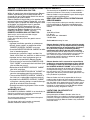
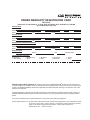
1
FOR YOUR SAFETY If you smell gas: 1. Open windows. 2. DO NOT try to light any appliance. 3. DO NOT use electrical switches. 4. DO NOT use any telephone in your building. 5. Leave the building. 6. Immediately call your local gas supplier after leaving the building. Follow the gas suppliers instructions. 7. If you cannot reach your gas supplier, call the Fire Department. WARNING ® Caribe Gas-Fired, Low-Intensity Infrared Heaters for Residential Garages and Light Industrial/Commercial Applications CGTH-30 CGTH-40 CGTH-50 Fire Hazard Do not store or use gasoline or other flammable vapors and liquids in the vicinity of this or any other appliance. Some objects will catch fire or explode when placed close to heater. Failure to follow these instructions can result in death, injury or property damage. Use and Care Manual WARNING Improper installation, adjustment, alteration, service or maintenance can result in death, injury or property damage. Read the Installation, Operation and Service Manual thoroughly before installing or servicing this equipment. Installation must be done by a contractor qualified in the installation and service of gas-fired heating equipment or your gas supplier. Installer Please take the time to read and understand these instructions prior to any installation. Installer must give a copy of this manual to the owner. Owner Keep this manual in a safe place in order to provide your serviceman with necessary information. Roberts-Gordon, LLC 1250 William Street P.O. Box 44 Buffalo, New York 14240-0044 Telephone: 716.852.4400 Fax: 716.852.0854 Toll Free: 800.828.7450 Quality in Any Language™ © Copyright 2007 Roberts-Gordon www.rg-inc.com P/N 180101NA Rev. B 1/07 TABLE OF CONTENTS SECTION 1: Before You Begin ............................................... 1 1.1 Read This Manual ........................................................ 1 1.2 Questions, Comments or Suggestions......................... 1 SECTION 2: Heater Safety...................................................... 2 SECTION 3: Introduction........................................................ 3 3.1 About Roberts-Gordon ................................................ 3 3.2 About the Heater.......................................................... 3 3.3 Unpacking the Heater .................................................. 3 3.4 Components Identification ........................................... 4 3.5 Where Can the Heater Be Installed? ........................... 5 3.6 Where Can't the Heater Be Installed?.......................... 5 3.7 Installer's Responsibility .............................................. 5 SECTION 4: Before Using The Heater ................................... 6 4.1 System Requirements.................................................. 6 4.2 Gas Service Requirements:......................................... 6 4.3 Electrical Service Requirements.................................. 6 4.4 Venting Requirements.................................................. 7 4.5 Non-Residential Installations ....................................... 7 4.6 Heater Location ........................................................... 8 SECTION 5: Using The Heater ............................................... 9 5.1 Required Safe Distances from Combustibles............... 9 5.2 Protective Grille.......................................................... 13 5.3 Rear Movable Hanger Limits ..................................... 14 5.4 Operating Instructions................................................ 15 5.5 To Turn Off Gas To Heater ......................................... 15 5.6 Sequence of Operation.............................................. 16 5.7 Venting....................................................................... 16 SECTION 6: Caring For The Heater ..................................... 18 6.1 Annual Inspection ...................................................... 18 6.2 Monthly Inspection..................................................... 18 6.3 Maintenance Checklist............................................... 18 6.4 Basic Heater Care...................................................... 19 6.5 Replacement Parts .................................................... 19 SECTION 7: The ROBERTS GORDON® CARIBE® LIMITED Warranty............................................................. 21 © 2007 Roberts-Gordon, LLC All rights reserved. No part of this work covered by the copyrights herein may be reproduced or copied in any form or by any means - graphic, electronic, or mechanical, including photocopying, recording, taping or information storage and retrieval systems - without the written permission of Roberts-Gordon, LLC. Printed in the U.S.A. TABLE OF FIGURES Figure 1: Components Identification ......................................... 4 Figure 2: Balanced Flue............................................................ 7 Figure 3: Thermostat Tag ......................................................... 9 Figure 4: Horizontal Installation............................................... 10 Figure 5: 45° Tilted Installation................................................ 10 Figure 6: Vent Terminal Clearances ........................................ 11 Figure 7: Reflector and Grille .................................................. 13 Figure 8: Typical Installation.................................................... 14 Figure 9: Horizontal Venting Through The Wall ...................... 16 Figure 10: Horizontal Venting With An Elbow ......................... 17 Figure 11: Roof Venting .......................................................... 17 SECTION 1: BEFORE YOU BEGIN SECTION 1: BEFORE YOU BEGIN Thank you for purchasing a ROBERTS GORDON heating product. We are pleased you have chosen the CGTH Series overhead tube heater. In addition to the quality you receive from our company, you also receive over 30 years of infrared heating experience. ® For years of trouble-free operation from your heater, carefully read this Use & Care Manual. This Manual contains valuable information to help you use the heater safely and properly. Keep this manual in a safe place in case you have any questions or require service in the future. Also, since proof of purchase is required to obtain warranty coverage, keep the original sales receipt in a safe place. Remember to record the model and serial numbers of your heater below. Model and serial numbers are found on the rating tag affixed to the heater. See Page 10 for rating tag location. To obtain warranty service, please complete and mail the Owner Warranty Registration Card found on the last page of this manual. In addition to activating your warranty, registering your heater enables us to contact you with safety and product updates. Model Number: Serial Number: Fuel: Installation Date: Installed By: Company Purchased From (if different from installer): Company Name Name Address Address Phine Phone Fax Fax E-mail E-mail 1.1 Read This Manual 1.2 Questions, Comments or Suggestions Read this manual carefully before installing or servic- Please direct any questions, comments or suggesing this equipment. Improper installation, servicing or tions to: Roberts-Gordon, LLC maintenance can result in death, injury or property 1250 William Street damage. Check the required safe distances from P.O. Box 44 combustibles given on the outside of each burner to Buffalo, New York 14240-0044 make sure that the product is suitable for your appliTelephone: 716.852.4400 cation. The required safe distances from combustiFax: 716.852.0854 bles are also found on Pages 9 and 10 of this Toll Free: 800.828.7450 manual. Installer must be a contractor qualified in the installation and service of gas-fired heating equipment. After the installation is complete, check product operation as provided in these instructions. 1 CGTH USE AND CARE MANUAL SECTION 2: HEATER SAFETY Your Safety is Important to Us! This symbol is used throughout the manual to notify you of possible fire, electrical or burn hazards. Please pay special attention when reading and following the warnings in these sections. Installation, Service and Annual Inspection of heater must be done by a contractor qualified in the installation and service of gas-fired heating equipment. WARNING Read this manual carefully before using the heater. Plug the heater into a grounded three-prong ceiling outlet. Do not install or service any part of the heater. Installation must be done by a contractor qualified in the installation and service of gas-fired heating equipment or your gas supplier. Installer must exhaust heater outside. Keep all persons, especially children, away from the heater. Keep the heater out of the weather. The heater is for indoor areas such as residential garages, workshops, hobby greenhouses, small warehouses, service centers or lobbies. Do not use the heater in living or sleeping areas such as a bedroom or basement. CAUTION Do not use heater in an area containing corrosive chemicals. Avoid the use of corrosive chemicals to ensure a longer life of the burner, tubing and other parts. Failure to follow these instructions can result in property damage. 2 SECTION 3: INTRODUCTION SECTION 3: INTRODUCTION 3.1 About Roberts-Gordon lifted from the carton at the same time. The burner should be lifted by gripping the bottom. The reflector of the heater should be lifted using the hanger. Roberts-Gordon pioneered low-intensity infrared heating systems in 1962 with the introduction of its 3.3.2 Safety revolutionary custom-engineered CORAYVAC system. After more than 40 years of infrared expertise in commercial and industrial applications, Roberts-Gordon now offers the CGTH-Series heater for use in residential garages and light industrial/commercial applications. ® WARNING 3.2 About the Heater The CGTH-Series is a factory-assembled, gas-fired, low-intensity heating system that incorporates a balanced flue. The system has been designed for easy installation and will provide years of economical operation and trouble-free service. Not only is infrared heat efficient, it also provides the most comfortable conditions in open areas, such as garages. Gas-Fired means it uses clean-burning natural or LP gas. Low-Intensity means that the radiant surface of the tube does not glow red. Instead, it operates at a lower temperature (less than 1000°F) and radiates energy at a lower intensity per square foot of radiating surface. The lower temperature and intensity levels are within a range that is most effective in establishing and maintaining personal comfort levels. An aluminum reflector directs the radiant energy downward to the occupied area. Cut Hazard Wear protective gloves when handling aluminum reflectors. Edges are sharp. Failure to follow these instructions can result in injury. Thin sheet metal parts, such as the reflector portion of the heater and the various venting components, have sharp edges. To prevent injury, the use of work gloves is recommended. The use of gloves will also prevent the transfer of body oils from the hands to the surface of the reflector. Balanced Flue means that the burner draws combustion air from outdoors and exhausts the products of combustion, also to the outdoors, through a shared opening. This is accomplished through two concentric tubes. Radiant refers to the energy radiated by the CGTHSeries heater. Because the energy is in the form of infrared rays, it does not directly heat the air. Instead, the rays heat objects such as the floor, cars, machines and people. The warm objects, in turn, heat the air. These combined features are the key to the exceptional comfort and fuel efficiency provided by the CGTH-Series heater. 3.3 Unpacking the Heater 3.3.1 Manpower Requirements To prevent personal injury and damage to the heater, two persons will be required to remove the heater from the carton. Both ends of the heater should be 3 CGTH USE AND CARE MANUAL 3.4 Components Identification FIGURE 1: Components Identification Nipple 3/8'' NPT Vent Collar Thermostat Connection Wall Termination Plate Venting Power Cord Burner Gas Line Front Fixed Hanger Reflector Manual Gas Shut-off Valve Service Door Heat Exchanger Rear Movable Hanger CGTH-Series by ® This thermostat controls your overhead tube heater. Keep burner, control compartment and reflector clean. Read your CGTH-Series Use and Care Manual (P/N 180101NA or GH80101NA) and follow all Safety Requirements which include checking your heater monthly. Installation, Service and Annual Inspection must be done by a contractor qualified in the installation and service of gas-fired heating equipment. Please call (716) 852-4400 (USA) or (905) 945-5403 (Canada) if you need a manual or have questions. Ce thermostat commande votre radiateur. Gardez le module de contrôle et le reflécteur propres. Lisez le manuel dutilisation et dentretien CGTH-Series (P/N 180101NA ou GH80101NA) et respectez tous les conseils de sécurité, notamment le contrôle mensuel du radiateur. Linstallation, l'entretien et linspection annuelle doivent être effectués par un agent agréé. Veuillez nous contactez au 716-852-4400 (USA) ou au 905-945-5403 (Canada) pour toutes questions ou demandes de manuel. WARNING ATTENTION MOUNT THERMOSTAT HERE Fire Hazard Risque d'incendie Some objects will catch fire or explode when placed close to heater. Certains objets placés près du radiateur peuvent s'enflammer ou exploser. MONTER LE THERMOSTAT ICI Keep all flammable objects, liquids and vapors the required safe distances away from heater. Keep children, clothing and furniture away from the heater. Tenir tous les objets, iquides et vapeurs inflammables à la distance de sécurité requise du radiateur. Surveiffer les enfants. Gardes les vêtements, les meubles loin de l'appareil. Failure to follow these instructions will result in death, injury or property damage. Le non-respect de ces consignes peut causer dommage au matériel. Required Safe Distances from Combustibles Distances de Dégagement par Rapport aux Combustibles Horizontal Mount Montage Horizontal 24" Min. (61 cm) Protective Grill A Rating Tag Éttiquette de Classement Front Fixed Hanger - Provides rigid support and mounting surface for the reflector. Holes are provided in the upper corners of the bulkhead to accommodate suspension hardware required for installation of the heater. C F B A 4 4 4 B 16 18 20 Modèle CGTH-30 CGTH-40 CGTH-50 A B C D E F 11 41 92 72 87 16 11 46 122 77 87 16 11 51 122 82 92 16 NOTES: 1. All dimensions are from the reflector. 2. Black numerals are in inches. Orange numerals are in centimeters. 3. Know your model number. Model number is found on the rating tag. (See horizontal mount drawing for location of rating tag). © Burner - Contains the electrical components (i.e. blower motor, power transformer, etc.) and gas distribution components (i.e. gas valve, etc.) that make the heater work. There are no owner serviceable items contained in this box. B Model CGTH-30 CGTH-40 CGTH-50 www.rg-inc.com C D E 36 28 34 48 30 34 48 32 36 F 6 6 6 45° Mount Montage à 45° A 24" Min. (61 cm) D A Approx. 45 ° F E NOTES: 1. Toutes les dimensions sont mesurées à partir du réflecteur. 2. Les chiffres noirs sont en pouces. Les chiffres oranges sont en centimètres. 3. Vous devrez connaître le numéro de votre modèle. Il se trouve sur létiquette de classement. (Voir le dessin du montage horizontal pour lemplacement de létiquette de classement). Printed in U.S.A./Imprimé aux Etats-Unis P/N 91037903 Rev F and gas distribution components. Gas Line - Must only be installed and serviced by a licensed contractor or gas fitter. Wall Termination Plate - Placed on the outside wall over the venting. Venting - Installer must properly exhaust the heater outside. The 5” outer duct carries fresh air to the burner. The 3” inner duct carries the products of combustion to the outside. Thermostat - 24 Volt Thermostat mounted with Reflector - The reflector is made from formed alumiSafety Tag. num and reflects the radiant energy downward, bathProtective Grille - Included with select models. See ing people and objects below. Page 13, Section 5.2 for details. Heat Exchanger - A U-shaped tube through which Vent Collar - Accommodates a 5" (125 mm) diamethe heated products of combustion pass. ter combustion air inlet duct that delivers fresh air to Rear Movable Hanger - Provides support for the tube the burner. The fresh air enters the burner through and reflector at the end that is furthest from the burner. the twelve equally spaced holes shown above. The The support may be moved (within limits) to accom3" (80 mm) diameter hole in the center of the flue colmodate hanging of the unit. lar accommodates the venting duct that carries the Service Door - To be removed only by a contractor products of combustion to be vented outdoors. qualified in the installation and service of gas-fired Nipple-3/8" (10 mm) NPT - Point at which the gas heating equipment or your gas supplier. Removal of supply is connected to the heater. this service door provides access to the electrical 4 SECTION 3: INTRODUCTION Thermostat Connection - Two terminals to which the thermostat wires will be connected. Power Cord - Includes a three-prong plug that must be connected to a dedicated and properly grounded three-prong ceiling outlet. 3.5 Where Can the Heater Be Installed? The CGTH-Series heater is intended for installation in the following areas: • Residential applications, such as: - garages - hobby greenhouses - workshops aspects of the installation are unclear, consult your ROBERTS GORDON independent distributor for clarification. The installer must furnish all needed materials that are not furnished as standard equipment. It is also the installer's responsibility to see that the materials and installation methods used result in a job that is workmanlike in appearance and is in compliance with the requirements of this manual. The installer must give this manual and the Installation, Operation and Service Manual to the owner. ® • Light industrial/commercial applications, such as: - entranceways - lobby areas - lunch rooms - aircraft hangars (See Page 7, Section 4.5.1 for restrictions) - public garages (See Page 7, Section 4.5.2 for restrictions) 3.6 Where Can't the Heater Be Installed? The CGTH-Series heater is not intended for installation in the following areas: • Residential living or sleeping areas • Basements Due to high temperatures, ensure that the heater area is kept clear of furniture, draperies, clothing or other combustible materials. Children and adults should be alerted to the hazard of high surface temperatures and should stay away to avoid burns and clothing ignition. Young children should be carefully supervised when they are in the same room as the heater. 3.7 Installer's Responsibility The CGTH-Series heater, the gas and electrical supplies, as well as the venting, must be installed in accordance with applicable specifications and codes. Only firms (or individuals) well qualified in this type of work should install the system. Consult local Building Inspectors, Fire Marshals or your local ROBERTS GORDON independent distributor for guidance. ® Use the information given in this manual together with the cited codes and regulations to perform the installation. The heater must be installed in accordance with the Minimum Required Safe Distance from Combustibles and must bevented outside. If any 5 CGTH USE AND CARE MANUAL SECTION 4: BEFORE USING THE HEATER The following information is included in the Installation Manual and applies to the installer at the time of installation. The warnings are included on the product. Because your safety is important to us, we include these warnings for your information. If you find your heater is not installed according to these warnings and codes, immediately contact the installer. for checking system gas pressure. 4.2.3 Meter and Service 4.1 System Requirements Meter and service must be large enough to handle all the heaters being installed plus any other connected load. The gas line which feeds the system must be large enough to supply the required gas with a maximum pressure drop of 1/2" wc When gas piping is not included in the layout drawing, the local gas supplier will usually help in planning the gas piping. This section provides the following information: 4.3 Electrical Service Requirements • Defines the gas, electric and venting requirements for the CGTH-Series heater. WARNING Electrical Shock Hazard Plug heater into grounded threeprong ceiling receptacle. • Specifies the national standards and applicable codes that apply to the gas, electric and venting requirements. Do not cut or remove the grounding prong from this plug. • Specifies the national standards and applicable codes that apply to non-residential installations. Do not use with an extension cord. Failure to follow these instructions can result in death or electrical shock. 4.2 Gas Service Requirements: Inlet Connection: 3/8" Male NPT Inlet Pressure Natural Gas: Minimum 5.0" wc Maximum 14.0" wc LP Gas (Propane): Minmum 11.0" wc Maximum 14.0" wc Manifold Pressure Natural Gas: 3.5" wc LP Gas (Propane): 10.5" wc The CGTH-Series heater requires a grounded threeprong electrical outlet to be installed within 18" of the rear surface of the heater’s burner box. It is recommended that the outlet for the heater be ceilingmounted and should be on a dedicated circuit. DO NOT use an electrical extension cord to operate the heater. Heater Rating: 120 VAC, 60 Hz, 1 Ø, 1 A 4.2.1 Gas Type 4.3.1 Grounding The type of gas appearing on the nameplate must be the type of gas used. Installation must comply with local codes and recommendations of the local gas company. United States: Refer to National Fuel Gas Code, ANSI Z223.1 - latest revision (same as NFPA 54). Canada: Refer to CSA B149.1 Natural Gas ans Propane Installation Code. The heater must be electrically grounded in accordance with the following codes: United States: Refer to National Electrical Code, ANSI/NFPA-70 - latest revision. Wiring must conform to the most current National Electrical Code and local ordinances. Canada: Refer to Canadian Electrical Code, CSA C22.1 Part 1 - latest revision. 4.2.2 Gas Supply Lines It is important to note that the CGTH-Series heater is controlled by a low voltage (24V AC) thermostat supplied with the heater. The control transformer located inside the burner supplies the necessary electrical power to operate the thermostat. No other electrical power to the thermostat is required. The size of the gas supply lines must comply with local codes and recommendations of the local gas company. United States: Refer to National Fuel Gas Code, ANSI Z223.1 - latest revision (same as NFPA 54). Canada: Refer to CSA B149.1 Natural Gas ans Propane Installation Code. A 1/8" NPT plugged tap must be installed in the gas line connection immediately upstream of the burner that is farthest from the gas supply meter. The tap is required 6 4.3.2 Thermostat SECTION 4: BEFORE USING THE HEATER 4.4 Venting Requirements The CGTH-Series heater must be installed with the venting system supplied or with the optional venting kit available from Roberts-Gordon. DO NOT connect this heater to a separate chimney, and do not common vent with any other fuel burning appliance. The CGTH-Series heater employs a balanced flue/air venting duct system and must conform to the following length requirements: Maximum Length: 10' (3 m) Minimum Length: 2' - 6" (.76 m) Maximum Elbows:Two with natural gas units, one with propane gas units 4.4.1 Venting Codes WARNING Carbon Monoxide Hazard Heater must be exhausted outside. Use materials supplied. This heater needs fresh air for safe operation and must be installed so there are provisions for adequate combustion and ventilation air. Failure to follow these instructions can result in death or injury. The location, size, installation and termination of vents, as well as the required safe distances from combustibles when penetrating combustible walls, must comply with local codes and recommendations of the local gas company. United States: Refer to National Fuel Gas Code, ANSI Z223.1 - latest revision (same as NFPA 54). Canada: Refer to CSA B149.1 Natural Gas ans Propane Installation Code. 4.4.2 Balanced Flue Construction FIGURE 2: Balanced Flue Outside Air Exterior Wall Exhaust Exhaust Outside Air 4.5 Non-Residential Installations 4.5.1 Aircraft Hangars The CGTH-Series heater may be used in certain areas of aircraft hangars. Installation in aircraft hangars must be in accordance with the following codes: United States: Refer to Standard for Aircraft Hangars, ANSI/ NFPA-409 - latest revision. Canada: Refer to Standard CSA B149.1 Natural Gas ans Propane Installation Code. • Heaters in aircraft storage or service areas must be installed a minimum of 10' (3 m) above the upper surface of wings or engine enclosures of the highest aircraft which may be housed in the hangar. (This should be measured from the bottom of the heater to the top of the wing, or engine enclosure, whichever is highest from the floor). • In other sections of aircraft hangars, such as shops or offices, heaters must be installed a minimum of 8' (2.4 m) above the floor. • Heaters installed in aircraft hangars shall be located so as not to be subject to damage by aircraft, cranes, movable scaffolding or other objects. • When installed over hoists, the required safe distances from combustibles must be maintained from the uppermost point of the combustible materials placed on the hoist. The balanced flue consists of a 3" (8 cm) diameter flue which is concentrically positioned inside a 5" (12.5 cm) diameter vent pipe (See Figure 2). The 5" (12.5 cm) diameter vent supplies outside air for com- 4.5.2 Public Garages bustion while the 3" (8 cm) diameter flue carries the The CGTH-Series heater may be used in public products of combustion from the heater. garages. Installation in public garages must be in accorThe balanced flue is applicable for both horizontal dance with the following codes: United States: Standard and vertical venting arrangements. Vertical venting for Parking Structures NFPA-88A - latest revision or the will require the optional roof venting kit available from Code for Motor Fuel Dispensing Facilities and Repair Roberts-Gordon. Garages, NFPA-30A - latest revision. Canada: Refer to CSA B149.1 Natural Gas ans Propane Installation Code. • Heaters must be installed a minimum of 8' (2.4 m) above the floor. Required safe distances to combus7 CGTH USE AND CARE MANUAL tibles must be maintained from vehicles parked below the heater. • When installed over hoists, the required safe distances from combustibles must be maintained from the uppermost point of the combustible materials placed on the hoist. 4.5.3 Hazardous Locations Where there is the possibility of exposure to combustible airborne material or vapor, consult the local Fire Marshal, the Fire Insurance Carrier or other authorities for approval of the proposed installation. 4.6 Heater Location It is the Installer’s Responsibility to choose a suitable mounting location for the heater. The Installer must follow the guidelines below as stated in the Installation Manual. Before using your heater, check the location. If the location does not follow these guidelines, do not use the heater. Immediately contact your installer. • The heater must meet the minimum mounting height requirement of 7' (2.1 m) above the floor. For aircraft hangars and public garages, the heater must meet the minimum mounting height requirement of 8' (2.4 m) above the floor. • The proposed mounting location allows for the required safe distances from combustibles such as vehicles, wood, gasoline and flammable objects, liquids and vapors. • The proposed location of the heater will not restrict motion of passageway doors or windows. • The proposed location will not interfere with operation of the overhead garage door, or allow the door to enter the required safe distances from combustibles. • The proposed location will provide the best coverage of the total area to be heated. • Consideration be given to the types of vehicles that will be parked in the garage (cars, vans, boats, RV's, etc.). • The proposed location will allow for the required safe distances from combustibles with respect to the vehicles parked in the garage. • The proposed location will allow the required utilities (i.e.: gas and electric) and venting to be installed (maximum vent length is 10' [3 m]). 8 • Sufficient clearances will exist to allow for easy access to the service door. • Overhead structural members (rafters, beams, etc.) are accessible for attaching the heater. SECTION 5: USING THE HEATER SECTION 5: USING THE HEATER 5.1 Required Safe Distances from Combustibles Once your heater is installed by a licensed contractor, you must remember to maintain the required safe distances from combustibles at all times. Combustibles are materials which may catch fire and include many common items such as your vehicle, wood and wood shavings, paper, rubber, fabrics, etc. Don’t forget these materials could be in the form of liquids and vapors or may be airborne. WARNING Fire Hazard Burn Hazard Some objects will catch fire Keep all persons, especially children, away Combustible materials such as those noted, and any or explode when placed close to heater. from heater. other combustible materials, must not be placed Keep all flammable objects, Do not touch any part of closer to any base or side of the CGTH-Series heater liquids and vapors the the heater. required safe distances to than the distances noted in the diagrams on the folHeater is very hot. combustibles away from lowing page. If you have any questions about the heater. Failure to follow these required safe distances from combustibles, or the instructions can result in Failure to follow these associated diagrams, please contact your installer, instructions can result in death, injury or property damage. death, injury or property ROBERTS GORDON independent distributor, or damage. Roberts-Gordon at 716.852.4400 or 1.800.828.7450 during normal business hours which are Monday through Friday, 8:15 a.m. to 4:45 p.m., Eastern Time. The warnings on this page appear on the heater and are also on the thermostat tag to serve as a constant For owner safety, a thermostat tag is supplied with reminder to maintain the required safe distances from the CGTH-Series as a permanent reminder of the combustibles at all times. If you do not have either importance of maintaining the required safe disthe label on your heater or the thermostat tag, immetances from combustibles. Instructions for installing the tag are located in the Installation, Operation and diately call your installer or Roberts-Gordon for Service manual. Immediately contact your ROBERTS replacement. ® GORDON independent distributor or Roberts-Gordon if the tag is missing. ® It is important to keep the required safe distances from combustibles at all times. Clearances from vehicles parked beneath heaters must be maintained. The thermostat tag (included with the heater) must be posted to identify any possible violation of the clearance distances from the heater in vehicle areas. Maximum allowable stacking height in storage areas should be identified with signs or appropriate markings. See Page 10, Figure 4 and Figure 5 for the required safe distances from combustibles. FIGURE 3: Thermostat Tag CGTH-Series by ® This thermostat controls your overhead tube heater. Keep burner, control compartment and reflector clean. Read your CGTH-Series Use and Care Manual (P/N 180101NA or GH80101NA) and follow all Safety Requirements which include checking your heater monthly. Installation, Service and Annual Inspection must be done by a contractor qualified in the installation and service of gas-fired heating equipment. Please call (716) 852-4400 (USA) or (905) 945-5403 (Canada) if you need a manual or have questions. Ce thermostat commande votre radiateur. Gardez le module de contrôle et le reflécteur propres. Lisez le manuel dutilisation et dentretien CGTH-Series (P/N 180101NA ou GH80101NA) et respectez tous les conseils de sécurité, notamment le contrôle mensuel du radiateur. Linstallation, l'entretien et linspection annuelle doivent être effectués par un agent agréé. Veuillez nous contactez au 716-852-4400 (USA) ou au 905-945-5403 (Canada) pour toutes questions ou demandes de manuel. WARNING ATTENTION MOUNT THERMOSTAT HERE Fire Hazard Risque d'incendie Some objects will catch fire or explode when placed close to heater. Certains objets placés près du radiateur peuvent s'enflammer ou exploser. MONTER LE THERMOSTAT ICI Keep all flammable objects, liquids and vapors the required safe distances away from heater. Keep children, clothing and furniture away from the heater. Tenir tous les objets, iquides et vapeurs inflammables à la distance de sécurité requise du radiateur. Surveiffer les enfants. Gardes les vêtements, les meubles loin de l'appareil. Failure to follow these instructions will result in death, injury or property damage. Le non-respect de ces consignes peut causer dommage au matériel. Required Safe Distances from Combustibles Distances de Dégagement par Rapport aux Combustibles Horizontal Mount Montage Horizontal 24" Min. (61 cm) A Rating Tag Éttiquette de Classement B C F B Model CGTH-30 CGTH-40 CGTH-50 A 4 4 4 B 16 18 20 Modèle CGTH-30 CGTH-40 CGTH-50 A B C D E F 11 41 92 72 87 16 11 46 122 77 87 16 11 51 122 82 92 16 NOTES: 1. All dimensions are from the reflector. 2. Black numerals are in inches. Orange numerals are in centimeters. 3. Know your model number. Model number is found on the rating tag. (See horizontal mount drawing for location of rating tag). © www.rg-inc.com C D E 36 28 34 48 30 34 48 32 36 F 6 6 6 45° Mount Montage à 45° A 24" Min. (61 cm) D A Approx. 45 ° F E NOTES: 1. Toutes les dimensions sont mesurées à partir du réflecteur. 2. Les chiffres noirs sont en pouces. Les chiffres oranges sont en centimètres. 3. Vous devrez connaître le numéro de votre modèle. Il se trouve sur létiquette de classement. (Voir le dessin du montage horizontal pour lemplacement de létiquette de classement). Printed in U.S.A./Imprimé aux Etats-Unis P/N 91037903 Rev F 9 CGTH USE AND CARE MANUAL Your heater may be installed in one of three ways: horizontal, 45° tilt left or 45° tilt right. Since the distances for the tilt installation are the same, the chart only shows one (the 45° tilt left). To determine the minimum required safe distances for your heater, you must know the mounting type and model number of your heater. FIGURE 4: Horizontal Installation 24" Min. (60 cm) A Rating Tag B C F B FIGURE 5: 45° Tilted Installation 24" Min. (60 cm) A A Approx. 45° D F E Required Safe Distances from Combustibles* Inches Metric (cm) C D E F A B C D Model A B E F CGTH-30 4 16 36 28 34 6 11 41 92 72 87 16 CGTH-40 4 18 48 30 34 6 11 46 122 77 87 16 CGTH-50 4 20 48 *All dimensions are from the reflector. 32 36 6 11 51 122 82 92 16 NOTE: All dimensions indicate the required safe distances from combustibles, dimension "C" and "E" DO NOT indicate the required mounting height. The minimum mounting height is 7' (2.1 m), except for aircraft hangars and public garages. (See Page 7, Sections 4.5.1 and 4.5.2.) Flue clearances from combustibles are zero. It is not necessary to provide additional clearance on penetrations through the wall or roof. Know your model number. Model number is found on the rating tag. 10 SECTION 5: USING THE HEATER FIGURE 6: Vent Terminal Clearances INSIDE AIL DET CORNER G V D H A V L E V B B B C FIXED CLOSED V F B V LE OPERAB V V I M X V X V J J B B V Vent Terminal X Air Supply Inlet Canadian Installations A Clearance above grade, veranda, porch, deck, or balcony B 1 Area Where Terminal Is Not Permitted US Installations 12" (30 cm) 12" (30 cm) Clearance to window or door that may be open 12" 9" C Clearance to permanently closed window 12" 12" D Vertical clearance to ventilated soffit located above the terminal within a horizontal distance of 2' (61 cm) from the center line of the terminal. 12" 12" E Clearance to Unventilated soffit 12" 12" F Clearance to Outside Corner * * G Clearance to inside 18" 18" corner 2 11 CGTH USE AND CARE MANUAL H Clearance to each side of center line extended above meter/regulator assembly 3' (91 cm) within a height 15' (4.5 m) above the meter/regulator assembly * I Clearance to service regulator vent outlet 3' (91 cm) * J Clearance to nonmechanical air supply inletto building or the combustion air inlet to any other appliance 12" (30 cm) 9" (23 cm) K Clearance to mechanical air supply inlet 6' (1.83 m) 3' (91 cm) above if within 10' (3 m) horizontally L Clearance above paved sidewalks or paved driveway located on private property 7' (2.13 m)+ 7’ (2.13 m)+ 12' (30 cm)** 12" (30 cm)** Clearance under M veranda, porch, deck, or balcony In accordance with the current CSA B149.1, Natural Gas and Propane Installation Code In accordance with the current ANSI Z223.1/NFPA 54, National Fuel Gas Code A vent shall not terminate directly above a sidewalk or paved driveway that is located between two single family dwellings and serves both dwellings. ** Permitted only if veranda, porch, deck, or balcony is fully open on a minimum of two sides beneath the floor. * For clearances not specified in ANSI Z223.1/NFPA 54 or CSA B149.1, one of the following shall be indicated: a) A minimum clearance value determined by testing in accordance with section 4.7.3, 6.5.5, 8.5.5; or; b) A reference to the following footnote: "Clearance in accordance with local installation codes and the requirements of the gas supplier." 1 2 + 12 SECTION 5: USING THE HEATER 5.2 Protective Grille • Do not touch the heater WARNING • Keep all persons, especially children, away from the heater. • Use of protective grille (included with select models) is recommended. Fire Hazard Burn Hazard Some objects will catch fire or explode when placed close to heater. Keep all persons, especially children, away from heater. Keep all flammable objects, liquids and vapors the minimum required clearances to combustibles away from heater. Do not touch any part of the heater. Failure to follow these instructions can result in death, injury or property damage. Heater is very hot. Failure to follow these instructions can result in severe injury. A protective grille is included with select models of the CGTH-Series heater. This grille is supplied in sections and must be installed on the underside of the reflector prior to operation. The Model CGTH-30 heater is 8' (2.5 m) long and requires installation of two protective grille sections and one grille endcap, while the Models CGTH-40 and CGTH-50 are 11' 6" (3.5 m) long and require three protective grille sections and one grille endcap. One grille has a formed end panel and is installed at the end of the reflector that is furthest from the burner box. The other grille has an open-end and is installed closest to the burner box. To purchase the protective grille for your heater, please contact your installer. FIGURE 7: Reflector and Grille Burner Front Fixed Hanger Reflector First Grille Sections Final Grille Section Grille End Cap 13 CGTH USE AND CARE MANUAL 5.3 Rear Movable Hanger Limits Figure 8 shows a typical installation of the CGTHSeries heater. The drawing specifies the allowable range of distance between the front fixed hanger and the rear movable hanger. The rear hangar should only be moved if the distance between both hangers is not within the allowable range. FIGURE 8: Typical Installation 1" (3 cm) Maximum Minimum Recommended for Servicing X 24" (61 cm) Suspension Points 15" (38 cm) Exterior Wall Burner Box 14 Reflector Minimum Mounting Height - 7' (2.1 m)* Vent Terminal Model CGTH-30 CGTH-40 CGTH-50 6" (15 cm) Minimum X Dimension Minimum 60" (1.5 m) 102" (2.5 m) 102" (2.5 m) Maximum 72" (1.8 m) 114" (2.9 m) 114" (2.9 m) (*) For minimum mounting height in aircraft hangars and public garages, See Page 7, Sections 4.5.1 and 4.5.2. SECTION 5: USING THE HEATER FOR YOUR SAFETY READ BEFORE OPERATING FOR YOUR SAFETY If you smell gas: 1. Open windows. 2. DO NOT try to light any appliance. 3. DO NOT use electrical switches. 4. DO NOT use any telephone in your building. 5. Leave the building. 6. Immediately call your local gas supplier after leaving the building. Follow the gas suppliers instructions. 7. If you cannot reach your gas supplier, call the Fire Department. WARNING Fire Hazard Do not store or use gasoline or other flammable vapors and liquids in the vicinity of this or any other appliance. Some objects will catch fire or explode when placed close to heater. Failure to follow these instructions can result in death, injury or property damage. 5.4 Operating Instructions. WARNING Electrical Shock Hazard Plug heater into grounded threeprong ceiling receptacle. Do not cut or remove the grounding prong from this plug. Do not use with an extension cord. Failure to follow these instructions can result in death or electrical shock. . WARNING Electrical Shock Hazard Disconnect electrical power before service or maintenance. Failure to follow these instructions can result in death or electrical shock. STOP! Read the safety information above. 1. Set the thermostat to the lowest setting. 2. Turn off all electric power to the heater. 3. Do not try to light the burner by hand. 4. Turn off the manual gas valve in the heater supply line. 1. This appliance does not have a pilot. It is equipped with an ignition device which automatically lights the burner. DO NOT try to light the burner by hand. 2. BEFORE OPRERATING smell all around the 5. Wait five (5) minutes to clear out any gas. If you appliance area for gas. Be sure to smell next to then smell gas, STOP! If you do not smell gas, the floor because some gas is heavier than air go to the next step. and will settle on the floor. 6. Open the manual gas valve in the heater supply 3. Use only your hand to push in or turn the gas line. control knob. Never use tools. If the knob will not push in or turn by hand, don’t try to repair it, call a qualified service technician. Force or 7. Turn on electric power to the heater. attempted repair may result in a fire or explo8. Set the thermostat to the desired setting. sion. 9. If the heater will not operate, See Section 5.5 4. DO NOT use this appliance if any part has been and call your service technician or gas supplier. under water. Immediately call a qualified service 5.5 To Turn Off Gas To Heater technician to inspect the appliance and replace 1. Set the thermostat to the lowest setting. any part of the control system and any gas control which has been under water. 15 CGTH USE AND CARE MANUAL 2. Turn off all electric power to the heater if service is to be performed. 3. Turn off the manual gas valve in the heater supply line. 5.6 Sequence of Operation 1. When the thermostat calls for heat, the blower motor will energize. 2. When the motor approaches nominal running speed, the pressure switch closes and activates the ignition module which in turn initiates the purge. 3. The ignition module then energizes the spark igniter. 4. When sparking begins, the gas valve is energized. 5. If a flame is detected, the gas valve remains open. When the call for heat is satisfied, the system control mechanism de-energizes and the gas valve is turned off. 6. If no flame is detected, the gas valve is closed, and a purge period begins. After the purge period, the ignition module energizes the spark igniter and the gas valve. If a flame is still not established, a third and final purge/ignition sequence is begun. After three failed attempts, the system control mechanism will lock out for a period of one hour or until the unit is reset. 7. Reset is accomplished by removing power from the heater for at least five seconds. 8. With a three-try module, when the flame is established and then lost on the first or second trial, the gas valve will automatically turn off. A purge and trial for ignition will then occur. 5.7 Venting As mentioned on Page 5, Section 3.7, it is the Installer’s Responsibility to properly vent (exhaust) the heater outside. Please make sure your heater is vented. If it is not vented, do not use the heater. Immediately call your installer. Your heater may be vented in one of three ways: horizontal through the wall, horizontal with an elbow through the wall or vertical through the roof. You should know the way your heater is vented. Refer to the following drawings to determine the type of venting you have. If you are not sure, please contact your installer. WARNING Carbon Monoxide Hazard Heater must be exhausted outside. Use materials supplied. This heater needs fresh air for safe operation and must be installed so there are provisions for adequate combustion and ventilation air. Failure to follow these instructions can result in death or injury. FIGURE 9: Horizontal Venting Through The Wall Side View 3" (7.6 cm) pipe is slid through end of terminal 10' (3 m) max. 2' 6" (76.2 cm) min. Slope down 1/4" (.6 cm) per foot towards vent terminal Vent Terminal Heater Bird Screen Optional Vent Extension 16 6" (15.2 cm) min. 5" (12.5 cm) Air Supply Pipe 3" (7.6 cm) Flue Pipe SECTION 5: USING THE HEATER FIGURE 10: Horizontal Venting With An Elbow - Top View Optional Vent Extension 3" (7.6 cm) 5" (12.5 cm) Vent Terminal 3" (7.6 cm) pipe is slid through end of terminal 6" (15.2 cm) Minimum Heater FIGURE 11: Roof Venting VERTICAL 30" (76.2 cm) minimum above roof Roof Terminal 90506008 Roof Storm Collar Vent Clamp A 90506001 90506003 90506004 90506005 90506012 Burner B Use Table 2 to select lengths for A & B 17 CGTH USE AND CARE MANUAL SECTION 6: CARING FOR THE HEATER To ensure your safety and years of trouble-free operation of the heater, inspections by both the contractor and owner are essential. 6.1 Annual Inspection Before every heating season, a licensed contractor must perform a thorough inspection of the heater. s, electrical and thermostat connections as well as the venting and suspensions are some of the areas requiring inspection. 6.2 Monthly Inspection The owner must visually inspect the heater each month using the checklist on Page 18, Section 6.3. Check only the itemson this list and follow the instructions given. 6.3 Maintenance Checklist WARNING Turn off gas and electrical supplies before performing service or maintenance. Failure to follow these instructions can result in death, injury or property damage. Installation Code and Annual Inspections: All installations and service of ROBERTS GORDON products must be performed by a contractor qualified in the installation and service of products sold and supplied by Roberts-Gordon and conform to all requirements set forth in the ROBERTS GORDON manuals and all applicable governmental authorities pertaining to the installation, service and operation of the equipment. To help facilitate optimum performance and safety, Roberts-Gordon recommends that a qualified contractor annually inspect your ROBERTS GORDON products and perform service where necessary, using only replacement parts sold and supplied by Roberts-Gordon LLC. ® ® ® The Vicinity of the Heater Vehicles and Other Objects Do not store or use flammable objects, liquids or vapors near the heater. Immediately remove these items if they are present. Keep the heater clear of clothing, furniture, draperies or other combustible materials. Children and adults should be alerted to the hazards of high surface temperatures and should stay away to avoid burns and clothing ignition. Young children should be carefully supervised when they are in the same room as the heater. Maintain the clearances to combustibles. Do not hang anything from, or place anything on, the heater. Make sure nothing is lodged underneath the reflector, in between the tubes or in the decorative or protective grilles (included with select models). Power Cord Inside Venting Immediately remove objects in violation of the clearances to combustibles. There should be no exposed wire on the cord or damage on the plug. Venting must be intact. Using a flashlight, look for obstructions, cracks on the pipe, gaps in the sealed areas or corrosion. The area must be free of dirt and dust. Outside Air Inlet Remove any carbon deposits or scale using a wire brush. Inlet must be intact. Look for obstructions, cracks on the pipe, gaps in the sealed areas or corrosion. Tubes The area must be free of dirt and dust. Clean and reinstall as required. Make sure there are no cracks. Gas Line Contact a licensed contractor for repair. Contact a licensed contractor for repair. 18 SECTION 6: MCARING FOR THE HEATER Thermostat There should be no exposed wire or damage to the thermostat. Safety wall tag must be mounted over thermostat. Suspension Points Contact a licensed contractor for repair. Make sure the heater is hanging securely. Look for signs of wear on the chain or ceiling. Contact a licensed contractor for repair. Protective Grille (included The grille must be securely attached. in select models) Contact a licensed contractor for repair. Bird Screen Make sure nothing is lodged in the screen. Immediatly remove objects. The screen must be securely attached. If the screen is loose or off, contract a licensed contractor for repair. See Page 16, Figure 9 for location of bird screen. 6.4 Basic Heater Care • Make sure the heater is off and cool. Dust the burner, reflector and control compartment off with a dry cloth. Increase cleaning frequency if the heater is in an area where excessive dirt, dust or lint material etc. can build up. • Do not use the heater in an area containing corrosive chemicals. • Do not install or use the heater outdoors. • Do not use the heater if any part has been under water. Immediately call a licensed contractor to inspect the heater and to replace any part of the control system which has been under water. WARNING Burn Hazard Do not touch any part of the heater when running. Heater is very hot. Heater must be off and cool before cleaning. Failure to follow these instructions can result in injury. • Do not paint any part of the heater. WARNING 6.5 Replacement Parts Use only genuine ROBERTS GORDON replacement parts. ® Use of parts not specified by Roberts-Gordon voids the warranty. Cut Hazard Do not touch edges of heater. Edges are sharp. Failure to follow these instructions can result in injury. 19 CGTH USE AND CARE MANUAL 20 SECTION 7: THE ROBERTS GORDON CARIBE LIMITED WARRANTY ® ® SECTION 7: THE ROBERTS GORDON CARIBE LIMITED WARRANTY The ownership of the ROBERTS GORDON CARIBE is ROBERTS-GORDON WILL PAY FOR: moved or transferred. This warranty is nontransferable. Within 42 months from date of shipment from RobertsGordon, replacement parts will be provided free of Roberts-Gordon is not permitted to inspect the damaged charge for any part of the product which fails due to a controller and/or component parts. manufacturing or material defect. READ YOUR INSTALLATION, OPERATION AND Roberts-Gordon will require the part in question to be returned to the factory. Roberts-Gordon will, at its sole SERVICE MANUAL discretion, repair or replace after determining the nature If you have questions about your controller, contact your of the defect and disposition of part in question. installing professional. Should you need Replacement Parts or have additional questions, call or write RobertsROBERTS GORDON Replacement Parts are Gordon: warranted for a period of 18 months from date of shipment from Roberts-Gordon or the remaining ROBERTS GORDON CARIBE warranty. U.S.A. 1250 William Street ROBERTS-GORDON WILL NOT PAY FOR: ® ® ® ® ® ® ® Service trips, service calls and labor charges. Shipment of replacement parts. Claims where the total price of the goods have not been paid. Damage due to: • Improper installation, operation or maintenance. • Misuse, abuse, neglect, or modification of the ROBERTS GORDON® CARIBE® in any way. • Use of the ROBERTS GORDON® CARIBE® for other than its intended purpose. • Incorrect gas or electrical supply, accident, fire, floods, acts of God, war, terrorism, or other casualty. • Improper service, use of replacement parts or accessories not specified by Roberts-Gordon. • Failure to install or maintain the ROBERTS GORDON® CARIBE® as directed in the Installation, Operation and Service manual. • Relocation of the ROBERTS GORDON® CARIBE® after initial installation. • The use of the ROBERTS GORDON® CARIBE® in a corrosive atmosphere containing contaminants. • The use of the ROBERTS GORDON® CARIBE® in the vicinity of a combustible or explosive material. • Any defect in the ROBERTS GORDON® CARIBE® arising from a drawing, design, or specification supplied by or on behalf of the consumer. • Damage incurred during shipment. Claim must be filed with carrier. WARRANTY IS VOID IF: The ROBERTS GORDON® CARIBE® is not installed by an electrician qualified in the installation and service of control systems for heating equipment. You cannot prove original purchase date and required annual maintenance history. The data plate and/or serial number are removed, defaced, modified or altered in any way. P.O. Box 44 Buffalo, New York 14240-0044 716.852.4400 On the web at: www.rg-inc.com Roberts-Gordon's liability, and your exclusive remedy, under this warranty or any implied warranty (including the implied warranties of merchantability and fitness for a particular purpose) is limited to providing replacement parts during the term of this warranty. Some jurisdictions do not allow limitations on how long an implied warranty lasts, so this limitation may not apply to you. There are no rights, warranties or conditions, expressed or implied, statutory or otherwise, other than those contained in this warranty. Roberts-Gordon shall in no event be responsible for incidental or consequential damages or incur liability for damages in excess of the amount paid by you for the ROBERTS GORDON® CARIBE®. Some jurisdictions do not allow the exclusion or limitation of incidental or consequential damages, so this limitation or exclusion may not apply to you. This warranty gives you specific legal rights, and you may also have other rights which vary from jurisdiction to jurisdiction. Roberts-Gordon shall not be responsible for failure to perform under the terms of this warranty if caused by circumstances out of its control, including but not limited to war, fire, flood, strike, government or court orders, acts of God, terrorism, unavailability of supplies, parts or power. No person is authorized to assume for Roberts-Gordon any other warranty, obligation or liability. LIMITATIONS ON AUTHORITY OF REPRESENTATIVES: No representative of Roberts-Gordon, other than an Executive Officer, has authority to change or extend these provisions. Changes or extensions shall be binding only if confirmed in writing by Roberts-Gordon's duly authorized Executive Officer. 21 ® OWNER WARRANTY REGISTRATION CARD Mail or Fax to: Roberts Gordon, LLC 1250 William Street, P.O. Box 44 Buffalo, NY 14240-0044 Phone: 716-852-4400 Fax: 716-852-0854 Toll Free: 800-828-7450 www.rg-inc.com About the Owner: Name: Address: City: State: Zip Code: Phone: Fax: E-mail: About the Installer: Name: Address: Phone: City: Fax: Purchased From (if different than installer): Name: Address: Phone: Fax: About your Heater: Model#: City: Zip Code: State: Zip Code: E-mail: Serial #: Type of Installation (check one): o Automotive o Manufacturing o Public Building o Office State: E-mail: o Warehouse o Retail Fuel: Installation Date: o Recreational o Agricultural o Aircraft o Other Installation Code and Annual Inspections: All installations and service of ROBERTS GORDON® products must be performed by a contractor qualified in the installation and service of products sold and supplied by Roberts-Gordon and conform to all requirements set forth in the ROBERTS GORDON® manuals and all applicable governmental authorities pertaining to the installation, service and operation of the equipment. To help facilitate optimum performance and safety, Roberts-Gordon recommends that a qualified contractor annually inspect your ROBERTS GORDON® products and perform service where necessary, using only replacement parts sold and supplied by RobertsGordon. This product is intended to assist licensed professionals in the exercise of their professional judgement. © 2007 Roberts-Gordon, LLC - All rights reserved. No part of this work covered by the copyrights herein my be reproduced or copied in any form or by any means graphic, electronic, or mechanical, including photcopying, recording, taping, or information storage and retrieval systems without written permission of Roberts Gordon, LLC. Printed in the U.S.A.