1
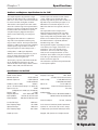
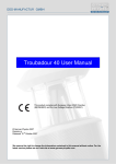
Users Guide /532E 531E 531E and 532E Graphic Equalizers 531E /532E Table of Contents Chapter 1 Introduction 1 Chapter 2 Operator Safety Summary 2 Chapter 3 Fast Set-Up 3 Chapter 4 Front Panel Controls 4 Chapter 5 Rear Panel Connections 7 Chapter 6 Troubleshooting 8 Chapter 7 Specifications 9 Chapter 8 Warranty and Service 11 Appendix A Flow Chart 13 Appendix B Input/Output Connections 14 Appendix C Declaration of Conformity 15 Rev A.02, 21 July, 1997 Symetrix part number 53531E0A02 Subject to change at our whim and fancy without notice. ©1996, Symetrix, Inc. All right reserved. Symetrix is a registered trademark of Symetrix, Inc. Mention of third-party products is for informational purposes only and constitutes neither an endorsement nor a recommendation. Symetrix assumes no responsibility with regard to the performance or use of these products. Under copyright laws, no part of this manual may be reproduced or transmitted in any form or by any means, electronic or mechanical, including photcopying, scanning, recording or by any information storage and retrieval system, without permission, in writing, from Symetrix, Inc. i Symetrix Inc. 14926 35th Ave. West Lynnwood, WA 98037 USA Tel (425) 787-3222 Fax (425) 787-3211 Email [email protected] Website www.symetrixaudio.com Chapter 1 Introduction Thank you for choosing a Symetrix Graphic Equalizer. We think you will be glad that you made this choice because, out of the sea of graphic eqs that you might have purchased, the 531E and 532E are the only affordable equalizers that offer truly professional performance. lowest noise floor of any graphic equalizer in the world, ultra-accurate summing, and minimal ringing and phase shift. The total harmonic distortion is less than 0.002%. Translation: the 531E and 532E are clean, clear, and musical-sounding. To ensure the highest level of year-after-year performance, we build the 531E and 532E to touring standards. Double sided, glass epoxy circuit boards, metal shaft, plastic film slide potentiometers, gold-plated XLR connectors, and a heavy duty all-steel chassis deliver rugged reliability. You dont have to treat these with kid gloves. How did we do this? First, because our design team believes that no one should have to settle for good enough, they threw out the conventional design ideas and started from scratch. The result: a highly advanced filter topology that delivers extremely low distortion and noise, even at very high signal levels. Second, our state-of-the-art facility gives us the ability to build quickly, consistently, and in high volume, allowing us to keep our prices low. In addition, the 531E and 532E make extensive use of surface-mount components. This allows us to cram more circuitry onto a smaller circuit board, further reducing costs. In fact, the 531E and 532E are a purists dream - audiophile sound quality, uncluttered control surface, and rugged reliability in one package. They offer thirty-one filter bands per channel on ISO 1/3rd octave centers. Through the use of a global range switch, each band delivers either 6dB or 12dB of cut or boost. The grounded center detent position on each band serves as an on/off switch that completely removes that band from the audio signal path. In addition, they sport 12dB per octave High Cut and Low Cut filters. Each has a sweepable cutoff frequency and a control range that extends well into the sub/ultrasonic. We recommend that you read this manual cover-to-cover. Youll find the answers to most of your questions inside. However, if you are in a hurry, go directly to the Fast First-Time Setup section. It will get you started quickly. Should you have any comments or questions, please do not hesitate to contact us at the numbers/addresses below. Your calls are always welcome. Of course, the controls and features are secondary to the all important question: How does it sound? Consider the following facts. Our proprietary filter technology delivers the 20 531E GRAPHIC EQUALIZER LOW CUT U CLIP 50 63 80 100 125 160 200 250 315 400 500 630 800 1K 1.25K 1.6K 2K 2.5K 3.15K 4K 5K 6.3K 8K 10K 12.5K 16K 20K +12 +6 +6 +12 +6 +3 +3 +6 22 50 6 260 HIGH CUT 18K MODE 10dB +15 0 0 42K 5K 8 115 ±12dB 0dB -∞ 40 Email [email protected] CUT FILTERS INPUT -20dB 31.5 Fax 425 787 3211 531E LEVEL 25 Phone 425 787 3222 3K 65K BYPASS ±6dB POWER -6 -3 -3 -6 -12 -6 CH1 LEVEL CH1 CUT FILTERS -6 -12 20 25 31.5 40 50 63 80 100 125 160 200 20 25 31.5 40 50 63 80 100 125 160 200 250 315 400 500 630 800 1K 1.25K 1.6K 250 315 400 500 630 800 1K 1.25K 1.6K 2K 2.5K 3.15K 4K 2K 2.5K 3.15K 4K 5K 6.3K 8K 10K 12.5K 16K 20K 5K 6.3K 8K 10K 12.5K 16K 20K +6 +12 LOW CUT INPUT U CLIP 22 HIGH CUT CH1 MODE 18K 50 10dB 5K -20dB ∞ 6 +15 0 ±12dB 0dB 532 E 0 42K 115 8 3K 260 -6 -12 BYPASS ±6dB 65K 20 GRAPHIC EQUALIZER CH2 LEVEL 25 31.5 40 50 63 80 100 125 160 200 250 315 400 500 630 800 1K 1.25K 1.6K 2K 2.5K 3.15K 4K 5K 6.3K 8K 10K 12.5K 16K 20K CH2 CUT FILTERS +6 +12 LOW CUT INPUT U CLIP 22 HIGH CUT CH2 MODE 18K 50 10dB 115 ∞ +15 6 260 0 ±12dB 0dB -20dB POWER 0 42K 5K 8 3K 65K -6 -12 BYPASS ±6dB 20 25 31.5 40 50 63 80 100 125 160 200 250 315 400 500 630 800 1K 1.25K 1.6K 2K 2.5K 3.15K 4K 5K 6.3K 8K /532E The details are worth noting, too. High-contrast front panel graphics make your control settings easy to read even in a darkened concert hall. Servo-balanced outputs remove all DC offset from the 531E or 532Es output. This eliminates the need for DC blocking capacitors in the signal path while improving noise, distortion, and low-frequency performance. Of course, the 531E and 532E incorporate a highcurrent, internal power supply with an IECtype detachable power cord. No wall warts here! 10K 12.5K 16K 20K 1 Operator Safety Summary The information in this summary is intended for persons who operate the equipment as well as repair personnel. Specific warnings and cautions are found throughout this manual wherever they may apply; they do not appear in this summary. The notational conventions used in this manual and on the equipment itself are described in the following paragraphs. Equipment Markings CAUTION RISK OF ELECTRIC SHOCK DO NOT OPEN TO REDUCE THE RISK OF FIRE OR SHOCK DO NOT EXPOSE WARNING: ELECTRIC THIS EQUIPMENT TO RAIN OR MOISTURE DE CHOC ELECTRIQUE AVIS: RISQUE NE PAS OUVRIR SEE OWNERS MANUAL. VOIR CAHIER D’INSTRUCTIONS. No user serviceable parts inside. Refer servicing to qualified service personnel. Il ne se trouve a l’interieur aucune piece pourvant entre reparée l’usager. S’adresser a un reparateur compétent. 531E /532E The lightning flash with arrowhead symbol within an equilateral triangle is intended to alert the user of the presence of uninsulated "dangerous voltage" within the product's enclosure that may be of sufficient magnitude to constitute a risk of electric shock to persons. The exclamation point within an equilateral triangle is intended to alert the user of the presence of important operating and maintenance (servicing) instructions in the literature accompanying the product (i.e. this manual). Caution To prevent electric shock, do not use the polarized plug supplied with the unit with any extension cord, receptacle, or other outlet unless the blades can be fully inserted. Terms Several notational conventions are used in this manual. Some paragraphs may use Note, Caution, or Warning as a heading or certain typefaces and capitalization are used to identify certain words. These are: Note 2 Identifies information that needs extra emphasis. A Note generally supplies extra information to help you to better use the product. Chapter 2 Caution Identifies information that, if not heeded, may cause damage to the Symetrix product or other equip ment in your system. Warning Identifies information that, if ignored, may be hazardous to your health or that of others. CAPITALS Controls, switches or other markings on the product's chassis. Boldface Strong emphasis. Power source - This product is intended to operate from a power source that does not apply more than 255Vrms between the power supply conductors or between either power supply conductor and ground. A protective ground connection, by way of the grounding conductor in the power cord, is essential for safe operation. Danger from loss of ground - If the protective ground connection is lost, all accessible conductive parts, including knobs and controls that may appear to be insulated, can render an electric shock. Proper power cord - Use only the power cord specified for the product. Use only a power cord that is in good condition. Operating location - Do not operate this equipment under any of the following conditions: explosive atmospheres, in wet locations, in inclement weather, improper or unknown AC mains voltage, or if improperly fused. Stay out of the box - To avoid personal injury or injury to others, do not remove the product covers or panels. Do not operate the product without the covers and panels properly installed. Chapter 3 Fast Set-Up This section is for those of you who are in too much of a hurry to read the rest of the manual. It provides just enough information to get the Graphic Equalizer hooked up and working in your sound system. Set all the graphic EQ slide potentiometers at 0dB, center detent position. Set LOW CUT control fully counterclockwise and the HIGH CUT control fully clockwise. Set the MODE switch to +/-12dB. Connect equalizer to AC power. Connect the audio inputs and outputs. See chapter 5 if you need more information. Let er rip. Now read the rest of this manual. /532E Set the INPUT L EVEL control at the unity gain setting . This is noted as U at the 12:00 position. 531E 3 Front Panel Controls Chapter 4 FRONT PANEL LEVEL CUT FILTERS LOW CUT INPUT U CLIP 22 HIGH CUT 18K 50 42K 5K 115 0dB -20dB -∞ +15 6 260 3K 65K POWER Input Level control - Use this control to adjust the 531E/532Es input sensitivity. The range is -∞ (infinity) to + 15dB. You can do three useful things with this knob: 1) Turn the knob down completely to mute your sound system - this can be very useful during troubleshooting, or if your console lacks an output mute switch. 2) Turn it down a little to give yourself enough headroom to make massive boosts in the EQ section without clipping. 531E /532E 3) Turn the knob up a little to boost a lowlevel input signal - this maximizes your signal to noise ratio. Note: This feature, like everything else on the unit, will be bypassed if the 531E/ 532E loses power or gets disconnected from AC power. Output Level Meter - The four segment LED meter is designed to give you a quick, general idea about the level of the 531E/532Es output. The bottom LED at -20dBu is a signal present indicator. The next two LEDs, at 0dBu and +10dBu show the activity of a signal at nominal to somewhat hot line levels. The top LED, labeled CLIP, will light when a +20 dBu signal is detected at the input buffer amp or output stage, though the 531E and 532E actually clip at +22dBu. Consider the CLIP LED a slightly early warning light. Note: If the INPUT LEVEL control is turned all the way down and you send a very hot input signal (greater than +20dBu) into the equalizers input, the CLIP LED will illuminate even though there will be no output signal. This will occur because the input buffer amp, which is before the INPUT LEVEL control, is one 4 Low Cut Filter - Diagram 1 illustrates the 12dB per octave ±12dB BYPASS low-frequency rolloff filter. This ±6dB filter is good for several things. It protects the low-frequency drivers -6 -3 in your sound system by removing potentially damaging subsonic audio material. This will also increase the efficiency of the amplifiers - why make them amplify signals that the speakers cannot reproduce? It can also clean up an overly muddy sounding mix or improve speech intelligibility in announce systems by removing excessive low-frequency audio material. The range of this control is 6 Hz to 260 Hz. MODE 10dB 8 of the points at which the CLIP LED detects excessive signal levels. 0 High Cut Filter - Diagram 2 shows the range of the 12dB per octave high-frequency rolloff filter (3kHz to 65kHz). Use this control to remove unwanted noise or hiss that is greater in frequency than the highest frequency content of the program material you are trying to reproduce. This is especially pertinent to speech reinforcement and paging systems. Mode Switch - This space-saving, three position toggle switch controls the cut/boost range of the faders AND functions as an EQ BYPASS when set in the middle position. If you require very fine cut and boost control for critical system voicing, put this switch in the +/-6dB mode. Permanent installations such as churches or performing arts theaters would be a good place to use this mode. The +/-12dB mode is most useful for concert and club sound applications where quick (and sometimes extreme) control is desired. This, of course, will reduce the resolution of the fader, but the 60mm, long-throw faders on the 531E provide more than adequate resolution for most applications. In addition, we have adjusted the control taper so that the majority of the fader throw is dedicated to the +/- 6dB range, giving you greater resolution in that crucial area. t AUDIO PRECISION 531E AMPL(dBu) vs FREQ(Hz) AUDIO PRECISION 531E 23 MAY 96 10:49:15 20.000 20.000 15.000 15.000 10.000 10.000 5.0000 5.0000 0.0 0.0 -5.000 -5.000 -10.00 -10.00 -15.00 -15.00 AMPL(dBu) vs FREQ(Hz) 23 MAY 96 10:54:00 -20.00 -20.00 20 100 1k 10k 20 20k 25 31.5 40 50 63 80 100 125 160 200 1k 10k 20k Diagram 2 - High Frequency Rolloff Filter Diagram 1 - Low Frequency Rolloff Filter 20 100 250 315 400 500 630 800 1K 1.25K 1.6K 2K 2.5K 3.15K 4K 5K 6.3K 8K 10K 12.5K 16K 20K +12 +6 +6 +12 +6 +3 +3 +6 MODE 0 0 ±12dB BYPASS ±6dB -6 -3 -3 -6 -12 -6 -6 -12 20 25 31.5 40 50 63 80 100 125 160 200 20 25 31.5 40 50 63 80 100 125 160 200 250 315 250 315 400 500 630 800 1K 1.25K 1.6K 2K 2.5K 3.15K 4K 400 500 630 800 1K 1.25K 1.6K 2K 2.5K 3.15K 4K 5K 6.3K 5K 6.3K 8K 10K 12.5K 16K 20K 8K 10K 12.5K 16K 20K +6 +12 CH1 MODE 0 0 -6 -12 BYPASS ±6dB 20 25 31.5 40 50 63 80 100 125 160 200 250 315 400 500 630 800 1K 1.25K 1.6K 2K 2.5K 3.15K 4K 5K 6.3K 8K 10K 12.5K 16K 20K +6 +12 CH2 MODE 0 0 ±12dB -6 -12 BYPASS ±6dB 25 31.5 40 50 63 80 100 125 160 200 250 315 400 500 The Graphic Equalizer - The 531E/532E has 31 filter bands on ISO 1/3rd octave centers. The lowest filter band is on 20hz, the highest is 20kHz. Note the dual cut/boost scale on the side of the fader bank - the different scales correspond to the +/- 6dB and +/- 12dB positions of the MODE switch. Applied correctly, the graphic equalizer is a useful and powerful tool. It can make a mediocre system sound good. It can make a good system great. However, used incorrectly, it can make even a great system sound terrible. 630 800 1K 1.25K 1.6K 2K 2.5K 3.15K 4K 5K 6.3K 8K 10K 12.5K 16K 20K With this in mind, we would like to offer some tips to get you started in the right direction. Tip #1 Always listen to the PA system with the graphic EQ in bypass before you start fiddling with the sliders because many frequency response problems are actually something else entirely. If something sounds wrong, check your entire PA system for proper hookup and performance BEFORE you start working with the equalizer. For example: 531E 20 /532E ±12dB 5 531E /532E m Make sure that all the speakers are working properly. Check each driver within an enclosure separately. Large sound systems may have many identical drivers in an array, making it hard to pinpoint blown, or out-ofphase drivers by ear. m Adjust your overall system gain structure so that all of the components in the signal path are operating at nominal levels. m Check your cabling! The vast majority of sound system problems are related to cables. Intermittent connections, polarity reverses, bad grounds, shorts, etc. are all examples of problems that can manifest themselves as frequency response problems. For instance, if the cable feeding your stage left subwoofer array is polarity reversed, causing the left subwoofer array to be out-of-phase with the right subwoofer array, you will percieve this as a lack of adequate low end power. Obviously, no amount of work with the graphic equalizer will fix this problem. Of course, the larger the system, the more there is to check. Be thorough. the graphic EQ. Tip #3 Whether you tune your system using the pink noise/spectrum analyzer method, or by playing music and using your ears, you should always do this at roughly the same volume that you expect to be running the system during the actual show. This is important because the frequency response of the human ear varies with sound pressure level. This phenomenon is well documented, first by Fletcher and Munson (and their eponymous curves) and later (and more accurately) by Robinson and Dodson. Tip #4 Cut and boost only at the frequency desired (one at a time)- do not move entire groups of sliders indiscriminately because this leads to: The dreaded fader creep! No, this is not a name for the guy who stands behind the mixing console. Rather, it is the situation in which you find yourself appyling huge amounts of cut or boost using several (or many) adjacent bands, yet it doesnt seem to help fix the problem. A classic example of this is the Disco Smile. This term refers to an eq curve that looks like the one shown below. Tip #2 If your sound system uses an active crossover, as almost all concert sound systems do, always adjust the crossover before you try any equalization. You will maximize the performance of your system by precisely matching the crossover settings to the requirements of your loudspeaker array. This can only be done properly before you start working with 20 25 31.5 40 50 63 80 100 125 160 200 250 315 400 500 The key to successful graphic equalization is to identify the frequency imbalance problem and do the absolute minimum amount of cut or boost that will correct the problem. 630 800 1K 1.25K 1.6K 2K 2.5K 3.15K 4K 5K 6.3K 8K 10K 12.5K 16K 20K +12 +6 +6 +12 +6 +3 +3 +6 MODE 0 0 ±12dB BYPASS ±6dB -6 -3 -3 -6 -12 -6 -6 -12 20 25 31.5 40 50 63 80 100 Diagram 3 - The “Disco Smile” 6 125 160 200 250 315 400 500 630 800 1K 1.25K 1.6K 2K 2.5K 3.15K 4K 5K 6.3K 8K 10K 12.5K 16K 20K Chapter 5 Rear Panel Connections REAR PANEL AC Power Cord - The IEC-type AC power socket on the 531E/532Es rear panel will accept standard detachable power cords for the US or Europe. However, make sure you know what the operating voltage of the unit is before you plug it in. If you are unsure of the units operating voltage, or would like to change it, please contact the factory or your nearest qualified service center. AC INPUT 10 WATTS MAXIMUM QUÉ AUX E.-U. PAR SYMETRIX INC., LYNNWOOD, WASHINGTON. RÉFÉREZ TOUTE RÉPARATION À UN TECHNICIEN QUALIFIÉ. Failsafe Bypass Relay - The 531E and 532E are equipped with a failsafe bypass relay to ensure that the units will pass audio signal in the event of power failure. When AC power is connected, the relay routes the audio signal through the equalizers signal path. If AC power is disconnected, or if the units internal power supply should happen to fail, the relay connects the output jacks directly to the input jacks. This bypasses all circuitry and ensures the continued operation of your sound system, albeit without equalization. INPUT Inputs - The 531E and 532E are equipped with electronically balanced, line level inputs - one XLR and one 1/4" TRS, wired in parallel. The chart on the rear panel indicates the pin/wiring configuration. This chart is also shown below. OUTPUT BALANCED/ UNBALANCED Outputs - The 531E and 532E are equipped with servobalanced, line-level outputs - one XLR and one 1/4" TRS per channel, wired in parallel. The chart on the rear panel indicates the pin/wiring configuration. This chart is also shown below. Unlike the input jacks, you can use both output jacks simultaneously. The only caveat is that if you use one of the output jacks unbalanced and the other balanced, make sure that the unbalanced connection does not short either of the signal-carrying leads to ground. If you use a standard 1/4" TS unbalanced plug in the 531E or 532Es 1/4" output, it will also unbalance the XLR output connector. To avoid this situation, use a TRS plug in the 1/4" output and make sure that the Ring is left unconnected (see appendix B for examples of adapter wiring.). BALANCED TYPICAL BALANCED CONNECTIONS TIP = HIGH(+) = PIN 2 RING = LOW(-) = PIN 3 SLEEVE = GND = PIN 1 SLEEVE RING TIP 1 2 2 1 3 3 OUTPUT INPUT This chart (which is screened on the rear panel next to the INPUT and OUTPUT connectors) indicates the pin/wiring configuration for the INPUT and OUTPUT connectors. 7 /532E BALANCED Though it is theoretically possible to use both inputs at once, we strongly recommend that you do not unless it is a dire emergency. (and we mean dire...) It will not damage the 531E/532E, but we cannot say the same for the other units involved. See appendix B for examples of adapter wiring. 531E BALANCED/ UNBALANCED Troubleshooting Chapter 6 Solutions to Common Problems There is no output signal. Check input and output cables and connections. Determine that there really is a signal coming from the source, and that it is getting to the 531E/532E. Distortion in the output signal. Put 531E/532E into BYPASS. If problem remains, unplug unit to enagage the fail-safe bypass relay. If problem still remains, check the audio source. Check the level of the input signal. Is it overdriving the 531E/532Es input? If so, reduce the incoming signal level. 531E /532E Is the 531E/532Es clip indicator lit? Listen up stream from the 531E/ 532E to determine that you are feeding it a clean signal. Controls dont seem to have any effect. Is AC power connected to the unit? Since the 531E/532E use automatic, fail-safe bypass relays, they will still pass audio even when power is turned off, though the controls will have no effect. Is the Mode switch in the correct position? The 531E/532E does not power up or does not respond properly. Is the incoming signal already distorted? Consult a qualified service technician or the Symetrix factory. Listen up stream from the 531E/ 532E to determine that you are feeding it a clean signal. The 531E/532E is not plugged in, but works great anyway. Are you using an EQ band or bands to apply a lot of boost? If so, you may be running out of headroom. Fix this by lowering the input level control, or reducing the amount of boost. Buzz in the output. Check input and output connector wiring. Check for ground loops between interconnected system equipment. Are all system components on the same AC ground? Noise (hiss). Unplug the 531E/532E to engage the fail-safe bypass relay. If problem remains, check your signal source. Check input signal levels and input level control settings. The input signal may be too low in level. If so, boost the incoming signal (if possible). 8 Is the input signal already noisy? Ok, you stumped us. Chapter 7 Specifications Architects and Engineers Specifications for the 531E The Graphic Equalizer (EQ) shall be a single channel unit that shall provide 31 filter bands, on ISO 1/3rd - octave centers. The lowest band shall be centered on 20Hz, the highest on 20kHz. There shall be a front panel mode switch which selects the cut/boost range of the EQ band faders, and acts as a bypass. The EQ band controls shall be 60mm faders. There shall also be separate, sweepable-frequency highpass and lowpass filters. The unit shall occupy two rack spaces (2U). The highpass filter shall have a 12dB/octave slope with a user-adjustable cutoff frequency range of 6Hz to 260 Hz. The lowpass filter shall also have a 12dB/oct slope with a user-adjustable cutoff frequency range of 3kHz to 65 kHz. A front panel input level control shall provide -∞ (infinity)dB to +15dB of gain adjustment. When the unit is rendered inoperative by loss of power, the inputs and outputs will be wired together by a fail-safe bypass relay. The frequency response with all filter bands flat, EQ in, and highpass and lowpass set to the outside extremes of their ranges, shall be 10Hz to 38kHz (+0dB, -1dB). The total harmonic distortion plus noise shall be less than 0.002% (10Hz - 30kHz, EQ in, all bands flat). The dynamic range shall be greater than 112 dB. The EQ shall accept a maximum input signal of +21 dBu and have a maximum output level of +21 dBu. There shall be a four-segment, LED level meter. The inputs shall be direct-coupled, active balanced designs terminated with 3-pin XLR (AES/IEC standard wiring) and ¼ TRS. The input circuitry shall incorporate RFI filters. There shall be a servo-balanced, direct-coupled output that shall terminate in 3-pin XLR (AES/IEC standard wiring) and ¼ TRS. The EQ shall be capable of operating by means of its built-in power supply connected to 117V nominal AC, 105-130V, 50-60 Hz (230V nominal AC, 207-253V, 50 Hz where applicable). Power consumption shall be 15 watts maximum. There shall be a rear panel receptacle for an IEC-type detachable power cord. The EQ shall be UL and CE approved. The unit shall be a Symetrix Incorporated model 531E Graphic Equalizer. One +21 dBu balanced +21 dBu balanced +17 dBu unbalanced THD+Noise (1kHz at +4dBu) <0.002% (10 Hz to 30 kHz measured bw,eq in, all bands flat) Signal to noise ratio >94 dB (unweighted, ref to +4dBu, eq in, all bands flat) Dynamic range >112dB Frequency Response 10 Hz - 38kHz (+0dB, -1dB) Input impedance 10k ohms bal, 5k ohms unbal Output impedance 400 ohms bal. 200 ohms unbal Frequency control range 20Hz - 20 kHz (31 bands, ISO 1/3rd octave centers) Cut/Boost range +/- 12dB (Mode switch up) +/- 6dB (Mode switch down) Chassis size 3.5"H x 19" W x 8" D 4.45cm H x 48.3cm W x 20.32cm D Shipping weight 11lbs,5kg AC Requirements 117VAC nominal, 105-130VAC, 50-60Hz, or 230VAC nominal, 207-253VAC, 50 Hz Power Consumption Low Cut Filter Slope Cutoff Frequency Range High Cut FilterSlope Cutoff Frequency Range Graphic eq controls 12dB/octave 6Hz -260Hz 12dB/octave 3kHz - 65kHz 10 watts, maximum In the interest of continuous product improvement, Symetrix, Inc. reserves the right to alter, change, or modify these specifications without prior notice. Copyright, 1996, Symetrix, Inc. All rights reserved. 9 531E Number of audio channels Maximum input level Maximum output level /532E Specifications for the 531E Architects and Engineers Specifications for the 532E The Graphic Equalizer (EQ) shall be a dual channel unit that provides 31 filter bands per channel, on ISO 1/3rd octave centers. The lowest band shall be centered on 20Hz, the highest on 20kHz. There shall be a front panel mode switch which selects the cut/boost range of the eq band faders, and acts as a bypass. The eq band controls shall be 20mm faders. There shall also be separate, sweepable-frequency highpass and lowpass filters on each channel. The unit shall occupy two rack spaces (2U). The highpass filter shall have a 12dB/octave slope with a user-adjustable cutoff frequency range of 6Hz to 260 Hz, The lowpass filter shall also have a 12dB/oct slope with a user-adjustable cutoff frequency range from 3kHz to 65 kHz. A front panel input level control shall provide -∞ (infinity)dB to +15dB of gain adjustment. When the unit is rendered inoperative by loss of power, the inputs and outputs will be wired together by a fail-safe bypass relay. The frequency response with all filter bands flat, EQ in, highpass and lowpass set to the outside extremes of their ranges, shall be 10Hz to 38kHz (+0dB, -1dB). The total harmonic distortion plus noise shall be less than 0.002% (10Hz - 30kHz, EQ in, all bands flat). The dynamic range shall be greater than 112 dB. The EQ shall accept a maximum input signal of +21 dBu and have a maximum output level of +21 dBu. There shall be a four-segment LED level meter. The inputs shall be direct-coupled, active balanced designs terminated with 3-pin XLR (AES/IEC standard wiring), and ¼ TRS. The input circuitry shall incorporate RFI filters. There shall be a servo-balanced, direct-coupled output that shall terminate in 3-pin XLR (AES/IEC standard wiring) and ¼ TRS. The EQ shall be capable of operating by means of its built-in power supply connected to 117V nominal AC, 105-130V, 50-60 Hz (230V nominal AC, 207-253V, 50 Hz where applicable). Power consumption shall be 15 watts maximum. There shall be a rear panel receptacle for an IEC-type detachable power cord. The EQ shall be UL and CE approved. The unit shall be a Symetrix Incorporated model 532E Graphic Equalizer. 531E /532E Specifications for the 532E Number of audio channels Maximum input level Maximum output level Two +21 dBu balanced +21 dBu balanced +17 dBu unbalanced THD+Noise (1kHz at +4dBu) <0.002% (10 Hz to 30 kHz measured bw,eq in, all bands flat) Signal to noise ratio >94 dB (unweighted, ref to +4dBu, eq in, all bands flat) Dynamic range >112dB Frequency Response 10 Hz - 38kHz (+0dB, -1dB) Input impedance 10k ohms bal, 5k ohms unbal Output impedance 400 ohms bal. 200 ohms unbal Frequency control range 20Hz - 20 kHz (31 bands, ISO 1/3rd octave centers) Cut/Boost range +/- 12dB (Mode switch up) +/- 6dB (Mode switch down) Chassis size 3.5"H x 19" W x 8" D 4.45cm H x 48.3cm W x 20.32cm D Shipping weight 11lbs,5kg AC Requirements 117VAC nominal, 105-130VAC, 50-60Hz, or 230VAC nominal, 207-253VAC, 50 Hz Power Consumption Low Cut Filter Slope Cutoff Frequency Range High Cut FilterSlope Cutoff Frequency Range Graphic eq controls 10 12dB/octave 6Hz -260Hz 12dB/octave 3kHz - 65kHz 20 watts, maximum In the interest of continuous product improvement, Symetrix, Inc. reserves the right to alter, change, or modify these specifications without prior notice. Copyright, 1996, Symetrix, Inc. All rights reserved. Chapter 8 Warranty and Service 531E/532E Limited Warranty The foregoing warranties are in lieu of all other warranties, whether oral, written, express, implied or statutory. Symetrix, Inc. expressly disclaims any IMPLIED warranties, including fitness for a particular purpose or merchantability. Symetrix's warranty obligation and buyer's remedies hereunder are SOLELY and exclusively as stated herein. This limited warranty, with all terms, conditions and disclaimers set forth herein, shall extend to the original purchaser and anyone who purchases the product within the specified warranty period. Warranty Registration must be completed and mailed to Symetrix within thirty (30) days of the date of purchase. Symetrix does not authorize any third party, including any dealer or sales representative, to assume any liability or make any additional warranties or representation regarding this product information on behalf of Symetrix. This limited warranty gives the buyer certain rights. You may have additional rights provided by applicable law. Limitation of Liability The total liability of Symetrix on any claim, whether in contract, tort (including negligence) or otherwise arising out of, connected with, or resulting from the manufacture, sale, delivery, resale, repair, replacement or use of any product will not exceed the price allocable to the product or any part thereof which gives rise to the claim. In no event will Symetrix be liable for any incidental or consequential damages including but not limited to damage for loss of revenue, cost of capital, claims of customers for service interruptions or failure to supply, and costs and expenses incurred in connection with labor, overhead, transportation, installation or removal of products or substitute facilities or supply houses. 531E This Symetrix product is designed and manufactured for use in professional and studio audio systems and is not intended for other usage. With respect to products purchased by consumers for personal, family, or household use, Symetrix expressly disclaims all implied warranties, including but not limited to warranties of merchantability and fitness for a particular purpose. /532E Symetrix, Inc. expressly warrants that the product will be free from defects in material and workmanship for one (1) year. Symetrix's obligations under this warranty will be limited to repairing or replacing, at Symetrix's option, the part or parts of the product which prove defective in material or workmanship within one (1) year from date of purchase, provided that the Buyer gives Symetrix prompt notice of any defect or failure and satisfactory proof thereof. Products may be returned by Buyer only after a Return Authorization number (RA) has been obtained from Symetrix. Buyer will prepay all freight charges to return the product to the Symetrix factory. Symetrix reserves the right to inspect any products which may be the subject of any warranty claim before repair or replacement is carried out. Symetrix may, at its option, require proof of the original date of purchase (dated copy of original retail dealer's invoice). Final determination of warranty coverage lies solely with Symetrix. Products repaired under warranty will be returned freight prepaid by Symetrix via United Parcel Service (surface), to any location within the Continental United States. At Buyer's request the shipment may be returned via airfreight at Buyer's expense. Outside the Continental United States, products will be returned freight collect. 11 Servicing the 531E or 532E If you have determined that your 531E or 532E requires repair services and you live outside of the United States please contact your local Symetrix dealer or distributor for instructions on how to obtain service. If you reside in the U.S. then proceed as follows: Return authorization At the Symetrix factory, Symetrix will perform in-warranty or out-of-warranty service on any product it has manufactured for a period of five years from date of manufacture. Before sending anything to Symetrix, contact our Customer Service Department for a return authorization (RA) number. The telephone number is (206) 787-3222, Monday through Friday, 8AM (800 hours) though 4:30 PM (1630 hours), Pacific Time. In-warranty repairs To get your 531E or 532E repaired under the terms of the warranty: 1. Call us for an RA number. 3. Include your name, address, daytime telephone number, and a brief statement of the problem. 4. Write the RA number on the outside of the box. 5. Ship the unit to Symetrix, freight prepaid. We do not accept freight collect shipments. Just do these five things, and repairs made inwarranty will cost you only one-way freight charges. We'll prepay the return (surface) freight. 531E /532E 2. Pack the unit in its original packaging materials. 12 If you choose to send us your product in some sort of flimsy packaging, we'll have to charge you for proper shipping materials. If you don't have the factory packaging materials, then do yourself a favor by using an oversize carton, wrap the unit in a plastic bag, and surround it with bubble-wrap. Pack the box full of Styrofoam peanuts. Be sure there is enough clearance in the carton to protect the rack ears (you wouldn't believe how many units are returned with bent ears). We won't return the unit in anything but Symetrix packaging for which we will have to charge you. Of course, if the problem turns out to be operator inflicted, you'll have to pay for both parts and labor. In any event, if there are charges for the repair costs, you will pay for the return freight. All charges will be COD unless you have made other arrangements (prepaid, Visa or Mastercard). Out-of-warranty repairs If the warranty period has passed, you'll be billed for all necessary parts, labor, packaging materials, and freight charges. Please remember, you must call for an RA number before sending the unit to Symetrix. 531E BALANCED/ UNBALANCED INPUT BALANCED INPUT ±6dB BYPASS ±12dB /532E 31 THIRD OCTAVE FILTER BANDS MODE SWITCH RFI FILTER LOW CUT FILTER LEVEL INPUT FUSE HIGH CUT FILTER 10 OHMS .01 mFd POWER SUPPLY POWER -V +V BYPASS RELAY -20dB 0dB 10dB CLIP BALANCED/ UNBALANCED OUTPUT BALANCED OUTPUT Flow Chart Appendix A 13 Input/Output Connections Appendix B FROM BALANCED OUT 2 31 TO BALANCED IN 2 31 FEMALE XLR PIN 1 = GROUND PIN 2 = HIGH PIN 3 = LOW TIP TIP RING SLEEVE FROM UNBALANCED OUT TO UNBALANCED IN MALE RCA PLUG TIP = HIGH SLEEVE = GROUND + LOW MALE RCA PLUG TIP = HIGH SLEEVE = GROUND + LOW TO BALANCED IN TERMINAL STRIP (+) = HIGH (-) = LOW = GROUND FROM BALANCED OUT (TO UNBALANCED IN) FROM ELECTRONIC, NON-TRANSFORMER BALANCED OUTPUT (TYPICAL OF SYMETRIX PRODUCTS) TO UNBALANCED INPUTS FEMALE XLR PIN 1 = GROUND + LOW PIN 2 = HIGH PIN 3 = NOT USED TO UNBALANCED IN FROM TRANSFORMER COUPLED OR FLOATING BALANCED OUTPUT MALE TS PLUG TIP = HIGH SLEEVE = GROUND + LOW MALE RCA PLUG TIP = HIGH SLEEVE = GROUND + LOW TIP MALE TRS PLUG TIP = HIGH RING = NOT USED SLEEVE = GROUND+ LOW TO BALANCED IN (FROM UNBALANCED OUT) TERMINAL STRIP (+) = HIGH (-) = UNUSED = GROUND TERMINAL STRIP (+) = HIGH (-) = NOT USED = GROUND 2 31 /532E SLEEVE MALE TS PLUG TIP = HIGH SLEEVE = GROUND + LOW TERMINAL STRIP (+) = HIGH (-) = LOW = GROUND 531E RING MALE TRS PLUG TIP = HIGH RING = LOW SLEEVE = GROUND MALE TS PLUG TIP = HIGH SLEEVE = GROUND + LOW FROM BALANCED OUT 14 XLR = GROUND = HIGH = LOW TO BALANCED IN FROM BALANCED OUT MALE TRS PLUG TIP = HIGH RING = LOW SLEEVE = GROUND MALE PIN 1 PIN 2 PIN 3 RING SLEEVE Appendix C Declaration of Conformity Declaration of Conformity We, Symetrix Incorporated, 14926 35th Ave West, Lynnwood, Washington, USA, declare under our sole responsibility that the product: 531E and 532E Graphic Equalizers to which this declaration relates, is in conformity with the following standards: EN 60065 Safety requirements for mains operated electronic and related apparatus for household and similar general use. EN 50081-1 Electromagnetic compatibility - Generic emission standard Part 1: Residential, commercial, and light industry. EN 50082-1 Electromagnetic compatibility - Generic immunity standard Part 1: Residential, commercial, and light industry. The technical construction file is maintained at: /532E Symetrix, Inc. 14926 35th Ave. West Lynnwood, WA, 98037-2303 USA The authorized representative located within the European Community is: 531E World Marketing Associates P.O. Box 34 Newquay, Cornwall, TR7 1TU, U.K. Date of issue: 1 December 1996 Place of issue: Lynnwood, Washington, USA Authorized signature: Dane Butcher, President, Symetrix Incorporated. 15 /532E 531E Symetrix Inc. 14926 35th Ave. West Lynnwood, WA 98037 USA Tel (425) 787-3222 Fax (425) 787-3211 Email [email protected] Website www.symetrixaudio.com 16