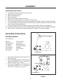
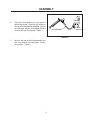
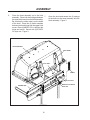
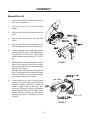
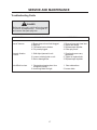
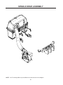
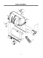
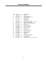
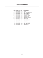
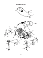
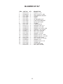
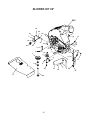
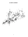
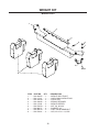
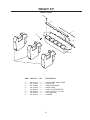
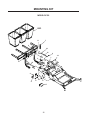
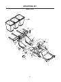
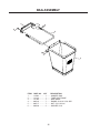
1
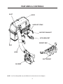
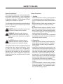
Collection System
Operators Manual
Parts Manual
Models: 114863 - DCK3
Please read these instructions carefully and make
sure you understand them before using the machine.
MANUAL NO. 539 114865 REV IR (01/30/07)
114873 - DCG3
2
©2007 Dixon. All Rights Reserved.
Beatrice, NE. Printed in U.S.A.
3
INDEX
Operators Guide
Features and Controls .............................................................. 4
General Information ................................................................. 5
Safety Procedures .................................................................... 5
Unpacking Instructions ............................................................. 7
Assembly Instructions .............................................................. 7
Collection System .............................................................. 7
Blower/Drive Kit ............................................................... 11
Operating the Collection System ........................................ 13
Maintenance and Service Instructions
Transport ................................................................................ 14
Cleaning and Washing ........................................................... 14
Storage ................................................................................... 14
Preventative Maintenance Schedule ...................................... 14
Caring for Vacuum Hoses ...................................................... 15
Cleaning Poly Mesh ............................................................... 15
Caring for Bags ...................................................................... 15
Troubleshooting Guide ........................................................... 16
Replacement Parts
Hood Assembly ...................................................................... 20
Hitch Assembly ....................................................................... 22
Blower Kit 52” ......................................................................... 24
Blower Kit 60” ......................................................................... 26
Blower Assembly .................................................................... 28
Weight Kit (Model DCG3) ....................................................... 30
Weight Kit (Model DCK3) ....................................................... 31
Mounting Kit (Model DCG3) ................................................... 32
Mounting Kit (Model DCK3) ................................................... 34
Bag Assembly ........................................................................ 36
WARNING: Engine exhaust, some of its constituents, and certain vehicle components contain or emit chemicals known to the State of California to cause cancer and birth defects or
other reproductive harm.
4
FEATURES & CONTROLS
INLET
HOOD
SUPPORT STRAP
SUPPORT BRACKET
HITCH BRACKET
WEIGHT BAR
BAG
HOSE
CAST WEIGHT
BLOWER
NOTE: Your Front Weight Bar may look different from those shown in this diagram.
5
SAFETY RULES
Safety Procedures
General Information
This manual will assist you in the safe operation
and proper maintenance of your Husqvarna
equipment. Read it thoroughly before attempting
to operate the machine. Call your dealer or Dixon
if additional information is required.
1 - Training:
• Read the Operator’s manual. If the operator(s)
or mechanic(s) can not read English it is the
owner’s responsibility to explain this material to
them.
• Become familiar with the safe operation of the
equipment, operator’s controls, and safety
signs.
• All operators and mechanics should be trained.
The owner is responsible for training the users.
• Never let children or untrained people operate
or service the equipment. Local regulations may
restrict the age of the operator.
• The owner/user can prevent and is responsible
for accidents or injuries occurring to themselves,
other people, and/or property.
The following safety symbols are used throughout
the manual to alert you to information about unsafe
actions or situations:
DANGER indicates immediate hazards that
may result in severe injury or death.
WARNING indicates unsafe actions or
situations that may cause severe injury,
death, and/or major equipment or property
damage.
2 - Preparation:
• Wear appropriate clothing including hard hat,
safety glasses and ear protection. Long hair,
loose clothing or jewelry may get tangled in
moving parts.
• Inspect the area where the equipment is to be
used and remove all objects such as rocks, toys
and wire which can be thrown by the machine.
• Use extra care when handling gasoline and
other fuels. They are flammable and vapors
are explosive. Use only an approved container.
Never remove gas cap or add fuel with engine
running. Allow engine to cool before refueling.
Do not smoke while fueling or operating
equipment. Never refuel or drain the machine
indoors.
• Check that operator’s controls, safety switches,
hoses, and shields are securely attached and
functioning properly. Do not operate unless
they are functioning properly.
CAUTION indicates unsafe actions or
situations that may cause injury and/or
minor equipment or property damage.
This equipment should not be modified without the
manufacturer’s prior written authorization. Doing
so may not only affect the equipments’
performance and durability, but also create safety
hazards for the operator and the surroundings.
Warranty will be void if changes are made to the
equipment without the manufacturer’s prior written
authorization.
6
SAFETY RULES
3 - Operation
• Never run an engine in an enclosed area.
• Only operate in good light, keeping away from
holes and hidden hazards.
• Slow down and use extra care on hillsides.
Make turns gradually and at slow speed. Do
not operate across the sides of slopes. Operate
up and down slopes only. Do not operate on
steep slopes.
• Turf conditions can affect the machine’s stability.
Do not operate on wet grass where traction may
be reduced.
• Do not change the engine governor setting or
overspeed the engine.
• Stop equipment and inspect vacuum impeller
and hoses after striking objects or if an abnormal
vibration occurs. Make necessary repairs before
resuming operations.
• Look behind and down before backing up to
ensure a clear path.
• Slow down and use caution when making turns
and crossing roads and sidewalks. Stop vacuum
and mower blades if not mowing.
• Do not operate machine under the influence of
alcohol or drugs.
• Use care when loading or unloading the machine
into a trailer or truck.
• Use care when approaching blind corners,
shrubs, trees, or other objects that may obscure
vision.
4 - Maintenance and Storage:
• Stop engine and disconnect spark plug wire.
Wait for all movement to stop before adjusting,
cleaning, or repairing.
• Clean grass and debris from muffler and engine
to help prevent fires. Clean up oil or fuel
spillage.
• Let engine cool before storing and do not store
near sparks or open flame.
• Shut off fuel while storing. Do not store fuel
near flames or drain indoors.
• Never allow untrained personnel to service
machine.
• Keep hands and feet away from moving parts.
If possible, do not make adjustments with the
engine running.
• Keep all parts in good working condition and all
hardware tightened. Replace all worn or
damaged decals.
7
ASSEMBLY
Unpacking Instructions
1.
2.
3.
4.
5.
6.
7.
8.
Cut plastic tie securing the hitch to the crate top.
Remove the top of the crate.
Remove the plastic bag.
Remove the hose.
Remove the sides and ends of the crate.
Remove the mounting kit box from the corner of the crate.
Cut the two plastic ties that secure the hitch assembly to the pallet. Remove the hitch assembly.
Cut the two plastic ties that secure the back of the hood, and the two that secure the front of the
hood. Remove the hood assembly.
9. Cut and two plastic ties that secure the weight bar to the pallet. Remove the weight bar.
10. Cut the two plastic ties that secure the blower assembly to the pallet. Remove the blower assembly.
11. Remove the 1 x 4 that secures the cast weights to the pallet. Remove the weights.
SUPPORT BRACKET
Assembly Instructions
Collection System
Tools Required:
Ratchet
Torque Wrench
1/2" Wrench
1/2" Socket
9/16" Wrench
9/16" Socket
5/8" Socket
(2) 3/4" Wrench
3/4" Socket
Flat Screw Driver
5/32" Allen Wrench
Hacksaw
11/32" Drill Bit
Drill
HITCH BRACKET
1.
2.
3.
Open the mounting kit box and remove all of
the components.
Place the support bracket on the frame and
secure with (2) 990563, 3/8 x 1 bolts and (2)
976979, 3/8 nyloc nuts. Figure 1.
Place the hitch brackets on the frame and
secure with (3) 990622, 1/2 x 1 1/4 bolts and
(3) 101331, 1/2 nyloc nuts. Figure 1.
SUPPORT BRACKET
HITCH BRACKET
FIGURE 1
8
ASSEMBLY
LANYARD
4.
Place the hitch assembly on the ground
behind the mower. Place the (2) hitch pins
thru the hitch and the hitch brackets. Secure
the hitch pins with the (2) hairpins that are
secured with the (2) lanyards. Figure 3.
HITCH ASSEMBLY
FIGURE 2
5.
Move to the rear of the hitch assembly and
pick it up towards the rear guard. Secure
using straps. Figure 2.
9
HITCH PIN
ASSEMBLY
6.
Place the hood assembly on to the hitch 7.
assembly. Place both hood hinges between
the upper hitch mounts on the hitch assembly.
Be sure that the rubber seal is on the inside
of the hood. Place the (2) friction washers
between the hood hinge and the upper hitch
mount. Place (2)990563, 3/8 x 1 bolt thru the
hinge and mount. Secure with (2) 976979,
3/8 nyloc nut. Figure 3.
Open the hood and secure the (2) springs
to the bolts on the hood assembly and the
hitch assembly. Figure 3.
HOOD ASSEMBLY
HOOD HINGE
3/8 X 1 BOLT
SPRING
3/8 NYLOC NUT
UPPER HITCH MOUNT
RUBBER SEAL
HITCH PIN
FIGURE 3
10
ASSEMBLY
HOOD ASSEMBLY
8.
9.
With the hood open, secure the (3) bags in
place. The back of the bags will hook over
the mounting tabs on the hitch assembly.
Figure 4.
Close the hood, and latch the draw latch over
the draw latch keeper on the hitch assembly.
Figure 4.
DRAW
LATCH
MOUNT
TABS
DRAW LATCH
KEEPER
BAG
FIGURE 4
10.
Install the (2) straps to the (2) support
brackets on hitch assembly and the (2)
support brackets on the frame. Figure 5.
SUPPORT BRACKET
STRAP
LANYARD
SUPPORT BRACKET
FIGURE 5
11
ASSEMBLY
Blower/Drive Kit
1.
Open the blower/drive kit box and remove
all of the components.
2.
Place the deck in the lowest cutting
height.
3.
Remove the right side belt shield from the
deck.
4.
Remove the deck belt from the right side
pulley.
5.
Remove the deck pulley and spindle, but
keep the hardware at hand for re-installation.
6.
Install new spindle. Use existing deck pulley
and key. Add new pulley, with raised portion
of pulley hub on the bottom. Secure with
existing hardware and tighten to 70 - 80 ft./
lbs.
7.
Attach blower housing assembly to mower
deck. First, insert the stud at rear of blower
housing into tube at rear of deck discharge
opening. See Figure 7.
Rotate blower housing around toward the
front. The eyelbolt at front of blower housing
will nest into slot in deck bracket. Tighten
with knob on eyeblot. See Figure 7.
8.
Install blower drive belt so that blower
rotation is clockwise when viewed from the
operator’s position. Belt will be easiest to
install if it goes on the flat idler pulley last.
Pull lever in Figure 8 to assist in routing belt
around flat idler. After belt is installed, make
certain the bolts are tight on the bracket
supporting the rear “V” idler pulley. Refer to
Figure 8.
FIGURE 7
FIGURE 8
12
ASSEMBLY
9.
Install belt guard to blower assembly using
three 1/4” washers and three 1/4” wing nuts.
See Figure 9.
10.
Install hose on the blower housing and
secure with hose clamp.
WING NUT
WASHER
BELT GUARD
FIGURE 9
13
OPERATION
Operating the Collection System
1.
NEVER USE THE COLLECTION SYSTEM
WITHOUT THE BLOWER ASSEMBLY
AND HOSES SECURELY ATTACHED.
2.
Make sure hoses are connected at both
ends. Inspect hoses prior to each use.
3.
Do not use the unit on slopes greater than
10 degrees.
4.
The mower must be running in order to
vacuum debris through the mower deck.
5.
In heavy grass it may be necessary to mow
and collect at a slower ground speed.
6.
Never attempt to unclog the collection system until the mower’s engine engine has
been shut off and all moving parts have come
to a complete stop.
7.
Do not stand behind the vent at the rear of
the collection system due to the potential for
small pieces of blowing debris to escape
through the vent.
8.
Wear eye and ear protection.
14
SERVICE AND MAINTENANCE
Transport
For best results, clean poly mesh inside hood regularly. Instructions for doing this can be found in
the Service section of this manual.
WARNING
The collection system bags must be completely empty or removed while driving forward onto a trailer. If the mower must be
loaded onto a trailer while there is still debris in the container, the mower must be
backed up onto the trailer to avoid tipping.
Cleaning and Washing
Storage
Regular cleaning, washing, and lubricating will
prolong the service of the machine.
1. Clean machine.
NOTE: Use care with power washers to avoid
damage to decals. Limit direct spray on these
items.
DO NOT EXCEED 1000 PSI WATER PRESSURE
FOR CLEANING.
2. Cover all scratches with touch-up paint.
3. Covered or indoor storage is recommended.
Preventative Maintenance Schedule
Item
Before
Each Use
Inspect/Clean Poly Mesh
X
Check/Tighten Nuts & Bolts
X
Check/Tighten Hoses
X
Every
5 Hours
Every
25 Hours
Every
50 Hours
X
Turn Hose End to End
X
Rotate Hose
X
Clean Machine
X
Inspect Bags
X
15
SERVICE AND MAINTENANCE
Caring For Hoses
Caring For Bags
1. Inspect hoses before each use. If hoses have
excessive wear, tears, or punctures, replace
immediately.
2. To prolong the life of the hose, periodically rotate hose and turn hose end to end. Refer to
Preventative Maintenance Schedule in this
manual.
3. Avoid twists and sharp turns in the hoses, as
they will increase wear on the hoses.
4. Avoid dragging the lower hose along the sides
of buildings or other hard surfaces.
Inspect the bags before each use. If bags have
excessive wear, tears or punctures, replace immediately.
Cleaning Instructions
NOTE: Under normal usage the bag material is
subject to deterioration and wear.
Cleaning Poly Mesh
The poly mesh on the collection system is located
inside the container hood. For best results, clean
poly mesh regularly.
Cleaning Instructions
1. Shut off engine.
2. Release the two (2) rubber latches under the
rear of the hood. Open hood and brush debris
off of both sides.
3. Close hood and re-latch.
DO NOT USE THE COLLECTION SYSTEM
WITHOUT POLY MESH SECURELY IN PLACE.
16
SERVICE AND MAINTENANCE
Troubleshooting Guide
DANGER
Before servicing unit, wait for all moving parts
to come to a complete stop. Turn engine off
and remove the spark plug wire.
PROBLEM
POSSIBLE CAUSE
CORRECTION
Loss of Vacuum.
1. Blower, hose or hood inlet clogged.
2. Bags full.
3. Fan blades bent or broken.
4. Poly mesh plugged.
1. Remove hose and clean inlet.
2. Inspect and empty.
3. Replace/repair impeller.
4. Clean poly mesh.
Unusual vibration
or noise.
1. Solid object jammed in unit.
1. Check and remove any
obstruction.
2. Tighten or replace bolts.
3. Replace/repair impleller.
2. Loose or missing bolts on unit.
3. Bent or damaged fan.
Unit difficult to close.
1. Obstructions keeping door from
completely closing.
2. Hood hinge bolts too tight.
17
1. Clear obstructions.
2. Loosen bolts.
SPINDLE DRIVE ASSEMBLY
NOTE: Your Front Weight Bar may look different from those shown in this diagram.
18
PARTS
ILLUSTRATIONS
19
HOOD ASSEMBLY
14
18
1
14
15
4
24
19
13
23
5
17
23
23
5
22
9
6
16
23
7
20
20
11
3
10
10
12
2
8
20
21
19
HOOD ASSEMBLY
ITEM PART NO. QTY
DESCRIPTION
1 ......... 539 111172 ...... 1 .......... HOOD
2 ......... 539 111174 ...... 1 .......... HOOD SUPPORT
3 ......... 539 111175 ...... 2 .......... SUPPORT, DRAW LATCH
4 ......... 539 111177 ...... 2 .......... HOOD HINGE
5 ......... 539 111181 ...... 2 .......... MOUNT PLATE
6 ......... 539 111182 ...... 1 .......... INLET TUBE
7 ......... 539 111260 ...... 1 .......... DECAL, VENTILATION
8 ......... 539 200478 ..... 2 .......... DRAW LATCH, FLEXIBLE T-HANDLE
9 ......... 539 111183 ...... 1 .......... MESH, POLY DIAMOND
10 ....... 539 111186 ...... 6 .......... SCREW, #10-24 X 1 1/8, MACH.
11 ....... 539 105408 ..... 21 ........ WASHER, #10
12 ....... 539 976977 ..... 6 .......... NUT, #10-24, NYLOC
13 ....... 539 976978 ..... 8 .......... NUT, 1/4C, NYLOC
14 ....... 539 976979 ..... 8 .......... NUT, 3/8C, NYLOC
15 ....... 539 990613 ..... 2 .......... NUT, 3/8C
16 ....... 539 991003 ..... 8 .......... HCS, 1/4-20 X 1 3/4
17 ....... 539 990645 ..... 6 .......... RHSNB, 3/8-16 X 1
18 ....... 539 990730 ..... 2 .......... HCS, 3/8-16 X 1 3/4
19 ....... 539 990598 ..... 16 ........ WASHER, 1/4
20 ....... 539 102744 ..... 11 ........ RIVET, 3/16 X 1/4
21 ....... 539 115392 ...... 1 .......... HOSE, 60”
22 ....... 539 111339 ...... 1 .......... HOOD SUPPORT, REAR
23 ....... 539 200684 ..... 30 ........ RIVET, 1/4 STAVEX
24 ....... 539 110033 ...... 8 .......... WASHER, #10
........... 539 115719 ...... 1 .......... HOSE CLAMP, DCK3 (NOT SHOWN)
21
HITCH ASSEMBLY
6
2
10
16
11
7
3
11
5
15
14
15
9
15
8
4
11
13
15
13
11
12
15
1
22
HITCH ASSEMBLY
ITEM PART NO. QTY
DESCRIPTION
1 ......... 539 111155 ...... 1 .......... HITCH
2 ......... 539 111187 ...... 4 .......... NUT, 1/2-13, WHIZLOCK
3 ......... 539 990625 ..... 4 .......... NUT, 1/2, JAM
4 ......... 539 111157 ...... 1 .......... MOUNT Z BRACE
5 ......... 539 111167 ...... 1 .......... SEAL, RUBBER
6 ......... 539 111158 ...... 2 .......... SUPPORT, OUTER
7 ......... 539 111162 ...... 2 .......... SUPPORT ARM
8 ......... 539 111267 ...... 2 .......... BRACKET, SUPPORT
9 ......... 539 111171 ...... 1 .......... SEAL STRAP
10 ....... 539 990580 ..... 3 .......... HCS, 1/4-20 X 3/4
11 ....... 539 990563 ..... 20 ........ HCS, 3/8-16 X 1
12 ....... 539 990655 ..... 2 .......... HCS, 3/8-16 X 1 1/2
13 ....... 539 990613 ..... 2 .......... NUT, 3/8C
14 ....... 539 976978 ..... 3 .......... NUT, 1/4C, NYLOC
15 ....... 539 976979 ..... 22 ........ NUT, 3/8C, NYLOC
16 ....... 539 990254 ..... 4 .......... WASHER, 1/2
23
BLOWER KIT 52”
14
17
4
REF.
21
22
2
23
18
12
15
24
5
15
25
15
20
13
15
12
11
6
1
16
16
8
3
12
10
15
7
11
9
19
24
BLOWER KIT 52”
ITEM PART NO. QTY
DESCRIPTION
1 ......... 539 121215 ..... 1 .......... PULLEY, “v”, 4.0”
2 ......... 539 990209 ..... 2 .......... HCS, 5/16-18 X 1, GR5
3 ......... 539 119489 ...... 2 .......... HUB, BEARING, SPACER
4 ......... 539 114993 ...... 1 .......... GUARD
5 ......... 539 118257 ...... 1 .......... ANGLE
6 ......... 539 118250 ...... 1 .......... 52” BLOWER PIVOT
7 ......... 539 118249 ...... 1 .......... FIXED IDLER BRACKET
8 ......... 539 117938 ...... 1 .......... BLOCK OFF PLATE
9 ......... 539 117912 ...... 1 .......... SPINDLE
10 ....... 539 117501 ...... 1 .......... 3” METAL IDLER
11 ....... 539 107271 ..... 4 .......... RHSSNB, 5/16C X 1.0
12 ....... 539 990188 ..... 6 .......... WASHER, 5/16, SAE
13 ....... 539 990316 ..... 2 .......... RHSNB, 5/16-18 X 3/4, GR5
14 ....... 539 990997 ..... 3 .......... WINGNUT, 1/4C, NYLOC
15 ....... 539 990717 ..... 9 .......... NUT, 5/16-18, NYLOC
16 ....... 539 976979 ..... 5 .......... NUT, 3/8-16, NYLOC
17 ....... 539 115562 ...... 3 .......... WASHER, 1/4, SAE
18 ....... 539 990645 ..... 4 .......... RHSNB, 3/8-16 X 1, GR5
19 ....... 539 109345 ..... 1 .......... RHSNB, 3/8-16 X 1 1/2, GR5
20 ....... 539 115746 ...... 1 .......... SEAT ADJUST KNOB
21 ....... 539 990627 ..... 1 .......... HCS, 5/16-18 X 1 1/4, GR5
22 ....... 539 990692 ..... 1 .......... WASHER, 5/16
23 ....... 539 115574 ...... 1 .......... EYE BOLT, 5/16 X 3 1/2
24 ....... 539 127092 ..... 1 .......... SPRING CAP
25 ....... 539 117939 ...... 1 .......... LATCH RECEIVER
........... 539 120772 ..... 1 .......... BELT (NOT SHOWN)
25
BLOWER KIT 60”
REF.
25
24
19
9
22
7
13
12
18
21
23
10
10
10
7
3
8
10
1
11
6
8
5
15
4
11
2
6
14
17
20
26
7
16
10
26
27
BLOWER KIT 60”
ITEM PART NO. QTY
DESCRIPTION
1 ......... 539 121215 ..... 1 .......... PULLEY, “v”, 4.0”
2 ......... 539 119489 ...... 2 .......... HUB, BEARING, SPACER
3 ......... 539 118257 ...... 1 .......... ANGLE
4 ......... 539 118249 ...... 1 .......... FIXED IDLER BRACKET
5 ......... 539 117501 ...... 1 .......... 3” METAL IDLER
6 ......... 539 107271 ..... 4 .......... RHSSNB, 5/16C X 1.0
7 ......... 539 990188 ..... 6 .......... WASHER, 5/16, SAE
8 ......... 539 990316 ..... 2 .......... RHSNB, 5/16-18 X 3/4, GR5
9 ......... 539 990997 ..... 3 .......... WINGNUT, 1/4C, NYLOC
10 ....... 539 990717 ..... 9 .......... NUT, 5/16-18, NYLOC
11 ....... 539 976979 ..... 5 .......... NUT, 3/8-16, NYLOC
12 ....... 539 115562 ...... 3 .......... WASHER, 1/4, SAE
13 ....... 539 990645 ..... 4 .......... RHSNB, 3/8-16 X 1, GR5
14 ....... 539 109345 ..... 1 .......... RHSNB, 3/8-16 X 1 1/2, GR5
15 ....... 539 118261 ...... 1 .......... 60” BLOWER PIVOT
16 ....... 539 118265 ...... 1 .......... BLOCK OFF PLATE
17 ....... 539 130198 ..... 1 .......... GUARD
18 ....... 539 117939 ...... 1 .......... LATCH RECEIVER
19 ....... 539 990209 ..... 2 .......... HCS, 5/16-18 X 1, GR5
20 ....... 539 117912 ...... 1 .......... SPINDLE
21 ....... 539 127092 ..... 1 .......... SPRING CAP
22 ....... 539 115574 ...... 1 .......... EYE BOLT, 5/16 X 3 1/2
23 ....... 539 115746 ...... 1 .......... SEAT ADJUST KNOB
24 ....... 539 990692 ..... 1 .......... WASHER, 5/16
25 ....... 539 990627 ..... 1 .......... HCS, 5/16-18 X 1 1/4, GR5
26 ....... 539 121859 ..... 1 .......... SPRING MOUNT
27 ....... 539 115674 ...... 1 .......... L-NUT, 5/16-18, FLANGED
........... 539 120772 ..... 1 .......... BELT (NOT SHOWN)
27
BLOWER ASSEMBLY
18
10
8
4
25
2
24
26
21
27
12
29
25
25
13
14
29
11
29
17
6
24
3
28
15 13
16
1
30
32
31
19
20
30
9
5
23
22
28
7
BLOWER ASSEMBLY
ITEM PART NO. QTY
DESCRIPTION
1 ......... 539 117919 ...... 1 .......... FAN HOUSING
2 ......... 539 118255 ...... 1 .......... SANDLINER
3 ......... 539 118253 ...... 1 .......... BLOWER HUB STIFFENER
4 ......... 539 117917 ...... 1 .......... FAN
5 ......... 539 117924 ...... 1 .......... FAN IDLER ARM
6 ......... 539 117500 ...... 1 .......... 3” METAL IDLER
7 ......... 539 118211 ...... 1 .......... BLOWER EXIT TUBE
8 ......... 539 118270 ...... 1 .......... OUTER PLATE
9 ......... 539 115275 ...... 1 .......... SPRING, 4”
10 ....... 539 119902 ...... 1 .......... DECAL, LOGO
11 ....... 539 117970 ...... 1 .......... DECK HUB
12 ....... 539 115638 ...... 1 .......... ZERK, 3/15” DRIVE
13 ....... 539 119260 ...... 2 .......... BEARING
14 ....... 539 117971 ...... 1 .......... SPACER
15 ....... 539 115326 ...... 1 .......... HUB PULLEY SPACER
16 ....... 539 119811 ...... 1 .......... TRASH GUARD
17 ....... 539 119264 ...... 1 .......... PULLEY
18 ....... 539 115401 ...... 1 .......... DECAL, G.C. WARNING
19 ....... 539 115636 ...... 1 .......... WASHER, 1/2
20 ....... 539 115387 ...... 1 .......... KEY, 1/4 X .88
21 ....... 539 990655 ..... 4 .......... HCS, 3/8-16 X 1 1/2, GR5
22 ....... 539 990730 ..... 1 .......... HCS, 3/8-16 X 1 3/4, GR5
23 ....... 539 115511 ...... 1 .......... BOLT, 1/2-20 X 1 1/4
24 ....... 539 124796 ..... 7 .......... HCS, 5/16-18 X 1/2, GR5
25 ....... 539 115674 ...... 11 ........ L-NUT, 5/16-18, FLANGED
26 ....... 539 990316 ..... 10 ........ RHSNB, 5/16-18 X 3/4, GR5
27 ....... 539 107271 ..... 1 .......... RHSSNB, 5/16C X 1.0
28 ....... 539 990645 ..... 2 .......... RHSNB, 3/8-16 X 1, GR5
29 ....... 539 976979 ..... 7 .......... NUT, 3/8-16, NYLOC
30 ....... 539 990188 ..... 7 .......... WASHER, 5/16, SAE
31 ....... 539 990122 ..... 3 .......... WASHER, 3/8, SAE
32 ....... 539 990250 ..... 1 .......... WASHER, 1/2, SAE
29
WEIGHT KIT
MODEL DCG3
1
2
3
4
6
7
5
9
8
ITEM PART NO. QTY
DESCRIPTION
1 ......... 539 020255 ..... 1 .......... WEIGHT BAR, FRONT
2 ......... 539 111313 ...... 1 .......... HOLD DOWN, WEIGHT BAR
3 ......... 539 102049 ..... 2 .......... CLEVIS PIN
4 ......... 539 108096 ..... 2 .......... SPRING RETAINER
5 ......... 539 111259 ...... 2 .......... WEIGHT KEEPER
6 ......... 539 976979 ..... 4 .......... NUT, 3/8, NYLOC
7 ......... 539 990517 ..... 4 .......... WASHER, 3/8
8 ......... 539 000019 ..... 3 .......... CAST COUNTERWEIGHT
9 ......... 539 976941 ..... 4 .......... HCS, 3/8-16 X 1 1/4, GR5
30
WEIGHT KIT
MODEL DCK3
2
1
7
3
8
6
4
5
ITEM
PART NO.
1 ......... 539
2 ......... 539
3 ......... 539
4 ......... 539
5 ......... 539
6 ......... 539
7 ......... 539
8 ......... 539
QTY
DESCRIPTION
111313 ...... 1 .......... HOLD DOWN, WEIGHT BAR
102049 ..... 2 .......... CLEVIS PIN
108096 ..... 2 .......... SPRING RETAINER
114858 ...... 1 .......... WEIGHT BAR
000019 ..... 3 .......... CAST COUNTERWEIGHT
990627 ..... 4 .......... HCS, 5/16-18 X 1 1/4, GR5
977778 ..... 1 .......... PAD, ABRASIVE
102587 ..... 3 .......... BUMPER
31
MOUNTING KIT
MODEL DCG3
REF.
11
9
7
8
16
12
15
4
10
1
3
2
13 5
12
16
11
5
6
4
3
2
6
14
6
5
17
32
MOUNTING KIT
MODEL DCG3
ITEM PART NO. QTY
DESCRIPTION
1 ......... 539 111215 ...... 2 .......... SUPPORT BRACKET
2 ......... 539 111206 ...... 2 .......... HITCH PIN
3 ......... 539 111192 ...... 2 .......... HAIRPIN
4 ......... 539 102563 ..... 2 .......... LANYARD
5 ......... 539 101331 ..... 8 .......... NUT, 1/2, NYLOC
6 ......... 539 990622 ..... 8 .......... BOLT, 1/2-13 X 1 1/4, WHIZLK
7 ......... 539 111191 ...... 2 .......... SPRING
8 ......... 539 102998 ..... 2 .......... FRICTION WASHER
9 ......... 539 976941 ..... 2 .......... HCS, 3/8-16 X 1 1/4, GR5
10 ....... 539 990563 ..... 4 .......... HCS, 3/8-16 X 1, GR5
11 ....... 539 976979 ..... 6 .......... NUT, 3/8-16, NYLOC
12 ....... 539 114674 ...... 2 .......... STRAP
13 ....... 539 111199 ...... 1 .......... HITCH BRACKET, LEFT
14 ....... 539 111201 ...... 1 .......... HITCH BRACKET, RIGHT
15 ....... 539 990646 ..... 2 .......... HCS, 1/2-13 X 1, GR5
16 ....... 539 115609 ...... 2 .......... NUT, 1/2-13, THIN NYLOC
17 ....... 539 115719 ...... 1 .......... HOSE CLAMP
33
MOUNTING KIT
MODEL DCK3
REF.
14
12
10
11
7
6
3
15
5
14
6
9
5
13
2
7
16
4
1
8
4
9
13
3
8
17
34
MOUNTING KIT
MODEL DCK3
ITEM PART NO. QTY
DESCRIPTION
1 ......... 539 111205 ...... 1 .......... HITCH BRACKET, RIGHT
2 ......... 539 111203 ...... 1 .......... HITCH BRACKET, LEFT
3 ......... 539 111215 ...... 2 .......... SUPPORT BRACKET
4 ......... 539 111206 ...... 2 .......... HITCH PIN
5 ......... 539 111192 ...... 2 .......... HAIRPIN
6 ......... 539 102563 ..... 2 .......... LANYARD
7 ......... 539 114672 ...... 2 .......... STRAP
8 ......... 539 101331 ..... 8 .......... NUT, 1/2, NYLOC
9 ......... 539 990622 ..... 8 .......... BOLT, 1/2-13 X 1 1/4, WHIZLK
10 ....... 539 111191 ...... 2 .......... SPRING
11 ....... 539 102998 ..... 2 .......... FRICTION WASHER
12 ....... 539 976941 ..... 2 .......... HCS, 3/8-16 X 1 1/4, GR5
13 ....... 539 990563 ..... 4 .......... HCS, 3/8-16 X 1, GR5
14 ....... 539 976979 ..... 6 .......... NUT, 3/8-16, NYLOC
15 ....... 539 990646 ..... 2 .......... HCS, 1/2-13 X 1, GR5
16 ....... 539 115609 ...... 2 .......... NUT, 1/2-13, THIN, NYLOC
17 ....... 539 115719 ...... 1 .......... HOSE CLAMP
35
BAG ASSEMBLY
1
5
4
4
2
6
5
3
ITEM PART NO. QTY
DESCRIPTION
1 ......... 110063 ............. 1 .......... HANGER, BAG
2 ......... 111166 ............. 1 .......... TUBE, BAG FRAME
3 ......... 111300 ............. 1 .......... BAG, SMALL
4 ......... 990316 ............ 7 .......... RHSNB, 5/16-18 X 5/8, GR5
5 ......... 990717 ............ 7 .......... NUT, 5/16, NYLOC
6 ......... 990692 ............ 3 .......... WASHER, 5/16
36