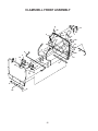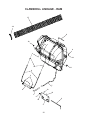
1
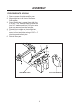
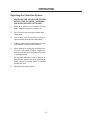
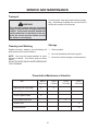
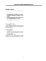
Collection System
Operators Manual
Parts Manual
Models: 130211 - DCKC
Please read these instructions carefully and make
sure you understand them before using the machine.
MANUAL NO. 539 130679 REV IR (02/06/07)
130212 - DCRC
2
©2007 Dixon. All Rights Reserved.
Beatrice, NE. Printed in U.S.A.
3
INDEX
Operators Guide
General Information ................................................................. 5
Safety Procedures .................................................................... 5
Assembly Instructions .............................................................. 7
Operating the Collection System ........................................ 13
Maintenance and Service Instructions
Transport ................................................................................ 14
Cleaning and Washing ........................................................... 14
Storage ................................................................................... 14
Preventative Maintenance Schedule ...................................... 14
Caring for Vacuum Hoses ...................................................... 15
Cleaning Poly Mesh ............................................................... 15
Troubleshooting Guide ........................................................... 16
Replacement Parts
Clamshell Assembly ............................................................... 18
Clamshell Rear Assembly ...................................................... 20
Clamshell Front Assembly ...................................................... 22
Clamshell Linkage - Ram ....................................................... 24
Clamshell Linkage - Kodiak .................................................... 26
Weight Kit Ram ...................................................................... 28
Weight Kit Kodaik ................................................................... 30
WARNING: Engine exhaust, some of its constituents, and certain vehicle components contain or emit chemicals known to the State of California to cause cancer and birth defects or
other reproductive harm.
4
SAFETY RULES
Safety Procedures
General Information
This manual will assist you in the safe operation
and proper maintenance of your Husqvarna 1 - Training:
equipment. Read it thoroughly before attempting • Read the Operator’s manual. If the operator(s)
or mechanic(s) can not read English it is the
to operate the machine. Call your dealer or Dixon
owner’s responsibility to explain this material to
if additional information is required.
them.
The following safety symbols are used throughout • Become familiar with the safe operation of the
equipment, operator’s controls, and safety
the manual to alert you to information about unsafe
signs.
actions or situations:
• All operators and mechanics should be trained.
The owner is responsible for training the users.
DANGER indicates immediate hazards that
• Never let children or untrained people operate
may result in severe injury or death.
or service the equipment. Local regulations may
restrict the age of the operator.
WARNING indicates unsafe actions or
• The owner/user can prevent and is responsible
situations that may cause severe injury,
for accidents or injuries occurring to themselves,
death, and/or major equipment or property
other people, and/or property.
damage.
2 - Preparation:
• Wear appropriate clothing including hard hat,
safety glasses and ear protection. Long hair,
loose clothing or jewelry may get tangled in
moving parts.
• Inspect the area where the equipment is to be
used and remove all objects such as rocks, toys
and wire which can be thrown by the machine.
• Use extra care when handling gasoline and
other fuels. They are flammable and vapors
are explosive. Use only an approved container.
Never remove gas cap or add fuel with engine
running. Allow engine to cool before refueling.
Do not smoke while fueling or operating
equipment. Never refuel or drain the machine
indoors.
• Check that operator’s controls, safety switches,
hoses, and shields are securely attached and
functioning properly. Do not operate unless
they are functioning properly.
CAUTION indicates unsafe actions or
situations that may cause injury and/or
minor equipment or property damage.
This equipment should not be modified without the
manufacturer’s prior written authorization. Doing
so may not only affect the equipments’
performance and durability, but also create safety
hazards for the operator and the surroundings.
Warranty will be void if changes are made to the
equipment without the manufacturer’s prior written
authorization.
5
SAFETY RULES
3 - Operation
• Never run an engine in an enclosed area.
• Only operate in good light, keeping away from
holes and hidden hazards.
• Slow down and use extra care on hillsides.
Make turns gradually and at slow speed. Do
not operate across the sides of slopes. Operate
up and down slopes only. Do not operate on
steep slopes.
• Turf conditions can affect the machine’s stability.
Do not operate on wet grass where traction may
be reduced.
• Do not change the engine governor setting or
overspeed the engine.
• Stop equipment and inspect vacuum impeller
and hoses after striking objects or if an abnormal
vibration occurs. Make necessary repairs before
resuming operations.
• Look behind and down before backing up to
ensure a clear path.
• Slow down and use caution when making turns
and crossing roads and sidewalks. Stop vacuum
and mower blades if not mowing.
• Do not operate machine under the influence of
alcohol or drugs.
• Use care when loading or unloading the machine
into a trailer or truck.
• Use care when approaching blind corners,
shrubs, trees, or other objects that may obscure
vision.
4 - Maintenance and Storage:
• Stop engine and disconnect spark plug wire.
Wait for all movement to stop before adjusting,
cleaning, or repairing.
• Clean grass and debris from muffler and engine
to help prevent fires. Clean up oil or fuel
spillage.
• Let engine cool before storing and do not store
near sparks or open flame.
• Shut off fuel while storing. Do not store fuel
near flames or drain indoors.
• Never allow untrained personnel to service
machine.
• Keep hands and feet away from moving parts.
If possible, do not make adjustments with the
engine running.
• Keep all parts in good working condition and all
hardware tightened. Replace all worn or
damaged decals.
6
ASSEMBLY
Assembly Instructions
Tools Required:
Ratchet
Torque Wrench
1/2" Wrench
1/2" Socket
9/16" Wrench
9/16" Socket
(2) 3/4" Wrench
3/4" Socket
Flat Screw Driver
(2) 1” Wrench - open end
RAM/RAM MAG
1.
Remove clamshell from crate.
2.
Remove two 5/16 x 3/4 carriage bolts from
the lower flange of the rear guard on the
mower.
3.
Place (539 114781) Mount Bracket, Lower
in place and secure using four (539 111785)
3/8 x 3/4 carriage bolts, four (539 976979) 3/
8 nyloc hex nut and two (539 107271) 5/16 x
1 carriage bolts. Reuse the two 5/16 nyloc
hex nuts previously removed from the 5/16 x
3/4 carriage bolts. See Figure 1.
REAR GUARD
LOWER FLANGE
539 114781 MOUNT BRACKET, LOWER
FIGURE 1
539 114786 PLATE,
SUPPORT, LINKAGE
4.
Lift seat and latch with seat latch.
5.
Remove seat springs.
6.
Place (539 114786) Plate, Support, Linkage
on frame.
Reposition springs and secure with (990209)
5/16 x 1 hex bolts and hex nut previously
removed from seat springs. See Figure 2.
7.
8.
Attach two (539 114783) Linkage, Support
to the clamshell assembly as shown in Figure 2.
9.
Secure with two (539 100476) 5/8 hex jam
nut and two (539 115591) 5/8 nyloc hex nut
as shown. Do not tighten nuts.
FIGURE 2
7
ASSEMBLY
10. Lift Clamshell assembly onto (539 114781)
Mount Bracket, Lower. Position tubes on
bottom of clamshell on out side of the tubes
on (539 114781) Mount Bracket, Lower.
539 114782
BRACKET
11. Secure with (539 119372) Hinge Pin and (539
115501) Cotter Pin.
12. Hook both (539 114783) Linkage, Support
into (539 114786) Plate, Support, Linkage
and secure with two remaining (539 115501)
Cotter Pins.
CLAMSHELL
ASSEMBLY
13. Tighten (539 100476) 5/8 Jam nut and (539
115591) 5/8 Nyloc nut so that the clamshell
is sitting straight on unit.
539 114812 LINKAGE,
SUPPORT
FIGURE 3
14. Tighten (539 114782) Brackets on front of
clamshell.
8
ASSEMBLY
KODIAK
1. Remove clamshell from crate.
2.
Remove two 5/16 x 3/4 carriage bolts from
the lower flange of the rear guard on the
mower.
3.
Place (539 114815) Mount Bracket, Lower
in place and secure using four (539 111785)
3/8 x 3/4 carriage bolts, four (539 976979) 3/
8 nyloc hex nut and two (539 107271) 5/16 x
1 carriage bolts. Reuse the two 5/16 nyloc
hex nuts previously removed from the 5/16 x
3/4 carriage bolts. See Figure 4.
REAR GUARD
LOWER FLANGE
539 114815 MOUNT BRACKET, LOWER
FIGURE 4
539 114811 BRACKET, SUPPORT
4.
Secure two (539 114811) Bracket, Support
to frame as shown in Figure 5. Secure using (539 103433) 1/2 x 3 1/4 hex bolt and
(539 101331) 1/2 hex nyloc nut.
FIGURE 5
FIGURE 3
9
ASSEMBLY
5.
Attach two (539 114812) Linkage, Support
to the clamshell assembly as shown in Figure 6.
6.
Secure with two (539 100476) 5/8 hex jam
nut and two (539 115591) 5/8 nyloc hex nut
as shown. Do not tighten nuts.
7.
8.
9.
539 114782
BRACKET
Lift Clamshell assembly onto (539 114815)
Mount Bracket, Lower. Position tubes on
bottom of clamshell on out side of the tubes
on (539 114781).
Secure with (539 119372) Hinge Pin and (539
115501) Cotter Pin.
Hook both (539 114812) Linkage, Support
into (539 114811) Bracket, Support and secure with two remaining (539 115501) Cotter Pins.
10. Tighten (539 100476) 5/8 Jam nut and
(115591) 5/8 Nyloc nut so that the clamshell
is sitting straight on unit.
11. Tighten (539 114782) Brackets on front of
clamshell.
10
CLAMSHELL
ASSEMBLY
539 114812 LINKAGE,
SUPPORT
FIGURE 6
ASSEMBLY
FRONT WEIGHTS - RAM
CAUTION
1.
2.
3.
Bolt cast weight and two weight brackets together using four bolts (539 106492, 3/8 x 2
3/4”) and four nuts (539 976979, 3/8” nyloc).
Slide both weight brackets over the front tube
on the frame. Be sure to position in the center of the frame.
Secure with four bolts (539 991126, 3/8 x 3
3/4”) and four nuts (539 976979, 3/8”
nyloc).
DO NOT operate mower with grass catcher,
unless the front weights are installed.
BRACKET
539 976979
539 991126
539 106492
CAST WEIGHT
539 976979
11
ASSEMBLY
FRONT WEIGHTS - KODIAK
1. Remove mower foot plate and floor pan.
2. Align weight bar to the front of the frame.
See diagram.
3. Secure weight bar to mower frame with four
5/16-18 x 1 1/4” hex bolts from kit, reuse the
four 5-16” washers and four 5/16” nyloc nuts
that were removed from the foot plate.
4. Place all front weights on front weight bar.
5. Place holddown bar over front weights and
secure to front weight bar using two 3/8” x 1”
clevis pins and two hair pins.
6. Reinstall floor pan.
WEIGHT BAR HOLD DOWN
CAST COUNTERWEIGHT
FRONT WEIGHT BAR
12
OPERATION
Operating the Collection System
1.
NEVER USE THE COLLECTION SYSTEM
WITHOUT THE BLOWER ASSEMBLY
AND HOSES SECURELY ATTACHED.
2.
Make sure hoses are connected at both
ends. Inspect hoses prior to each use.
3.
Do not use the unit on slopes greater than
10 degrees.
4.
The mower must be running in order to
vacuum debris through the mower deck.
5.
In heavy grass it may be necessary to mow
and collect at a slower ground speed.
6.
Never attempt to unclog the collection system until the mower’s engine engine has
been shut off and all moving parts have come
to a complete stop.
7.
Do not stand behind the vent at the rear of
the collection system due to the potential for
small pieces of blowing debris to escape
through the vent.
8.
Wear eye and ear protection.
13
SERVICE AND MAINTENANCE
Transport
For best results, clean poly mesh inside hood regularly. Instructions for doing this can be found in
the Service section of this manual.
WARNING
The collection system must be completely
empty or removed while driving forward onto
a trailer. If the mower must be loaded onto
a trailer while there is still debris in the container, the mower must be backed up onto
the trailer to avoid tipping.
Cleaning and Washing
Storage
Regular cleaning, washing, and lubricating will
prolong the service of the machine.
1. Clean machine.
NOTE: Use care with power washers to avoid
damage to decals. Limit direct spray on these
items.
DO NOT EXCEED 1000 PSI WATER PRESSURE
FOR CLEANING.
2. Cover all scratches with touch-up paint.
3. Covered or indoor storage is recommended.
Preventative Maintenance Schedule
Item
Before
Each Use
Inspect/Clean Poly Mesh
X
Check/Tighten Nuts & Bolts
X
Check/Tighten Hoses
X
Every
5 Hours
Every
25 Hours
Every
50 Hours
X
Turn Hose End to End
X
Rotate Hose
X
Clean Machine
X
14
SERVICE AND MAINTENANCE
Caring For Hoses
1. Inspect hoses before each use. If hoses have
excessive wear, tears, or punctures, replace
immediately.
2. To prolong the life of the hose, periodically rotate hose and turn hose end to end. Refer to
Preventative Maintenance Schedule in this
manual.
3. Avoid twists and sharp turns in the hoses, as
they will increase wear on the hoses.
4. Avoid dragging the lower hose along the sides
of buildings or other hard surfaces.
Cleaning Poly Mesh
The poly mesh on the collection system is located
inside the container hood. For best results, clean
poly mesh regularly.
Cleaning Instructions
1. Shut off engine.
2. Release the two (2) rubber latches under the
rear of the hood. Open hood and brush debris
off of both sides.
3. Close hood and re-latch.
DO NOT USE THE COLLECTION SYSTEM
WITHOUT POLY MESH SECURELY IN PLACE.
15
SERVICE AND MAINTENANCE
Troubleshooting Guide
DANGER
Before servicing unit, wait for all moving parts
to come to a complete stop. Turn engine off
and remove the spark plug wire.
PROBLEM
POSSIBLE CAUSE
CORRECTION
Loss of Vacuum.
1. Hose or hood inlet clogged.
2. Container full.
3. Poly mesh plugged.
1. Remove hose and clean inlet.
2. Inspect and empty.
3. Clean poly mesh.
Unusual vibration
or noise.
1. Solid object jammed in unit.
1. Check and remove any
obstruction.
2. Tighten or replace bolts.
2. Loose or missing bolts on unit.
Unit difficult to close.
1. Obstructions keeping door from
completely closing.
2. Hood hinge bolts too tight.
16
1. Clear obstructions.
2. Loosen bolts.
PARTS
ILLUSTRATIONS
17
CLAMSHELL ASSEMBLY
4
REF.
1
3
3
2
7
REF.
8
9
5
6
10
18
CLAMSHELL ASSEMBLY
ITEM
PART NO.
QTY.
DESCRIPTION
1 .. 539 990629 ... 2 ... HCS 3/8-16 X 2 1/4, GR5
2 .. 539 200282 ... 2 ... NUT, 3/8-16, HAM, NYLOC
3 .. 539 990122 ... 3 ... WASHER, 3/8, SAE
4 ... 539 115972 ... 2 ... BUSHING
5 .. 539 990717 ... 1 ... NUT, 5/16-18, NYLOC
6 ... 539 119414 ... 1 ... BUSHING, PLASTIC
7 ... 539 117244 ... 1 ... ROD END
8 ... 539 115609 ... 1 ... NUT, 1/2-13, THIN, NYLOC
9 .. 539 990625 ... 1 ... NUT, 1/2-13, JAM
10 ... 539 119371 ... 1 ... LIFT LINK
19
CLAMSHELL REAR ASSEMBLY
1
12
16
3
17 13
18 7
15
10
10
9
19
8
11
2
6
5
4
18
10
14
18
10
20
12
CLAMSHELL REAR ASSEMBLY
ITEM
PART NO.
QTY.
DESCRIPTION
1 ... 539 117967 ... 1 ... REAR FRAME
2 ... 539 119396 ... 2 ... STRAP
3 ... 539 119367 ... 1 ... HOOK LATCH
4 ... 539 119377 ... 1 ... CLAMSHELL BACK
5 ... 539 119458 ... 1 ... STRAP
6 ... 539 117543 ... 1 ... CHAMSHELL VENT
7 ... 539 115677 ... 2 ... CLIP NUT, 5/16-18
8 ... 539 119412 ... 1 ... VENT SCHREEN
9 ... 539 115789 ... 3 ... NYLON WASHER
10 .. 539 990188 . 17 ... WASHER, 5/16, SAE
11 .. 539 107271 ... 6 ... RHSSNB, 5/16C X 1.0
12 .. 539 100472 ... 7 ... RHSNB, 5/16-18 X 1 1/4, GR5
13 .. 539 990254 ... 1 ... LOCKWASHER, 1/2
14 .. 539 990316 ... 2 ... RHSNB, 5/16-18 X 3/4, GR5
15 .. 539 990206 ... 2 ... HCS, 5/16-18 X 3/4, GR5
16 ... 539 115609 ... 1 ... NUT, 1/2-13, THIN, NYLOC
17 .. 539 990625 ... 1 ... NUT, 1/2-13, JAM
18 .. 539 990717 . 15 ... NUT, 5/16-18, NYLOC
19 ... 539 119413 ... 6 ... LARGE DOME RIVET
21
CLAMSHELL FRONT ASSEMBLY
6
8
16
23
5
18
2
7
17
18
23
27
18
23
24
4
16
13
18
19
3
1
22
18
14
19
20
11
15
20
25
26
28
12
25
9
21
10
23
21
22
CLAMSHELL FRONT ASSEMBLY
ITEM
PART NO.
QTY.
DESCRIPTION
1 ... 539 119410 ... 1 ... FRONT FRAME
2 ... 539 119409 ... 2 ... STRAP
3 ... 539 119368 ... 2 ... STRAP
4 ... 539 117986 ... 1 ... LIFT SHAFT
5 ... 539 119376 ... 1 ... CLAMSHELL, FRONT
6 ... 539 115596 ... 2 ... CLEVIS PIN, 5/16
7 ... 539 115489 ... 2 ... RETAINING RING
8 ... 539 119433 ... 1 ... DEFLECTOR
9 ... 539 114779 ... 1 ... MOUNT, LOWER, CLAMSHELL
10 ... 539 119458 ... 1 ... STRAP
11 ... 539 121194 ... 1 ... CLAMSHELL SPACER
12 ... 539 114782 ... 2 ... BRACKET, SUPPORT
13 ... 539 115441 ... 1 ... WINDOW
14 ... 539 114785 ... 2 ... BRACKET, SUPPORT, UPPER
15 ... 539 117988 ... 2 ... SPACER PLATE
16 ... 539 115495 ... 4 ... WASHER, 11/32
17 ... 539 115560 . 10 ... WASHER
18 .. 539 990188 . 23 ... WASHER, 5/16, SAE
19 .. 539 107271 ... 6 ... RHSSNB, 5/16C X 1.0
20 .. 539 100472 ... 6 ... RHSNB, 5/16-18 X 1 1/4, GR5
21 .. 539 102933 ... 9 ... RHSNB, 5/16-18 X 1 1/2, GR5
22 .. 539 990316 ... 2 ... RHSNB, 5/16-18 X 3/4, GR5
23 .. 539 990717 . 23 ... NUT, 5/16-18, NYLOC
24 ... 539 115661 . 10 ... POP RIVE, 5/32
25 .. 539 990563 ... 4 ... HCS, 3/8-16 X 1, GR5
26 .. 539 990517 ... 2 ... WASHER, 3/8
27 ... 539 119413 ... 6 ... LARGE DOME RIVET
28 .. 539 976979 ... 4 ... NUT, 3/8-16, NYLOC
23
CLAMSHELL LINKAGE - RAM
17
18
8
10
9
10
12
11
4
5
16
7
6
13
15
1
5
2
14
3
24
CLAMSHELL LINKAGE - RAM
ITEM
PART NO.
QTY.
DESCRIPTION
1 ... 539 116443 ... 1 ... BAR SLEEVE
2 ... 539 119372 ... 1 ... HINGE PIN
3 ... 539 114781 ... 1 ... BRACKET, MOUNT, LOWER
4 ... 539 114783 ... 2 ... LINKAGE, SUPPORT
5 ... 539 115501 ... 3 ... HAIR PIN COTTER, 1/8 DIA. X 1 3/4
6 ... 539 114786 ... 1 ... BRACKET, SUPPORT, LINKAGE
7 ... 539 114824 ... 1 ... LINKAGE, ARM, DUMP
8 ... 539 114816 ... 1 ... LINKAGE, LATCH
9 .. 539 990188 ... 1 ... WASHER, 5/16, SAE
10 .. 539 990717 ... 3 ... NUT, 5/16-18, NYLOC
11 ... 539 110340 ... 1 ... NUT, 5/8-11C, NYLOC
12 .. 539 100476 ... 2 ... NUT, 5/8-11, JAM
13 ... 539 111785 ... 4 ... RHSNB, 3/8-16 X 3/4, GR5
14 .. 539 976979 ... 4 ... NUT, 3/8-16, NYLOC
15 .. 539 107271 ... 2 ... RHSSNB, 5/16C X 1
16 .. 539 990209 ... 3 ... HCS, 5/16-18 X 1, GR5
17 ... 539 115392 ... 1 ... FLEX HOSE - 60"
18 ... 539 115719 ... 1 ... HOSE CLAMP
25
CLAMSHELL LINKAGE - KODIAK
15
13
1
12
6
5
6
10
8
16
4
14
18
3
7
3
19
11
9
17
2
10
26
CLAMSHELL LINKAGE - KODIAK
ITEM
PART NO.
QTY.
DESCRIPTION
1 ... 539 116443 ... 1 ... BAR SLEEVE
2 ... 539 119372 ... 1 ... HINGE PIN
3 ... 539 115501 ... 3 ... HAIR PIN COTTER, 1/8 DIA. X 1 3/4
4 ... 539 114816 ... 1 ... LINKAGE, LATCH
5 .. 539 990188 ... 1 ... WASHER, 5/16, SAE
6 .. 539 990717 ... 3 ... NUT, 5/16-18, NYLOC
7 ... 539 110340 ... 1 ... NUT, 5/8-11C, NYLOC
8 .. 539 100476 ... 2 ... NUT, 5/8-11, JAM
9 ... 539 111785 ... 4 ... RHSNB, 3/8-16 X 3/4, GR5
10 .. 539 976979 ... 4 ... NUT, 3/8-16, NYLOC
11 .. 539 107271 ... 2 ... RHSSNB, 5/16C X 1
12 ... 539 115392 ... 1 ... FLEX HOSE - 60"
13 ... 539 115719 ... 1 ... HOSE CLAMP
14 ... 539 114811 ... 2 ... BRACKET, SUPPORT
15 ... 539 114813 ... 1 ... DUMP ARM, KODIAK
16 ... 539 114812 ... 2 ... LINKAGE SUPPORT
17 ... 539 114815 ... 1 ... PLATE MOUNT, SUPPORT
18 .. 539 101331 ... 2 ... NUT, 1/2, NYLOC
19 .. 539 103433 ... 2 ... HCS, 1/2-13 X 3 1/4, GR5
27
WEIGHT KIT - RAM
4
5
3
4
2
1
5
ITEM
PART NO.
QTY.
DESCRIPTION
1 ... 539 111587 ... 1 ... CAST WEIGHT
2 ... 539 114898 ... 2 ... BRACKET, WEIGHT
3 .. 539 106492 ... 4 ... HCS, 3/8-16 X 2 3/4, GR5
4 ... 539 991126 ... 4 ... HCS, 3/8-16 X 3 3/4, GR5
5 .. 539 976979 ... 8 ... NUT, 3/8-16, NYLOC
WEIGHT KIT - KODIAK
2
1
5
6
3
8
7
4
ITEM
PART NO.
QTY.
DESCRIPTION
1 ... 539 111313 ... 1 ... HOLD DOWN, WEIGHT BAR
2 .. 539 102049 ... 2 ... CLEVIS PIN
3 .. 539 108096 ... 2 ... SPRING RETAINER
4 ... 539 114858 ... 1 ... WEIGHT BAR
5 .. 539 990627 ... 4 ... HCS, 5/16-18 X 1 1/4, GR5
6 .. 539 977778 ... 1 ... ABRASIVE PAD
7 .. 539 102587 ... 3 ... GROMMET, BUMPER
8 .. 539 000019 ... 3 ... WEIGHT CAST, FRONT
... 539 102115 ... 4 ... PLASTIC TIE (NOT SHOWN)