1
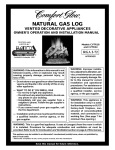
NATURAL GAS LOG
VENTED DECORATIVE APPLIANCES
OWNER’S OPERATION AND INSTALLATION MANUAL
TESTED AND
LISTED BY
Models:
CVTR18/24
HVTR18/24
LVTR18/24
RGA 2-72
Std RADCO Listing No. 1292
APPROVED
WARNING: If the information in this manual is not
followed exactly, a fire or explosion may result
causing property damage, personal injury, or
loss of life.
— Do not store or use gasoline or other flammable
vapors and liquids in the vicinity of this or any
other appliance.
— WHAT TO DO IF YOU SMELL GAS
• Do not try to light any appliance.
• Do not touch any electrical switch; do not use
any phone in your building.
• Immediately call your gas supplier from a
neighbor’s phone. Follow the gas supplier’s
instructions.
• If you cannot reach your gas supplier, call
the fire department.
— Installation and service must be performed by
a qualified installer, service agency, or the
gas supplier.
WARNING: Improper installation, adjustment, alteration, service, or maintenance can cause
injury or property damage. Refer to this manual for correct
installation and operational
procedures. For assistance or
additional information consult
a qualified installer, service
agency, or the gas supplier.
WARNING: This appliance is
for installation only in a solidfuel burning masonry or UL127
factory-built fireplace, constructed of noncombustible
material, and connected to a
working flue. (See page 7 for
minimum flue opening.)
WARNING: This is a gas-fired appliance. It uses air (oxygen) from the room in which
it is installed. Provisions for adequate combustion and ventilation air must be
provided. Refer to Air for Combustion and Ventilation section on page 4 of this manual.
This appliance may be installed in an aftermarket* manufactured (mobile) home, where not prohibited by
state or local codes.
* Aftermarket: Completion of sale, not for purpose of resale, from the manufacturer
Save this manual for future reference.
VENTED NATURAL GAS LOGS
SAFETY
INFORMATION
WARNING ICON
G 001
WARNINGS
1.
2.
WARNING: Keep flue open
when operating unit.
IMPORTANT: Read this owner’s
manual carefully and completely
before trying to assemble, operate, or service this log set. Improper use of this log set can cause
serious injury or death from burns,
fire, explosion, electrical shock,
and carbon monoxide poisoning.
3.
DANGER: Carbon monoxide
poisoning may lead to death!
Carbon Monoxide Poisoning: Early signs
of carbon monoxide poisoning resemble the
flu, with headaches, dizziness, or nausea. If
you have these signs, the log set may not be
working properly. Get fresh air at once!
Have log set serviced. Some people are
more affected by carbon monoxide than
others. These include pregnant women,
people with heart or lung disease or anemia,
those under the influence of alcohol, and
those at high altitudes.
Natural Gas: Natural gas is odorless. An
odor-making agent is added to the gas. The
odor helps you detect a gas leak. However,
the odor added to the gas can fade. Gas may
be present even though no odor exists.
4.
5.
6.
Make certain you read and understand all
warnings. Keep this manual for reference. It
is your guide to safe and proper operation of
this log set.
WARNING: Any change to this
log set or its controls can be
dangerous.
7.
For more information, visit www.desatech.com
This appliance, as supplied, is only for
use with the type of gas indicated on
the rating plate. This appliance is convertible for use with propane/LP, using
the GA9053 or GA9153 pilot kit.
If you smell gas
• shut off gas supply
• do not try to light any appliance
• do not touch any electrical switch; do
not use any phone in your building
• immediately call your gas supplier
from a neighbor’s phone. Follow the
gas supplier’s instructions
• if you cannot reach your gas supplier,
call the fire department
Never install the log set
• in a recreational vehicle
• where curtains, furniture, clothing, or
other flammable objects are less than
42 inches from the front, top, or sides
of the log set
• in high traffic areas
• in windy or drafty areas
Before installing in a solid fuel burning fireplace, the chimney flue and firebox must be cleaned of soot, creosote,
ashes, and loose paint by a qualified
chimney cleaner. Creosote will ignite
if highly heated. Inspect chimney flue
for damage.
You must operate this log set with a fireplace screen in place. Make sure fireplace screen is closed before running
log set. If the fireplace has glass doors,
they must remain OPEN while this log
set is in operation.
This log set is designed to be smokeless. If logs ever appear to smoke, turn
off appliance and call a qualified service person. Note: During initial operation, slight smoking could occur due
to log curing and the burning of manufacturing residues. You may wish to add
more ventilation by opening a window.
To reduce the creation of soot, follow
the instructions in Cleaning and Maintenance, page 11.
2
8.
9.
10.
11.
12.
13.
14.
15.
16.
17.
Do not allow fans to blow directly into
the fireplace. Avoid any drafts that alter burner flame patterns. Ceiling fans
can create drafts that alter burner flame
patterns. Altered burner patterns can
increase sooting.
Do not use a blower insert, heat exchanger insert or other accessory not
approved for use with this log set.
This log set needs fresh, outside air ventilation to run properly. See Air for
Combustion and Ventilation, page 4.
Do not run log set
• where flammable liquids or vapors
are used or stored
• under dusty conditions
Do not burn solid fuel in the fireplace
after installing the log set. Do not use
this log set to cook food or burn paper
or other objects.
Log set becomes very hot when in use.
Keep children and adults away from hot
surface to avoid burns or clothing ignition. Log set will remain hot for a time
after shutdown. Allow surface to cool
before touching.
Carefully supervise young children
when they are in the room with log set.
Do not use appliance if any part has been
exposed to or under water. Immediately
call a qualified service technician to inspect the room appliance and to replace
any part of the control system (if using
GA9053 or GA9153) and any gas control which has been under water.
To help prevent breakage, new logs
must be broken-in (see Curing logs
page 8).
Turn log set off and let cool before servicing, installing, or repairing. Only a
qualified service person should install,
service, or repair log set.
901910
OWNER’S MANUAL
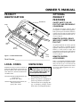
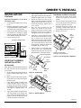
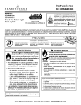
PRODUCT
IDENTIFICATION
OPTIONAL
PRODUCT
FEATURES
Rear Burner
ON/OFF SAFETY VALVE/
PILOT KIT AND PROPANE/LP
CONVERSION
Grate
An optional valve/safety pilot kit with a
piezo ignitor is available for this appliance.
This system requires no matches, batteries,
or other sources to light. You must use this
optional system for LP conversion. See Accessories, page 11.
REMOTE CONTROL READY
(MILLIVOLT) SAFETY VALVE/
PILOT KIT
Burner
Pan
Front
Burner
Valve
Cover
Figure 1 - Product Identification
Serial Number ________________________________________
LOCAL CODES
UNPACKING
Install and use log set with care. Follow all
local codes. In the absence of local codes, use
the latest edition of The National Fuel Gas
Code ANS Z223.1, also known as NFPA 54*.
CAUTION: Do not remove the
metal data plates from the burner
pan. The data plates contain important product information.
*Available from:
American National Standards Institute, Inc.
1430 Broadway
New York, NY 10018
National Fire Protection Association, Inc.
Batterymarch Park
Quincy, MA 02269
901910
1.
2.
3.
An optional millivolt valve/safety pilot kit
with a piezo ignitor is available for this
appliance. This system requires no matches,
batteries, or other sources to light. This
system may be connected to a wall switch or
hand-held wireless remote control. See Accessories, page 11.
REMOTE CONTROL
ACCESSORIES
There is an optional hand-held ON/OFF
remote control that can be purchased separately for this log set. You must use the
millivolt valve/safety pilot kit to use remote
accessories with this appliance. See Accessories, page 11.
Remove logs, hearth kit, pan materials, and hardware from carton.
Remove all protective packaging applied to logs and base for shipment.
Check all items for any shipping damage. If damaged, promptly inform
dealer where you bought the product.
3
For more information, visit www.desatech.com
VENTED NATURAL GAS LOGS
AIR FOR
COMBUSTION AND
VENTILATION
WARNING: This appliance
shall not be installed in a confined space or unusually tight
construction unless provisions
are provided for adequate combustion and ventilation air. Read
the following instructions to insure proper fresh air for this and
other fuel-burning appliances in
your home.
Today’s homes are built more energy efficient than ever. New materials, increased
insulation, and new construction methods
help reduce heat loss in homes. Home owners
weather strip and caulk around windows and
doors to keep the cold air out and the warm air
in. During heating months, home owners
want their homes as airtight as possible.
While it is good to make your home energy
efficient, your home needs to breathe. Fresh
air must enter your home. All fuel-burning
appliances need fresh air for proper combustion and ventilation.
Exhaust fans, fireplaces, clothes dryers, and
fuel burning appliances draw air from the
house to operate. You must provide adequate fresh air for these appliances. This
will insure proper venting of vented fuelburning appliances.
INSTALLATION
CAUTION: Do not remove
the metal data plates attached
to the burner pan. The data plates
contain important warranty information.
WARNING: Before installing
in a solid fuel burning fireplace,
the chimney flue and firebox must
be cleaned of soot, creosote,
ashes, and loose paint by a qualified chimney cleaner. Creosote
will ignite if highly heated. A dirty
chimney flue may create and distribute soot within the house. Inspect chimney flue for damage.
NOTICE: Installation, service, and
repair of this appliance must be
performed by a qualified installer,
service agency, company or gas
supplier experienced with this
type of gas appliance. Only factory authorized components listed
in these instructions may be used
in accordance with the
manufacturer’s instructions and
all codes and requirements of the
authority having jurisdiction. Any
modifications to this kit, or use of
unauthorized components or accessory items will void the
manufacturer’s warranty, and may
result in a hazardous condition.
FLUE OPENING
SPECIFICATIONS
Note: This vented appliance must be installed only in a solid-fuel burning fireplace
with a working flue and constructed of noncombustible material.
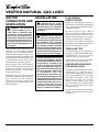
The charts in Figure 2, page 5, indicate
technical information regarding the installation of your gas log set. Please make sure
that all of the specifications shown are applicable before installation is attempted.
The fireplace must include a working flue
and venting system with the minimum openings shown in the Figure 2, page 5.
CHECK GAS TYPE
Use only natural gas. If your gas supply is not
natural gas, you must install ON/OFF Safety
Valve/Pilot Kit (see Accessories, page 11).
Call dealer where you bought log set.
If the fireplace does not have a gas supply
shutoff valve, one must be installed.
VENTING SPECIFICATIONS
FOR INSTALLATION
The fireplace chimney flue and vent must be
drafting properly. To check the vent for
proper drafting: Light a tightly rolled newspaper on one end and place it at the inside
front edge of the fireplace. Observe the
smoke and be sure the vent is properly
drawing it up the chimney. If the smoke
spills out into the room, extinguish the flame
and remove any obstruction until proper
venting is achieved.
The chimney flue must remain open a minimum of 3" at all times during the operation
of this log set.
For more information, visit www.desatech.com
4
901910
OWNER’S MANUAL
INSTALLATION
Continued
Btu Input
Natural Gas
Btu Input
Propane Gas
Minimum
Vent Opening
18" Triple Burner
60,000
50,000
8" dia.
24" Triple Burner
70,000
60,000
8" dia.
MODELS
DESCRIPTION
CVTR18
HVTR18
LVTR18
CVTR24
HVTR24
LVTR24
MINIMUM FIREBOX SIZES
LOG FRONT BACK
SIZE WIDTH* WIDTH**
18"
28"
16"
3
17"
24"
29 /4"
DEPTH HEIGHT
14"
18"
1
15 /2"
18"
*Add 2" if safety valve/pilot is used
**At depth indicated
FUEL INLET PRESSURE
SPECIFICATIONS ("W.C.)
Min.
Max.
NG
5.5
10.5
LP
11
13
BURNER ORIFICE
LOG
NATURAL
PROPANE/LP
SIZE FRONT REAR FRONT REAR
18"
.046 4x.064 .036 4x.043
24"
.064 4x.064 .036 4x.0465
Figure 2 - Technical Information Charts
Continued
901910
5
For more information, visit www.desatech.com
VENTED NATURAL GAS LOGS
INSTALLATION
Continued
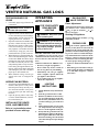
INSTALLING DAMPER
CLAMP
Secure the damper stop clamp provided to
the leading edge of the damper as shown in
Figure 3. If for any reason this clamp doesn't
work on your fireplace, another suitable
clamp or permanent stop must be installed,
or the damper blade must be cut or removed.
Damper Clamp
Damper
Damper
Masonry Fireplace
Manufactured
Fireplace
CAUTION: Use only new,
black iron or steel pipe. Internally-tinned copper tubing may
be used in certain areas. Check
your local codes. Use pipe of 1/2"
diameter or greater to allow
proper gas volume to log set. If
pipe is too small, undue loss of
pressure will occur.
WARNING: Test all gas piping and connections for leaks
after installing or servicing. Correct all leaks at once.
WARNING: Never use an
open flame to check for a leak.
Apply a mixture of liquid soap
and water to all joints. Bubbles
forming show a leak. Correct all
leaks at once.
IMPORTANT: Install equipment shutoff
valve in an accessible location. The equipment shutoff valve is for turning on or
shutting off the gas to the appliance.
Apply pipe joint sealant lightly to male
threads. This will prevent excess sealant
from going into pipe. Excess sealant in pipe
could result in a clogged burner injector.
Figure 3 - Attaching Damper Clamp
Install sediment trap in supply line as shown
in Figure 4. Locate sediment trap where it is
within reach for cleaning. Locate sediment
trap where trapped matter is not likely to
CONNECTING TO GAS
SUPPLY
Approved Flexible Gas Hose
(if allowed by local codes)
Damper
CHECKING GAS
CONNECTIONS
Installation must include an equipment
shutoff valve, union, and plugged 1/8" NPT
tap. Locate NPT tap within reach for test
gauge hook up. NPT tap must be upstream
from log set (see Figure 4).
CAUTION: Use pipe joint sealant that is resistant to liquid petroleum (LP) gas.
Damper
Clamp
freeze. A sediment trap traps moisture and
contaminants. This keeps them from going
into log set controls. If sediment trap is not
installed or is installed wrong, log set may
not run properly.
Pressure Testing Gas Supply
Piping System
Test Pressures In Excess Of 1/2 PSIG
(3.5 kPa)
1.
2.
3.
4.
WARNING: A qualified service person must connect log set
to gas supply. Follow all local
codes.
CSA Design-Certified
Equipment Shutoff Valve
With 1/8" NPT Tap*
Installation Items Needed
Before installing log set, make sure you
have the items listed below.
• piping (check local codes)
• sealant (resistant to propane/LP gas)
• equipment shutoff valve
• test gauge connection
• adjustable (crescent) wrench or pliers
• sediment trap
• tee joint
• pipe wrench
3" Minimum
Cap
Figure 4 - Gas Connection
5.
6.
Disconnect appliance with its appliance
main gas valve (control valve) and equipment shutoff valve from gas supply piping system. Pressures in excess of 1/2
psig will damage heater regulator.
Cap off open end of gas pipe where
equipment shutoff valve was connected.
Pressurize supply piping system by either
using compressed air or opening main gas
valve located on or near gas meter.
Check all joints of gas supply piping
system. Apply mixture of liquid soap
and water to gas joints. Bubbles forming show a leak.
Correct all leaks at once.
Reconnect log set and equipment
shutoff valve to gas supply. Check reconnected fittings for leaks.
From Gas Meter (5" W.C.**
to 10.5" W.C. Pressure)
Pipe Nipple Tee Joint
Sediment Trap
* Purchase the optional CSA design-certified equipment shutoff valve from your dealer. See
Accessories, page 11.
** Minimum inlet pressure for purpose of input adjustment.
For more information, visit www.desatech.com
6
901910
OWNER’S MANUAL
INSTALLATION
5.
Continued
Test Pressures Equal To or Less Than
1/2 PSIG (3.5 kPa)
1.
2.
3.
4.
Close equipment shutoff valve (see Figure 5).
Pressurize supply piping system by either
using compressed air or opening main gas
valve located on or near gas meter.
Check all joints from gas meter to equipment shutoff valve (see Figure 5). Apply
mixture of liquid soap and water to gas
joints. Bubbles forming show a leak.
Correct all leaks at once.
6.
7.
8.
Equipment Shutoff Valve
Gas Meter
9.
Apply thread sealant to the 1/8" brass
pipe nipple and thread it onto the manifold block. Tighten with a 7/16" wrench.
Slip the air restrictor over the 1/8" pipe
nipple. Apply thread sealant to the male
threads and install the rear burner
nozzle onto the fitting. Tighten with a
9/16" wrench.
Place the grate assembly over the
burner pan. Install the rear burner
bracket onto the grate with the 2 black
Phillips head #10 screws provided. Do
not tighten at this time (see Figure 7).
Install the “U” burner from the left side
with the open end in the front (see Figure 7). Hold the rear of the burner
higher than the bracket. Slide the burner
over the air restrictor fitting. Lower the
rear of the burner into the slots on the
burner bracket. Install the burner clip
and tighten the nuts and screws.
Install 3/8 flare x 3/8 male pipe elbow
into the inlet of the manifold block.
Install the pipe plug into the top of the
manifold block. Use thread sealant.
Rear Burner Nozzle
Installation and Gas Connection
1.
2.
3.
4.
Thread the gas supply fitting to the
fireplace gas supply pipe. Use thread
sealant.
Place the burner pan assembly in the
center of the fireplace floor. Make sure
the front of pan faces forward.
Install the flex gas line to the gas supply fitting. Carefully shape tube to attach to adapter fitting (see Figure 8).
Replace valve cover.
Gas
Supply
Fitting
Flex Gas Line
Burner Pan Assembly
(Facing Front of Fireplace)
Figure 8 - Connecting Gas to Appliance
Figure 5 - Checking Gas Joints
Air Restrictor
HEARTH KIT ASSEMBLY
AND INSTALLATION
Pipe
Nipple
Kit Assembly
Note: Be sure all pipe threaded connections
are tight, and have thread compound to
prevent leaks.
1. Remove burner inlet fitting from front
burner (installed in burner pan, see Figure 6).
2. Make sure ports on front burner are facing the front (open side) of burner pan.
Refit if needed.
3. Using thread sealant (resistant to the
action of propane/LP gas) on larger end
of fitting, screw the burner inlet fitting
through the hole and into the front burner
(see Figure 6). Tighten using a 7/8"
wrench.
4. Apply thread sealant compound to the
3/8" male threads of the burner inlet
fitting. Thread the manifold block (see
Figure 6) onto the burner inlet fitting.
Use the bottom hole of the block.
Front
Burner Burner
Inlet
Fitting
Manifold
Block
Figure 6 - Kit Assembly
Burner
Bracket
Grate
Burner
Clip
Pipe
Plug
Burner Pan
Pipe Elbow
Figure 7 - Installing Burner
Continued
901910
7
For more information, visit www.desatech.com
VENTED NATURAL GAS LOGS
TESTING BURNER FOR
LEAKS
1.
Generously apply soapy solution to all
connections.
OPERATING
APPLIANCE
FOR YOUR SAFETY
READ BEFORE
LIGHTING
WARNING: Never check for
gas leaks with open flame.
2.
3.
4.
5.
Light the burner with the shutoff valve
no more than half open and holding a
match slightly in front of the pan (see
Lighting Instructions, column 2).
Inspect all connections for bubbles, raw
gas odor, or flame from any area other
than the burner (leaks). If leaks are detected, shut off the gas valve immediately. Tighten, or reassemble the loose
connection(s) using pipe joint compound until burner system is leak free.
When the burner is tested and leak free,
observe the individual tongues of flame
on the burner. Note: The burner design
includes more ports on the outside of the
bar. Make sure that all ports are clear
and producing flame evenly across the
burner. If any ports appear blocked, clear
them by removing the burner manifold
and reaming the ports with a modified
paper clip or other suitable tool.
When finished testing, turn the gas
shutoff valve OFF to extinguish all
flames.
ADDING PAN MATERIAL
1.
2.
Open the bag of Ash Bed Material (vermiculite) and spread it evenly across
the burner pan to the top. You may overflow the front and sides of the pan to
cover the entire pan and connecting
hardware.
Open the glowing embers and evenly
cover the Ash Bed Material (vermiculite) in the burner pan.
INSTALLING THE GRATE,
LOGS, AND EMBER BED
Refer to Log Installation sheet
provided in carton with logs.
WARNING: Keep flue open
when operating unit.
WARNING: If you do not follow these instructions exactly, a
fire or explosion may result causing property damage, personal
injury or loss of life.
BEFORE LIGHTING smell all around
the appliance area for gas. Be sure to
smell next to the floor because some gas is
heavier than air and will settle on the
floor.
WHAT TO DO IF YOU SMELL GAS
• Do not try to light any appliance.
• Do not touch any electric switch; do
not use any phone in your building.
• Immediately call your gas supplier
from a neighbor’s phone. Follow the
gas supplier’s instructions.
• If you cannot reach your gas supplier,
call the fire department.
GAS SHUTOFF
VALVE OPERATION
Flame Adjustment
Adjust the flame ON/OFF by turning the
gas shutoff valve counterclockwise
to open or clockwise
to
close, as necessary.
Shutting Off Appliance
Turn gas shutoff valve clockwise
to the OFF position.
CURING LOGS
During the 2-3 hour appliance break-in
period, you may detect an odor from the
appliance as the various paints and compounds used in the manufacturing of this
log set cure. This is a normal and temporary situation that is not cause for alarm.
However, you may want to provide extra
ventilation to the room during this time.
To ensure proper curing of the logs:
• Ignite a 2" flame and maintain it for 1
hour.
• Burn the logs in consecutive 1 hour periods raising the flame an additional
2" to full flame height for a total of
three hours.
LIGHTING
INSTRUCTIONS
1.
2.
3.
4.
5.
For more information, visit www.desatech.com
STOP! Read the safety information,
above.
Turn the gas shutoff valve to OFF.
Wait five (5) minutes to clear out any
gas. If you then smell gas STOP! Follow the safety information above. If
you don’t smell gas, go on to the next
step.
Light a match and lay it on top of the
“U” shaped burner near the edge of
the cover on the right side of the pan.
Slowly turn the gas shutoff valve ON
until the burner ignites. If the burner
doesn’t ignite within 10 seconds with
the match burning, turn the shutoff
valve OFF and repeat steps 1 through
4 again.
8
901910
OWNER’S MANUAL
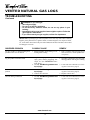
TROUBLESHOOTING
Note: For additional help, visit DESA
International’s technical service web site
at www.desatech.com.
WARNING: Turn off log set
and let cool before servicing. Only
a qualified service person should
service and repair log set.
Note: All troubleshooting items are listed in
order of operation.
OBSERVED PROBLEM
POSSIBLE CAUSE
REMEDY
Log set is smoking/sooting excessively
(Note: It is natural and unavoidable for
vented gas log sets to produce moderate
levels of carbon (soot) where flames
contact the logs. This is especially true
with propane/LP gas.)
1. Poor fuel quality
5. Excessive gas supply/pressure
1. Contact local natural or propane/LP gas
company
2. Adjust damper wide open and/or have
fireplace and venting professionally
cleaned and checked
3. Separate the logs to allow more flame
passage
4. Remove any foreign items from the
flame pattern and/or check for proper
orifice sizing
5. Preheat flue in very cold weather
Burner is excessively noisy
(Note: The movement and combustion of gas
will create low, unavoidable levels of noise.)
1. Passage of air/gas across irregular surfaces
1. Relieve any tight bends or kinks in gas
supply line
Burner flame is too low or too high
1. Incorrect gas supply or pressure
2. Blocked burner orifice or burner manifold ports
3. Improper burner orifice size
1. Check for proper gas supply pressure
2. Free burner orifice and manifold ports
of any burrs, paint, or other blockage
3. Verify proper burner orifice sizing (see
Figure 2, page 5)
2. Fireplace venting system not drafting
properly
3. Excessive flame impingement or
blockage
4. Improper fuel/air mixture
www.desatech.com
901910
9
Continued
For more information, visit www.desatech.com
VENTED NATURAL GAS LOGS
TROUBLESHOOTING
Continued
WARNING: If you smell gas
• Shut off gas supply.
• Do not try to light any appliance.
• Do not touch any electrical switch; do not use any phone in your
building.
• Immediately call your gas supplier from a neighbor’s phone. Follow the
gas supplier’s instructions.
• If you cannot reach your gas supplier, call the fire department.
IMPORTANT: Operating log set where impurities in air exist may create odors. Cleaning
supplies, paint, paint remover, cigarette smoke, cements and glues, new carpet or textiles,
etc., create fumes. These fumes may mix with combustion air and create odors. These odors
will disappear over time.
OBSERVED PROBLEM
POSSIBLE CAUSE
REMEDY
Log Set produces a clicking/ticking noise
just after burner is lit or shut off
1. Metal expanding while heating or contracting while cooling
1. This is common with most log sets. If
noise is excessive, contact qualified service person
Log Set produces unwanted odors
1. Log Set burning vapors from paint, hair
spray, glues, cleaners, chemicals, new
carpet, etc. (See IMPORTANT statement above)
2. Gas leak. See Warning statement at
top of page
1. Open flue to maximum. Stop using odor
causing products while log set is running
Gas odor even when control knob is in OFF
position
1. Gas leak. See Warning statement at
top of page
2. Control valve defective
1. Locate and correct all leaks (see Checking Gas Connections, page 6)
2. Replace control valve
Gas odor during combustion
1. Gas leak. See Warning statement at
top of page
2. Locate and correct all leaks (see Checking Gas Connections, page 6)
2. Locate and correct all leaks (see Checking Gas Connections, page 6)
www.desatech.com
For more information, visit www.desatech.com
10
901910
OWNER’S MANUAL
CLEANING AND
MAINTENANCE
• Keep the area around the log set clean
and clear of debris.
• Occasionally, you may use a soft bristle
brush to clean logs.
• Once every year a qualified agency or
certified chimney sweep should examine and clean the venting system of the
fireplace.
PINE CONES - GA9650
ACCESSORIES
Purchase these fireplace accessories from
your local dealer. If they can not supply
these accessories, call DESA International’s
Sales Department at 1-800-432-2382 for
information. You can also write to the address listed on the back page of this manual.
(Not Shown)
For all models. Use for additional decoration only. Carton of 6 Boxes (3 pine cones
per box).
ASH BED MATERIAL
(Vermiculite) - GA9750
(Not Shown)
For all models. Carton of 6.
GLOWING EMBERS - GA9950
(Not Shown)
REPLACEMENT
PARTS
For all models. Use for firebox decoration
only.
Note: Use only original replacement parts.
SILICA SAND - GA9850
This will protect your warranty coverage for
parts replaced under warranty.
EQUIPMENT SHUTOFF
VALVE - GA5010
PARTS UNDER WARRANTY
For all models. Equipment shutoff valve with
1/8" NPT tap. Fits 1/2" NPT pipe.
Contact authorized dealers of this product or
Parts Central (see page 14). If they can’t
supply original replacement part(s), call DESA
International’s Technical Service Department
at 1-800-DESA LOG (1-800-337-2564).
When calling DESA International, have ready
• your name
• your address
• model and serial numbers of your fireplace
• how fireplace was malfunctioning
• type of gas used (propane/LP or natural
gas)
• purchase date
Usually, we will ask you to return the defective part to the factory.
PARTS NOT UNDER WARRANTY
Contact authorized dealers of this product
or Parts Central (see page 14). If they can’t
supply original replacement part(s), call
DESA International’s Parts Department at
1-800-972-7879 for referral information.
When calling DESA International, have ready
• model number of your fireplace
• the replacement part number
901910
(Not Shown)
For all models. Use for firebox decoration
only. Carton of 6.
LAVA ROCK - GA6067
(Not Shown)
For all models. Use for firebox decoration
only.
DECORATIVE ASH BED
CONTROL COVER - CDABK
(Not Shown)
RECEIVER AND HANDHELD REMOTE CONTROL
KIT - GHRC Series
An attractive way to cover control knob
and piezo ignitor.
For all models. Allows the gas log set to be
turned on and off by using a hand-held
remote control. Valve/Pilot Kit GA9153
must be used with this remote.
ON/OFF SAFETY VALVE/
PILOT KIT - GA9053-1
For all models. Required for Propane/LP
installation.
(Not Shown)
(Not Shown)
For 18" models only. Additional decoration
for front grate.
24" ORNAMENTAL GRATE
ENHANCER - GA9360
(Not Shown)
REMOTE READY VALVE/
PILOT KIT - GA9153-1
18" ORNAMENTAL GRATE
ENHANCER - GA9350
(Not Shown)
For 24" models only. Additional decoration
for front grate.
30" ORNAMENTAL GRATE
ENHANCER - GA9370
(Not Shown)
For all models.
For 30" models only. Additional decoration
for front grate.
11
For more information, visit www.desatech.com
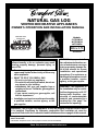
VENTED NATURAL GAS LOGS
ILLUSTRATED
PARTS
BREAKDOWN
Triple Burner Models
2
4
1
5
6
5
3
15
17
18
8
9
14
12
13
19
7
16
10
11
For more information, visit www.desatech.com
12
901910
OWNER’S MANUAL
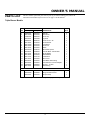
PARTS LIST
This list contains replaceable parts used in your log set. When ordering parts, follow the
instructions listed under Replacement Parts on page 11 of this manual.
Triple Burner Models
KEY PART NUMBER FOR
NO.
18" Triple
24" Triple
DESCRIPTION
QTY.
1
2
3
4
5
6
7
8
9
10
11
12
13
14
15
16
17
18
19
098249-01
901752-02
102843-01
901246-01
098304-01
901762-01
901754-02
901753-02
901750-01
901064-05
901066-01
901761-01
901760-01
901751-01
901756-01
901056-01
901058-01
101628-01
901759-01
098249-01
901752-01
102843-01
901246-02
098304-01
901762-01
901754-01
901753-01
901750-01
901064-01
901066-01
901761-01
901760-01
901751-01
901756-01
901056-01
901058-01
101628-01
901759-01
ODS Nut
Rear Burner
Burner Clip
Log Grate
Screw, 10-16 x .38
Burner Bracket
Front Burner
Burner Pan
Nozzle
Natural Gas Injector
Brass Air Mixer - Natural Gas
1/8 Hex Nipple
Manifold Block
Air Restrictor
Valve Cover
Brass Elbow Flare Fitting
Brass 3/8 FLR x 1/2 FPT Adapter
Gas Line - 10" Flex
Manifold Plug
2
1
1
1
4
1
1
1
1
1
1
1
1
1
1
1
1
1
1
PARTS AVAILABLE — NOT SHOWN
901036-01
901039-08
901242-01
901036-01
901038-04
901242-01
RADCO GEN Rating Plate
Rating Information Plate
Damper Clamp
1
1
1
Note: Refer to Log Installation sheet for specific log replacement part numbers
901910
13
For more information, visit www.desatech.com
VENTED NATURAL GAS LOGS
PARTS CENTRALS
These Parts Centrals are privately-owned businesses. They have agreed to support our
customer’s needs by providing original replacement parts and accessories.
Baltimore Electric
1348 Dixwell Avenue
Hamden, CT 06514-0322
1-800-397-7553
203-248-7553
Parts Department
Washer Equipment Co.
1715 Main Street
Kansas City, MO 64108-2195
KS, MO, AR
816-842-3911
Parts Department
Halco Enterprises
208 Carter Drive, Unit 21
West Chester, PA 19382-4500
610-430-7717
1-800-368-0803
Parts Department
Portable Heater Parts
342 N. County Rd. 400 E.
Valparaiso, IN 46383-9704
All States
219-462-7441
1-800-362-6951
Parts Department
East Coast Energy Products
707 Broadway
W. Long Branch, NJ 07764-1542
732-870-8809
1-800-755-8809
Parts Department
Laportes Parts and Service
2444 North 5th Street
Hartsville, SC 29550-7704
803-332-0191
Parts Department
FBD
1349 Adams St.
Bowling Green, KY 42103-3414
270-846-1199
1-800-654-8534
Fax: 1-800-846-0090
Master Parts Distributor
1251 Mound Ave. NW
Grand Rapids , MI 49504-2672
616-791-0505
1-800-446-1446
Fax: 1-616-791-8270
Parts Department
Dayton Hardware
P.O. Box 275
North Dayton Station
Dayton, OH 45404-0275
All States
513-258-3721
OH 1-800-762-3426
Parts Department
For more information, visit www.desatech.com
14
Cans Unlimited, Inc.
P.O. Box 645
Taylor, SC 29687-0013
All States
803-879-3009
1-800-845-5301
Parts Department
901910
OWNER’S MANUAL
NOTES
_______________________________________________________________________________________________
_______________________________________________________________________________________________
_______________________________________________________________________________________________
_______________________________________________________________________________________________
_______________________________________________________________________________________________
_______________________________________________________________________________________________
_______________________________________________________________________________________________
_______________________________________________________________________________________________
_______________________________________________________________________________________________
_______________________________________________________________________________________________
_______________________________________________________________________________________________
_______________________________________________________________________________________________
_______________________________________________________________________________________________
_______________________________________________________________________________________________
_______________________________________________________________________________________________
_______________________________________________________________________________________________
_______________________________________________________________________________________________
_______________________________________________________________________________________________
_______________________________________________________________________________________________
_______________________________________________________________________________________________
_______________________________________________________________________________________________
_______________________________________________________________________________________________
_______________________________________________________________________________________________
_______________________________________________________________________________________________
_______________________________________________________________________________________________
_______________________________________________________________________________________________
_______________________________________________________________________________________________
_______________________________________________________________________________________________
_______________________________________________________________________________________________
_______________________________________________________________________________________________
_______________________________________________________________________________________________
_______________________________________________________________________________________________
_______________________________________________________________________________________________
_______________________________________________________________________________________________
901910
15
For more information, visit www.desatech.com
WARRANTY INFORMATION
KEEP THIS WARRANTY
Model
Serial No.
Date Purchased
Always specify model and serial numbers when communicating with the factory.
We reserve the right to amend these specifications at any time without notice. The only warranty applicable is our standard written
warranty. We make no other warranty, expressed or implied.
LIMITED WARRANTY
COMFORT GLOW VENTED GAS LOGS
DESA International warrants this product to be free from defects on burner system for two (2) years and logs for a lifetime from the
date of first purchase, provided that the product has been properly installed, operated and maintained in accordance with all applicable
instructions. To make a claim under this warranty the Bill of Sale or cancelled check must be presented.
This warranty is extended only to the original retail purchaser. This warranty covers the cost of part(s) required to restore this log set
to proper operating condition and an allowance for labor when provided by a DESA Authorized Service Center. Warranty part(s) MUST
be obtained through authorized dealers of this product and/or DESA International who will provide original factory replacement parts.
Failure to use original factory replacement parts voids this warranty. The log set MUST be installed by a qualified installer in accordance
with all local codes and instructions furnished with the unit.
This warranty does not apply to parts that are not in original condition because of normal wear and tear, or parts that fail or become
damaged as a result of misuse, accidents, lack of proper maintenance or defects caused by improper installation. Travel, diagnostic cost,
labor, transportation and any and all such other costs related to repairing a defective log set will be the responsibility of the owner.
TO THE FULL EXTENT ALLOWED BY THE LAW OF THE JURISDICTION THAT GOVERNS THE SALE OF THE PRODUCT;
THIS EXPRESS WARRANTY EXCLUDES ANY AND ALL OTHER EXPRESSED WARRANTIES AND LIMITS THE DURATION OF ANY AND ALL IMPLIED WARRANTIES, INCLUDING WARRANTIES OF MERCHANTABILITY AND FITNESS
FOR A PARTICULAR PURPOSE TO TWO (2) YEARS ON BURNER SYSTEM AND A LIFETIME ON LOGS FROM THE DATE
OF FIRST PURCHASE; AND DESA INTERNATIONAL’S LIABILITY IS HEREBY LIMITED TO THE PURCHASE PRICE OF
THE PRODUCT AND DESA INTERNATIONAL SHALL NOT BE LIABLE FOR ANY OTHER DAMAGES WHATSOEVER
INCLUDING INDIRECT, INCIDENTAL OR CONSEQUENTIAL DAMAGES.
Some states do not allow a limitation on how long an implied warranty lasts or an exclusion or limitation of incidental or consequential
damages, so the above limitation on implied warranties, or exclusion or limitation on damages may not apply to you.
This warranty gives you specific legal rights, and you may also have other rights that vary from state to state.
For information about this warranty write:
INTERNATIONAL
2701 Industrial Drive
P.O. Box 90004
Bowling Green, KY 42102-9004
www.desatech.com
901910 01
NOT A UPC
901910-01
Rev. A
08/00