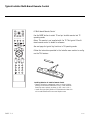
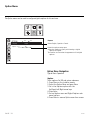
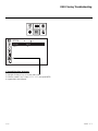
1
26LG3DCH-UA 32LG3DCH-UA
Hospital TVs
Commercial Mode Setup Guide
Note: All features shown within this guide
may not be available on all models.
Experienced Installer
Commercial Mode Setup
page 7
Cloning Information
pages 29 / 30 / 31-32-33
©
Copyright 2008, LG Electronics U.S.A., Inc.
For Customer Support/Service, please call:
1-888-865-3026
www.lgcommercial.com
RECORD Model and SERIAL NUMBER
The model and serial number of this TV is located on the
back of the cabinet. For future reference, we suggest that
you record those numbers here:
Model No._________________Serial No. _______________
WARNING
RISK OF ELECTRIC SHOCK
DO NOT OPEN
WARNING: TO REDUCE THE RISK OF ELECTRIC SHOCK DO NOT REMOVE COVER (OR BACK). NO USER
SERVICEABLE PARTS INSIDE. REFER TO QUALIFIED SERVICE PERSONNEL
The lightning flash with arrowhead symbol, within an equilateral triangle, is intended to alert the user to the
presence of uninsulated “dangerous voltage” within the product’s enclosure that may be of sufficient magnitude
to constitute a risk of electric shock to persons.
The exclamation point within an equilateral triangle is intended to alert the user to the presence of important
operating and maintenance (servicing) instructions in the literature accompanying the appliance
WARNING:
TO PREVENT FIRE OR SHOCK HAZARDS, DO NOT EXPOSE THIS PRODUCT TO RAIN OR MOISTURE.
POWER CORD POLARIZATION:
This product is equipped with a 3-wire grounding-type alternating current line plug. This plug will fit into the power outlet
only one way. This is a safety feature. If you are unable to insert the plug fully into the outlet, contact your electrician to
replace your obsolete outlet. Do not defeat the safety purpose of the three-wire ground type plug.
NOTE TO CABLE/TV INSTALLER:
This reminder is provided to call the cable TV system installer’s attention to Article 820-40 of the National Electric Code
(U.S.A.). The code provides guidelines for proper grounding and, in particular, specifies that the cable ground shall be connected to the grounding system of the building, as close to the point of the cable entry as practical.
REGULATORY INFORMATION:
This equipment has been tested and found to comply with the limits for a Class B digital device, pursuant to Part 15 of the
FCC Rules. These limits are designed to provide reasonable protection against harmful interference when the equipment is
operated in a residential installation. This equipment generates, uses and can radiate radio frequency energy and, if not
installed and used in accordance with the instruction manual, may cause harmful interference to radio communications.
However, there is no guarantee that interference will not occur in a particular installation. If this equipment does cause
harmful interference to radio or television reception, which can be determined by turning the equipment off and on, the user
is encouraged to try to correct the interference by one or more of the following measures:
• Reorient or relocate the receiving antenna.
• Increase the separation between the equipment and receiver.
• Connect the equipment into an outlet on a circuit different from that to which the receiver is connected.
• Consult the dealer or an experienced radio/TV technician for help.
CAUTION:
Do not attempt to modify this product in any way without written authorization from LG Electronics U.S.A., Inc.
Unauthorized modification could void the user’s authority to operate this product.
COMPLIANCE:
The responsible party for this product’s compliance is: LG Electronics U.S.A., Inc.
1000 Sylvan Avenue, Englewood Cliffs, NJ 07632, USA • Phone: 1-201-816-2000.
Marketed and Distributed in the United States by LG Electronics U.S.A., Inc.
2000 Millbrook Drive, Lincolnshire, IL 60069
PAGE 2
© Copyright 2008, LG Electronics U.S.A., Inc.
206-4071
IMPORTANT SAFETY INSTRUCTIONS
SAFETY INSTRUCTIONS
Important safeguards for you and your new product
This product has been manufactured and tested with safety in mind. However, improper use can result in potential electrical shock
or fire hazards. To avoid defeating the safeguards that have been built into the new product, please read and observe the following
safety points when installing and using the new product, and save them for future reference.
Observing the simple precautions discussed in this installation and operating guide can help get many years of enjoyment and safe
operation that are built into the new product.
This product complies with all applicable U.S. Federal safety requirements, and those of the Canadian Standards Association
1. Read Instructions
8. Transporting Product
All the safety and operating instructions should be read before
the product is operated.
2. Follow Instructions
A product and cart combination should be moved with care.
Quick stops, excessive force, and uneven surfaces may cause the
product and cart combination to overturn.
All operating and use instructions should be followed.
9. Attachments
3. Retain Instructions
Do not use attachments not recommended by the product manufacturer as they may cause hazards.
The safety and operating instructions should be retained for
future reference.
10. Ventilation
Unplug this product from the wall outlet before cleaning. Do
not use liquid cleaners or aerosol cleaners. Use a damp cloth
for cleaning.
Slots and openings in the cabinet are provided for ventilation
and to ensure reliable operation of the product and to protect
it from overheating, and these openings must not be blocked or
covered. The openings should never be blocked by placing the
product on a bed, sofa, rug, or other similar surface. This product should not be placed in a built-in installation such as a
bookcase or rack unless proper ventilation is provided or the
manufacturer’s instructions have been adhered to.
6. Water and Moisture
11. Power Sources
Do not use this product near water for example, near a bath
tub, wash bowl, kitchen sink, or laundry tub, in a wet basement, or near a swimming pool.
This product should be operated only from the type of power
source indicated on the marking label. If you are not sure of
the type of power supply to your home, consult your product
dealer or local power company. For products intended to operate from battery power, or other sources, refer to the operating
instructions.
4. Heed Warnings
All warnings on the product and in the operating instructions
should be adhered to.
5. Cleaning
7. Accessories, Carts, and Stands
Do not place this product on a slippery or tilted surface, or on
an unstable cart, stand, tripod, bracket, or table. The product
may slide or fall, causing serious injury to a child or adult, and
serious damage to the product. Use only with a cart, stand, tripod, bracket, or table recommended by the manufacturer, or
sold with the product. Any mounting of the product should follow the manufacturer’s instructions, and should use a mounting
accessory recommended by the manufacturer.
12. Power Cord Polarization (Some models)
This product is equipped with a three-wire grounding type
alternating-current power plug. This plug will fit into the power
outlet only one way. This is a safety feature. If you are unable
to insert the plug fully into the outlet, contact your electrician
to replace your obsolete outlet. Do not defeat the safety purpose of the three-wire ground-type plug.
13. Power Cord Protection
Power-supply cords should be routed so that they are not likely
to be walked on or pinched by items placed upon or against
them, paying particular attention to cords at plugs, convenience receptacles, and the point where they exit from the product.
PORTABLE CART WARNING
206-4071
PAGE 3
IMPORTANT SAFETY INSTRUCTIONS
(Continued from previous page)
14. Outdoor Antenna Grounding
If an outside antenna or cable system is connected to the
product, be sure the antenna or cable system is grounded so as
to provide some protection against voltage surges and built-up
static charges. Article 810 of the National Electrical Code
(U.S.A.), ANSI/ NFPA 70 provides information with regard to
proper grounding of the mast and supporting structure,
grounding of the lead-in wire to an antenna discharge unit,
size of grounding conductors, location of antenna-discharge
unit, connection to grounding electrodes, and requirements for
the grounding electrode.
Example of Grounding According to National Electrical
Code Instructions
Ground Clamp
Antenna Lead in Wire
Antenna Discharge Unit
(NEC Section 810-20)
Electric Service
Equipment
Grounding Conductor
(NEC Section 810-21)
Ground Clamps
Power Service Grounding
Electrode System (NEC
Art 250, Part H)
NEC - National Electrical Code
15. Lightning
For added protection for this product (receiver) during a lightning storm, or when it is left unattended and unused for long
periods of time, unplug it from the wall outlet and disconnect
the antenna or cable system. This will prevent damage to the
product due to lightning and power-line surges.
16. Power Lines
An outside antenna system should not be located in the vicinity of overhead power lines or other electric light or power circuits, or where it can fall into such power lines or circuits.
When installing an outside antenna system, extreme care
should be taken to keep from touching such power lines or circuits as contact with them might be fatal.
17. Overloading
Do not overload wall outlets and extension cords as this can
result in a risk of fire or electric shock.
18. Object and Liquid Entry
Never push objects of any kind into this product through
openings as they may touch dangerous voltage points or
PAGE 4
short-out parts that could result in a fire or electric shock.
Never spill liquid of any kind on the product.
19. Servicing
Do not attempt to service this product yourself as opening or
removing covers may expose you to dangerous voltage or other
hazards. Refer all servicing to qualified service
personnel.
20. Damage Requiring Service
Unplug this product from the wall outlet and refer servicing to
qualified service personnel under the following
conditions:
a. If the power-supply cord or plug is damaged.
b. If liquid has been spilled, or objects have fallen into the
product.
c. If the product has been exposed to rain or water.
d. If the product does not operate normally by following the
operating instructions. Adjust only those controls that are
covered by the operating instructions as an improper
adjustment of other controls may result in damage and will
often require extensive work by a qualified technician to
restore the product to its normal operation.
e. If the product has been dropped or the cabinet has been
damaged.
f. If the product exhibits a distinct change in performance.
21. Replacement Parts
When replacement parts are required, be sure the service technician has used replacement parts specified by the manufacturer or have the same characteristics as the original part.
Unauthorized substitutions may result in fire, electric shock, or
other hazards.
22. Safety Check
Upon completion of any service or repairs to this product, ask
the service technician to perform safety checks to determine
that the product is in proper operating condition.
23. Wall or Ceiling Mounting
The product should be mounted to a wall or ceiling only as recommended by the manufacturer. The product may slide or fall,
causing serious injury to a child or adult, and serious damage
to the product.
24. Heat
The product should be situated away from heat sources such as
radiators, heat registers, stoves, or other products (including
amplifiers) that produce heat.
206-4071
Table of Contents
Use this page as a reference to find pages or sections to go to and set up the TV features.
Go to page 7 to begin the Commercial Mode Master TV setup.
1.
2.
3.
4.
Connect TV to RF signal and Auxiliary sources.
Customize TV features and set up other operational controls in the Installer’s menu.
Copy the Master TV setup into the clone programmer.
Transfer the Master TV setup from the clone programmer to identical TVs.
Warnings . . . . . . . . . . . . . . . . . . . . . . . . . . . . . . . . . . 2
Important Safety Instructions . . . . . . . . . . . . . . . . . . 3 - 4
Table of Contents . . . . . . . . . . . . . . . . . . . . . . . . . . . . 5
Setup Checklist . . . . . . . . . . . . . . . . . . . . . . . . . . . . 6
Commercial Mode Setup . . . . . . . . . . . . . . . . . . . . . . 7
Installer Overview . . . . . . . . . . . . . . . . . . . . . . . . . . . . 8
TV Overview . . . . . . . . . . . . . . . . . . . . . . . . . . . . . . . . 9
Typical Installer’s Remote Control . . . . . . . . . . . . . . . . . 10
Remote Key Functions . . . . . . . . . . . . . . . . . . . . . . . . .11
Rear Connections Panel . . . . . . . . . . . . . . . . . . . . . . . . 12
A/V Input 2 Side Connections Panel/RF Antenna Connection 13
MPI Card Slot / PPV Card Installation . . . . . . . . . . . . . . . 14
Vesa Standard TV Mounts . . . . . . . . . . . . . . . . . . . . . . . 15
Pillow Speaker Connections . . . . . . . . . . . . . . . . . . . . . 16
Features Setup Menus Overview . . . . . . . . . . . . . . . . . . . 17
Channel Menu . . . . . . . . . . . . . . . . . . . . . . . . . . . . . . 18
Picture Menu . . . . . . . . . . . . . . . . . . . . . . . . . . . . . . . 19
Audio Menu . . . . . . . . . . . . . . . . . . . . . . . . . . . . . . . 20
Time Menu . . . . . . . . . . . . . . . . . . . . . . . . . . . . . . . . 21
Option Menu . . . . . . . . . . . . . . . . . . . . . . . . . . . . . . . 22
Lock Menu . . . . . . . . . . . . . . . . . . . . . . . . . . . . . . . . 23
Channel Banks Setup . . . . . . . . . . . . . . . . 24 - 25 - 26 USB Software Upgrades . . . . . . . . . . . . . . . . . . . . . . . .
USB Learn / Teach . . . . . . . . . . . . . . . . . . . . . . . . . . .
TLL-1100A Cloning Instructions . . . . . . . . . . . . . . . . . .
LT2002 Cloning Instructions . . . . . . . . . . . . . . 31 - 32 Installer Menus . . . . . . . . . . . . 34 - 35 - 36 - 37 - 38 -
27
28
29
30
33
39
References
Detailed Instructions For Making A Master TV . . . . . . . . .
Editing Channel Icons/Adding Ch Labels 2-5-4 + Menu Mode
Clonable Menu Features Chart . . . . . . . . . . . . . . . . . . . .
Checking Software Version . . . . . . . . . . . . . . . . . . . . . .
USB Cloning Troubleshooting . . . . . . . . . . . . . . . . . . . .
TV Camport Auto Sense Operation . . . . . . . . . . . . . . . . .
TV Aux Input Configuration / Power Savings Setup . . . . .
Troubleshooting . . . . . . . . . . . . . . . . . . . . . . . . . . . . .
Cloning Troubleshooting . . . . . . . . . . . . . . . . . . . . . . .
Channel Banks Setup Troubleshooting . . . . . . . . . . . . . .
Troubleshooting Flow Chart . . . . . . . . . . . . . . . . . . . . .
Commercial Mode Check . . . . . . . . . . . . . . . . . . . . . . . .
Glossary of Terms . . . . . . . . . . . . . . . . . . . . . . . . . . . .
Back Cover . . . . . . . . . . . . . . . . . . . . . . . . . . . . . . . .
40
41
42
42
43
44
45
46
47
48
49
50
51
52
Marketed and Distributed in the United States by LG Electronics U.S.A., Inc.
1000 Sylvan Avenue
Englewood Cliffs, NJ 07632
For Customer Support/Service please call:
1-888-865-3026
www.lgcommercial.com
206-4071
PAGE 5
Setup Checklist
Installation and Setup Checklist
__ Unpack TV and all accessories.
__ Install batteries in remote control.
__ Make all connections to signal and Aux
sources that will be available.
__ Install TV on Vesa Mount or Stand
Note: It may be advisable to make all hardwire connections before installing on Vesa
mount or stand, as appropriate.
TV Menus Configuration
Configure TV features for the end user.
__ Channel (Auto Tuning Channel Search)
__ Picture
__ Audio
__ Option
__ Time
__ Lock
__ Choose on screen menu language.
(English is the default language.)
Commercial Mode Setup
__ Commercial Mode Setup, see next page.
Hardwire Connections
__ Make all connections to rear Jack Pack.
Channel Banks Setup
__ Configure Channel Banks if applicable.
UPDATE
USB IN
HDMI/DVI IN
PB
VIDEO
PR
AUDIO
NORMAL
SPEAKER
RGB IN (PC)
.....
.....
.....
R
L
PILLOW
SPEAKER
AUDIO IN
(RGB / DVI)
PILLOW
SPEAKER
REMOTE SPEAKER OUT
CONTROL OUT 8
Software Installation
__ Install or configure any software as applicable; PPV etc.
Additional Features Setup
See page 5, Table of Contents.
C
COMPONENT AV IN 1
IN
S-VIDEO
.....
....
R-AUDIO-L (MONO) VIDEO
Y
SERVICE ONLY
......
..........
RESET
RS-232C IN
SERVICE ONLY
SPEAKER SWITCH
Hardware Connections
__ Install any additional hardware as appropriate to your institution.
__ Select viewing source on TV.
Installer Menu Items Setup
__ Configure all relevant Installer menu items
as required of your institution.
Notes
• If not disabled in Installer menu, Aux sources will
appear in channel scan between analog and digital
channels after 2-5-5+Menu is performed.
• Scan mode is not functional until 2-5-5+Menu is performed
• Not all TV menu/submenu options are clonable.
PAGE 6
• Maximum channels and Aux sources that can reside in
the TV controller is 140 channels.
• Channel Banks can be set up after 2-5-5+Menu mode
is performed. (Requires remote w/Ch Preview button.)
• The TV controller will not store channel numbers if
the numbers are higher than 255.
206-4071
Commercial Mode Setup for Master TV
This page provides an overview of the TV configuration. See the pages referenced for more
specific, detailed instructions at each step; how to access and use the Installer menu etc.
Note 1: Disconnect all Aux inputs. Under certain conditions, Auto Tuning (Channel
search) is disabled if there is an Aux input active.
Overview: Commercial Mode Setup Procedure
1. Set Installer Menu Items
(Enter TV Installer Menu, see Installer menus for detailed instructions.)
a. Set Installer menu item 117 FACT DEFAULT, to 001 and press ENTER on
Installer remote. (This clears all installer menu custom settings, channel
labels / icons etc. and reloads the factory default settings.)
b. Set Item 003 BAND/AFC.
- Broadcast: set to 000.
- HRC: set to 002
- CATV: set to 001.
- IRC: set to 003
c. Set item 028 CH OVERIDE to 001. This allows access to Auto Tuning,
Manual Tuning and Channel Edit submenus in the Channel Menu.
d. Set other particular installer items that affect your TV programming network. Enable/Disable Aux sources etc. See Installer menu pages.
Note: Disable all Aux sources that will not be active.
e. After all required installer menu item settings have been adjusted, press
ENTER on the remote to remove Installer Menu.
2. Set Up TV Features (See TV Menus section)
Channel, Picture, Sound, Lock, Time, Option (Digital Captions etc).
See TV Clonable Options page.
3. Run Auto Tuning (Channel Search)
(Search for all available channels.) Go to the Channel menu and access
the Auto Tuning option, follow onscreen instructions.
a. Edit Channel Scan. In the Channel Menu, access Channel Edit.
• Add/Delete channels per your system requirements.
Note: Physical channel numbers are used to identify Virtual channels.
• Add familiar Channel Trademarks/Logos like ABC, CBS, NBC etc. to the
Channel-Time onscreen display. In the Setup menu, select the Channel
Label option. Add identifiable labels for the end user to readily know
what common networks are available.
4. Transfer TV Setup to Internal TV Controller: 2-5-5 + Menu Mode
After the TV channel scan has been edited and channel label icons added,
enter the Installer menu. Once in the Installer menu, press 2-5-5 and MENU
on the remote. This transfers the TV setup to the internal controller box.
Note: The maximum number of channels including Aux sources that can be
transferred to the TV controller is 140.
5. Add Custom Channel Labels for analog channels: 2-5-4 + Menu Mode
Enter Installer menu, press 2-5-4 and Menu. Add your own custom labels to
channel onscreen displays. Note: Digital Channels often have a broadcaster
generated label. When done to exit mode, press MENU.
HOSPITAL PTC INSTALLER MENU
000
INSTALLER SEQ
000
UPN 000-000-000-000
FPGA E0F1
PTC V1.00.000
CPU V3.06.00
Typical TV Installer Menu
117
FACT DEFAULT
00X
003
BAND/AFC
00X
028
CH. OVERIDE
001
Review the settings for these
Installer Menu Items
DIGITAL 19-3
MONO STEREO SAP
WXYZ
Custom Channel Label ‘WXYZ’ created in
2-5-4 + Menu (Add Channel Label) Mode
028
CH. OVERIDE
000
After Master TV setup has been completed,
set Installer menu item 028 Ch Overide to 000.
6. Verify TV Setup
At this point, verify that the channel lineup, channel icons and custom
labels are correct. Make sure the TV features are set per your requirements.
Set Installer menu item 028 Ch Overide to 000 to lock the channel scan.
After the preceding has been completed, the Master TV setup is ready to be
copied to a Clone Programmer, see Clone programmer pages.
206-4071
PAGE 7
Typical Connections Panel
UPDATE
Software downloads and
debug mode
enable/disable.
RESET
Hardware reset to
PTC microcontroller.
USB IN
Restricted to service use only.
RS-232C IN
Provided for updating
TV software.
HDMI/DVI IN PORT
Connect to output jacks from
HDMI / DVI device.
UPDATE
USB IN
HDMI/DVI IN
COMPONENT AV IN 1
IN
S-VIDEO
COMPONENT IN
Connect to output jacks on
component device.
AUDIO IN (RGB / DVI)
Audio connection for RGB or
DVI device.
RGB IN (PC)
Connection for RGB hookup
from PC
PAGE 8
PB
VIDEO
PR
AUDIO
NORMAL
SPEAKER
RGB IN (PC)
.....
.....
.....
R
L
PILLOW
SPEAKER
AUDIO IN
(RGB / DVI)
PILLOW
SPEAKER
REMOTE SPEAKER OUT
CONTROL OUT 8
C
AUDIO/VIDEO IN 1
Connect to output jacks on
audio/video or
S-Video device.
.....
....
R-AUDIO-L (MONO) VIDEO
Y
SERVICE ONLY
......
..........
RESET
RS-232C IN
SERVICE ONLY
SPEAKER SWITCH
PILLOW SPEAKER
INPUT PORT
Connect pillow speaker
here.
PILLOW SPEAKER
SWITCH
Set to NORMAL SPEAKER to hear TV speakers
sound. Set to PILLOW
SPEAKER to hear pillow
speaker sound and have
TV controllable with
pillow speaker.
SPEAKER OUT
(8-OHM)
Connect to 8 ohm
external speaker input.
REMOTE CONTROL
OUT
IR output for controlling an auxiliary device.
206-4071
A/V Input 2: Side Connections Panel / RF Antenna Connection
VIDEO IN
Connect to video output port
on external device.
VIDEO
L/MONO-AUDIO-R IN
Connect to audio output jacks
from external device.
For only mono audio output,
connect to Left audio input.
L/MONO-AUDIO-R
H/P
Headphone Output Port
Connect headphone to this
port.
AV IN 2
RF Antenna Connection
RF ANTENNA
Connect to Antenna / Cable
input on MPI card.
Antenna
or CATV
ANTENNA
/CABLE
M.P. I.
206-4071
PAGE 9
MPI Card Slot
The MPI card is equipped with an RF jack for antenna/cable signal source connection.
The slot is also available for installing a PPV (Pay-Per-View) card.
MPI Card Removal / PPV Card Installation
1.
2.
2.
3.
4.
5.
6.
Remove the two MPI card retainer screws.
Pull out current MPI card far enough so that the RF cable can be detached from the old card.
Detach RF cable.
Place new PPV card into slot and slide it in far enough to reconnect RF cable.
Reconnect RF cable.
Insert card all the way into the slot making sure it is fully seated into back plane connector.
Replace the two card retainer screws.
ANTENNA
/CABLE
RF CABLE
RF cable needs to be disconnected to remove current card.
DC IN
M.P. I.
PAGE 10
M.P. I.
Card Slot
206-4071
Vesa Standard TV Mounts
General Guidelines: Choosing a
Location for installing a VESA Standard
Mount
To the right are some examples of VESA standard
mounts. Since there are numerous types of
stands and mounts available, only a few are
shown here. Refer to the instructions provided
with the TV stand that will be used to mount
the TV. Be sure the style of stand selected is
capable of supporting the weight of the TV and
is appropriate for the application.
Typical Wall Stud Type Mount with Swivel
Bracket
Wall Mounts
If the mount will be on a wall, a typical wooden
stud behind the wall board would be the preferred choice for a location to attach the wall
mount. The wall mount location chosen should
be appropriate for drilling holes and have available the required power source as well as antenna/cable and any other equipment leads as necessary.
Pedestal Mounts and Stands
A sturdy surface on a desk or other similar flat
table-like furniture would be the appropriate
location for mounting a pedestal-style TV stand.
Most stands are designed so that the wiring is
threaded through the stand itself or a loopthrough style clamp so that the wiring is neatly
bunched and not strung in such a way as to create a potential hazard to the user.
(Some stands are portable and can be moved
from one location to another.) Be sure all safety
considerations are followed.
206-4071
Typical Pedestal Type Mount with
Swivel Bracket
PAGE 11
Installer Overview
Operating Installer Menu
To set up the controls for the TV you will need to know how to enter
the TV Installer menu and make changes to the default values. If
necessary, familiarize yourself with the TV Installer menu and how to
make and save changes to the items in the menu.
LG Installer Remote
You will need an LG Installer remote control similar to the one
shown to the right. The installer remote must have a “Source” button or its equivalent. The remote shown for reference in this manual
has “INPUT” -- this button serves the purpose of a Source button.
The TV’s clonable features need to be set up. This is a critical step.
If the Master TV display panel’s clonable features like added channel
icons or channel labels are not done correctly, then the cloned TVs
will all have problems. Refer to the TV menus for other TV features:
Picture, Audio, Option, Closed captions, Lock (V-Chip), etc.
TLL-1100A Clone Programmer
The TLL-1100A is a very simple cloner to use. It can
be set up to clone a master TV setup and transfer it
into a target TV. Cloning is possible using MPI protoTLL1100A
Ready
col. Be sure the Master TV is set up completely.
Cloning is only possible when the signal source is an
Analog channel, not a digital channel. Refer to TLL1100A instruction manual supplied with the cloner.
TV Link
Loader-Demo
MODE
HOSPITAL PTC INSTALLER MENU
000
INSTALLER SEQ
UPN 000-000-000-000
FPGA E0F1
PTC V1.00.000
CPU V3.06.00
Typical Installer Menu
INPUT
TV
MODE
TV
POWER
INPUT
DVD
MULTI
VCR
EZ PIC
EZ SOUND
CC
INFO
SWAP
MENU
EXIT
RATIO
SAP
ENTER
MENU
TIMER
CH PAGE
VOL
ENTER
RECEIVE
000
MUTE
SEND
TLL1100A
PAGE 12
1
2
3
4
5
6
7
8
9
0
FLASH
BACK
206-4071
TV Overview
Notes
• See the Installer’s menus to set up the operational features of the TV. The Installer’s section content is intended to be used primarily by qualified TV electronics technicians.
• Reference is made to installer remote controls used for menu operation within the manual. The remote information is provided for
reference only. The typical installer remote control shown for reference in this manual may be different than the actual remote
control used to configure the TV.
• For any additional information, contact your LG representative.
Note: Design and specifications are subject to change without prior notice.
Using the 32LG3DCH-UA Hospital TV, the patient has available the following
entertainment options.
• Pillow Speaker control of TV.
• Auxiliary inputs on side connections panel, if enabled.
• Analog and Digital programming entertainment as provided by hospital:
VHF, UHF, DTV, CATV, CADTV.
• 32 Inch screen size.
• 16:9 Aspect Ratio.
• SRS Surround Sound
• Digital Captions
• Tier programming as available through Channel Banks setup, RF delivered
programming content options for premium as well as basic entertainment
packages.
• Side headphone(s) output jack.
206-4071
PAGE 13
Typical Installer Multi-Brand Remote Control
INPUT
TV
MODE
TV
POWER
INPUT
DVD
MULTI
VCR
EZ PIC
EZ SOUND
CC
INFO
SWAP
MENU
EXIT
LG Multi-brand Remote Control
Use the MODE button to select TV and put installer remote into TV
operating mode.
Notes: This remote is not supplied with the TV. This typical LG multibrand remote control is shown for reference.
See next page for typical key functions in TV operating mode.
RATIO
SAP
Follow the instructions provided in the Installer menu section to configure the TV’s features.
ENTER
TIMER
CH PAGE
VOL
MUTE
1
2
3
4
5
6
7
8
9
0
FLASH
BACK
AA
AA
+
+
Installing Batteries in Installer Remote Control
• Remove the battery compartment cover on the back side by
pressing the arrow tab forward and lifting. Install batteries
matching correct polarity as shown (+ with + and - with -).
• Install two high-quality alkaline 1.5V AA batteries. Never mix
old or used batteries with new ones. Replace cover.
PAGE 14
206-4071
Installer Remote Control Typical Key Functions
Remote Control Key Functions. To put remote into TV operating mode, select TV with the MODE key.
Notes: This remote is not supplied with the TV. This typical LG multi-brand remote control is shown for reference. Follow the instructions provided in the Installer menu section to access the Installer menu.
TV INPUT/INPUT
Select available input sources.
POWER
Turns your TV or any other programmed
equipment On or Off, depending on mode.
MULTI
Selects RGB, HDMI,DVI, HDMI2 and Component
Input sources.
Adjusts picture brightness.
EZ PIC
Selects the factory preset picture appropriate
for the viewing environment.
EZ SOUND
Sets the appropriate sound for the program’s
content.
SWAP
Exchanges the main/sub images in
Twin picture mode.
INFO
While watching a TV program, will display
program information on top of the screen. Info
feature is not functional for Aux sources.
THUMBSTICK
Up/Down/Left/Right/ENTER
Use to navigate on-screen menus / adjust the
system settings to your requirements.
VOLUME UP/DOWN
Increases/decreases the sound level.
TIMER
Sets the amount of time before the TV
automatically turns itself Off.
MUTE
Switches the sound on or off.
CHANNEL UP/DOWN/PAGE
Selects available channels found with EZ Scan.
Moves to next available page.
NUMBER Buttons (0 - 9) DASH
Use to enter a program number or channels.
Dash for multiple channels such as 9-1, 9-2, etc.
FLASHBK
Returns to the previously viewed channel.
206-4071-C
INPUT
TV
MODE
TV
POWER
INPUT
DVD
MULTI
VCR
EZ PIC
EZ SOUND
CC
INFO
SWAP
MENU
EXIT
RATIO
SAP
ENTER
TIMER
CH PAGE
VOL
MODE
Selects remote operating mode: TV, VCR, or DVD.
Select these other operating modes for remote to
operate external devices.
MUTE
1
2
3
4
5
6
7
8
9
0
FLASH
BACK
VCR/DVD BUTTONS
Control some video cassette recorders or DVD
players. (“RECORD” is not functional in DVD
mode.) Set up for VCR recording: Once, Regularly,
Weekly, Off. (“RECORD” button only).
EXIT
Clears all on-screen displays and returns
to TV viewing from any TV menu.
CC
Selects a closed caption option:
Off, CC1 ~ 4, Text1 ~ 4.
MENU
Brings up the main menu to the screen.
Enters or exits a Panel Menu in the TV Guide
on-screen menu system.
RATIO
Adjusts the picture aspect ratio.
SAP
Selects MTS sound:
Mono, Stereo, and SAP in Analog mode.
Changes the audio language in DTV mode.
SAP Notes
• SAP settings are retained with power off/on
for individual analog channels.
• If SAP is selected and no SAP is provided,
sound will not be heard on channel.
• Each analog channel may have its own SAP
setting.
• Digital channels will reset to default audio language with a power off/on.
PAGE 15
Pillow Speaker Connections
Set up Pillow Speaker after commercial mode setup and cloning procedures are complete
Pillow Speaker Control
PILLOW
SPEAKER
NORMAL
SPEAKER
PILLOW
SPEAKER
SPEAKER SWITCH
Pillow Speaker Setup
Pillow Speaker used in your system?
- Connect pillow speaker and slide control switch to ‘Pillow Speaker’ to control TV and hear audio on pillow
speaker.
- For TV speakers sound with pillow
speaker control, set switch to ‘Normal
Speaker’ on connections panel.
Pillow Speaker Interface
This connector furnishes three control lines and an
audio output. A patient-pendant remote control, or
entertainment audio and nurse call system may be
connected here. All lines are isolated from the AC
power line and earth ground. (Opto-isolators isolate
the control lines, and a transformer isolates the
audio. There are no relays or inductive components
in the control lines.)
4
Controlling the TV with Mechanical
Switches
Pin 4 (common) is momentarily connected to pin 1, 3, or 6 via push-action
switches to control power On/Off and
Channel Up/Down. These pins are at
+13 volts DC (when measured from pin
4) with the switches open. Current
draw is 8 mA when a switch is closed.
(This operation is identical to previous
models using the 5-Wire Interface
except that only +7 volts DC was supplied and current draw was only 2.5
mA.)
TV
5
6
1
2
Pin No.
1
4
3
1
TV ON/OFF
2
OPEN
3
CHAN UP/DATA IN
4
COMMON
5
AUDIO OUT
6
CHAN DOWN
Purpose
External TV On/Off switch.
2
(Not used.)
3
External Channel Up switch or Data in.
4
Common connection for control, data, and audio
output. Impedance to earth ground is a 10-meg
resistor in parallel with a 1100 pf capacitor.
5
Isolated audio output. Nominal 14-ohm source
impedance with short circuit protection. Intended for
a pillow speaker with a low-impedance pad-type volume
control.
6
External Channel Down switch.
5
SPKR.
6
1
3
2
VOLUME CONTROL
(MALE
PLUG)
TV
ON/OFF
PAGE 16
CHAN
DOWN
CHAN
UP
206-4071
Basic TV Features Setup
The onscreen menus allow the Installer to set up the basic TV features
CHANNEL
Move
Enter
Auto Tuning
Manual Tuning
Channel Edit
Channel Label
PICTURE
Move
Aspect Ratio
Picture Mode
: Vivid
- Backlight
100
-Contrast
100
- Brightness
50
- Sharpness
50
- Color
50
- Tint
0
AUDIO
CHANNEL
PICTURE
AUDIO
Enter
: 16:9
Move
Auto Volume
: Off
Clear Voice
: Off
Balance
:
Sound Mode
: Standard
0
Enter
:
- SRS TruSurround XT :Off
- Treble
50
- Bass
50
- Reset
TIME
OPTION
LOCK
TV Speaker: On/Off
LOCK
Lock System
Move
Enter
:Off
Set Password
Block Channel
Movie Rating
TV Rating-Children
TV Rating-General
Input Block
OPTION
Move
Language
:English
Caption
: Off
TIME
Clock
Off Time
206-4071
Enter
Move
Enter
: - - - -, - - - - , - - : - - - :Off
On Time
:Off
Sleep Timer
:Off
Auto Sleep
:Off
PAGE 17
Channel Menu
The Channel menu contains the channel search and channel scanning setup options
CHANNEL
Auto Tuning
Move
CHANNEL
PICTURE
AUDIO
TIME
OPTION
LOCK
Enter
Purpose
Searches for analog and digital channels.
Manual Tuning
Channel Edit
Channel Label
Gives the Installer the option to manually add channels to
channels list in TV memory.
Shows signal strength for selected channel.
Allows Installer to add/delete channels in channel memory.
Adds an identifying logo to channel time OSD.
Channel Menu Navigation
Typical Menu Operation
Auto Tuning (Channel Search)
1. Press Menu on the Installer remote.
2. Select the Channel Menu Option and press
Enter.
3. Go to the Auto Tuning option with the
Up/Down/Left/Right arrow keys.
4. Press Enter.
5. Press Enter again to start the channel search.
6. Press Menu to remove Channel menu from
screen.
PAGE 18
206-4071
Picture Menu
The Picture menu settings control the appearance on the TV picture
CHANNEL
PICTURE
AUDIO
TIME
OPTION
LOCK
Move
Enter
Purpose
PICTURE
Aspect Ratio
Picture Mode
Sets the picture proportion.
: 16:9
: Vivid
- Backlight
100
-Contrast
100
- Brightness
50
- Sharpness
50
- Color
50
- Tint
Selects factory preset picture options.
Also allows the Installer to specify custom picture setups.
0
Note: There are additional menu options accessible with the
down arrow.
Advanced Control
Reset
Picture Menu Navigation
Typical Menu Operation
Picture Mode
1. Press Menu on the Installer remote.
2. Select the Picture Menu Option and press Enter.
3. Go to the Picture Mode option with the
Up/Down/Left/Right arrow keys.
4. Press Enter.
5. Use the Up/Down/Left/Right arrow keys to
select Picture Mode. Choose from preset or
make custom picture appearance settings.
6. Press Menu to remove Picture menu from
screen.
206-4071
PAGE 19
Audio Menu
The Audio menu configures the TV sound options
CHANNEL
PICTURE
AUDIO
TIME
OPTION
LOCK
AUDIO
Move
Auto Volume
: Off
Clear Voice
: Off
Balance
:
Sound Mode
: Standard
Enter
Purpose
Enables and disables the Auto Volume option.*
0
:
- SRS TruSurround XT :Off
- Treble
50
- Bass
50
- Reset
TV Speaker: On/Off
Enables and disables the Clear Voice option.
Gives the Installer the option to set the sound output more
to the Left or to the Right speaker.
Selects preset optimum audio output based on program content. The Installer can also make custom sound settings.
Note: There are additional menu options accessible with the
down arrow.
Audio Menu Navigation
Typical Menu Operation
Sound Mode
1. Press Menu on the Installer remote.
2. Select the Audio Menu Option and press Enter.
3. Go to the Sound Mode option with the
Up/Down/Left/Right arrow keys.
4. Press Enter.
5. Select from the preset sound output options or
make custom sound settings.
6. Press Menu to remove Audio menu from screen.
* Note: Auto Volume is disabled if the Pillow Speaker switch
is set to ‘Pillow’ Speaker’.
PAGE 20
206-4071
Time Menu
The onscreen menus control the basic TV features
TIME
CHANNEL
PICTURE
AUDIO
TIME
OPTION
LOCK
Move
Clock
: - - - -, - - - - , - - : - - - -
Off Time
:Off
On Time
:Off
Sleep Timer
:Off
Auto Sleep
:Off
Enter
Purpose
Set the internal clock on the TV automatically or manually.
Sets a time the TV will automatically turn Off each day.
Sets a time the TV will automatically turn On each day.
Sets a time the TV will turn itself Off, once.
Time Menu Navigation
Typical Menu Operation
Sleep Timer
1. Press Menu on the Installer remote.
2. Select the Time Menu Option and press Enter.
3. Go to the Sleep Timer option with the
Up/Down/Left/Right arrow keys.
4. Press Enter.
5. Select a Sleep Timer TV turn Off time.
6. Press Menu to remove Time menu from screen.
206-4071
PAGE 21
Option Menu
The Option menu can be used to configure digital captions for the end user
OPTION
CHANNEL
PICTURE
AUDIO
TIME
OPTION
LOCK
Move
Language
:English
Caption
: Off
Enter
Purpose
Selects English, Spanish or French.
Enters the captions setup menu.
Allows the Installer to specify which analog or digital
captions will appear.
The Installer can customize the appearance of the digital
captions.
Option Menu Navigation
Typical Menu Operation
Caption
Turns captions On/Off and enters submenus
1. Press Menu on the Installer remote.
2. Select the Option Menu and press Enter.
3. Go to the Captions option with the
Up/Down/Left/Right arrow keys.
4. Press Enter.
5. Set up Caption menu and Digital Captions submenus options.
6. Press Menu to remove Option menu from screen.
PAGE 22
206-4071
Lock Menu
The Lock menu can be used to set up V-Chip (Parental Control)
LOCK
Lock System
Move
:Off
CHANNEL
PICTURE
AUDIO
TIME
OPTION
LOCK
Enter
Purpose
Enables and disables the parental lock.
Set Password
Block Channel
Movie Rating
Sets the V-Chip password.
Allows the Installer to block individual channels.
TV Rating-Children
TV Rating-General
Downloadable Rating
Input Block
The remaining Lock menu options set up individual V-Chip
controls for programming that can appear.
If provided on program, additional blocks can be set to
restrict programming that can appear.
Lock Menu Navigation
Typical Menu Operation
Lock System
1. Press Menu on the Installer remote.
2. Select the Lock Menu Option and press Enter.
3. Go to the Lock System option with the
Up/Down/Left/Right arrow keys.
4. Press Enter.
5. Set the Lock system to be enabled or disabled.
Set up V-Chip blocks for the available Parental
Control options.
6. Press Menu to remove Lock menu from screen.
Note: Installer can enter 7-7-7-7 to access Lock
menu if it is active and password is not available.
206-4071
PAGE 23
Channel Banks Overview
Channel Banks Note: Disable all Aux sources in the Installer menu that will not be made available to the end user.
CHANNEL PREVIEW - BANK 1
Channel Banks Overview
Purpose of Channel Banks: Allows the institution administrator to control access to
patient in-room TV programming. A channel bank can be enabled for a patient for a
pre-determined fee. For Banks 1-2 and 3, the institution can create programming levels. Each level would offer a custom channel line-up. Top tier would be the most programming (premium etc.), 2nd tier=lesser programming, 3rd tier=basic programming
etc. Channel Bank 4 would display the ‘Inactive TV Call Attendant’ message when the
TV is turned on. The administrator could activate Banks 1-2 or 3 depending on the
programming tier selected by the patient. When the patient leaves the hospital, the
administrator can then select Bank 4 to reinstate the Inactive TV message.
Channels Available Charts
All channels found in the channel search are included in all channel banks. Default is
for all channels to be active in channel banks 1-2-3 and 4. Create channel banks
charts similar to the examples on the following pages. Show on the channel bank
chart, the status for each channel in all channel banks. This then becomes the
patient entertainment programming offerings plan.
Channel Banks Setup
Operating the Channel Banks menu.
Note: Channel banks can only be set up after the 2-5-5+Menu procedure has been
completed. See remote key functions for channel banks menu on the following page.
CH 011-001
NORMAL-ADDED
Enter -> Change
CC ->VCHIP Menu Ch. Preview -> Exit
Channel Bank Setup Menu
MUTE
POWER
CH
BANK PREVIEW GUIDE
INFO
SAP
CC
CH
OK
VOL
VOL
CH
Channel Status Options Available for Channel Banks
In the Ch Preview-Channel Banks menu, use the channel up-down arrows to go to a
channel and the Left-Right arrows to select the channel status. See channel status
chart.
Inactive TV Setup
Go to Channel Bank 4. Select ‘Normal Delete’ for all channels. When the TV is powered
on by the patient, the ‘Inactive TV Call Attendant’ message will appear on the screen
and after a few moments the TV will turn itself off. With the Installer remote, the
administrator can activate Banks 1, 2 or 3 depending on the entertainment programming tier selected by the patient. When the patient leaves the hospital, the administrator can then select Bank 4 to reinstate the ‘Inactive TV’ message.
FLASHBK
TIMER
MENU
ADJ
ADJ
ADJ
BED1
Note: Default setting for Aux sources is to be active in the Installer menu. The Aux
sources will appear between the highest Analog and lowest Digital channel number
in the channel scan with Channel Up/Down. If the Aux sources will not be used, it is
advisable to set them to 000 (Off) before doing 2-5-5 + Menu. After doing 2-5-5 +
Menu, the only way to turn the Aux sources off so they will not appear in the channel
scan, is to go to the Channel Bank menus and select ‘Normal Delete’.
Refer to Installer menu items: 34, 35, 38, 39 and 87.
ALARM
ADJ
BED2
3140OSKZ003AR6
Use to access Ch Preview Menu
PAGE 24
206-4071
Channel Banks Setup Installer Remote Control Key Functions
Channel Banks Setup Remote Control Key Functions
After doing 2-5-5 + Menu, select a channel bank with the input/source
or Banks button. After desired bank is selected, press Ch Preview to
display the Channel Banks editing menu.
CHANNEL PREVIEW - BANK 1
CH 011-001
NORMAL-ADDED
Enter -> Change
CC ->VCHIP Menu Ch. Preview -> Exit
Channel Bank Setup Menu
MUTE
POWER
CH
BANK PREVIEW GUIDE
INFO
SAP
CC
Shows currently selected Channel Bank.
Shows currently selected Channel.
Shows channel status in selected bank.
In Channel Banks menu, use the Left-Right arrows to select:
Normal-Added
Channel will appear in channel scan.
Normal-Deleted Channel will not appear in channel scan.
Blank-Added
Channel will appear in all channel banks,
video will be black, no picture.
Blank-Deleted
Channel will be blanked in all channel banks.
Bank
Selects channel banks 1-2-3-4.
Ch Preview
Selects channel banks setup menu.
Exits menu.
Channel Up
Selects next higher channel number.
CH
OK
VOL
VOL
CH
OK (Enter)
Tunes in deleted channels in scan.
Channel Down
Selects next lower channel number.
FLASHBK
TIMER
MENU
ALARM
ADJ
ADJ
ADJ
BED1
ADJ
Up/Down Left/Right ADJ Arrows
Up-Down Tune to added channels in menu.
Left-Right Choose menu options.
BED2
3140OSKZ003AR6
Note: Pressing CC Displays V-Chip menu.
Typical Installer Remote Control
206-4071
PAGE 25
Channel Banks Setup
Use the Channel Banks to format the channel lineup programming package options for the end user
Each channel bank is capable of storing broadcast digital and analog channels
Figure 1. Typical channel banks after running Auto Tuning
B Purpose
A
N
K
Chann el Number
1
1
2
3
4
2
3
4
5
6
7
8
9
10 1 1 12 13 14 1 5 16 17 18 19 20 21 22 2 3 24 2 5
A
A
A
A
A
A
A
A
A
A
A
A
A
A
A
A
A
A
A
A
A
A
A
A
A
A
A
A
A
A
A
A
A
A
A
A
A
A
A
A
A
A
A
A
A
A
A
A
A
A
A
A
A
A
A
A
A
A
A
A
A = Active - - Channel was found during AU TO TUNING
Figure 2. Typical channel banks after running Auto Tuning, and customizing with Add/Del/Blnk
B Purpose
A
N
K
1 Basic
2 Extend
3 All CTV
4 Other
Channel Number
1
2
BC
BC
BC
BC
A
A
A
A
A = Active
D = Delete
BC = Blanked Channel
3
4
5
A
A
A
A
6
7
A
A
A
A
8
9
10 11 12 13 14 1 5 16 1 7 18 19 20 21 22 23 24 2 5
A
A
A
A
D
A
A
A
D
D
D
A
D
A
A
A
D
D
D
A
D
A
A
A
D
A
A
A
D
A
A
A
D
D
A
A
D
D
D
A
D
D
A
A
D
D
A
A
Chann el was found during AU TO TUNING
Chann el was deleted using Add/Del option.
Chann el was blanked using BLANK chann el option (ADD/DEL/BLNK).
Adding / Deleting / Blanking Channels
It is best to do ADD / DEL customizing before doing “BLANK.”
Auto Tuning (channel search) enters the same channel numbers
in channel banks 1, 2, 3 and 4. Auto Tuning removes any channels previously customized with ADD / DEL / BLANK. The channels found in the channel search on your antenna / cable will
be included, and any channels previously found but not currently available will not be included. ADD and DEL (not BLANK) can
be used independently for channel banks 1, 2, 3 and 4. (If a
channel is not found in the channel search, it can be added see
the Channel Menu Manual Tuning option.)
Notes: A channel blanked, is blanked in all channel banks.
Selecting Deleted Channels
To tune to a Normal Delete channel: Select a Channel Bank
where the channel is added. Or, direct enter the channel number then go to the bank where the channel is set as ‘Normal
PAGE 26
A
A
A
A
Delete’ and reconfigure the channel status.
Note: Ch Override must be set to 001 to allow access to the
channel scan.
Channel allocations in tuning bands:
• Broadcast and Broadcast Digital: 2 - 69
• CABLE - CATV, HRC or ICC: 1 - 125
Inactive TV Setup for Channel Bank 4
To create an inactive TV display on Channel Bank 4, select
Normal Delete for every channel in Bank 4. When Bank 4 is
selected with the bank button on installer remote, the Inactive
TV, call attendant will be shown on the TV screen. The TV will
turn itself off afterward. This will prompt the patient to arrange
for an available programming package on Banks 1, 2 or 3.
206-4071
Reference: Channel Banks Worksheet
Use the Channel Banks worksheet provided below to plan your program packages. Photocopy additional worksheet as needed.
PLAN YOUR CHANNEL BANKS BY FILLING IN THESE CHARTS
B Purpose
A
N
K
(or use photocopies)
Channel Number
1
2
3
4
5
6
7
8
9
10 11 1 2 13 14 15 16 17 18 19 2 0 21 22 23 24 2 5
1
2
3
4
B
A
N
K
Purpose
Chann el Number
26 27 28 29 30 31 32 33 34 35 36 37 38 39 40 41 42 43 44 45 46 47 48 49 50
1
2
3
4
B
A
N
K
Purpose
Chann el Number
51 52 53 54 55 56 57 58 59 60 61 62 63 64 65 66 67 68 69 70 71 72 73 74 75
1
2
3
4
B
A
N
K
Purpose
Channel Number
76 77 78 79 80 81 82 83 84 85 86 87 88 89 90 91 92 93 94 95 96 97 98 99 100
1
2
3
4
B Purpose
A
N
K
Channel Number
101 102 103 104 105 106 107 108 109 110 111 112 113 114 115 116 117 118 119 120 121 122 123 124 125
1
2
3
4
Date _____________ Installer _____________________________________ Page ___ of ____
Location ______________________________________________________________________
206-4071
PAGE 27
Upgrading TV Software with USB Memory Card
SERVICE ONLY
.....
....
......
..........
COMPONENT AV IN 1
IN
S-VIDEO
PR
NORMAL
SPEAKER
.....
.....
.....
R
L
AUDIO
PILLOW
SPEAKER
On USB Memory Card
Assure that memory card has been formatted with
FAT format.
REMOTE SPEAKER OUT
CONTROL OUT 8
AUDIO IN
(RGB / DVI)
C
PB
VIDEO
PILLOW
SPEAKER
RGB IN (PC)
R-AUDIO-L (MONO) VIDEO
Y
RESET
RS-232C IN
SERVICE ONLY
SPEAKER SWITCH
.....
UPDATE
USB IN
HDMI/DVI IN
TV Rear Connections Panel
POWER
INPUT
TV
PICTURE
SOUND
SAP
Upgrading TV Software
RATIO
Teach To TV
1
2
3
4
5
6
7
8
9
--
0
FLASHBK
Upgrade TV Software
The following software files are found in the memory card.
Select a type of sofware to be downloaded:
Upgrade TV Software
Software File List in USB Memory
Upgrade PTC Software
CC
32LG30_UA_ 128.TLL
Teach To TV
TIMER
VOL
Select the file you want to download to this TV.
Or, Press EXIT to cancel the upgrade.
32LG30_UA_ 126.TLL
CH
MUTE
ADJUST
MENU
RETURN
ENTER
1. Plug USB Memory Card into USB In port on TV.
2. Menu should appear, if not press the Menu key.
3. Use Up/Down arrow keys to navigate through
the upgrades. Select the upgrade that you want
to install by highlighting it and pressing the
Enter key.
4. Copying progress will be shown. When upgrading is complete, the TV will turn Off.
Optional: Edit/Change File Name
Notes
If necessary, the file name can be edited or
changed.
• Do not remove TV power cord or USB memory
card while Learning, doing so might harm your
USB memory card.
• Do not remove TV power cord or USB memory
card while Teaching, doing so may cause the TV
to malfunction.
• You are allowed to edit the file name, however, a
file with edited contents will not be recognized.
• Since clock data is copied into USB memory card
as numeric data, the time difference between
teaching and learning is not automatically
adjusted. Either set the clock manually, or use
Auto Clock set on TV main menu.
Use Installer
Remote to Operate
Menus
Learn From TV
Choose the name of the image file:
32LG3DC_UA_
PAGE 28
a
a
c
c
c
.TLL
206-4071
Master TV Profile Setup Learning/Teaching with USB Memory Card
On Master TV, Create Profile and Learn
1. Set up all Master TV features on the menus and
do a Channel Search. Add Channel and Aux
Labels etc. Tune in an analog channel.
2. Plug USB memory card into the USB In port on
Master TV.
3. Press Menu key to open Main menu. Highlight
the Option icon.
4. Press the Left arrow key once, the Option icon
on left side of menu will be highlighted.
5. Press number key ‘7’ a total of 7 times.
6. Key in password* used to enter Installer Menu.
7. Using Up/Down arrow key, highlight “Learn
Current Profile’, then press Enter.
8. To identify the profile from others, you can
change the last 5 digits. Key in a custom file
name, then press the Enter key.
9. The Learning status will be shown on progress
bar. As soon as learning the current profile is
complete, a message will appear on screen indicating the learning process is done.
10. Remove the USB memory card.
Upgrade TV Software
Select a type of sofware to be downloaded:
Learn From TV
Learning current profile from master TV:
Upgrade TV Software
Upgrade PTC Software
20%
Teach To TV
Learn From TV
Do not unplug until restart automatically
* See Installer Menu pages.
On Target TV, Teach Master TV Profile
1. Plug USB memory card with Master TV Profile
setup into Target TV USB In port.
2. Press Menu key to open Main menu and then
highlight the Option Menu icon.
3. Press the Left arrow key once, this will highlight
the Option icon on left side of menu.
4. Press number key ‘7’, a total of 7 times.
5. Using the Up/Down arrow key, select ‘Teach New
Profile’, then press Enter key.
6. Use Up/Down arrow keys to navigate through
profiles. Select the profile that you want to
install by highlighting it and pressing the Enter
key.
7. Teaching progress will be shown on the progress
206-4071
bar. As soon as teaching is done, a message will
appear indicating that the teaching process has
been completed.
Teach Current Profile
Teaching the selected profile to the TV:
20%
Do not unplug until restart automatically!
PAGE 29
TLL-1100A Clone Connections / Learning and Teaching Setups
Connections for the TLL-1100A Clone Programmer to Learn the Master TV Setup
On Master TV
Set up all Master TV features on
the menus and do a Channel
Search. Add Channel and Aux
labels etc. Tune in an analog
channel. Insert MPI cable into TV
MPI port.
On TLL-1100A
1. Turn On the TLL-1100A.
2. Use the Mode button to select
Clone Mode.
3. Use the Left/Right arrow to
select the CBank (1 - 8) to
store the master TV setup in.
4. Plug the other end of the MPI
cable into the MPI port on the
bottom of the TLL.
5. With the Installer remote control, select item 1 on TLL menu.
6. Press Enter, to transfer the
Master TV setup into CBankX on
the TLL. The TLL will copy the
master TV setup.
7. When learning is done, disconnect MPI cable from Master TV.
CLONE SELECTION MENU
Selected Bank: CBank X Saved
(1) LEARN FROM TV
(2) TEACH TO TV
(3) SET CLONE CLOCK FROM TV
(4) SET TV CLOCK FROM CLONE
(5) DISPLAY TV SETUP
(6) DISPLAY CLONE SETUP
M.P.I. Learning Setup
Antenna
(or CATV)
TV Link
Loader-Demo
CLONE CLOCK = 00:00
TV
CLOCK = 00:00
THE CLONE IS VERSION V2.2.2
-To change menu items, Press
channel keys or digits.
-To execute item, Press ENTER.
TLL1100A
Ready
MODE
MENU
ENTER
RECEIVE
SEND
TLL1100A
M.P.I. Teaching Setup
Antenna
(or CATV)
TV Link
Loader-Demo
CLONE SELECTION MENU
Selected Bank: CBank X Saved
(1) LEARN FROM TV
(2) TEACH TO TV
(3) SET CLONE CLOCK FROM TV
(4) SET TV CLOCK FROM CLONE
(5) DISPLAY TV SETUP
(6) DISPLAY CLONE SETUP
TLL1100A
Ready
MODE
MENU
ENTER
RECEIVE
CLONE CLOCK = 00:00
TV
CLOCK = 00:00
THE CLONE IS VERSION V2.2.2
-To change menu items, Press
channel keys or digits.
-To execute item, Press ENTER.
SEND
TLL1100A
On Target TV
1. Connect MPI cable from the TLL
to the MPI port on the Target
TV. Assure that the correct
CBank(X) is selected on TLL.
2. With the Installer remote control, select item 2 to Teach the
target TV the master TV setup.
3. Press Enter to begin teaching.
4. When Teaching is done, disconnect MPI cable and power the
TV Off. Unplug TV power cord.
5. Reconnect TV power cord.
Power the TV On and the master TV setup should be resident
on the target TV.
PAGE 30
Warning: Do not use the TLL-1100A while any PPV card is installed or
clone programmer device will be damaged.
Notes: It is assumed that the TV is connected to a signal source, the TV
source selected is Antenna (RF) In, the signal is from an Analog channel,
not a digital channel, all equipment is connected to power and turned on
and the TLL-1100A Cloner main menu is displayed on the TV screen, see
above.
206-4071
Cloning Connections/Learning Setup
Connections for the LT2002 Clone Programmer to Learn the TV Master TV Setup
Antenna
or CATV
Ferrite Core
(TDK, ZCAT
2035-0930)
Connect cable to
TV MPI Jack and
follow on screen
instructions
Status
Indicator
MPI
Reset
Color
battery ok
battery low
• green
• red
Blink pattern
• slow
power on
no communications
• heartbeat power on
communications ok
THE CLONE HAS CONTROL OF THE TV
THE CLONE IS VERSION
THE TV IS VERSION
THE SW IS REVISION
Warning: Do not use
LT2002 while any PPV
card is installed in TV or
clone programmer device
will be damaged.
XX
XX
XX
®
QuickSet II Programmer
LT2002
CLONE CLOCK = XX:XX
TV CLOCK
= XX:XX
-PRESS ANY KEY TO CONTINUE.
-DISCONNECT CLONE WHEN DONE.
ZENITH ELECTRONICS CORPORATION, LINCOLNSHIRE, ILLINOIS USA
Clone Programmer
Master TV
Notes: It is assumed that the TV is connected to a signal source, the source selected is Antenna (RF) In, the signal is from an
Analog channel, not a digital channel, all equipment is connected to power and turned on and the LT2002 Clone Programmer main
menu (THE CLONE HAS CONTROL OF THE TV) menu is displayed on the TV screen, see above and next page.
Before you begin cloning...
• The Master TV should be connected to a good, stable signal
from an over-the-air antenna or cable service Analog channel
and connected to power. (See above.)
• Teaching and Learning is only possible between identical
model TV/STBs. (However, the LT2002 Clone programmer can
store up to 3 different ‘master’ setups.)
WARNING: Copying a blank or incorrect memory into a TV, STB
or other device will cause the TV, STB or other device to
operate erratically or become inoperable.
• Use an Installer’s remote to operate Learning and Teaching
menus.
• Make sure that the batteries in the Clone programmer are
fresh.
206-4071
• If batteries are removed, the Clone Clock time will be lost.
• Decide if you want to set the time from the Clone programmer or copy the time to the Clone programmer; from a compatible TV which has had the clock set to the current time.
• Setting the time and transferring it to the Clone or other
device is a separate procedure.
• Follow the connection diagram above to connect the Clone to
a Master TV display panel. After learning is complete, to
another identical TV display panel to “teach” it the master TV
setup.
• See the Clone Troubleshooting section to resolve problems.
Turn to the next page to continue Cloning Setup.
PAGE 31
Cloning Learning Setup
Learning the Master TV Setup
Instructions for the Clone Programmer to Learn the Master TV Setup
THE CLONE HAS CONTROL OF THE TV
THE CLONE IS VERSION
THE TV IS VERSION
THE SW IS REVISION
Use MPI Cable to Connect LT2002 Clone Programmer to
Master TV MPI Port
If there is a good connection, “THE CLONE HAS CONTROL OF TV”
message will appear. Press any key on the Installer remote.
CLONE CLOCK=
TV
CLOCK=
XX
XX
XX
XX:XX
XX:XX
-PRESS ANY KEY TO CONTINUE.
-DISCONNECT CLONE WHEN DONE.
Learn Setup from Master TV
Press 1 to select the “LEARN FROM TV” option, then press ON/OFF,
POWER, or ENTER to go to the Memory Bank Selection Menu. Pick the
Memory ”Bank” you want to store the master TV’s setup in by pressing either Channel key repeatedly to choose Memory 1, 2 or 3. (If
you choose a Memory “Bank” that has a master device’s setup programmed into it, that setup will be overwritten by the new master
TV’s setup.) Once the Clone memory bank is selected, press ON/OFF,
POWER, or ENTER. The Clone memory bank you have selected will be
shown. Press ON/OFF or POWER to begin copying the master TV’s
setup.
Set the Clock (Optional)
Set the time on a Master TV’s Clock. (If the time has already been
copied from a TV into the Clone programmer, you can set a master
TV’s clock by copying the time from the Clone programmer.) The
Clone Programmer can copy the current time to both a master TV and
to the Clone’s internal clock; accurate to within one minute. (Another
reason that the Clone programmer should be equipped with fresh,
high-quality alkaline batteries, is for it to keep the time as accurately as possible.)
Since the Clone Programmer’s time cannot be set directly, the current
time needs to be copied from a Zenith/LG TV equipped with M.P.I.
input capability.
After the time is copied to the Clone programmer, the current time
can then be transferred to another TV. (This can be a master TV, or
another TV which has already had the features set up.)
PAGE 32
This menu should appear by itself after the
LT2002 is connected to the TV MPI port.
CLONE SELECTION MENU
(1) LEARN FROM TV
(2) TEACH TO TV
(3) SET CLONE CLOCK FROM TV
(4) SET TV CLOCK FROM CLONE
(5) DISPLAY TV SETUP
(6) DISPLAY CLONE SETUP
-TO CHANGE MENU ITEMS, PRESS
CHANNEL KEYS OR DIGITS.
-TO EXECUTE ITEM, PRESS ON/OFF,
POWER, OR ENTER
This menu should appear after any key is
pressed on the Installer remote.
LT2002 Clone Programmer Communication Problems
• A slow flashing green light indicates there are communication problems between the TV and the LT2002 clone programmer. If this is the case, check for a damaged cable, poor contacts, or other connection troubles.
• If the status indicator is red, the programmer batteries are
low and should be replaced. Install 4 high-quality alkaline
AA batteries.
206-4071
Cloning Connections/Teaching Setup
Teaching the Master Setup to Another TV
Connections for the LT2002 to Teach another TV the Master Setup
Antenna
or CATV
Ferrite Core
(TDK, ZCAT
2035-0930)
Connect cable to
TV MPI Jack and
follow on screen
instructions
Status
Indicator
MPI
Reset
Color
battery ok
battery low
• green
• red
Blink pattern
power on
no communications
• heartbeat power on
communications ok
• slow
THE CLONE HAS CONTROL OF THE TV
THE CLONE IS VERSION
THE TV IS VERSION
THE SW IS REVISION
XX
XX
XX
CLONE CLOCK = XX:XX
TV CLOCK
= XX:XX
-PRESS ANY KEY TO CONTINUE.
-DISCONNECT CLONE WHEN DONE.
®
QuickSet II Programmer
LT2002
ZENITH ELECTRONICS CORPORATION, LINCOLNSHIRE, ILLINOIS USA
Target TV
Clone Programmer
CLONE SELECTION MENU
(1) LEARN FROM TV
(2) TEACH TO TV
(3) SET CLONE CLOCK FROM TV
(4) SET TV CLOCK FROM CLONE
(5) DISPLAY TV SETUP
(6) DISPLAY CLONE SETUP
Teach Master TV’s Setup to the target TV
After learning is complete, remove the M.P.I. cable from the
master TV and connect it to the target TV that you want to
copy the master TV’s setup into. With “THE CLONE HAS
CONTROL OF TV” message displayed, press 2 or use either
Channel key to go to the “TEACH TO TV” option, press ON/OFF,
POWER, or ENTER. Select the LT2002 memory that the new
setup is in. Press On/Off to transfer the new setup and other
information to the new TV. Teaching usually takes 2-3 minutes.
After the “TEACHING COMPLETE” message is displayed, press
any key to return to the Clone menu, then press ON/OFF,
POWER, or ENTER. If finished, detach M.P.I. cable from the
target, newly-cloned TV.
Disconnect TV Power for 15 Seconds
-TO CHANGE MENU ITEMS, PRESS
CHANNEL KEYS OR DIGITS.
-TO EXECUTE ITEM, PRESS ON/OFF,
POWER, OR ENTER
This menu should appear after any key
is pressed on the Installer remote.
TEACHING IN PROGRESS,
PLEASE WAIT
This display will appear during
Teaching function.
Unplug the AC power cord of the newly-cloned TV from the
power outlet for about 15 seconds to activate the newlycopied setup.
TEACHING COMPLETE
This display will appear after Teaching
is complete.
206-4071
PAGE 33
Installer Menu
Use the Installer’s Menu to set up or change operational settings.
See more detailed descriptions of the Installer menu items on the following pages...
Accessing the Installer’s Menu
Make sure TV is on. Installer’s menu items can be accessed by using an installer’s remote
control. Just press MENU repeatedly until the TV seems to stop responding, then press 9,
8, 7, 6, and ENTER to access the Installer’s menu. To remove the Installer’s menu, press
ENTER again. Any changes you make will be stored in nonvolatile memory. (The menu also
disappears automatically.)
HOSPITAL PTC INSTALLER MENU
000
The Installer’s menu opens with item 000 INSTALLER SEQ 000. Use the Up/Down arrow
keys to sequence through the available menu items. Or, access an item directly by keying
in the line number, then pressing MENU. For example, to access the Sleep Timer option
which is item 015, press 0-1-5, then MENU. To change a setting, use the Left/Right
arrow keys. Or, enter a value directly.
Using the Installer’s Menu
Items 000 ~ 118 are immediately accessible only upon entering the Installer’s Menu.
Their numbers, descriptions, ranges, factory default settings, and a place for listing any
changes made on-site are given below and on the following pages.
INSTALLER SEQ
000
UPN 000-000-000-000
FPGA E0F1
PTC V1.00.000
CPU V3.06.00
Typical Installer Menu
Installer Menu Items 000 through 30
Menu Item
Value Range
Default Value
000
INSTALLER SEQ
0~3
0
Leave default set to 0.
001
POWER MANAGE
0~7
0
Sets number of hours of no activity before auto shut Off.
002
AC ON
0/1
0
Set to 1 to enable auto turn On at power up.
003
BAND/AFC
0~3
1
Selects Tuning Band: 0=Broadcast, 1=CATV, 2=HRC, 3=IRC
004
STRT CHANNEL
0 ~ 127, 255
255
Channel at turn-on (Set to 255 to tune in last channel before power Off).
005
CHAN LOCK
0/1
0
If set to 1, cannot tune from current channel.
007
STRT VOLUME
0 ~ 63, 255
255
Sets Volume level at TV turn-on (Set 255 to retain last volume level).
008
MIN VOLUME
0 ~ 63
0
Sets minimum allowable volume setting.
009
MAX VOLUME
0 ~ 63
63
Sets maximum allowable volume setting.
010
MUTE DISABLE
0/1
0
Set to 1 to disable mute function.
011
KEY DEFEAT
0/1
1
Set to 1 to disable menu navigation keys on TV.
012
IR BANKS EN.
0/1
0
Set to 1: enables TV to respond to IR code
013
SCAN MODE
0/1
1
Typically used for Hospitals: puts On-Off in Ch Up/Down sequence.
014
STRT CH IN SM
0/1
0
Set to 1 to put TV on/off below start channel number.
015
SLEEP TIMER
0/1
1
Set to 1 to enable Sleep Timer.
016
EN TIMER
0/1
1
Set to 1 to enable On/Off Timers.
017
ALARM
0/1
1
Set to 1 to enable Alarm.
020
FEATURE LEVEL
0/1
1
Zen 1 Leave default set 1 (1 Zen 1)
021
V-CHIP
0/1
1
Set to 1 to enable V-Chip functions.
022
MAX BLK HRS
0 ~ 99
12
Sets the number of V-Chip (Parental Control) blocking hours.
023
CAPTION LOCK
0/1
0
Set to 1 to retain caption setting at power Off.
025
FUNCTION PRE.
0~3
1
Controls channel preview in Pay-Per-View function
027
HOSPITAL MODE
0~2
2
Leave default set to 2.
028
CH. OVERIDE
0/1
1
If set to 0, limits direct access to favorite channels.
029
OLD OCV
0/1
0
Set to 1 to change M.P.I. operation to OCV.
PAGE 34
Function
Brief Description of Function and Comments
206-4071
Installer Menu
Installer Menu Items 031 through 118
`
Menu Item
Function
030
ACK MASK
031
POLL RATE
032
TIMING PULSE
034
CAMPORT EN
0/1
035
COMPPORT EN.
0/2
1
Set to 0 to disable HDMI 1. Set to 1 for DTV, set to 2 for PC.
038
YPrPb EN.
0/1
1
Set to 1 to enable display panel Component Video 1 input jacks.
039
REAR AUX EN
0/1
1
Set to 1 to enable display panel Video 1 input jack.
040
AUTO CAMPORT
0/1
1
Set to 1 to automatically switch to Camport. If set to 1, STRT AUX SRCE cannot be set to 2.
046
STRT AUX SRCE
0~6
6
Sets the starting AUX source.
047
AUX STATUS
0/1
0
Set to 1 for M.P.I. AUX source to be reported as a channel number instead of Channel 0.
053
DIS. CH-TIME M.
0/1
0
Set to 1 to disable Channel-Time display.
069
EN. CH-T COL.
0/1
1
Set to 1 to enable custom color for the Channel-Time display.
070
FOR. CH-TIME
0~7
2
Chooses custom foreground color for the Channel-Time display.
071
BCK. CH-TIME
0~7
2
Chooses custom background color for the Channel-Time display.
073
CH NOT AVBLE
0/1
0
If set to 1 and channel override is 0, “NOT AVAILABLE” message is displayed
when directly accessing a channel not in the favorite channel list.
075
REVERT CH
0/1
0
If set to 1 and loss of M.P.I. communication occurs, TV tunes to Start Channel.
077
QUICK SHUTOFF
0 ~ 17
0
Allows TV timed power off press and hold setup with pillow speaker channel button.
078
UPN MSB
0 ~ 255
255
User programmable number, most significant byte.
079
UPN MSB-1
0 ~ 255
255
User programmable number, most significant byte - 1.
080
UPN MSB-2
0 ~ 255
255
User programmable number, most significant byte - 2.
081
UPN LSB
0 ~ 255
255
User programmable number, least significant byte.
082
CHKSM ERROR
0/1
0
Enforces rigid M.P.I. checksum.
083
HANDSHK TIME
0~5
5
Relaxes M.P.I. timing to be compatible with PC based Windows-controlled systems.
084
PERMANENT BLK
0/1
0
087
REAR RGB EN.
0, 2, 18
2
088
EN NOISE MUTE
0/1
1
If set to 1, mutes audio if no signal is present.
090
KEY LOCK
0/1
0
Set to 1 to disable front keyboard. Set to 1 to enable front keyboard functionality.
094
SAP MENU EN
0/1
1
Set to 0 to disable feature on Function menu. Set to 1 to enable feature on Function menu.
096
DEF. ASP. RATIO
0, 2, 4, 5
2
Sets default aspect ratio at power up. See detailed descriptions and item 106.
099
BACK LIGHTING
1 ~ 100
101 ~ 200
200
102
ATSC BAND
0~4
4
Selects ATSC band.
103
ATSC TUNE MODE
0/1
1
Default 01 for physical channel scan. Set to 0 for Virtual Channel scan.
104
START MINOR CH
0 ~ 255
0
Selects Minor start channel. Set 0 for NTSC. Not 0, sets Minor channel number.
106
ASP RATIO LOCK
0/1
0
To retain set aspect ratio on power cycle, set to 1. Set to 0 for default ratio on power cycle.
116
VIDEO MUTE EN
0/1
0
Set to 0 for normal, set to 1 for Blank.
117
FACT DEFAULT
0/1
0
0=Normal. 1=Loads presets of all above settings.
118
POWER SAVING
0/1
1
Set to 0 to disable power saving mode.
206-4071
Value Range Default Value
0/1
Brief Description of Function and Comments
0
If set to 1, changes M.P.I. for some OCV boxes.
20 ~ 169
94
Selects poll rate for M.P.I.
186 ~ 227
207
Sets baud rate for M.P.I.
1
Set to 1 to enable Video 2 input.
Removes block hours setting for Parental Control and makes block permanent.
Set to 0 to disable RGB1. Set to 2 to enable for RGB PC. Set to 18 for Auto detect configure.
Sets the brilliance of the TV picture backlighting.
Settings above 100 control dynamic back lighting and disable power saving mode..
PAGE 35
Installer Menu
Detailed Descriptions of Installer Menu Items
000 - INSTALLER SEQUENCE
Specifies entry sequence to the Installer Menu.
0 = 9876
1 = 4321
2 = 1478
3 = 3698
001 - POWER MANAGE (Power Management)
Determines hours of no activity before automatic shutoff. The POWER
MANAGE function is for saving energy. If set to 0, Power Manage is Off.
Settings range from 0 ~ 7, with 1 ~ 7 representing the hours that the
unit will remain On, unless there has been activity from either the
control panel or remote control.
002 - AC ON (AC Power Switchable)
If set to 1, allows the TV to turn On just by applying AC power.
Pressing the On button is not necessary. This is desirable if the TV is
plugged into a cable box or a power outlet controlled by a wall switch.
Use ADJ Left/Right arrow to choose 0 or 1 where 0 is the default is
Off, and 1 is On.
NOTE: If set to 1 (On), the TV does not respond to On/Off commands
from either the remote or the display control panel, and the SLEEP
TIMER is also nonfunctional.
003 - BAND/AFC (Band/Automatic Frequency Control)
There are 4 possible settings for this option:
0 = Broadcast
2 = HRC
1 = CATV
3 = IRC
If some channels were not found by Auto Tuning (Channel Search),
select the appropriate Band setting here and add the channels using
the Channel Edit option in the Channel Menu.
004 - STRT CHANNEL (Start Channel)
If active, this function allows you to determine the initial channel
number when the TV is turned On. This feature is useful for an inhouse information channel, since the TV would always select that
channel when it is turned On. Setting this to 255 causes the last
channel viewed when the TV was turned Off, to be the tuned to channel when the TV is turned On again. Note: For a digital Start Channel,
always remember to set item 104 to the Minor Start Channel number.
255 = Last channel
126 Map to Channel 3.
1 ~ 125 = Ch X
0 = Aux
127 Map to Channel 4.
005 - CHAN LOCK (Channel Lock)
CHAN LOCK is ideal if the system must always be on the same channel.
Changing channels with Channel Up/Down or keypad numbers is impossible. Channel Lock is inactive if set to 0 (default).
PAGE 36
Generally, this feature is used in connection with START CHANNEL
(Installer item 004) where the start channel may, for example, be set
to 3 or 4. If the start channel is 3, then the TV will remain locked on
Channel 3.
NOTE: For Items 007, 008 and 009
For legacy reasons, the scale used is 0 - 63. The PTC software will
translate this to the 0 - 100 scale used by the TV.
To translate a TV volume level to the installer menu value, use the following formula:
Installer Value = TV Value x 63
100
Enter only the whole number (disregard fractions).
007 - STRT VOLUME (Start Volume)
This function allows the Installer to determine the initial volume level
setting when the TV is turned On. This feature is useful for an in-house
information channel, since the TV would always select that volume
level when it is turned On. The range of values are 0 - 63, 255. If 255
is selected, the current volume level will be retained in memory when
the TV is turned Off; at turn On, the volume level will be automatically
set at the previous or last level.
008 - MIN VOLUME (Minimum Volume)
This function determines the minimum volume level allowable with the
VOLUME (VOL) Up/Down control. In this way, for example, someone
cannot set the volume too low to hear. The value range is from 0 to 63
— change values with ADJ Left/Right arrow. The factory default is 0,
which provides the full range of volume control, if item 009 MAX VOLUME is also set to 63. It may be best to set the same value on every
TV.
NOTE: The minimum volume level cannot have a value setting higher
than the MAX VOLUME level (described below).
009 - MAX VOLUME (Maximum Volume)
This function determines the maximum volume level allowable with the
VOLUME (VOL) Up/Down controls. In this way, for example, someone
can not set the volume level high enough to disturb others. The value
range is 0 to 63, with 63 as the default, which gives the user the full
range of volume control, if item 008 MIN VOLUME is also set at 0.
Change values with ADJ Left/Right arrow keys. It may be best to set
the same value on every TV.
NOTE: The maximum volume level cannot have a value setting lower
than the MIN VOLUME level (described previously).
010 - MUTE DISABLE
Enables or disables sound mute function. If set to 1, sound cannot be
muted. If set to 0, sound can be muted.
206-4071
Installer Menu
011 - KEY DEFEAT (Keyboard Defeat)
If set to 1, key defeat prevents the end user from accessing the onscreen menus with the TV front panel—MENU, SELECT, and Left / Right
arrow keys do not function. If set to 0, those keys do function. NOTE:
The menus can always be accessed by pressing MENU on the remote.
012 - IR BANKS EN (IR Banks Enable)
For direct access to a particular Channel Bank. When enabled, installer
can access a channel bank by inputting the IR code for the bank.
013 - SCAN MODE (Functional after 2-5-5+Menu setup transfer)
Allows variation in setting the TV On/Off with Channel UP/DOWN. You
may opt for TV channels only; TV channels + Off/ON; with these settings for Scan Mode:
SCAN MODE Characteristics
0
Channel up/down keys change channels only.
1
Channel down below the lowest channel
(or channel up higher than the highest) and TV
turns off.
014 - STRT CH IN SM
(Start Channel in Scan Mode) If set to 1, installs TV On/Off event
below the start channel at TV turn On. If set to 1, the user can select
channels with either Channel Up/Down or by direct keypad entry. If
set to 0, only those channels that are entered for scanning can be
selected.
015 - SLEEP TIMER
If set to 1, the SLEEP TIMER feature may be used. If set to 0, the
Sleep Timer is not available.
016 - EN TIMER (Enable On/Off Timers)
If set to 1, Timer function is available to end user and enabled continuously. Set to 0 to disable On/Off Timers. (Clock must be set in order
to use Timers.)
017 - ALARM *
Gives the installer the option of making the Alarm function
available to the end user. If set to 1, Alarm function is available to end user. Set to 0 to disable the Alarm function.
NOTE: Clock must be set before the Alarm function will work.
020 - FEATURE LEVEL
Installer should leave item 20 FEATURE LEVEL set to 1 (default).
Default set to ZEN 1 for Zenith IR codes remote control operation. Set
O, P LBL for Zenith Private Label IR remote control operation. Warning:
Do not set to “0” or remote will not control TV.
021 - V-CHIP (Parental Control)
Set to 1 to activate V-Chip (Parental Control); have it available to end
user to filter and control or otherwise restrict programming content
that can appear. Set to 0 to turn V-Chip feature Off, not available to
end user; no programming restrictions can be set.
022 - MAX BLK HRS (Maximum Block Hours)
Sets hours from 0 to 99 for the maximum V-Chip (Parental Control)
block hours. Default setting is for 12 blocking hours.
023 - CAPTION LOCK
Set to 1 to restore previous caption On/Off state after turn Off. If set
to 0, captions are always Off at turn On.
025 - FUNCTION PRE (Function Preview)
Set to 0 to suppress CHANNEL PREVIEW from the FUNCTION menu with
some Pay-Per-View systems.
027 - HOSPITAL MODE
The default is 2 (which favors most hospitals). With this setting two
things are affected: Channel Banks 1, 2 and 3 are accessible, while
Bank 4 can be made inactive by removing all the channels from
Channel Bank 4. Then, if Channel Bank 4 is selected when the TV is
turned on, the TV screen will show “Inactive TV”. The Channel Bank 4
setup allows the hospital to present TV viewing options to the patient.
The patient can select programming options available in either Bank 1,
2 or 3. Channel Banks are available in all hospital modes 1 an 2.
• The IR code that will control the TV depends on Item 20-I Feature
Level setting.
Hosp. Mode = 0 Hospital Mode disabled.
Hosp. Mode = 1 Zenith P.L. IR Code (Bed 1)
Hosp. Mode = 2 Zenith IR Code (Bed 2)
028 - CH. OVERIDE (Channel Override)
If set to 1, the user can select channels with either Channel Up/Down
or by direct number keypad entry. If set to 0, only those channels that
are active in the TVs memory can be selected.
029 - OLD OCV (On Command VideoTM)
Set to 1 for operation with systems from On Command Corporation.
030 - ACK MASK
M.P.I. Communication Parameter. Leave at default setting unless
changed by Pay-Per-View provider. When set to 1, changes M.P.I. for
some OCV boxes.
031 - POLL RATE
M.P.I. Communication Parameter. Selects Poll Rate for M.P.I. Leave at
default setting unless changed by Pay-Per-View provider. Step size of
16 ms.
032 - TIMING PULSE
M.P.I. Communication Parameter. Leave at default setting unless
changed by Pay-Per-View provider. Sets baud rate. Step size of 4.3 uS.
034 - CAMPORT EN. (Camera Port Enable)
Set to 1 to enable Video 2 input on display panel. If set to 0, Video 2
input on display panel is not functional.
NOTE: S-Video overrides Video jack.
* Only affects Function Menu if enabled by some PPV providers.
206-4071-D
PAGE 37
Installer Menu
Detailed Descriptions of Installer Menu Items
035 - COMPPORT EN. (HDMI 1 Port Enable)
Enable/disables TV display panel HDMI 1 input jack.
Set to 0 to disable, set to 1 to enable.
038 - YPrPb EN. (Rear Component Video Enable)
Set to 1 to enable display panel rear Component Video input jacks.
Set to 0 to disable display panel rear Component Video input jacks.
039 - REAR AUX EN. (Rear Aux Enable)
Set to 1 to enable display panel rear AUX (Video 1) input.
Set to 0 to disable display panel rear AUX (Video 1) input.
Note: S-Video overrides Video.
071 - BCK. CH-TIME (Text Display Background Color)
Set according to Color Chart.
0 = Black
3 = Cyan
6 = Yellow
1 = Blue
4 = Red
7 = White
2 = Green
5 = Violet
Notes: Applies only to ‘Channel Not Available’ message if item 073 is
set to 1, enabled. If foreground color and background color are the
same, background will be transparent.
073 - CH NOT AVBLE (Channel Not Available)
If set to 1 and item 028 CHANNEL OVERRIDE is set to 0, “NOT AVAILABLE” message is displayed when directly accessing a channel not in
the channel scan list available in memory.
040 - AUTO CAMPORT
Set to 1 to automatically switch to camport when equipment is connected to front Video input.
Set to 0 to disable front Video automatic source selection.
If set to 1, STRT AUX SRCE cannot be set at 2.
075 - REVERT CH (Revert to Start Channel)
If set to 1 and loss of M.P.I. communication occurs, TV automatically
tunes to the specified Start Channel.
046 - STRT AUX SRCE (Start Aux Source)
Sets the starting AUX source. At power up, TV will tune to starting Aux
source if item 004 Start Channel is set to 0.
1 = Video 1
4 = RGB
255 = Last Aux
2 = Video 2
3 = HDMI 1
6 = Component
077 - QUICK SHUTOFF
Allows TV power Off event to be controlled by the Remote Control, TV
Front Panel and Pillow Speaker Channel Up/Down buttons. End user
would push and hold channel button down for time required to have
TV turn Off. Setting 0 = disabled. Value Range 0 - 17, each number
represents 1/2 second. For example, if set to 4, TV would turn Off if
end user held any channel button down for 2 seconds.
If item 040 Auto Camport is set to 1:
1 = Video 1
3 = HDMI 1
6 = Component
4 = RGB
Note: Above is applicable only if all Aux sources are enabled.
047 - AUX STATUS
Set to 1 for M.P.I. AUX source to be reported as a channel number
instead of channel 0. Set to 0 to disable AUX identification change.
Controls M.P.I. status channel response for AUX inputs.
053 - DIS. CH-TIME (Disable Channel-Time)
Set to 1 to disable the Channel-Time display, Channel-Time display will
not appear. Set to 0 to enable the Channel-Time display.
069 - EN. CH-T COL. (Enable Text Custom Color)
Set to 1 to enable custom color for the Channel-Time display.
Set to 0 to disable custom color for the Channel-Time display.
070 - FOR. CH-TIME (Text Display Foreground Color)
Set according to Color Chart.
0 = Black
3 = Cyan
6 = Yellow
1 = Blue
4 = Red
7 = White
2 = Green
5 = Violet
Notes: Applies only to ‘Channel Not Available’ message if item 073 is
set to 1, enabled. If foreground color and background color are the
same, background will be transparent.
PAGE 38
078 - UPN MSB (UPN Most Significant Byte)
User programmable number, most significant byte readable by M.P.I.
command. Note: Not linked to serial number.
079 - UPN MSB-1 (UPN Most Significant Byte-1)
User programmable number, most significant byte-1 readable by M.P.I.
command. Not linked to serial number.
080 - UPN MSB-2 (UPN Most Significant Byte-2)
User programmable number, most significant byte-2 readable by M.P.I.
command. Not linked to serial number.
081 - UPN LSB (UPN Least Significant Byte)
User programmable number, least significant byte readable by M.P.I.
command. Not linked to serial number.
082 - CHKSM ERROR (Checksum Error)
Enforces rigid M.P.I. checksum validation.
Set to 1 for validation.
Set to 0 to disable (does not check checksum on M.P.I. async port).
SPI is always checked.
083 - HANDSHK TIME (Handshake Time)
Adds an additional delay to the handshake time which is 64 msec,
206-4071
Installer Menu
thus relaxing M.P.I. timing requirements to be compatible with PC
based Windows controlled systems, range is 0 - 5.
(Timeout = 25.5MS + [25.5 MS* Handshake time]).
084 - PERMANENT BLK (Permanent Block)
Allows Lock (Parental Control) blocking schemes to be permanent by
disabling the blocking hours function.
Set to 1 to install Parental Control restrictions permanently.
Set to 0 for user-specified hours control of blocking schemes.
099 - BACK LIGHTING
Sets the TV screen brightness at power up, see settings below.
Default setting is 100.
1 - 100 Static Backlighting.
(1 = Dimmest picture, 100 = Brightest picture.)
101 - 200 Dynamic Backlighting.
(101 = Dimmest picture, 200 = Brightest picture.) If settings are above
200, the TV automatically controls backlighting depending upon the
picture level of the current program.
087 - REAR RGB EN. (Rear RGB Enable)
Controls access to rear RGB input on TV.
Set to 0 to disable RGB input.
Set to 2 to enable for RGB PC input and automatically configure its
input format every time TV is turned On.
Set to 18 to enable RGB PC input and to configure the input format
one time only with AC power cord removal and reinsertion.
102 - ATSC BAND
Sets up TV to receive different types of incoming signals:
0=Broadcast, 1=CATV, 2=HRC, 3=IRC, 4=Same as NTSC.
088 - EN NOISE MUTE (Enable Noise Mute)
If set to 1, audio mutes if no signal is present.
104 - START MINOR CHANNEL
Sets XX-XX digital minor sub start channel at power up: 0=NTSC. If not
0, number selected is the digital minor start channel number.
090 - KEY LOCK
If set to 1, front keyboard buttons Channel, Volume and Captions are
disabled, Power button remains enabled. If set to 0, front keyboard
Channel, Volume, Captions and Power buttons are all enabled.
094 - SAP MENU EN (2nd Audio Program)
Set to 1 to enable SAP feature on Function menu, if Function menu is
available.
Set to 0 to disable SAP feature on Function menu, if Function menu is
available.
096 - DEF. ASP. RATIO (Default Aspect Ratio)
Selects default aspect ratio at power up, see settings below.
Note: Only applies if item 106 Aspect Ratio Lock is disabled, set to 0.
Set
Set
Set
Set
Set
206-4071
to
to
to
to
to
0
1
2
4
5
“Set By System”.
for 4:3.
for 16:9 (Factory Default).
for Zoom 1
for Zoom 2
103 - ATSC TUNE MODE
Sets ATSC tuning mode: Default set to 1 for Physical channel scan.
Set to 0 for Virtual Channel scan.
106 - ASP RATIO LOCK (Aspect Ratio Lock)
Set to 1 to retain previous aspect ratio with power Off.
Set to 0 to retain default aspect ratio with power Off. See item 96
Default Aspect Ratio above.
116 - VIDEO MUTE EN (Video Mute Enable)
Set to 0 for normal.
Set to 1 for blank.
117 - FACT DEFAULT (Factory Default)
Set to 0 for normal.
Set to 1 and press Enter to load presets for all of the Installer menu
item settings.
WARNING: Setting this to 1 and pressing Enter will reload
the factory defaults and clear the channel list including
erasing any assigned Channel Icons and custom channel
Labels.
118 - POWER SAVING
Default is set to 1, power saving mode is enabled.
Set to 0 to disable power saving mode.
• Power Saving is only active when TV is in standby mode.
• Power Saving is not available in normal power on mode.
If Power Saving is enabled and TV is in Standby mode with External
card installed: TV can supply 12V (9.6 Watts) to External card and
Standby power consumption will be small.
If Power Saving is disabled and TV is in Standby mode with
External card installed: TV can supply 12V (12 Watts) to External card
and Standby power consumption will be normal.
PAGE 39
Reference: Detailed Information For Making A Master TV
IMPORTANT INSTALLER SETUP INFORMATION! PLEASE READ THE FOLLOWING...
To set up a master TV you will need to know how to
enter the TV Installer menu and make changes to
the default values as required. If necessary, familiarize yourself with the TV Installer menu and how
to make and save changes in the menu, before attempting to
clone the TV Master setup.
You will also need an LG Installer remote control similar to
the one shown in the front of this manual. The installer remote
must have a “Source” button or its equivalent. The remote
shown in this manual has a “INPUT” button -- this button
serves the purpose of a Source button.
Finally, the TV’s clonable features need to be set up. This is a
critical step. If the Master TV display panel’s clonable features
Making a Master TV
Detailed Instructions
The following describes the procedure for preparing a Master TV
for cloning and the procedure for adding Channel Icons and/or
Labels.
Note 1: Disconnect all Aux inputs. Under certain conditions,
Auto Tuning is disabled if there is an Aux input active.
Note 2: Under certain conditions, changes to the input mode of
the RGB input will not take effect until the power is cycled (TV
is turned Off and On). To avoid confusion, disconnect RGB
input before entering the Installer menu.
1. Enter the TV installer menu.
a. Reset the internal controller to factory default by accessing installer menu item 117 FACT DEFAULT, set it to 1 and
press “ENTER”. The value will change back to 0 after the TV’s
internal controller has been restored to factory default condition. This step will ensure that the TV channel memory will
be the active channel list. Check the Status LED inside the
TV. If it is blinking rapidly, the TV channel map is in use.
b. Within the Installer menu, set the Installer menu items to
the configuration required of your institution.
c. It is important to set the tuning band at this time, set
Installer menu item 03 BAND/AFC. Default is 001 CATV.
d. Set Installer menu item 28 – CH OVERIDE to 001 to allow
access to Auto Tuning and Channel Edit options in the
Channel Menu. Exit the Installer menu.
2. Access the Master TV menus and set the clonable options on
the menus to the desired configuration. Refer to the
Clonable Menu Features Chart in this manual.
PAGE 40
like adding channel icons or channel labels, digital font closed
caption options etc., are not correctly added, then the cloned
TVs will all have problems.
As the cloning procedure is being performed, specific steps
need to be done at the indicated times to create a correct master TV setup and cloned target TVs. Be sure to do each task as
indicated. If a procedure or step is left out or not performed
completely, cloning may not work. At each step, pay attention
to assure the TV screen shows the proper message when
cloning. If the message indicated does not appear, there is a
problem with that step and cloning may not be successful.
Cloning is only possible when the signal source is an Analog
channel, not a digital channel.
3. Run Auto Tuning to find analog and digital channels.
4. Enter the Channel Edit menu and edit the channel lineup to
include the Free-To-Guest Channels only.
5. Assign ICONs to the channels using the Channel Label Menu.
Note: You can add Channel ICONS typically network logos
like ABC, NBC, PBS etc. in this step. Or, in Step 7, add
Channel ICONS or labels for channels without Icons.
6. Transfer the TV setup: Enter the TV installer menu. Press ‘2’,
‘5’, ‘5’, ‘MENU’ to start the transfer of the TV’s setup to the
TV internal controller. Once the transfer is complete, the
system will exit the Installer menu. Check the Status LED
inside the TV. It should be blinking slowly (1 blink per second). Note: The maximum number of active channels and
Aux sources that can be transferred is 140. Total channels
numbering more than 140 will result in erratic TV operation.
7. Edit/Add Channel ICONs and Channel Labels as needed.
Enter Installer menu. With menu displayed, press 2-5-4 +
MENU. See the following page for detailed instructions:
- Editing/Adding Channel ICON and Labels on Master TV
- Changing a Channel’s ICON on Master TV
- Changing/Adding Channel Labels on Master TV
- Changing Source Labels on Master TV
8. Verify Master TV setup and feature configuration:
• Did you add Channel ICONS?
• Did you add Channel Labels?
• Did you add Source Labels?
• Did you adjust all TV menu options as required?
After verifying master setup, enter the TV Installer menu and
set Installer menu item 28 CH OVERIDE to 000. Press ENTER
to remove and exit the Installer menu.
206-4071
Reference: Procedures for adding Channel Label Icons/Custom Channel Labels
(2-5-4 + MENU Mode)
Adding Channel Icons and Labels in the 2-5-4 + Menu Mode
Editing/Adding Channel ICONs and/or Labels
If there is no pre-assigned ICON, you can make a custom channel label of up to 7 characters to help in identifying the channel or network. At your option, channel labels can also be
added in addition to a pre-assigned ICON. You may also add
labels for the Aux input sources to clearly identify the devices
that are connected to the Aux inputs.
(Icon)
XYZ
XYZ
XYZ
NETWORK
(Label)
1 2 3 4 5 6 7
Editing and adding the labels can only be done if there are
channels entered into the TV’s channel map either by using the
method described in item 6 (page 38), by cloning or by the use
of the master remote control from the PPV provider.
Note: A blank letter space is available between ‘Z’ and ‘!’.
To Do Channel Editing/Labeling, proceed
as follows
1. Enter TV Installer menu.
2. Once the installer menu appears, press ‘2’, ‘5’, ‘4’,
‘MENU’. This enters the channel label editing mode.
Add your channel icons and channel labels in this
menu, see below. (You can do this more than once.)
3. To exit the menu when done press “MENU”.
Changing a Channel’s ICON on
Master TV
Changing/Adding Channel Labels
on Master TV
Changing Source Labels on
Master TV
1. With Channel Up/Down, select the
channel you want to change the
Icon for.
2. With the Right or Left ADJ arrow,
select the letter ‘I’ on the channel
ID display.
3. With the Up or Down arrow, select
the desired ICON you want to
appear to identify the channel. (If
you know the ICON number, enter
the number followed by Enter /
Select.)
4. Proceed with Changing/Adding
Labels or go to the next channel.
1. Channel Up/Down to select the desired
channel.
2. Press the Right or Left ADJ arrow
repeatedly until the numbers 1 to 7
show up. The number shows the position of the character that can be
changed. Number 1 is the first character, number 2 the second character
and so on.
3. With the Up or Down arrow, select the
desired character.
4. Proceed to the next number position
or use Channel Up/Down to go to the
next channel.
1. Press “INPUT” to select the desired
Aux input source; Video 1, Component,
S-Video etc.
2. Use the Up or Down arrows to select
the desired character for space 0.
3. Press the Right or Left arrow repeatedly to select number spaces 0 to 9. The
number shows the position of the
character that can be changed.
4. Press “INPUT” for the next Aux source
or proceed with Changing Icon or
Changing/Adding Labels.
Installer Remote Control Key Functions for Master TV Channel Editing/Labeling Menu
• CHANNEL Up/Down - Tunes in the next channel in scan.
• Left/Right Arrows - Select the item to change. If “I” is
shown, the ICON can be changed. If a number is shown, it
indicates the position of the character that can be changed.
• Up/Down Arrows - Select the ICON or the character to be
displayed.
206-4071
• 0 – 9 - Use to enter the index number of the ICON, if known.
• ENTER/SELECT - Changes the ICON after the number has
been entered.
• INPUT - Changes the Aux input label. (“Source” on the
remote shown in this manual is INPUT.)
• MENU - Exits the editing process.
PAGE 41
Reference: Clonable Menu Features
Clonable Menu Features
Menu /Sub Menu Features
Channel Menu
Auto Tuning
Manual Tuning
Channel Edit
Channel Label
Option Menu
Language
Captions
Audio Menu
Auto Volume
Clear Voice
Picture Menu
Picture Mode
Installer Menu
Item Settings
Note: Some menu options will revert to
their default settings after cloning.
Note: End user only has access to features that are available on End user pillow speaker, or remote control if provided by the institution.
Reference: Checking Software Version
Procedure for Checking Software Version
The software version of the TV may be checked by accessing the INSTALLER MENU.
To do this, press the MENU button repeatedly until the menu display ceases to respond to MENU key presses.
Then, press "9", "8", "7", "6", "ENTER/SELECT". Press Enter again to remove Installer menu.
HOSPITAL PTC INSTALLER MENU
000
INSTALLER SEQ
000
UPN 000-000-000-000
FPGA E0F1
PTC V1.00.000
CPU V3.06.00
Typical Installer Menu
PAGE 42
206-4071
USB Cloning Troubleshooting
OPTION
CHANNEL
PICTURE
AUDIO
TIME
OPTION
LOCK
Move
Language
:English
Caption
: Off
Enter
If Upgrade Menu Does Not Appear
1. Go to the Option Menu.
2. Highlight the Option Icon on the left side of menu.
3. Press the number 7 key 7 times (7-7-7-7-7-7-7) then press ENTER.
4. Upgrade Menu should appear.
206-4071
PAGE 43
TV Camport Auto Sense Operation
The CAMPORT Auto Sense function is enabled when:
1. Installer Menu Item 34, CAMPORT EN is set to 1 AND
2. Installer Menu Item 40, AUTO CAMPORT is enabled (1).
Selectable= Can be accessed with INPUT key, direct access, etc.
Auto Sense= Switches to this input when connector is inserted.
The camport (Front Video) has the highest priority and will
override any commands including tuning to the Start Channel.
CAMPORT (Front Video) Functionality Control
Item 34
CAMPORT EN
0
0
1
1
Item 40
AUTO CAMPORT
0
1
0
1
Front Video
Operation
Disabled
Disabled
Selectable
Auto Sense
Previous State
Before Inserting
CAMPORT
Aux or RF Channel
Operation
While CAMPORT
Is Active
None
Aux or RF Channel
Direct Access
Aux or RF Channel
Ch Up/Down,
Flashback
and TV/AV Keys
State
Upon Removal
Of CAMPORT
Previous Aux
or RF Channel
Last Requested
RF or Aux Channel
Previous Aux
or RF Channel
Previous State
Before Inserting
CAMPORT
Aux or RF Channel
Operation
While CAMPORT
Is Active
None
Aux or RF Channel
Direct Access
Aux or RF Channel
Ch Up/Down,
Flashback
and TV/AV Keys
CAMPORT Operation (Stand-Alone)
When Camport Auto Sense is enabled as above, the TV’s source
will switch to the front video whenever a plug is inserted into
any of the front panel video inputs (either composite Video or
S-Video).
When the plug is removed, the TV will switch back to the previous channel or input source that the TV was using before the
plug was inserted. However, if any direct access to an RF channel or Aux channel is requested while the camport is active,
then, when the camport plug is removed, the TV will switch to
the last requested channel. Source changes using any Source
Keys (INPUT) are ignored. Channel Up, Channel Down and
Flashback Commands are not direct access tuning commands
and they are also ignored.
CAMPORT Operation (PPV)
The operation will be similar to that of the Stand-Alone mode.
However, the PPV providers may send different commands to
the TV for the same user commands. For instance, some
providers will always send a direct tune command when it
receives a channel up/down or a flashback command while
other PPV providers will just send a key command.
PAGE 44
State
Upon Removal
Of CAMPORT
Previous Aux
or RF Channel
Last Requested RF
or Aux Channel
Last Requested
Channel if PPV
translates it to
direct access tuning
command. Otherwise,
goes to Previous Aux
or RF Channel
206-4071
TV Aux Input Configuration
ENABLE
DIRECT ACCESS
Tuning
Installer Menu
130
90
Video2 (Side) CV/SVIDEO
34
131
91
Video1 (Rear) CV/SVIDEO
39
133
93
134
136
94
96
MPI DATA
STATUS TYPE
0x41 SOURCES
ENABLED (R/W)
TV
OLD_OCV OLD_OCV=
Source Input Source Mode Number
=0
1
MPI DATA
DATA STATUS
TYPE 0xD2
CURRENT AV
SOURCE (R)
Labeling
Value
Labeling
Value
Labeling
CAMPORT_EN
0x01
Video Front
(Camport)
0
Video Front
(Camport)
Rear Video
(Aux)
Front
COMPPORT EN = 1 0x08
Computer
Front
COMPPORT EN = 2 0x08
Computer
REAR_AUX_EN
0x02
DATA
START AUX
STATUS
SOURCE
TYPE 0X0D
ASSIGNMENT
AUX SOURCE
(R)
0 (VIDE0)
Rear Video
0 (VIDE0)
(Aux)
Front
0 (VIDE0)
Computer
Front
2
Computer (COMPUTER)
1
1
DTV
35
PC
35
DTV
87
REAR RGB EN = 1
0x10
SVGA Rear
Computer
4
SVGA Rear
Computer
PC
87
REAR RGB EN = 2
0x10
SVGA Rear
Computer
4
SVGA Rear
2
Computer (COMPUTER)
4
6
Rear
Y/PrPb
Component
video
6
HDMI1/DVI
3
2
3
0 (VIDE0)
3
3
4
RGB
Component
38
Y/UV
0x40
Component
YPrPb EN
0 (VIDE0)
Power Savings Setup
Installer Item 118 Power Saving: set to 001, enabled (Default).
Installer Item 099 Backlighting: value set as shown below. (Default value is 200)
Item 099
Backlighting
(Static)
100
90
80
70
60
50
40
30
20
10
1
Picture
Lumin.
217
202
188
172
157
128
124
109
95
78
64
Power
Consumption
(Watts)
122
114
109
102
95
89
82
75
69
62
56
Power
Savings
Rating
0%
7%
11 %
76 %
22 %
27 %
33 %
39 %
43 %
49 %
54 %
Item 099
Backlighting
(Dynamic)
200
190
180
170
160
150
140
130
120
110
101
Picture
Lumin.
130
123
117
109
101
94
86
79
72
63
57
Power
Consumption
(Watts)
86
83
80
76
74
70
67
64
61
58
56
Power
Savings
Rating
30 %
32 %
34 %
38 %
39 %
43 %
45 %
48 %
50 %
52 %
54 %
Note: Values are results of controlled experiments under laboratory conditions.
206-4071
PAGE 45
Troubleshooting
Some quick and easy tips to resolving problems
Symptoms
Possible Cause(s)
Possible Solution(s)
Power
No Power.
See troubleshooting flow chart.
TV Picture
No Picture.
• Display panel is turned off.
•
•
•
•
•
Antenna/Cable not connected.
Connections incorrect.
M.P.I. not connected.
Encrypted program.
Wrong tuning band.
-Turn TV on.
-Power failure?
-Connect Antenna/Cable signal to TV.
-Check connections on TV.
-If applicable, connect M.P.I. cable to M.P.I. device.
-Try another channel.
-Adjust Installer menu settings.
Erratic Operation
Installer menu setup.
• Wrong Installer menu settings.
-Adjust Installer menu settings as required.
•
•
•
•
•
•
•
•
-Use Mode key to select TV; puts remote into TV mode.
-Point remote at TV’s IR receiver on TV.
-Move remote closer to TV’s IR receiver or darken room.
-Remove obstructions.
-Replace batteries.
-Check that “+” and “-” match in battery compartment.
-Dim room light.
-Requires compatible Installer remote, contact your LG dealer.
Remote Control
Remote doesn’t work.
Remote not in TV mode.
Not aimed at IR remote sensor.
Remote too far from IR sensor.
IR path to TV’s receiver obstructed.
Weak batteries.
Wrong battery polarity.
Too much light in room.
Wrong Installer remote control.
Picture / Sound
Normal picture, poor
or no sound.
• Audio muted.
• Broadcast problem.
• Pillow Speaker Switch setting.
-Press MUTE or use Volume Up key to increase sound level.
-Try a different channel.
-Check pillow speaker switch setting. If set to Normal, sound will be heard
on TV speakers. If set to Pillow, sound will be heard on pillow speaker.
Channel not included in channel
scan in TV controller.
After 2-5-5 + MENU, only channels included in TV controller will appear.
If channel is available it can be added to channel scan. If it is not
available, the ‘No Signal’ message appears on the TV screen.
Software Problems
Cannot direct enter
channel number or
“No Signal” appears.
Note: For other problems not caused by the TV, refer to other devices’ operating guides.
PAGE 46
206-4071
Reference: LT2002 Cloning Procedure Troubleshooting
Warning: Do not use LT2002 while any PPV card is
installed in TV or clone programmer will be damaged.
Note
Reset Clone After Static Shock
After replacing exhausted batteries, or if the programmer
behaves strangely after a static shock, use a paper clip or similar instrument inserted through the small hole marked ”RESET”
to activate the internal reset switch and restore normal operation. After a reset, check the real-time clock setting. It may be
necessary to reset the Clone Programmer clock from a TV containing the correct time.
The LT2002 programmer is designed to be used with TVs containing the 221-01006 and later processors. Use with earlier TV
sets may give unpredictable results. Processors used before the
221-01006-04 have a limited screen display capability. They
cannot display entire screens as shown in the quick setup
instructions accompanying the LT2002 clone programmer. Use
the printed menu illustrations on the quick setup sheet supplied with the Clone as an aid to making your programming
choices. (Although the menus are not all displayed, the clone
functions all operate normally.)
Clone Programmer Troubleshooting
Problem
Possible Cause(s)
Possible Solution(s)
Clone Programmer
Clone copies Setup in
less than 30 seconds
• Not enough time to copy
entire TV setup.
- Press Reset on clone programmer, redo teach/learn.
(Teach/Learn should take a minimum of 1 minute.)
Remote does not
operate clone.
• Wrong Installer remote.
- Only use an LG Installer remote to operate clone programmer
with TV.
LED does not blink.
• M.P.I. cord not connected.
• TV not turned on.
• Weak batteries.
- Connect M.P.I. cord properly, assure good connection.
- TV must be powered On for clone to work.
- Install 4 fresh AA high-quality alkaline batteries.
Clone menu hard
to read.
• Weak signal.
- Connect TV to a reliable Analog channel signal
source.
No time set.
• Time not available.
- Set time on a TV, copy time to Clone Programmer.
Clone not working.
• Clone programmer
problem.
- Try a different LT2002 Clone programmer.
- Reset Clone Programmer.
Clone Scans Channels
more than once.
• Clone should only scan
channels once.
- Retry cloning again.
• Procedure interrupted.
• Different TV models.
• Step(s) omitted or
not performed.
- Wait until procedure complete message is displayed.
- Cloning is only possible with identical model TVs.
- Reread pages 7-8-9 to be sure all tasks were performed.
Clone time disappeared.
• Batteries were removed.
- Batteries must remain installed to retain time settings.
New Setup not present.
• TV not reset.
- Disconnect newly-cloned unit from power for 5 seconds.
Master and Other TVs
Cloning did not work.
• After cloning operations are complete, just unplug the LT2002 from the TV.
• If the TV does not display a picture on the TV (blank screen) after a few seconds, just change channels.
206-4071
PAGE 47
Channel Banks Setup Troubleshooting
CHANNEL PREVIEW - BANK 1
CH 011-001
NORMAL-ADDED
Enter -> Change
CC ->VCHIP Menu Ch. Preview -> Exit
Channel Banks Setup Menu
Problem
Solution
Cannot change channel status in menu.
Installer menu item 028 Ch Overide is set to 000.
Set Ch Overide to 001 to allow access for channel status change.
Channel Preview menu does not appear.
2-5-5+ Menu procedure was not performed.
Channel Banks setup menu will not be available until 2-5-5+ Menu procedure is done.
And, item 028 Ch Overide is set to 001 to allow access for channel status changes.
Channel is blanked in all channel banks.
Blanking a channel in one channel bank will make it blank in all channel banks.
Cannot tune in deleted channel
on Ch Preview menu.
Select a channel bank where the deleted channel number is set to ‘Normal Added’.
Direct enter the deleted channel number. Change to the bank you want to activate the
channel in. Select ‘Normal Added’ on the Ch Preview Channel Banks menu.
‘Inactive TV’ message appears
and then TV turns off.
TV is set up to display ‘Inactive TV’ message if all channels are ‘Normal Delete’ from
Channel Bank 4. Select another channel bank (Bank 1, 2 or 3) which will return TV to
normal operation.
Channel found in scan does not tune in
with Channel Up/Down.
Channel was deleted in currently selected channel bank. If banks were set up, premium
channels may only be available on another channel bank.
Select the channel bank where the channel is set to ‘Normal Added’. Or, direct enter
channel number then go to banks menu and select ‘Normal Added’.
If ‘Bank’ on Installer remote is pressed,
TV shows Aux sources selection menu.
Item 027 Hospital Mode in Installer menu is set to 0. Set back to default ‘2’ for
Channel Banks to appear with Bank or Source key presses.
PAGE 48
206-4071
Troubleshooting Flow Chart
Controller
Quick
Check
Is
'STATUS'
LED on
Analog Board
Blinking
?
No
Yes
Is
TV
Connected to
AC Power
?
No
Plug
into AC
Power Outlet
Press 'POWER' or 'ON/OFF'
key on TV
Yes
Bad
TV
Did
TV Turn
On
?
No
1. Bad TV
Yes
Is
Red LED
on TV
Lit
?
No
Press 'POWER' or 'ON/OFF'
or 'VOLUME UP/DOWN' or
'MUTE' key on Installer
Remote
1. Bad Analog Board.
2. Bad Digital Board.
Yes
Did
TV
Respond
?
Cycle the power by removing
and re-connecting the AC
power cord. Observe the
'POWER' LED and TV screen
as soon as AC power is
re-applied.
Did
Analog
Board 'POWER'
LED Turn On
Momentarily
?
1. Bad TV
2. Go to Remote
Control Checklist page 5
Yes
Press 'POWER' or 'ON/OFF'
or 'VOLUME UP/DOWN'
or 'MUTE' key on
User-Supplied Remote
No
Bad
TV
Did
TV
Respond
?
Yes
Did TV
Turn On
Momentarily
?
No
No
1. Bad PPV Card
2. Go to Remote
Control Checklist page 5
Yes
No
Check to see if TV
is in Commercial Mode.
See Commercial Mode
Check chart.
Yes
End
206-4071
PAGE 49
Commercial Mode Check
Press the "On/Off" key
on the front panel.
The On/Off key is always operational.
Did
you get
a response
?
No
Bad TV
Yes
Leave
the
TV set On
Go to Installer menu
by pressing "MENU" until
the TV stops responding.
Did
TV stop
responding
or continue
to respond
?
Stopped
responding
TV is in
Commercial
Mode.
Continued
to
respond
TV is not in Commercial Mode
Call Technical Support for
Assistance
PAGE 50
206-4071
Glossary of Terms
A list of definitions for some of the words found in this guide
75 OHM RF CABLE
The wire that comes from an off-air antenna
or cable service provider. The end looks like
a hex-shaped nut with a wire sticking
through the middle. It screws onto the
Antenna/Cable threaded jack on the back of
the TV.
300 TO 75 OHM ADAPTER
A small device that connects a twowire 300 ohm antenna to a 75 ohm RF jack.
They are usually about an inch long with two
screws on one end and a round opening with
a wire sticking out on the other end.
ANALOG TELEVISION
Standard television broadcasting format in
4:3 picture aspect ratio.
A/V CABLES
Audio/Video cables. Three cables bunched
together—right audio (red), left audio
(white), and video (yellow). A/V cables are
used for stereo playback of videocassettes
and for higher quality picture and sound
from other A/V devices.
A/V DEVICE
Any device that produces video or sound
(VCR, DVD, cable box, or television).
AMPLIFIER
An electronic device that amplifies sound
from a television, CD player, VCR, DVD, or
other Audio/Video device.
DIGITAL TELEVISION
High-resolution, cinema-quality television
signals transmitted digitally.
OUTPUT
Refers to the output jack that sends a signal
out of a VCR, DVD, or other A/V device.
DVI
Digital Video Interface
Accommodates analog and digital interfaces
with a single connector.
PHYSICAL CHANNEL NUMBER
See Note 1.
COMPOSITE VIDEO
Typical video jack, uses one wire for transporting three-color video signals.
COMPONENT VIDEO
Uses three wires for transporting three-color
video signals. The end result is usually better
video quality.
DELETED
Lets you remove channels from the list that
the end user can scroll through using CH
(Channel) Up/Down.
HDMI
High-definition multi-media interface.
HDTV
High-definition television. Refers to television signals that have higher resolution than
ordinary analog TV signals.
HDSTB
High-definition set top box. Refers to a
tuner device that receives high-definition
television signals which have higher resolution than ordinary analog TV signals.
ANTENNA
The physical receiver of television signals
sent over the air. A large metal piece of
equipment does not always have to be visible
to be using an antenna.
INPUT
Refers to the input jack that receives a signal from a TV, VCR, DVD Player or other
Audio/Video device.
CABLE
Cable service box. Refers to the descrambler
box cable subscribers use to receive cable
programming signals.
JACK
An input or output connector on the back
of a TV, VCR, DVD Player or other
Audio/Video device.
CATV
Programming provided by a cable service.
MONO SOUND
Mono (monaural) sound is one channel of
sound. On more than one speaker, all the
speakers play the same audio.
206-4071
RGB (Red, Green, Blue)
Connection input or output port available for
producing a video image using three separate colors: Red, Green, and Blue.
RS-232
Serial communication port through which
the display panel is controlled.
2ND AUDIO PROGRAMMING/SAP
Second Audio Programming (SAP) is another,
separate audio channel available with some
programming. Choosing SAP often refers to
listening to audio in another language, such
as Spanish or French.
SIGNAL
Picture and sound traveling through a cable,
or over the air, to the TV.
STEREO SOUND
Stereo (Stereophonic) sound refers to audio
that’s divided into right and left sides.
TUNER
Device that picks up the broadcast signal
and turns it into picture and sound.
VIRTUAL CHANNEL NUMBER
See Note 1.
XDS
Extended Data Service: Additional program
information included on the signal provided
at the discretion of the broadcaster.
Note 1
Refer to www.atsc.org for further
information.
PAGE 51
For Customer Support/Service Please call:
1-888-865-3026
www.lgcommercial.com
Marketed and Distributed in the United States by LG Electronics U.S.A., Inc.
1000 Sylvan Avenue
Englewood Cliffs, NJ 07632
206-4096
© Copyright 2008, LG Electronics U.S.A., Inc.
Issue-C