1
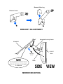
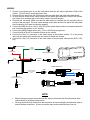
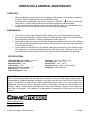
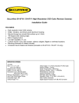
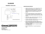
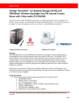
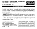
SV- 9155
4.2” Replacement
Rear View Mirror
Monitor
INSTALLATION INSTRUCTIONS:
The SV-9155 is a replacement Rear View Mirror. It replaces your factory mirror and adds the
convenience of a 4.2” LCD screen which can be used for a reverse and an external DVD
source. The Reverse Camera Input will automatically switch on when the vehicle is dropped into
reverse. The SV-9155 can be hooked up to any SecurView™ or PlateCam™ camera.
FEATURES:
•
•
•
•
•
•
•
•
•
•
•
Replacement Rear View Mirror with Built-In 4.2” LCD Screen for viewing Reverse
Camera
Compatible with any Camera which uses an RCA video output
Provides extra safety precaution when backing-up
Maintains the “Factory” look of the vehicle
Optional Normal Image and Reverse Image
Compatible with 70%-80% of GM, Ford and Toyota vehicles.
Compatible with 12V and 24V DC vehicles
Built-In Interface to allow user to switch between to different video inputs
High-Low voltage and short circuit protection
Reverse camera input will appear on screen whenever vehicle is shifted into reverse
Anti-Glaring treatment on Screen
INSTALLATION
INSTALLATION PRECAUTIONS:
1. Secure the mirror tightly to the windshield so that it can not become loose under any
circumstances (Sudden braking, accidents, etc) and cause injuries to the occupants of the
vehicle.
2. Do not install the mirror in an area that is in close proximity with an airbag, as this could cause
injury if the airbags are deployed.
3. Make sure to connect the mirror to the correct voltage. Failure to do so may result in damage
to the mirror or injury to the vehicle occupants
4. Do not submerge the mirror under water. The mirror is not waterproof and this will damage
the electrical components inside of it.
5. The Mirror has built-in circuitry to reverse the image so objects on the right of vehicle appear
on the right and objects on the left appear on the left when looking at the monitor. (See
Reverse Imaging in next section for more information.)
6. Do not attempt to take apart the mirror under any circumstances.
7. Do not operate the monitor if the mirror housing has been damaged.
MIRROR MONITOR INSTALLATION:
1. Remove the OEM Rear View Mirror from the vehicle. Usually the OEM mirror should unscrew
from a mounting plate on the vehicle’s windshield. Do not use excessive force when removing
the factory mirror.
2. Some factory rear view mirrors may have “Reading Lamps” or “Map Lights” built into them. In
order to remove this type of mirror, there will be a wiring harness that will need to be
unclipped before you can proceed with the removal of the mirror itself. Make sure the vehicle
owner is aware that the SV-9155 does not have any lamps built into it and that they will be
losing this accessory once the factory mirror is removed.
3. Once the factory mirror is removed, place the SV-9155 into the position of where the factory
mirror was located for a fest fit.
4. Adjust the angle of the SV-9155 to the best position by rotating the ball-joint of the adjustable
mounting bracket on the back of the mirror.
5. Remove the screw and silver lug form the base of the SV-9155 mounting bracket.
6. Slide SV-9155 Mounting Bracket over the factory mounting plate on the windshield.
7. Make sure that the mounting bracket fits over the entire windshield mounting plate.
8. Re-insert the screw into the mounting bracket and secure the mirror tightly over the factory
mounting plate.
9. DO NOT overturn the mounting screw. This will cause the screw’s threads to strip and may
also damage the threads inside the mounting bracket itself.
10. Route the electrical cable of the SV-9155 up the windshield and underneath the headliner of
the vehicle
NOTE:
The holes in the back and the bottom of the unit are provided for ventilation to prevent
overheating of the unit and to ensure reliable operation of the monitor equipment. These holes
must not be blocked with any kind of electrical tape or silicon. If the ventilation holes are
blocked, this could cause damage to the monitor
Remove Silver Lug
Remove Screw
BRACKET ADJUSTMENT
Adjustable Mounting Bracket
Windshield
SV-9155
Mirror
Mounting
Screw
NOTE
Cable
Mounting Bracket of SV-9155 should
slide over the factory mounting plate
on windshield
SIDE VIEW
MIRROR MOUNTING
WIRING:
1. Choose a convenient place to run the cable either down the left side or right side A-Pillar of the
vehicle. (The left side is usually the easier side)
2. Remove the trim panel from the A-Pillar and route the cable down the pillar to the dash board.
3. In most vehicles, there will be a wire harness for the dome light inside the A-Pillar of the vehicle.
Use a wire tie or electrical tape to secure the cable to this wire harness.
4. Re-Install the trim panel. Make sure that the cable does not interfere with the mounting clips or
screws of the trim panel. This may cause damage to the cable and the trim panel and may cause
the trim panel to not fit back into position properly.
5. Connect the RED wire to a +12V or +24V DC Ignition power terminal which is energized when the
key is turned to the Ignition or “On” position.
6. Connect the GREEN trigger wire to the +12V or +24V Reverse Light wire.
7. Connect the BLACK wire to a suitable Ground on the vehicle.
8. Connect the Grey (V1) connector to the video output of the reverse camera. V1 is the priority
input and will always auto switch when the vehicle is shifted into reverse.
9. Connect the Grey (V2) connector to the video output of any external video device (DVD, VCR,
etc)
VEHICLE IGNITION
GREEN
+12V Reverse
Light
RED
+12V Switched IGN On
VEHICLE REVERSE LIGHT
SV-9155 MIRROR
10' LENGTH
CABLE
BLACK
Chassis Ground
VIDEO ADAPTER PLUG
CAM 1
Audio Inputs (NOT USED)
V1 Reverse Image Input
Connect to Reverse
Camera
V2 Normal Image Input
Connect to External Video Source
Camera
Power Plug
YELLOW
RCA Video Output
CAM 2
REVERSE CAMERA
NOTE
•
•
Before making any power connections to the vehicle, disconnect the Ground terminal of the
vehicle battery to avoid any short circuits
All plugs should be fully inserted into the connectors and secured tightly with electrical tape to
assure the best connection. A loose connection may cause malfunctioning of the unit
MONITOR CONTROLS
Menu
_
CAM Select /
+
MONITOR CONTROLS:
1. CAM SEL /
This button combines two function. Press this button to toggle between the
VI and V2 Inputs. Press and hold it for 2 seconds to turn off the power to the monitor. This will
put the monitor into “Standby” mode. Press it again to turn the power back on.
2. MENU
• CONTRAST CONTROL: To adjust the contrast of the screen, Press the “MENU” button
and then select CONTRAST on the screen. Use the + and – buttons to increase or
decrease the picture contrast.
• BRIGHTNESS CONTROL: To adjust the brightness of the screen, Press the “MENU”
button and select BRIGHTNESS on the screen. Use the + and – buttons to increase or
decrease the brightness of the monitor.
• COLOR CONTROL: To adjust the color of the screen, Press the “MENU” button and
select COLOR on the screen. Use the + and – buttons to increase or decrease the color
contrast of the screen.
• NORMAL / MIRROR IMAGE: Some reverse cameras have built-in circuitry to “mirror”
the image so objects on the right of vehicle appear on the right and objects on the left
appear on the left when looking at a standard monitor. If your camera does not have this
function, then you can choose it in the SV-9155 menu. You can set Normal/Mirror imaging
for CAM1 and CAM2 separately. To adjust, Press the “MENU” button and select MIR1
OFF on the screen. Press the + and – buttons to set the screen to Mirror or Normal
Image on CAM1. You can set the CAM2 image the same way.
• PARKING ASSIST: This can help the user to properly judge distance when parking.
Press the “MENU” button, and choose DASH (ON) on the screen. Use the + and –
buttons to activate. The parking assist line only appears when the vehicle is in reverse. At
this time, the dash can be adjusted horizontally by pressing the + or – buttons. Adjust the
line to the appropriate position for your actual parking condition. Once this is done, the
setting will be locked in memory.
OPERATION & GENERAL MAINTENANCE
OPERATION:
•
•
When the Ignition key is turned to the Accessory or ON position, +12V power is supplied to
the mirror. The front LED light will turn on solid RED in color.
No Image will be displayed on the monitor. Press the “CAM SEL /
“ button to activate the
video inputs. Or simply shift the vehicle into reverse to engage the reverse camera.
If your vehicle has been parked in direct sun light, this can result in a considerable rise in
temperature inside the vehicle. Allow the unit to cool off before operating
MAINTENANCE:
•
•
•
•
Clean the unit with a slightly damp soft cloth. (Make sure to turn Power off before cleaning)
Do not use liquid cleaners or aerosol cleaners to clean the mirror. Never use strong solvents
such as thinners or benzene. These may damage the finish of the unit.
Never poke or push any objects of any kind through the ventilation holes of the unit. Objects
may touch the electronic components inside the unit causing it to short-circuit and could result
in a fire or electric shock.
Do not attempt to service this unit by yourself. Opening or removing any of the outside covers
will expose you to electrical components which may cause injury. Opening of any of the
covers will also void the warranty of the mirror. Refer to an authorized dealer for servicing.
SPECIFICATIONS:
LCD Profile Wide Screen Ratio: 16:9 (4.2”)
View Angle (U/D/L/R): 25/45/45/45
Brightness (cd/m²): 200
Contrast Ratio: 400:1
Response Time (in ms at 25°C): 15
Power Supply: 12V / 24V DC
Power Consumption: <7W
Resolution: 320(V) × 234(H) TV Lines
Operating Temp: -20C - +70°C
Storage Temp: -30°C - +80°C
Dimensions (mm): 280(L) × 91(W) × 30(D)
Weight (Oz): 490 with bracket
DISCLAIMER:
Under no circumstances shall the manufacturer or distributor of the SV-9155 Mirror be held liable for
consequential or incidental damages sustained in connection with the use of the SV-9155 Rear Vision
System. The SV-9155 is designed as a safety enhancement device and is in no way intended as a
replacement for rear-view mirrors, side-view mirrors or physically checking the surroundings when
backing a vehicle. Always check surroundings for safety when backing! Objects on the monitor are
closer than they appear. Any changes or modifications in construction of this device will void the
warranty.
www.crimestopper.com
[email protected]
Phone (800) 998-6880
FAX (805) 581-9500
© 2009 Crimestopper Security Products
5-12-2009