1
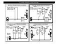
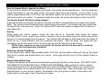
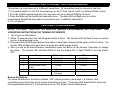
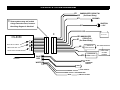
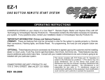
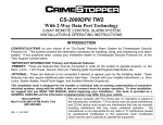
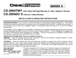
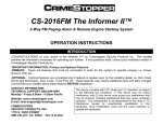
CS-8050
HANDS-FREE KEYLESS ENTRY / IMMOBILIZER SYSTEM
INSTALLATION & OPERATING INSTRUCTIONS
INTRODUCTION
CONGRATULATIONS on your choice of a Hands-Free Keyless Entry & Immobilizer System by Crimestopper
Security Products Inc. This booklet contains the information necessary for installing, using, and maintaining
your alarm system. If any questions arise, contact your installation dealer or Crimestopper Security Products
Inc. at the Tech Support number below.
*IMPORTANT INFORMATION: Primary and Optional Features:
-PRIMARY: These are features that must be connected in order for the system to operate properly; i.e. the
+12V Power, Ground, Ignition, LED, Override/Program/Valet Button etc.
-OPTIONAL: These are features to be connected if desired or agreed upon by the installing dealer. These
features may also require additional parts and/or labor fees. Consult with your installer beforehand; i.e.
Domelight Illumination, Armed Output etc.
TECH SUPPORT
Mon-Fri 8:00 AM-4:30 PM Pacific Time
(800) 998-6880
REV. C 5/2002 SW: IC
This device complies with FCC Rules part 15. Operation is subject to the
following two conditions: 1) This device may not cause interference, and (2)
this device must accept any interference that may be received, including
interference that may cause undesired operation. The manufacturer is not
responsible for any radio or TV interference caused by unauthorized
modification to this equipment. Such modification could void the user's
authority to operate the equipment.
INSTALLATION PRECAUTIONS & WARNINGS
BEFORE BEGINNING, check all vehicle manufacturer cautions and warnings regarding electrical service (AIR
BAGS, ABS BRAKES, AND BATTERY).
DO NOT ROUTE ANY WIRING THAT MAY BECOME ENTANGLED with brake, and gas pedals, steering
column, or any other moving parts in the vehicle.
COMPONENT MOUNTING
Control Unit: DO NOT mount or wiring harness where they can become entangled with moving parts such as
brake/gas/clutch pedals, or the steering column! The alarm control module should be mounted in a concealed
location. Do not mount the control unit in the engine compartment. The antenna wire should be routed away
from any metal if possible. Do not alter the length of the antenna wire or ground the antenna wire.
LED: Mount in a visible location on the dashboard or console.
Valet/Program Button: Mount button in a hidden but accessible location. It is REQUIRED for emergency
disarm, programming, and valet mode.
WIRING
Note: This unit includes High-Security wiring with the critical connection wires being the same BLACK
color to deter or confuse someone from tampering with this unit. Please match the appropriate wire
number with the number on the diagram for proper connection. DIAGRAM : PAGE 8
WIRE #1: Immobilizer Circuit #2 Output:
This is part of the immobilizer circuit (on-board relay). Cut the Starter wire and connect ONE end to this wire.
WIRE #2: Immobilizer #2 Input:
This is part of the immobilizer circuit (on-board relay). Connect the other end of the Starter wire to this wire.
WIRE #3: Chassis Ground:
This wire must be connected to chassis metal of vehicle. Use a sheet metal screw and star washer to insure a
good connection. Keep the ground wire short and try not to use factory ground locations.
WIRE #4: Ignition Switched "ON" and "START" +12Volts:
Connect to an Ignition Wire (or fuse in the fuse box) that shows +12 Volts Power when the key is in "ON" and
"START" (cranking) position.
WIRING
WIRE #5: +12Volt Power Input:
Connect to Battery Positive Terminal.
WIRE #6: Immobilizer Circuit #1 Output:
This is part of the immobilizer circuit (on-board relay). Cut the Ignition wire and connect ONE end to this wire.
WIRE #7: Immobilizer #1 Input:
This is part of the immobilizer circuit (on-board relay). Connect the other end of the Ignition wire to this wire.
WIRE #8: (-) Horn Honk Output (Optional, may require relay):
Connects to (-) Negative Horn activation circuit on vehicle to honk vehicle’s horn when the system is triggered.
If the vehicle has a +12V positive horn circuit, then a relay is required. Connect to terminal 85 of a relay.
Connect terminals 86 & 87 to +12V Constant Power. Connect terminal 30 to the Positive horn activation
circuit.
WIRE #9: (-) Neg. Dome Light Illumination or Factory Disarm Output (Optional, requires relay):
This output can be programmed to turn on the Domelight for 30 seconds upon disarming for illuminated entry
at night, or to be a .5 Second negative disarm pulse for Factory Alarm system. When used a Domelight
output, a relay is required: Connect the #9 wire to terminal 85 of a relay. Connect terminal 86 to +12V
Constant. Connect terminal 87 to +12V or Ground depending on the type of dome light circuit in the vehicle.
Connect terminal 30 to the dome light circuit.
WIRE #10: (-) Negative Armed Output (Optional):
Provide (-) 500mA output when armed. This wire can be used to add an additional Immobilizer Circuit or other
accessory such as scanner type LEDs or window roll up modules (not included).
MINI PLUGS: LED / VALET-PROGRAMMING SWITCH / DOOR LOCKS
Mount the LED in a visible location, then connect 2-pin Red plug to the Red Connector on the module
Mount the Override/Valet button and connect 2-pin Blue plug to the Blue connector on the module.
Blue Wire: (-) Negative Door Unlock Output
Red Wire (+) +12Volts Constant Output: Connect to terminal 86 (relay coil power) of Aftermarket relay for
activating positive, reverse polarity, and after market door locking systems.
Green Wire: (-) Negative Door Lock Output
POWER DOOR LOCK WIRING
NEGATIVE TRIGGER DOORLOCK WIRING
POSITIVE TRIGGER DOORLOCK WIRING
GREEN
GREEN
RED
RED
BLUE
BLUE
FUSED
+12V
+
85
86
87
87A 30
FACTORY
POWER
LOCKING
RELAYS
L
UL
REVERSE POLARITY DOOR LOCK WIRING
GREEN
FUSED
+12V
+
RED
BLUE
85
86
87
87A 30
85
86
87
87A 30
MASTER
SWITCH
+
L
UL
CUT
CUT
85
86
87
87A 30
FACTORY
POWER
LOCKING
L
UL
RELAYS
ACTUATOR DOOR LOCK WIRING
GREEN
RED
FUSED
+12V
+
BLUE
85
86
87
87A 30
85
86
87
87A 30
OPERATING INSTRUCTIONS
How the System Works: (Hands-Free Mode)
As you turn your Ignition OFF and leave your vehicle, the system will automatically arm. The tiny hands-free
remote transmitter on your key chain emits a low power signal every few seconds. As you return to your
vehicle (approximately within 15-30 feet), the immobilizer system will “pick up” the signal from the tiny remote
and disarm/unlock your vehicle. To operate in hands-free mode, the remote transmitter must be turned ON.
Turning the Remote ON (Start sending signals):
Press and hold the remote button for about 5 seconds until LED on remote flashes once (Ignore first double
flash). The remote is now ON and will send a signal every few seconds. If you remain near your vehicle with
the remote arm is will never arm. (Note: The remote is OFF when this system is shipped from the factory to
save battery life.)
Arming:
When exiting the vehicle, (Ignition turned off) there will be a 15-second delay before the system
AUTOMATICALLY arms. Again if your remote is turned on and you are within range your vehicle may not arm
because it is receiving signal from the remote. The In-Dash LED will begin to flash rapidly after the Ignition is
turned off as a visual indication that the countdown has begun. After the delay, the system will arm.
Immobilizer circuits will become active, the doors will lock and the LED will now flash slowly.
NOTE: If your remain in or near your vehicle, the system will not arm because it is receiving
signals from the hands-free transmitter.
Disarming: (Hands Free Mode)
As you return to your vehicle (approximately within 15-30 feet), the immobilizer system will “pick up” the signal
from the tiny remote and disarm/unlock your vehicle. Dome light will also turn on if this optional feature is
installed.
Manual Arming/Disarming:
If desired, this system can be armed and disarmed by pressing the button on the remote. YOU MUST HAVE
THE REMOTE OFF WHEN MANUALLY ARMING AND DISARMING. When exiting the vehicle, (Ignition
turned off) there will be a 15-second delay before the system AUTOMATICALLY arms or you can arm it by
pressing the button on the remote before the 15 second countdown ends. When returning to your vehicle
press the button on your remote to disarm. Remember to turn your ignition on within 15 seconds or the
system will try to arm again. See “Active Re-arm” below
ORERATING INSTRUCTIONS
Turning the Remote OFF (Stop sending signals):
Press and hold the remote button for 5 seconds until LED on remote flashes twice (Ignore first single flash).
The remote is now OFF and will not send signals. When you are going to be away from your vehicle for
extended periods of time, it is advisable to turn the remote off to save its battery life. However before you
return to your car, you must re-activate the remote or press the button using it manually.
Remote Status: ON or OFF? (How to check it):
Press the button on the remote and observe the LED. If it flashes ONCE, then it is on, or if the remote flashes
TWICE it is OFF. You can perform this simple check at anytime to check the status of the remote.
Active Re-Arming:
Once the system is disarmed, it will automatically re-arm itself after 30 seconds unless the Ignition is turned
on.
Alarm System Trigger:
Once the system is armed, it will trigger if an attempt is made to turn the Ignition ON or “Hot-Wire” the vehicle.
The horn will honk for a 30-second duration and will automatically reset if no further attempts are made.
NOTE: This is an immobilizer only, therefore it WONT: warn away, trigger upon door opening, or utilize
a siren.
Care of the Remote:
You should care for your hands-free remote transmitter just as you would for an alarm system remote control.
Do not submerge the remote in water or subject it to severe abuse.
Valet Mode:
Your CS-8050 system can be temporarily disabled from automatically arming for vehicle servicing or valet
parking. Turn the key on, then press and hold the Valet button for 5 seconds to put the system into Valet
mode. Repeat this procedure to exit the Valet mode. Once the system is in the Valet mode, the LED will stay
on when the Ignition is turned on and it will flash when the Ignition is off. The system will still arm/disarm
manually with the remote button during valet.
Emergency Override:
If you lose your remote or it becomes damaged and your immobilizer system is armed, you must perform an
Emergency Disarm in order to operate your vehicle. Turn the key on, then press and hold the Valet button for
10 seconds to disarm.
HANDS-FREE TRANSMITTER PROGRAMMING
This system can code learn up to 4 different transmitters. All transmitters must be learned at one time.
1. Turn ignition switch on and off 3 times leaving it on the 3rd time. (on/off, on/off, on) LED will Flash 3 times.
2. Push the Valet/Programming button for 5 seconds until the in-dash LED flashes 5 times.
3. Press the Button on the hands-free transmitter once – The dash LED will flash once to confirm
programming. Repeat this step within 5 seconds for up to 3 additional transmitters.
4. Turn off ignition.
FEATURE PROGRAMMING
NOTE!: YOU MUST TURN OFF ALL REMOTES BERORE PROGRAMMING ANY FEATURES!
OPERATION INSTRUCTIONS FOR TURNING OFF REMOTE.
SEE
1. Turn Key to the ON position
2. Within 10 seconds press the Valet/Program button 5 times. The System LED will flash 3 times to confirm
you are in programming mode.
3. Now press the Valet/Program Button the number of times that corresponds the option in the list below. The
System LED will flash once each time you press the Valet/Program button.
4. Once you are at the desired feature, momentarily press the Button on the Remote Transmitter to change
the option. The System LED will flash ONCE to turn the feature ON, or flash TWICE to turn the feature
OFF.
Feature
1.
2.
3.
4.
5.
6.
Feature Description
Auto Lock With Ignition
Unlock when disarmed
Horn Chirp for Arm/Disarm
Single/Double Unlock
Pulse
1 or 3 Second Lock Pulse
Wire #9 Function
ON (Default)
ENABLED
ENABLED
DISABLED
1 Pulse
LED
1
1
1
1
OFF
DISABLED
DISABLED
ENABLED
2 Pulses
LED
2
2
2
2
1 Second
30 Sec
Domelight
1
1
3 Second
Factory Disarm
2
2
Restore All Options:
To restore all features to the Factory Default (“ON” column) position, follow steps 1 & 2 above, then
immediately press the button on the remote transmitter one time. The system LED should flash 4 times and
the programmable features 1-6 will operate as in the “ON” default column listed above.
CS-8050 SYSTEM DIAGRAM
#1
#2
IMMOBILIZER CIRCUIT #1
(On Board Relay)
#3
systems may not include
* Some
a large connector here, however
GROUND
IGNITION
+12V
#4
the wiring diagram is identical.
#5
+
*
CS-8050
#6 IMMOBILIZER
CIRCUIT #2
#7 (On Board Relay)
BLUE PLUG: VALET
#8
RED PLUG: LED
WHITE PLUG: DOOR LOCKS
(-) NEGATIVE
HORN OUTPUT
#9
#10
BLUE
ANTENNA
-
BATTERY
(-) NEGATIVE
ARMED OUTPUT
RED
VALET/
PROGRAM
SWITCH
WHITE
LED
GREEN
RED
BLUE
(-) LOCK OUTPUT
+12V FOR RELAYS
(-) UNLOCK OUTPUT
MAY REQUIRE RELAY
(-) NEG. DOME
OR OEM
DISARM