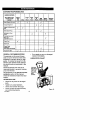
1
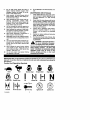
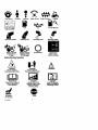
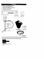
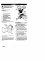
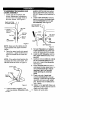
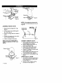
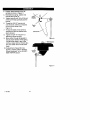
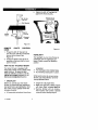
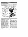
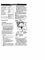
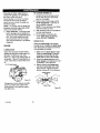
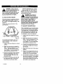
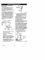
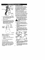
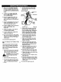
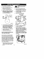
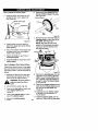
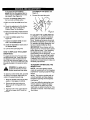
a
a
0
ll
a
11.0 Horsepower
30 Inch Dual Stage
120V, Electric Start
SNOW THROWER
MODEL NO.
536.881130
Caution:
Read and follow all Safety Rules
and Operating Instructions before
first use of this product.
SEARS,
F-001060J
ROEBUCK
08/25/99
AND CO., Hoffman
Estates,
g
IL 60179 U.S.A.
I
i_'_Jnl= L'_J_Ko]LrI_;I_ii_"]
WARRANTY STATEMENT
......
SAFETY RULES ...............
INTERNATIONAL SYMBOLS ....
ASSEMBLY ...................
OPERATION
..................
MAINTENANCE
...............
SERVICE AND ADJUSTMENT ...
LIMITED TWO-YEAR
2
2
4
6
STORAGE
....................
TROUBLE SHOOTING CHART
REPAIR PARTS ................
ENGINE REPAIR PARTS ........
11
17
20
WARRANTY
..
28
29
30
46
SPANISH (ESPAI;IOL) ..........
55
PARTS ORDERING/SERVICE
..
BACK COVER
ON CRAFTSMAN
SNOW THROWER
For two years from the date of purchase, when this Craftsman Snow thrower is madntained,
lubricated, and tuned up according to the operating and maintenance instructions in the
owner's manual, Craftsman will repair, free of charge, any defect in material or workmanship.
If this Craftsman Snow thrower is used for commercial or rental purposes, this warranty applies for only 90 days from the date of purchase.
This warranty does not cover the following:
Items which become worn dudng normal use, such as spark plugs, drive belts and shear
pins.
Repair necessaP/because of operator abuse or negligence, including bent crankshafts
and the failure to maintain the equipment according to the instructions contained in the
owner's manual.
WARRANTY SERVICE IS AVAILABLE BY RETURNING THE CRAFTSMAN
SNOW
THROWERTO THE NEAREST CRAFTSMAN
SERVICE CENTER/DEPARTMENT
IN
THE UNITED STATES. THIS WARRANTY APPLIES ONLY WHILE THIS PRODUCT IS
IN USE IN THE UNITED STATES.
This warranty gives you specific legal rights, and you may also have other rights which may
vary from state to state.
Sears, Roebuck and Co., D617WA,
,_
Hoffman Estates. IL 60179
IT
MEANS-ATTENTION!!!
ALERTI!!
YOUR SAFETY
IS INVOLVED.
LOOK
FOR THIS
SYMBOL TOBECOME
POINT OUT
IMPORTANT
SAFETY PRECAUTIONS.
the
spark
WARNING:
where It
with spark plug
starting
during:
nance, or Storage
plug
wire and
place it
Always
disconnect
cannot make contact
to prevent accidental
Preparation,
Mainteof you snow thrower.
IMPORTANT:
Safety standards require operator presence controls to minimize the risk of injury. Your snow thrower is equipped with such
controls. Do not attempt to defeat the function
F÷OO1060J
2
of the operatorpresencecontrolunderany circumstances.
7.
TRAINING
1.
Read the operating and service instruction
manual carefully. Be thoroughly familiar
with the controls and the proper use of the
equipment. Know how to stop the unit and
disengage the controls quickly.
2.
Never allow children to operate the equipmerit. Never allow adults to operate the
equipment without proper instruction.
3.
Keep the area of operation clear of all persons, padiculady small children and pets.
Exercise caution to avoid slipping or falling
especially when operating in reverse.
4.
8.
9.
Thoroughly inspect the area where the
equipment is to be used and remove all
doormats, sleds, boards, wires, and other
foreign objects.
2.
Disengage all clutches before starting the
engine (motor).
3.
Do not operate the equipment without
wearing adequate winter outer garments.
Wear footwear that will improve footing an
alippery surfaces.
4.
Handle fuel with care; it is highly flammable.
a,
Use an approved fuel container.
b.
Never remove fuel tank cap or add fuel
to a running engine (motor) or hot engine (motor).
c.
d.
Fill fuel tank outdoors with extreme
care. Never fill fuel tank indoors.
1.
2.
3.
4.
5.
6.
7.
Replace fuel cap securely and wipe up
spilled fuel.
Never store fuel or snow thrower with
8.
fuel in the tank inside of a building
where fumes may reach an open flame
or spark,
Check
lowing
of the
cause
fuel supply before each use, alspace for expansion as the heat
engine (motor) and/or sun can
fuel to expand.
5.
For all units with electric starting motors
use electric starting extension cords certified CSfVUL. Use only with a receptecle
that has been installed in accordance with
local inspection authorities.
6.
Adjust the snow thrower height to clear
gravel or crushed rock surface,
F-OOIO60J
Always wear safety glasses or eye shields
during operation or while performing an ad justment or repair to protect eyes from
foreign objects that may be thrown from the
snow thrower.
OPERATION
PREPARATION
1.
Never attempt to make any adjustments
while the engine (motor) is running (except
when specifically recommended by manufacturer).
Let engine (motor) and snow thrower adjust to outdoortemperatures before starting
to clear snow.
9.
10.
Do not operate this machine if you are taking drugs or other medication which can
cause drowsiness or affect your ability to
operate this machine.
Do nat use this mechine if you are mentally
or physically unable to operate this machine sefaly.
Do not put hands or feet near or under rotating parts. Keep clear of the discharge
opening at all times.
Exercise extreme caution when operating
on or crossing gravel drives, walks or
roads. Stay alert for hidden hazards or
traffic.
After striking a foreign object, stop the engine (motor), remove the wire from the
spark plug, thoroughly inspect snow
thrower for any damage, and repair the
damage before restarting and operating
the snow thrower.
If the unit should start to vibrate abnormally, stop the engine (motor) end check immediately for the cause. Vibration is
generally e warning of trouble.
Stop the engine (motor) whenever you
leave the operating position, before unclogging the auger/_mpallar housing or discharge chute and when making any
repairs, adjustments, or inspections.
When cleaning, repairing, or inspecting,
make certain the augar/impeller and all
moving parts have stopped and all controls
are disengaged. Disconnect the spark plug
wire and keep the wire away from the spark
plug to prevent accidental starting.
Take all possible precautions when leaving
the snow thrower unattended. Disengage
the auger/ impener, stop engine (motor),
and remove key.
Do not run the engine (motor) indoors, except when starting the engine (motor) and
for transporting the snow thrower in or out
of the building. Open the outside doors; exhaust fumes are dangerous (containing
CARBON MONOXIDE, an ODORLESS
and DEADLY GAS).
11.
12
t3.
Do not clear snow across the face of
slopes. Exercise extreme caution when
changing direction on slopes. Do net attempt to clear steep slopes,
Never operate the snow thrower without
proper guards, plates or other safety protective devices in place.
Never operate the snow thrower near enclosures, automobiles,
window wells,
droppers, and the like without proper adjustment of the snow discharge angle.
Keep children and pets away,
14.
Do not overload the machine capacity by
attempting to clear snow at too fast a rate,
15.
Never operate the machine at high transport speeds on slippery surfaces, Look behind and use care when backing up.
Never direct discharge at bystanders or
allow anyone in front of the unit.
16.
17,
Diseegage power to the colleetor/impeller
when snow thrower is transported or not in
use.
18.
Use only attachments and accessorias approved by the manufacturer of the snow
thrower (such as tire chains, electric start
kits, ect).
19.
Never operate the snow thrower without
good visibility or light. Always be sure of
your footing and keep a firm hold on the
handles, Walk;never run.
20.
Do not over-reach.
Keep proper footing
and balance at all times.
21.
Do not attempt to use snow thrower on a
roof.
MAINTENANCE
AND STORAGE
1.
Cheek shear bolts and other bolts at frequent intervals for proper tightness to be
sure the equipment is in safe working
condition,
2,
Never store the snow thrower with fuel in
the tank inside a building where ignition
sources are present such as hot water and
space heaters, clothes dryers, and the like.
Allow the engine (motor) to cool before
storing in any enclosure,
3.
Always refer to operator's guide instructions far important details if the snow
thrower is to be stored for an extended
peded.
4.
Maintain or replace safety and instruction
labels, as necessary.
Run the snow thrower e few minutes after
throwing snow to prevent freeze-op of the
anger/impeller.
5.
,_
for use on sidewalks,
WARNING:
This snow driveways
thrower is
and other ground level surfaces.
Caution should be exercised while using on
steep sloping surfaces.
DO NOT USE
SNOW THROWER ON SURFACES ABOVE
GROUND LEVEL such as roofs of residences, garages, porches or other such
structures or buildings.
IMPORTANT: Many of the following symbols are located on your unit or on literature supplied with the product. Before you operate the unit, learn and understand the purpose for
each symbol.
Control And Operating
Slow
Symbols
Fast
Electric Start
No
I
Engine Off
On
Engine Stop
Engine Start
Engine Run
H N
Choke Off
Choke On
Neutral
®@
Throttle
F-0OIOSOJ
Primer Button
Ignition Key
4
Ignition Off
Ignition On
DriveClutch Forward ReverseAuger
ClutchAuger
Collector Engage
PushToEngage
Electric
Starter
Fuel
O]1
FuelOIIMixture
f
Discharge
DOWN
Discharge
UP
Discharge
LEFT
Discharge
RIGHT
Edlmo]
Weight Transfer
Lift Handle To
Engage
Weight Transfer
Depress Pedal
To Disengage
Transmission
Ignition Key
Insert To Run,
Pull Out To Stop.
Safety Warning Symbols
DANGER
Thrown Objects.
Keep Bystanders Away.
DANGER
Thrown Objects.
Keep Bystanders Away.
IMPORTANT
Read Owner's Manual
Before Operating
This Machine.
DANGER
Avoid Injury From
Rotating Auger. Keep
Hands, Feet And
Clothing Away.
WARNING
Hot Surface
F-001060J
STOP
5
WARNING
DANGER
Stop The Engine
Before Unclogging
Discharge Chutel
Contents
of Parts Bag (actual size)
1 - Owner's Manual (not shown)
1 - Packet of Fuel Stabilizer (not shown)
1 - Warranty Card (not shown)
2 - Parts bags (not shown)
*Non-Assembly
Parts, found in toolbox located on belt cover
1- Screw, 3/8-16
x 2 in
1-Split
Lockwasher
©
1-Flatwasher
3/8 In.
1- Nut, 3/8 In.
2 - Shift Lever Knobs
(not actual size)
2 - 3/8
Hex Jam Nuts
C z'e'l
Parts packed separately in carton (not shown full size)
2- Ignition Keys
(Attached to engine
F-CO 1060J
in plastic
bag)
6
Auger
_lh
safety
ARNING:
glasses
Always
or eye
wear
shields
while assembling snow
thrower.
TOOLS REQUIRED
ASSEMBLY
Traction
Lever
Cable
Chute
Shifter
Lever
FOR
Chute
Deflector
1 - Knife to cut carton
t - 1/2 inch wrenches
(or adjustable wrenches)
1 - 9/16 inch wrenches
(or adjustable wrenches)
1 - 3/4 inch wrenches
(or adjustable wrenches)
1 - Pliers (to spread cotter pin)
1 - Screwdriver
Figure 2
t - Measuring tape or ruler
Figure 1 shows the snow thrower in the
shipping position.
TO REMOVE
SNOW
FROM CARTON
THROWER
t.
Locate all parts packed separately
and remove from the carton.
NOTE: Place fuel stabilizer in a safe
place until needed for storage.
2. Remove top pallet from carton.
3. Cut and discard the plastic ties securing the chute rod to the upper
pallet and place aside. Discard pallet.
4, Cut down all four corners of the carton and lay the panels flat.
5. Cutthe bands holding the snow
thrower to the lower pallet.
6. Remove snow thrower from lower
pallet.
7. Remove the packing material from
the handle assembly and all protective material from unit and discard,
Figure 1
Figure 2 shows the snow thrower completely assembled,
References to the right or left hand side
of the snow thrower are from the viewpoint of the operator's position behind
the unit.
F_301060J
8.
7
Cut ties securing the clutch control
cables to the lower handle.
TO ASSEMBLE
THE HANDLEAND
CRANK ASSEMBLY
t. Loosen, but do not remove, the
screws, flatwashers, Iockwashers,
and hex nuts in the upper holes of
the lower handle. See Figure 3.
washer, and hex nut) into bottom
hole on right hand side of handles.
DO NOT tighten until all bolts are in
place.
4. Locate crank assembly removed
earlier and remove the nylon locknut and flatwasher from the eye
bolt assembly. See Figure 5.
Right Hand Side
Of L
Left Hand Side Of
Upper Handle
3/8" Hex
Nut
Loosen,
but do not*,,
remove
3/8" Flat3/8" Nylon
, Locknut
Hex Nut,
3/8 x 2"
Screw
3/8"
3/8"
Figure 3
3/8" Flatwasher
NOTE: Make sure the cables are not
caught between the upper and lower
handle.
Figure 5
5.
Reinstall flatwasher and adaptor.
Install eye bolt through lower hole
on the left hand side of the handle.
6. Install the 3/8" flatwasher and the
3/8" nylon Iocknut loosely on the
eye bolt.
7. Carefully remove cotter pin, clevis
pin and universal joint pin from
yoke end of crank rod assembly.
See Figure 6.
8. Place universal joint into end of
worm gear lining up Large holes. Insert universal joint pin (ensure
opening in pin Is In line with
small openings In universal
2. Raise the upper handle into operating position. Upper handle should
be to the outside of the lower handie.
NOTE: Ifthe cables have become disconnected form the clutch levers, reinstall the cables as shown in Figure 4.
Clutch L_
Cont;cZ"IFitly,
joint).
J
9. Place yoke end of crank rod
around universal Joint, lining up
openings. Insert clevis pin through
assembly and secure with cotter
pin. Spread ends of cotter pin to
lock in place.
10. Tighten nut on eye bolt. Make sure
eye bolt is properly aligned and the
crank can freely rotate.
11. Tighten all handle bolts.
Cable _(_/
Figure 4
3.
Install hardware supplied in the
parts bag (screw, flatwasher, Iock-
F-O01060J
8
Chutein Operating __
CotterPin
Clevis Pin
Position
Crank Rod
Figure 8
Figure 6
NOTE: If the cables have become disconnected, reinstall springs as shown in
Figure 9.
ASSEMBLE SNOW CHUTE
1. Remove back carriage bolt. See
Figure 7.
TractionDrive
Spring(Long)
Auger Drive
I
Spring(Short ,_
_
2. Tilt chute back into operating position. See Figure 8.
3.
Replace carriage bolt from inside of
chute.
4.
Replace fiat washer and nylon locknut on outside of flange.
5.
Tighten carriage bolt securely.
I'
NOTE: Check all carriage bolts in
flange for tightness. DO NOT overtighten.
CONNECT
\
F-OOIO60J
Figure9
CHUTE
Push remote chute control lever into
"Chute Deflector Up" position.
2. Feed "Z" fitting through hole in remote chute bracket. See.
Snap remote chute control cable
into remote chute bracket. See.
4.
Connect "Z" fitting into remote chute
control bracket. See.
5. Push remote chute control lever into
"Chute Deflector Down" position.
6. Cut tie strap on chute deflector. See
Figure.
SPEED
Carriage
Remow
REMOTE
--
1.
3.
Shipping Position
'
Figure 7
SELECT
LEVER
1. Cut plastic tie securing speed select
lever assembly to the shifter bracket. See Figure 10.
2. Remove Iocknut, washer, spring,
and the bolt. See Figure 12.
3. Position
speedselector
lever
assembly as shown in Figure 11.
4. Reinstall bolt, spring, washer and
Iocknut See Figure 12.
5. Tighten Iocknut until 1/8 to 3/16 inch
of the bolt threads protrude pas the
Iocknut.
Shifter
Bracket
6.
Thread the 3/8-16" hex jam nut
onto the lever until the nut reaches
the end of the thread. See
Figure 12.
7. Thread the plastic knob as far as
possible and ensure that the knob
points forward.
8. Tighten the 3/8-16" hexjam nut
against the knob securely.
9. Move shifter through all speeds to
ensure proper tension of the spring.
If shifter lever sticks in any of the
notches, loosen Iocknut 1/2 turn at a
time until shifter lever moves more
freely.
10. If adjustment of speed of snow
blower is needed, refer to "Friction
Wheel Adjustment" in the ADJUSTMENT/REPAIR section.
Plastic
Tie
Figure 10
Control
Panel
Figure 11
F-OOIO60J
10
f!_.'x_*]
=1_I=] Ik'4
3. "Rghten the 3/8-16" hex jam nut
against the knob securely.
3/jSa-16 Hex
Remote Chute
Control Knob
m Nut
Washer
Locknut
Control
Panel
• Exposed
Thread
Figure 12
REMOTE
KNOB
CHUTE
CONTROL
Figure 13
1. Thread the 3/8-16" hex jam nut
onto the lever until the nut reaches
the end of the thread. See
Figure 13.
2, Thread the plastic knob as far as
possible and ensure that the knob
points forward.
HEADLIGHT
The headlight on your snow thrower is
positioned down for packaging purposes. Rotate upward for operating
position.
HOW TO SET THE SKID HEIGHT
Your snow thrower is equipped with
height adjust skids on the outside of the
auger housing. To adjust the skid
height for different conditions, see To
Adjust Skid Height paragraph in the
Service And Adjustment section.
completed.
P" The discharge chute rotates freely.
_" No remaining loose parts in carton.
While learning how to use your snow
thrower, pay extra attention to the following important items:
_" CHECKLIST
Before you operate your new snow
thrower, to ensure that you receive the
best performance and satisfaction from
this quality product, please review the
following checklist:
_" Engine oil is at proper level.
._" Make sure gas tank is filled properly
with clean, fresh, unleaded gasoline.
P" Become familiar with all controlstheir location and function. Operate
controls before starting engine.
P" All assembly instructions have been
F-001060J
11
bPj=l--Iri_l[i]_]
KNOW YOUR SNOW THROWER
READ THIS OWNER'S MANUAL AND SAFETY RULES BEFORE OPERATING
YOUR SNOW THROWER. Compare the illustrations with your SNOW THROWER
to familiarize yourseff with the location of various controls and adjustments. Save
this manual for future reference.
Electric
Start
Button
Auger.
Drive Lever
(right hand)
Lever
(left hand)
, Remote
Primer
Chute Control
Switch
Box
;rank
Assembly
Chute Deflector
Discharge
Chok_
Control
Throttle
Control
Recoil
Starter
Handle
Figure 14
Auger Drive Lever - Starts and stops
the auger and impeller (snow gathering
and throwing)
Traction Drive Lever - Propels the
snow thrower forward and in reverse.
Choke Control
engine.
Speed Shifter Lever - Selects the
speed of the snow thrower (6 speeds forward and 2 speeds reverse).
Crank Assembly - Changesthe direction
of snow throwingthrough the discharge chute.
Chute Deflector - Changes the distance
Remote Chute Control Lever - Push
forward to discharge snow high and far.
Pull remote lever back to discharge snow
down.
Primer Button - Injectsfuel directly into
the carburetor manifold for fast starts in
cold weather.
Throttle Control - Controls the engine
speed.
Electric Start Button - (If so equipped)
Usedto startthe engineusingthe 120V Edectnc starter.
the snow is thrown.
Discharge Chute - Changes the height
anddirectionthe snowis thrown.
Height Adjust Skid - Adjusts the ground
clearance of the auger housing.
Ignition Key - Must be inserted to start
the engine.
Recoil Starter Handle - Starts the engine manually.
F-OO1060J
- Used to start a cold
12
Shear Pin -Shear pins are designed to
break (to protect the machine) if an obiect becomes lodged in the auger housIng.
Toolbox -spare shear pins and spacers
are located in toolbox,
The operation of any snow thrower can
result in foreign objects being thrown
into the eyes, which can result in severe eye damage. Always wear safety
glasses or eye shields while operating
the snow thrower.
We recommend standard safety
glasses or a wide vision safety mask for
over your glasses.
the speed you desire by moving the
speed shifter lever left into the appropriate notches on the shift lever
plate:
Speeds 1,2 - Wet, Heavy
Speed 3 - Light
Speed 4 - Very Light
Speed 5,6 - Transport only
Engage the traction drive lever (left
hand). As the snow thrower starts
to move, maintain a firm hold on the
handles, and guide the snow thrower along the clearing path. Do not
attempt to push the snow thrower.
3. To move the snow thrower backward, move the speed shifter lever
right into first or second reverse and
engage the traction drive lever (left
hand).
IMPORTANT: Do not move the speed
shifter lever while the traction lever
is down.
2.
Manual
before
WARNING:
Readoperating
Owner's
machine. Never direct discharge toward bystanders stop the
engine before unclogging discharge
chute or auger housing and before
leaving the machine,
i_
TO STOP YOUR
SNOW
THROWER
1. To stop throwing snow, release the
auger drive lever. See Figure 14.
2. To stop the wheels, release the
traction drive lever,
3. To stop the engine, push the
throttle control lever to off and pull
out the ignition key.
TO THROW SNOW
1. Push down the auger driver lever
(right hand).
2. Release to stop throwing snow.
TO CONTROL
SNOW DISCHARGE
1, Turn the chute control rod to set the
direction of the snow throwing.
2. Loosen the wing knob on the chute
deflector and move the deflector to
set the distance. Move the deflector
(Up) for more distance, (Down) for
less distance. Then tighten the
wing knob (See Figure 15).
TO USE WHEEL LOCKOUT PIN
1, The left hand wheel is secured to
the axle with a klick pin. This unit
was shipped with this klick pin in the
locked position (through wheel
hole). See Figure 16,
Klick Pin
Locked
Figure 15
2-Wheel
Figure 16
HOW TO MOVE FORWARD
AND
BACKWARD
1. To shift, release the traction drive
lever (left hand) and move the
speed shifter lever to the speed you
desire. Ground speed is determined by snow conditions. Select
F-O010S0J
"__osition
Drive
2.
13
For ease of maneuverability in light
snow conditions, disconnect the
kllek pin from the wheel locked
position and push into the single
wheel drive position (unlocked axle
hole only). See Figure 17.
OII Fill C_t_p/Dipstick
ickPin
Unlocked
sition
Single Wheel Drive
Figure 17
NOTE: Make sure that the klick pin is
in the single wheel drive position of the
axle only and not through the locked
position.
5. Checktire pressure (14-17
pounds). Do not exceed maximum
amount of pressure.
dicates that Experiences
alcohol blended
WARNING:
Infuels (called gasohol or
those using ethanol or methanol)
can attract moisture which leads to
separation and formation of acids
during storage. Acidic gas can damage the fuel system of an engine
while In storage.
NOTE: To avoid engine problems, the
fuel system must be emptied before
storage for 30 days or longer. Start the
engine and let it run until the fuel lines
and carburetor are empty, Use the carburetor bowl drain to empty residual
gasoline from the float chamber. Use
fresh fuel next season. See the Storage section in this manual for additional
information.
i_
CHECK THE OIL"
NOTE: The engine was shipped from
the factory filled with oil. Check the level of the oil. Add oil as needed.
1. Make sure the unit is level.
NOTE: Do not check the level of the
oil while the engine runs.
if necessary, add oil until the oil
reaches the FULL mark on the oil fill
cap/dipstick (see Figure 18). Do not
add too much oil.
F-001060J
must be between
full and Add mark
Figure18
FILL GAS:
NOTICE:
ENGINES WHICH ARE
CERTIFIED TO COMPLY WITH CALIFORNIA AND US EPA EMISSION
REGULATIONS FOR ULGE ENGINES:
Are certified to operate on regular unleaded gasoline. Include the following
emission control system(s): EM, TWC
(If so equipped). Include any user adjustable features-therefore no other adjustments are needed.
3. Be sure that all fasteners are tight.
4. Make sure the height adjust skids
are properly adjusted. See To Adjust Skid Height paragraph in the
Service & Adjustments section of
this manual.
3.
_'),y
Tighten the fill cap/dipstick securely
each time you check the oil level,
NOTE: For extreme cold operating
conditions of 0°F and below, use a partial synthetic 0W30 motor oil for easier
starting.
NOTE: S.A.E. 5W30 motor oil may be
used to make starting easier in areas
where temperature is consistently 20°F.
or lower.
1. Before you service or start the engine, familiarize yourself with the
snow thrower. Be sure you understand the function and location of all
controls.
2. Check the tension of clutch cable
before starting the engine. See To
Adjust The Control Cable paragraph in the Service & Adjustments section of this manual.
Remove the oil fill cap/dipstick.
Check the oil.
NOTE: Oil level
4.
BEFORE STARTING THE ENGINE
2.
;.._:_/
14
inn the engine, be certain that you have
read the following information.
Never use engine or carburetor cleaner
products in the fuel tank or permanent
damage may occur.
1 Fill the fuel tank only with a fresh,
clean, unleaded regular, unleaded
premium, or reformulated automotive gasoline. DO NOT use leaded
gasoline. Make sure that the container you pour the gasoline from is
clean and free from rust or other foreign particles. Never use gasoline
that may be stale from long periods
of storage in the container.
_b
equipped with
three-wlra
WARNING:
Thea starter
Is
power cord and plug and Is
designed to operate on 120 volt AC
household current.It must be properly grounded at all times to avoid the
possibility of electrical shock which
may be Injurious to operator. Follow
all Instructions carefully as set forth
In the "To Start Engine" section. Determine that your house wiring Is a
three-wire grounded system. Ask a
licensed electrician If you are not
sure. If your house wire system Is
not a three-wire system, do not use
this electric starter under any conditions. If your system is grounded
and a thrae-hole receptacle is not
available at the point your starter will
normally be used, one should be
installed by a licensed electrician.
when connecting 120 volt AC "Power
Cord", always connect the cord to
the Switch Box" on the engine first,
then plug the other end into the
three-hole grounded receptacle.
When disconnecting "Power cord",
always unplug the end In the threehole grounded receptacle first.
COLD START
1. Be sure auger drive and traction
drive levers are in the disengaged
(RELEASED) position.
2. Move throttle controt to"FAST" position,
3. Remove the keys form the plastic
bag. Insert one key into ignition
slot. Make sure it snaps into place.
Do not turn key. Keep the second
key in a safe place.
4. Rotate choke knob clockwise to the
choke ON position.
5. Connect the power cord to the
switch box on the engine.
6. Plug other end of power cord into a
three-hole, grounded t 20 VOLT, AC
receptacle. (See WARNING in this
section).
,_
mable.
Always
use caution
ARNING:
Gasoline
is flamwhen handling or storing
gasoline.
Do not fill fuel tank while snow
thrower is running, when It Is hot, or
when snow thrower Is In an enclosed area.
Keep away from open flame or an
electrical spark and do not smoke
while filling the fuel tank.
Never fill the tank completely. Fill
the tank to within 1/4"-1/2" from the
top to provide space for expansion
of fuel.
Always fill fuel tank outdoors and
use a funnel or spout to prevent
spilling.
Make sure to wipe up any spilled
fuel before stating the engine.
Store gasoline In a clean, approved
container and keep the cap in place
on the container.
TO STOP
ENGINE
To stop engine, move the throttle control lever to "STOP" position and remove key. Keep the key in a safe
place. The engine will not start without
the key.
TO START ENGINE
(electric starter, if equipped)
Be sure that the engine has sufficient "
oil. The snow thrower engine is
equipped with a 120 volt A.C. electric
starter and recoil starter. Before startF-001060J
15
7.
Push the primer button while covering the vent hole as follows: Remove finger from primer button
between primes.
Do not prime if temperature above
50 ° F (10 ° C).
Push two time if temperature
F (10 = C) to 15°F (-10 = C).
is 50 °
Push four times if temperature is
below 15° F (-10 ° C).
8. Push down on the starter button
until the engine starts. Do not crank
for more than 10 seconds at a time.
This electric starter is thermally protected. If overheated it will stop automatically and can be restarted
only when it has cooled to a safe
temperature (a wait of about 5 to 10
minutes is required).
9. When the engine starts, release the
starter button and move choke lever to "1/2 choke" position. When
engine runs smoothly, move choke
lever to "No Choke" Position.
10. Disconnect power cord from receptacle, first, and then from switch
box.
NOTE: Allow the engine to warm up for
several minutes before blowing snow in
temperatures below 0°F.
11, Run engine at full throttle "FAST'
when throwing snow.
WARM START
ff restarting a warm engine afier a short
shutdown, leave choke at "OFF" and do
not push the primer button, If the engine fails to start, follow the Cold Start
instructions.
COLD START
1, Be sure auger drive and traction
drive levers are in the disengaged
(RELEASED) position,
2. Move throttle control to"FAST' position.
3. Remove the keys form the plastic
bag. Insert one key Into ignition
slot. Make sure it snaps into place.
Do not turn key. Keep the second
key in a safe place.
4. Rotate choke knob clockwise to the
choke ON position.
5. Push the primer button while covering the vent hole as follows: Remove finger from primer button
between primes.
Do not prime if temperature above
50 ° F (10° (3).
Push two time if temperature is 50 °
F (10 ° C) to 15°F (-10 ° C).
Push four times if temperature is
below 15 ° F (-10 ° C).
6. Pull the starter handle rapidly. Do
not allow the handle to snap back,
but allow it to rewind slowly while
keeping a firm hold on the starter
handle.
7. As the engine warms up, move
choke lever to "1/2 choke" position.
When engine runs smoothly, move
choke lever to "No Choke" Position.
NOTE: Allow the engine to warm up for
several minutes before blowing snow in
temperatures below OoF.
8. Run engine at full throttle "FAST'
when throwing snow.
WARM START
If restarting a warm engine after a short
shutdown, leave choke at "OFF" end do
not push the primer button. Ifthe engine fails to start, follow the Cold Start
instructions.
TO START ENGINE
(recoil
starter)
Be sure that the engine has sufficient
oil. The snow thrower engine is
equipped with a recoil starter. Before
starting the engine, be certain that you
have read the following information.
F-0010SOJ
FROZEN STARTER
If the starter is frozen and will not turn
engine:
1. Pull as much rope out of the starter
as possible.
16
2.
Release the starter handle and let it
snap back against the starter.
If the engine still fails to start, repeat the
two previous steps until the engine
starts. Then continue with the directions for cold start.
Disconnect spark plug wire.
Do not place your hands in the
auger or discharge chute. Use s
pry bar.
SNOW THROWING
TIPS
1. For maximum snow thrower efficiency in removing snow, adjust ground
speed, NEVER the throttle. Go
slower in deep, freezing or wet
snow. Ifthe wheels slips, reduce
forward speed. The engine is designed to deliver maximum performance at full throttle and should be
run at this power setting at all times.
2. Most efficient snow throwing is accomplished when the snow is removed immediately after if falls.
3. For complete snow removal, slightly
overlap each path previously taken.
4. The snow should be discharged
down wind whenever possible.
5. For normal usage, set the skids so
that the scraper bar is 1/8" above
the skids. For extremely hardpacked snow surfaces, adjust the
skids upward so that the scraper
bar touches the ground.
6. On gravel or crushed rock surfaces,
set the skids at 1-1/4" below the
scraper bar. See To Adjust Skid
Height paragraph in the Service &
Adjustments section of this manual. Rocks and gravel must not be
picked up and thrown by the machine.
To help prevent possible freeze-up of
recoil starter and engine controls, proceed as follows after each snow removal job.
1. With the engine running, pull the
starter rope hard with a continuous
full arm stroke three or four times.
Pulling of starter rope will produce a
loud clattering sound. This is not
harmful to the engine or starter.
2. With the engine not running, wipe all
snow and moisture from the carburetor cover in area of control levers.
Also move throttle control, choke
control, and starter handle several
times.
gine
indoorsNever
or in run
enclosed,
WARNING:
enpoorly ventilated areas. Engine exhaust contains CARBON
MONOXIDE, AN ODORLESS AND
DEADLY GAS. Keep hands, feet,
hair and loose clothing away from
any moving parts on engine and
snow thrower.
The temperature of muffler and
nearby areas may exceed 150°F.
Avoid these areas.
DO NOT allow children or young
teenagers to operate or be near
snow thrower while It Is operating.
,_
7.
After the snow throwing job has
been completed, allow the engine to
idle for a few minutes, which will
melt snow and accumulated ice off
the engine.
8. Clean the snow thrower thoroughly
after each use.
9. Remove ice and snow accumulation
and all debris from the entire snow
thrower, and flush with water (if possible) to remove all salt or other
chemicals. Wipe snow thrower dry.
to ARNING:
remove any
that may
Do Item
not attempt
become lodged in auger
without taking the following precautions:
Release auger drive lever.
Move throttle lever to stop position.
_b
Remove (do not turn) Ignition
key.
F-OO_O60J
17
CUSTOMER
RESPONSIBILITIES
SERVICE RECORDS
Fill in dates as you
complete regular
service.
Before
Each
Use
Check Engine Oil Level
_/
Often
Every
5
Hours
Every
10
Hours
_/
_
Each
Season
Belore
Storage
_/
_/
_/
_/
_/
Check Spark Plug
Lubricate All Pivot
Points
_/
3'/
Lubricate Oisc Drive
Plate Zerk
See Maintenance)
Check Fuel
SERVICE
DATES
_/
Change Engine Oil
Tighten All Screws and
Nuts
Every
25
Hours
_/
_/
Drain Fuel
Check Cable
Ad ustment
(See Cable Ad ustment)
Adjust Drive Belt
_/
V
_/
GENERAL RECOMMENDATIONS
If any parts are worn or damaged,
replace immediately.
The warranty on this snow thrower
does not cover items that have been
subjected to operator abuse or negligence. To receive full value from the
warranty, the operator must maintain
the snow thrower as instructed in this
manual.
LUBRICATION
CHART
Lubricate
Disc Drive
Plate Zerk
With a Hi
Tem
Moly
Grease.
Some adjustments will need to be
made periodically to properly maintain
your snow thrower.
All adjustments in the Service and Adjustments section of this manual
should be checked at least once each
season.
AFTER EACH USE
Check for any loose or damaged
parts.
Tighten any loose fasteners.
Check and maintain the auger.
Check controls to make sure they
are functioning properly.
F-O0106OJ
Figure 19
18
PRODUCT SPECIFICATIONS
HORSEPOWER
11.0 HP
DISPLACEMENT
21.82 cu, in.
GASOLINE
CAPACITY
4 quads
(unleaded)
OIL CAPACITY
(20 oz capacity)
5W30
;PARK PLUG:
VALVE CLEARANCE:
prevent rubber friction wheel contacting the drive disc plate.
6. To grease zerk, use a hand grease
gun, lubricate with a Hi Temp EP
Moly grease. Fill zerk only until
grease becomes visible below bearing assembly located under grease
zerk. DO NOT over fill.
CAUTION: DO NOT allow grease to
come in contract with the disc drive
plate or friction wheel or damage will
result.
IMPORTANT: Remove coin and ensure that a gap exists between friction
wheel and disc drive plate.
NOTE: Clean all excess grease found
on friction disc hub.
Champion RJ19LM
(Gap .030 in.) or
equivalent
Intake: .010 In,
Exhaust: .010 In.
Sprockets
(Require No
Lubrication
SNOW THROWER
Hex Shaft and Sprockets
AS REQUIRED
Friction
The following adjustment should be
preformed more than once each season.
I. Auger drivebeltshould be adjusted
afterthefirst
2 to 4 hours of use,
again about mid-season and twice
each season thereafter
(See to AdjustBelts paragraph in the Service and Adjustment section).
LUBRICATION-EVERY
Disc
Drive
Plate
25 HOURS
Friction
Wheel
Lubricate Disc Drive Plate every
twenty-five (25) hours and at the end of
the season and/or before storage.
y.,,_oin
To Lubricate
1.
2,
3.
4.
5,
Position speed selector lever in first
gear,
Stand the snow thrower up on the
auger housing end.
Remove the bottom panel,
Turn disc drive plate clockwise by
hand until grease zerk is clearly
visible at front center. See
Figure 20.
Place a coin or (a shim of equal
thickness) between the rubber friction wheel and disc drive plate to
F-OOIO60J
/
Point at which
be
visible
grease
should
or Shim
Gap Between
Friction Wheel
and Disc Drive
Plate
Grease Zerk
LUBRICATION-NOT
Figure 20
REQUIRED
1, Hex Shaft and Sprockets - Hex
shaft and sprockets require no lubrication, All bearings and bushings
are lifetime lubricated and require
no maintenance. See Figure 20.
NOTE: Any greasing or oiling of the
above components can cause contamination of the friction wheel. If the disc
19
driveplateorfriction
wheelcomein
contact
withgrease
oroil damage
to
TO CHANGE ENGINE OIL
1. Position the snow thrower so that
the friction wheel will result.
Should grease or oil come in contact
with the disc drive plate or friction
wheel, be sure to clean the plate and
wheel thorough[y,
NOTE: For storage, the hex shaft and
sprockets should be wiped with 5W30
motor oil to prevent rusting.
2. Auger Gear Box - The auger gear
box is lubricated at the factory and
should not require additional lubrication. Iffor some reason the lubricant should leak out, have auger
gear case checked by a competent
repairman.
the oil drain plug is at the lowest
point on the engine.
2.
Remove the oil drain plug and the
oil fill cap/dipstick. Drain the oil
into a suitable container.
NOTE: The oil will drain more freely
when the engine is warm.
3. After draining all the oil, reinstall the
oil drain plug securely.
4. Fill the engine crankcase with
S.A.E. 5W30 motor oil, pouring
slowly. DO NOT OVERFILL.
SPARK PLUG
LUBRICATION
Check the spark plug every twentyfive (25) hours. Replace the spark plug
if the electrodes are pitted or burned or
if the porcelain is cracked.
Check the crankcase oil level before
starting the engine and after each five
(5) hours of continuous use. See
Figure 21. Add S.A.E. 5W30 motor oil
as needed. Tighten fill cap/dipstick securely each time you check the oil level.
1. Make sure the spark plug is clean.
Clean the spark plug by carefully
scraping the electrodes (do not
sand blast or use a wire brush),
2. Check the spark plug gap with a
feeler gauge and reset gap to 0.30"
if necessary. See Figure 22.
ENGINE
3.
Oil Fill Cap/Di_,
Before installing the spark plug,
coat the threads lightly with oil for
easy removal. Tighten the spark
plug to a torque of 15 foot-pounds.
Feeler Gauge
0.030"
.
="
o
Figure 21
Change the oil every twenty-five
(25)
hours or at least once a year if the
snow thrower is not used for twentyfive (25) hours.
F_OIO60J
Spark Plug
Figure 22
20
[,._]:l_kVJ[e.]= r_1_I H A.!i]I[ll- v'jil_l_I
i
raise the adjustable skids. Tighten
the mounting nuts. See Figure 23.
NOTE: For rocky or uneven surfaces,
raise the front of the snow thrower by
moving the skids down.
,_hl=
WARNING: Always disconnect the spark plug wire and
place it where It cannot
make contact with spark plug to prevent accidental starting when making any adjustments or repairs.
maintain proper
groundto
WARNING:
Be certain
clearance for your particular
area to be cleared. Objects such as
gravel, rocks or other debris, If
struck by the Impeller, may be
thrown with sufficient force to cause
personal injury, property damage or
damage to the snow thrower.
_1
TO ADJUST SKID HEIGHT
This snow thrower is equipped with two
height adjustment skids, located on
the outside of the auger housing. See
Figure 23.
These skids elevate the front of the
snow thrower.
TO ADJUST SCRAPER BAR
Nuts
After considerable use, the metal scraper bar will have a definite wear pattern.
The scraper bar in conjunction with the
skids should always be adjusted to allow 1/8" between the scraper bar and
the sidewalk or area to be cleaned,
O
Auger
1. Position the snowthrower on a level
surface.
Height Adjust Skid
Figure 23
2.
Make sure both tires are equally inflated. Proper tire pressure is 14to
17 PSI. See side of tire for maximum inflation. Do not exceed sidewall maximum pressure on tire.
3.
Loosen the carriage bolts and nuts
securing the scraper bar to the auger housing,
4.
Adjust the scraper bar to the proper
position.
For normal hard surfaces, such as a
paved driveway or walk, adjust the
skids as follows.
1. Position the snow thrower on a level
surface.
2.
Make sure both tires are equally inflated. Proper tire pressure is 14 to
17 PSI. See side of tire for maximum inflation. Do not exceed sidewall maximum pressure on tire.
5. Tighten the carriage bolts and nuts,
making sure that the scraper bar is
parallel with the working surface.
3. Place the extra shear bolts supplied
(found in parts bag) under each
end of the scraper bar next to the
adjustable skids.
4. Loosen the mounting nuts that hold
the adjustable skids. To bring the
front of the snow thrower down,
F-001060J
6.
21
For extended operation, the scraper
bar may be reversed. If the scraper
bar must be replaced due to wear,
remove the carriage bolts and nuts
and install a new scraper bar.
HOW TO CHECK AND ADJUST
THECABLES
Square End,_
The cables are adjusted at the factory
and no adjustment should be necessary. If the cables have become
stretched or are sagging adjustment wilt
be necessary.
Locknut
Spring _
To check for correct adjustment,disconnect the Z-fitting at the drive lever,
move the drive lever to the full forward
position, just contacting the plastic
bumper. The control cables are correctly adjusted when the center of the
"Z" fitting is between the center and
top of the hole in the drive lever and
there in no droop in the cable. See
Figure 24.
Figure25
Pull the cable back through the
spring and connect the cable. Do
the same for the other drive lever
cable, if needed.
NOTE: Whenever the traction drive or
auger belts are adjusted or replaced,
the cables will need to be adjusted.
5.
TO ADJUST
Drive Lever
Belts stretch during normal use, If you
need to adjust the belts due to wear or
stretch, proceed as follows:
How To Adjust The Auger Drive Belt
If your snow thrower will not discharge
snow, check the control cable adjustment. If it is correct, then check the
condition of the auger drive belt. It may
be loose or damaged. If it is damaged,
replace it. See To Replace Belts paragraph in this section. If the auger drive
belt is loose, adjust as follows:
1. Disconnect the spark plug wire.
2. Remove the belt cover. See
Figure 26.
_t_stic
Bumper
Figure 2,$
1. Remove gas from gas tank. Stand
snow thrower on end.
2. Disconnect the "Z" fitting
drive lever.
from
3. Pull spring cover up to expose
spring, Push the cable through the
spring to expose the threaded portion of the cable. See Figure 25.
4.
/
Belt Cover
Flatwasher
Hold the square end of the
threaded portion with pliers and adjust the Iocknut in or out until the
excess slack is removed.
F-001060J
BELTS
Self Tapping Screw
22
Figure 26
Fraction Drive Belt
TO REPLACE
BELTS
The drive belts on this snow thrower
are of special construction and should
be replaced with original equipment
belts available from your nearest
Craftsman Store, A distributor's list is
supplied in the parts manual.
You _'ill need the assistance of a second person while replacing the belts.
Auger Drive
Belt
iuide
Idler Pulley
Drive
Pulley
Loosen
this nut
How To Remove The Auger Drive Belt
If the auger drive belt is damaged, the
snow thrower will not discharge snow,
Replace the damaged belt as follows,
1, Remove the gas from the gas tank.
Stand the snow thrower up on the
front end of the auger housing.
Figure 27
3. Loosen the nut on the Idler pulley
and move the pulley toward the belt
about 1/8", See Figure 27.
4, "lighten the nut.
5.
Press the auger drive lever. Check
the tension on the belt (opposite auger idler pulley). The belt should
deflect about 1/2" with moderate
pressure (See Figure 28).
2. Disconnect the spark plug wire.
3. Remove the screw from the belt
cover. Remove the belt cover. See
Figure 26.
4, Remove the bolts on each side of
the motor mount frame. See
Figure 29.
5. Loosen the bolts on each side of
the motor mount frame, The auger housing and the motor mount
frame will separate, hinged by the
bolts.
Pulley
Au er Idler
Pulley
outdoors,
from
or
WARNING:away
Drain
thefire
gasoline
flame.
,_
Inch
Deflection
Bottom
Panel
MotOr
Figure 28
NOTE: If the adjustment is not correct,
repeat the adjustment.
Frame
6.
Remove top
bolt (each
Replace the belt cover,
7. Check the clutch control cable adjustment.
Auger
Housing
8. Reconnect the spark plug wire.
(Each Side)
Figure 29
6, Loosen the belt guide. Pull the belt
guide away from the auger drive
pulley, See Figure 27.
Traction Drive Belt
The traction drive belt has constant
spring pressure and does not require
adjustment. Replace the traction drive
belt if it is slipping, See To Replace
Belts paragraph in this section.
F-O0106OJ
7.
23
Loosen the nut on the idler pulley.
Pull the Idler pulley away from the
auger drive belt.
8. Remove
theoldaugerdrivebelt.
Replace
theaugerdrivebeltwith
anoriginal
factory
replacement
belt
4.
Pull the traction drive idler pulley
away from the traction drive belt.
See Figure 30.
TractionDrive Belt
available from an authorized service
center.
9.
Install the new auger drive belt
onto the auger drive pulley and
onto the drive pulley.
Traction
Drive Pulley
Belt Guide
10. Adjust the auger drive belt. See
"How To Adjust The Auger Drive
Belt" in the Service And Adjustment
section.
Auger
Drive
Pulley
Traction
Drive
Idler
Pulley
11. Adjust the belt guide. See "How To
Adjust The Belt Guide" in the Service And Adjustment section.
12. Install the bolts on each side of the
motor mount frame. See
Figure 29.
5.
13. Tighten the bolts on each side of
the motor mount frame.
14. Install the belt cover. Tighten the
screw. See Figure 26.
6.
15. Check the adjustment of the cables.
See "How To Check And Adjust The
Cables" in the Service And Adjustment section.
7.
16. Connect the spark plug wire.
How To Remove the Traction
Belt
Drive
8.
If the snow thrower will not move forward, check the traction drive belt for
wear or damage. If the traction drive
belt is worn or damaged, replace the
belt as follows.
Install and adjust the auger drive
belt. See "How To Remove The Auger Drive Belt" in the Service And
Adjustment section.
12. Install the belt cover. Tighten screw.
See Figure 26.
outdoors,
from
or
ARNING: away
Drain
thefire
gasoline
flame.
13. Check the adjustment of the cables.
See "How To Check And Adjust The
Cables" in the Service And Adjustment section.
Remove the auger drive belt. See
"How To Remove The Auger Drive
Belt" in the Maintenance section.
F-001060J
Install the new traction drive belt
onto the traction drive pulley and
onto the engine pulley.
Make sure the traction drive idler
pulley is properly aligned with the
traction drive belt.
11. Tighten the bolts on each side of the
motor mount frame.
2. Disconnect the spark plug wire.
3.
Engine Pulley
Figure30
Remove the old traction drive belt
from the traction drive pulley and
from the engine pulley. Replace the
traction drive belt with an original
factory replacement belt available
from an authorized service center.
9. Adjust the belt guide. See "How To
Adjust The Belt Guide" in the Service And Adjustment section.
10. Install the bolts on each side of the
motor mount frame. See Figure 29.
1. Remove the gas from the gas tank.
Stand the snow thrower up on the
front end of the auger housing.
_hlL
, Auger
Idler
Pulley
14. Connect the spark plug wire.
24
HOWTOADJUST
THEBELTGUIDE
1. Disconnect
sparkplugwire.
2. Remove
thescrew.Remove
the
beltcover.SeeFigure
26.
3. Engage
theaugerdrivelever.
4. Measure
thedistance
between
the
beltguideandaugerdrivebelt.
Thecorrectdistanceis 1/8inch
(3.175
mm). See Figure 31.
outdoors,
from
or
ARNING:away
Drain
thefire
gasoline
flame.
_lb
2.
Disconnect the spark plug wire.
3.
Remove the bolts on each side of
the bottom panel. See Figure 32.
4.
Loosen the bolts on each side of
the bottom panel.
5.
Remove the bottom panel.
Remove Top Bolt
(each side)
Belt Guide
Auger
_'_°_
idler
_
Pulley -"_--_
f
\\
Bottom
Panel
1/8 Inch
\
(3.175 mm)
Mo_
Mount
Frame
\\
Auger
Housing
Engaged_
Figure 31
Looser
(Each Side)
5. If an adjustment is necessary, loosen the mounting bolt for the belt
guide. Move the belt guide to the
correct position. Tighten the
mounting bolt for the belt guide.
6. Install the belt cover. Tighten the
screw. See Figure 26.
7. Connect the spark plug wire.
HOW TO ADJUST OR REPLACE
THE FRICTION WHEEL
How To Check The Friction Wheel
Figure32
6.
Position the shift speed lever in
the first forward gear.
7.
Note the position of the friction
wheel on the disc drive plate (See
Figure 33). In the correct position,
the right outer side of the disc drive
plate must be three inches
(7.62cm.) from the center of the
friction wheel, if the friction wheel
is not in the correct position, adjust
as follows.
/_Frill_=
_ wl_ti_n..... _
If the snow thrower will not move forward, check the traction drive belt, the
traction drive cable or the friction wheel.
If the friction wheel is worn or damaged,
it must be replaced. See "How To Replace the Friction Wheel" in this section.
If the friction wheel is not worn or damaged, check as follows.
"_+
O,ve-m"
V-ll
Plate .gt._""'-
1. Remove the gas from the gas tank.
Stand the snow thrower up on the
front end of the auger housing.
F-001060J
bolts
"
Figure 33
25
How To Adjust The Friction Wheel
6.
Remove the three fasteners that
hold the friction wheel to the hub.
See Figure 35.
1, Remove washer and cotter pin connecting trunnion nut to speed rod.
See Figure 34.
/
/Speed
Control Rod
Trunnion
Hub
Bolt
• Hex
Shaft
Figure35
Remove the four bolts that hold the
bearing plates on each side of the
hex shaft. See Figure 36.
NOTE: Take special note of the
position of the washers and retaining ring on the hex shaft and the
sprocket assembly.
7,
Figure 34
2. Twist trunnion nut up or down on
shift rod to obtain the correct friction
wheel position.
3. Put end of trunnion nut through hole
in speed control rod and reattach
washer and cotter pin.
Nut
FrictionV_'hl_eel Hex Shaft"_
4. Tighten the bolts on each side of
the bottom panel.
5.
Install the bolts on each side of the
bottom panel.
Plate
How To Replace The Friction Wheel
If the friction wheel is worn or damaged,
the snow thrower will not move forward.
The friction wheel must be replaced as
follows,
Figure 36
8.
Remove the bearing plate from the
right side. Do not remove the bex
shaft. Leave the hex shaft in position. Carefully raise hex shaft just
enough to allow the friction wheel
to be removed.
9. Remove the friction wheel from the
hub, Slip the friction wheel toward
the right off the hex shaft. See
Figure 35.
t0. Assemble the new friction wheel
onto hub with the fasteners removed earlier.
1, Remove the gas from the gas tank.
Stand the snow thrower up on the
front end of the auger housing,
4_5
WARNING: Drain the gasoline
outdoors, away from fire or
flame.
2. Disconnect the spark plug wire.
3. Remove the top bolts on each side
of the bottom panel. See
Figure 32.
4.
Loosen the bottom bolts on each
side of the bottom panel.
5.
Remove the bottom panel.
F-O01060J
26
11. Install the bearing plate onto the
right side. Make sure the hex shaft
isengaged
withbothbearing
platesandthatthewashers
andretainingringareinstalled
intheoriginalposition.
SeeFigure36.
12,Fasten
thebearingplatesusing
thefourboltsremoved
earlier.
new shear pin and spacer. See
Figure 37.
4.
Connect the spark plug wire.
/ S!elar Pin
13. Make sure the hex shaft turns freely.
ar
t 4. Check the adjustment of the friction
wheel. See "How To Adjust The
Friction Wheel" in this section.
15. Make sure the friction wheel and the
disc drive plate are free from grease
or oil.
_Figure 37
TO ADJUST THE CARBURETOR
16. Install the bottom panel. See
Figure 32.
If you think your carburetor needs adjusting, see your nearest Craftsman
Store. Engine performance should not
be affected at altitudes up to 7,000 feet.
For operation at higher elevations, contact your nearest Craftsman Store.
17. Tighten the bottom bolts on each
side of the bottom panel.
18. Install the top bolts on each side of
the bottom panel.
IMPORTANT:
Never tamper with the
engine governor, which is factory set for
proper engine speed. Over-speeding
the engine above the factory high
speed setting can be dangerous. If you
think the engine-governed
high speed
needs adjusting, contact your nearest
Craftsman Store, which has the proper
equipment and experience to make any
necessary adjustments.
19. Connect the spark plug wire,
HOWTO REPLACE THE AUGER
SHEAR BOLT
The augers are secured to the auger shaft
with special shear bolts. These shear bolts
are designed to break and protect the machine if an object becomes lodged in the auger housing. Do not use e harder bolt as the
protection provided by the shear bolt will be
lost.
,_
TO ADJUST OR REPLACE THE
SPARK PLUG
WARNING:
For safety and to
protect the machine, use only
original equipment shear bolts.
NOTE: This spark ignition system
meets all requirements of the Canadian
Interference-Causing
Equipment Regulations.
To replace a broken shear bolt, proceed
as follows. Extra shear bolts were provided in the assembly parts bag.
NOTE: This engine complies with all
current Australian and New Zealand
limitations regarding electromagnetic
interference.
1. Move the throttlecontrolto the stop
position.Disengage all controls,
If you have difficulty starting the snow
thrower, adjust or replace the spark
plug. Replace the spark plug is the
electrodes are pitted or burned or if the
porcelain is cracked. Follow the instructions below.
2. Disconnect the spark plug wire.
Make sure aH moving parts have
stopped.
3. Align the hole in the auger with the
hole in the auger shaft. Install the
F-0010SOJ
27
TOadjust:
with oil or grease to insure easy removal.
1, Clean spark plug by carefully
scraping the electrodes (Do not
sand blast or use a wire brush).
4.
Firmly tighten the spark plug in the
engine.
2.
5.
If a torque wrench is available,
torque the plug to 18 to 23 foot
pounds.
Be sure spark plug is clean and
free of foreign material. Check electrodes gap with a wire feeler gauge
and reset gap to 0.030" if necessary. See Figure 38.
Feeler Gauge
To Replace:
1.
If you need a new spark plug, use
only the proper replacement spark
plug.
2.
3.
Set the gap to 0.030 inches.
Before installing the spark plug,
lightly coat the spark plug threads
F-001060J
Spark Plug
Figure 38
28
snow
thrower
Indoors
In
_
ARNING:
Never
store oryour
an enclosed, poorly ventilated area. If gasoline remains in the
tank, fumes may reach an open
flame, spark or pilot light from a furnace, water heater, clothes dryer,
cigarette, etc.
NOTE: To prevent engine damage (if
snow thrower is not used for more than
30 days) follow the steps below.
SNOW
1.
To remove gasoline, run the engine
until the fuel tank is empty and the
engine stops.
2.
If you do not remove the gasoline,
use fuel stabilizer supplied with unit
or purchase Craftsman Fuel Stabilizer No. 3550. Add fuel stabilizer to
any gasoline left in the tank to minimize gum deposits and acids. If the
fuel tank is almost empty, mix stabilizer with fresh gasoline in a separate container and add some to the
fuel tank.
THROWER
1. Thoroughly clean the snow thrower.
2.
Lubricate all lubrication points. See
the Maintenance section.
3.
Be sure that all nuts, bolts and
screws are securely fastened. Inspect all visible moving parts for
damage, breakage and wear. Replace if necessary.
4. Touch up all rusted or chipped paint
surfaces; sand lightly before painting.
5. Cover the bare metal parts of the
blower housing auger and the impeller with rust preventative, such
as a spray lubricant.
NOTE: A yearly checkup or tune-up by
a Sears service center is a good way of
ensuring that your snow thrower will
provide maximum performance for the
next season.
4.
Change the engine oil.
5.
Lubricate the piston/cylinder area.
First, remove the spark plug and
squirt a few drops of clean engine
oil into the spark plug hole. Next,
cover the spark plug hole with a rag
to absorb oil spray. Then, pull two or
three times on the recoil starter rope
to rotate the engine. FinaLly, install
the spark plug and attach the spark
plug wire.
OTHER
t.
ENGINE
WARNING: Drain the gasoline outdoors, away from
fire or flame.
Gasoline must be removed or treated to
prevent gum deposits from forming in
the fuel tank, filter, hose, and carburetor
during storage. Also, during storage alcohol blended gasoline that uses ethanol or methanol (sometimes called
gasohol) attracts water. It acts on the
gasoline to form acids which damage
the engine.
Always follow the instruction on the
stabilizer container. After the stabilizer is added to the fuel tank, run
the engine at least ten minutes to
allow the mixture to reach the carburetor.
3.
,_
F-OOIO60J
2.
3.
If possible, store your snow thrower
indoors and cover it to give protection from dust and dirt.
If the machine must be stored outdoors, block up the snow thrower to
be sure the entire machine is off the
ground,
Cover the snow thrower with a suitable protective cover that does not
retain moisture. Do not use plastic.
IMPORTANT: Never cover snow
thrower while engine and exhaust areas
are still warm.
29
TROUBLE
Difficult
starting
CORRECTION
,CAUSE
Defective spark plug.
Replace spark plug.
Water or dirt in fual system.
I Use carburetor bowl drain to
flush and refill with fresh fuel.
Engine runs erratic
Blocked fuel line, empty gas
tank, or stale gasoline
Clean fuel line; check fuel
supply; add fresh gasoline
Engine stalls
Unit running on CHOKE.
Set choke lever to RUN
_osLtion.
Engine runs erratic;
Loss of power
Water or dirt in fuel system.
Use carburetor bowl drain to
flush and refill with fresh fuel.
Excessive
Loose parts: damaged
impeller
Stop engine immediately and
disconnect spark plug wire.
Tighten all bolts and make all
necessary repairs. If
vibration continues, have the
unit serviced by a Craftsman
service repairman.
vibration
Unit fails to propel Itself
)rive belt loose or damaged.
Replace drive belt.
Incorrect adjustment
traction drive cable
Adjust traction drive cable.
of
i Worn or damaged friction
wheel.
Unit falls to discharge
snow
F-OOIOSOJ
Replace friction wheel,
Auger drive belt loose or
damaged.
Adjust auger drive belt;
replace if damaged.
Auger control cable not
adjusted correctly.
Adjust auger control cable.
Shear bolt broken
Replace shear bolt
Discharge chute clogged.
Stop engine immediately and
disconnect spark plug wire.
Clean discharge chute and
inside of auger housing,
Foreign objectlodgedin
auger
Stop engine immediately and
disconnect spark plug wire.
Remove object from auger.
30