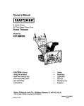
1
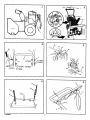
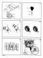
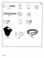
InstructionBook
Manueld'instructions
SnowThrower
Model 624604x35
chasse-neige
mod#.le 624604x35
Read and keep this book for future reference. This book contains important Information on SAFETY,
ASSEMBLY, OPERATION, AND MAINTENANCE.
Lisezet conservezce manuelpourr6f6rence.Cemanuelcontientdesinformationsimportantes
concernantla SECURITE,LEMONTAGE,L'UTILISATION
ETL'ENTRETIEN.
F-OO1052J
11I01/99
NOTE: This unit is equipped with an iatema! combustion engine
and must not be used on or near any unimproved
forest-covered, brash-covered or grass-covered land unless
the engine's exhaust system is equipped with a spark arrester
meeting applicable local or state laws (if any). If a spark arrestor
is used, it must be maintained in effective working order by the
operator.
In the State of California, the above is required by law (Section
4442 of the Califomia Public Resources Code). Other states
may have similar laws. Federal laws apply on federal lands. See
an Authodzed Service Center for a spark arrestor for the
muffler.
REMARQUE : carte machine est 6quipde d'un moteur
combustion interne et ne doJtpas 6tre utilisde sur un terrain
forestier, buissonnant ou herbeux non pr6par6, _ moins que Io
dispositif d'6chappement soit pourvu d'un pare--.6tincelles
conforme _. la 16gislation locale ou de 1'6tat(le cas 6ch6ant). Si
un pare--6tincelles est utilisd, celui-ci dolt 6ire maintenu en
parfait 6tat do fonctionnement par rutilissteur.
Le syst_me
Au seln de 1'6tatde Califomie, la Ioi exige la pdss en compte
des pr6cautions montionndes ci-dessus (clause 4442 du
California Public Resources Code). D'autres 6tats peuvent
prdsenter des lois similaires. Los lois f6derales s'appliquent sur
les terres f6d6rales. S'adresser t_ un centre de maintenance
agr66 pour I'achat d'un pare_tincelles
F-0010_
d'dchappement
de cette
unit6
contient
des
sub.stances
chimiques,
qui
selon
I'Etat
de
Californie, peut causer le cancer, des
malformations ta la naissance, ou un
danger pour la reproduction.
pour I'fJchappement.
2
_/
1
3
+t
_'_9
4 (67_} 4
5 (71071)
_7(71037)
_4
10
2_
,/1
3
I
7 (71037),,,
+ 5 (71071)
f/4
(6751)
!1
_7
6 (71060) /
6 (71060)
0
4
6
5
/
51
F-OO1052J
3
Z
4
8
5
4
Io
2
f
2
8
//
3
7
/2
3
1
2
F-OO1052J
4
5
/3
14
2
6_
7
!0
16
13
12
3
10
15 ¸
17
/8
1
6
2
\
5
F-O01052J
.5
/9
2O
5
\
/'.62cm '
2/
,
22
//
23
4
F-OO1052J
6
2- 6751
©
©
2- 71060
2- 71071
24
2- 71037
G©
2- 9524
2- 3943
2-
©
3- 586280
1- 304438
F--OO1052J
3- 71071
1- 318486
73826
D@
3- 71038
1- 6219
7
Murray,Inc.warrantsto the originalpumhaser
that thls unit shallbe _ea from defectsin
matedaiandworkmanshipundernormaluse
andservicefor a pedod of Two (2) Year from
the date of purchase;however,thiswarran_
does notcoverengines,accassodes(suchas
electricstarters)and NormalWear Parts (except
as notedbelow)as the companiesthat
manufacturethese itemsfumishtheirown
warrantiesandprovideservicethroughtheir
atdhodzedfieldservicefacilities.For additional
Information, see thewarrantiescovedngthese
parUcularparts.If youare uncertainwhether
ycur unitcomains or is eduipped with one or
moreof these parts,coosuit yourdealer pdorto
pumhase.Subjectto the termsand conditions
noted in this limited Warranty, we shait, at cur
option,repairor replaceat no costto the original
purchaserany partcoveredby thisUmited
Warrantydudngthe applicablewarrantypedod.
NormalWear Parts are definedas ddvs belts,
augers,shear pins,tires and headlights.These
partsare warrantedto be free from defectsin
matedai andworkmanshipas deliveredwith the
product.Any claimfor repairor replacementof
NormalWear Parts must be made withinthirty
(30) days ofthe date of purchase.No claims
involvingdamagecaused from rnatedaluse,
abuse or misusewill be honored.
This Murray,Inc. Two (2) Year Limited
Warranty is yourexclusiveremedy; however,
this warrantyis voidor does notapplyto any
unitthat has been tampered with,altered,
misused,abusedor usedfor rentalor other
commercial and/orprofessional
(non-homeowner)uses.Yourwarrantydoesnot
coverminor mechanical adjustmentswhichare
not dueto any defect in material or
workmanship.For assistancein making such
adjustments,consultyourInstructionBook.
To make a claimunderthis Murray,Inc. TWO(2)
PRODUCT
reference.
CONTENTS
PRODUCT INFORMATION
OWNER'S INFORMATION
INTERNATIONAL PICTORIALS
ASSEMBLY
OPERATION
MAINTENANCE
MAINTENANCE CHART
TROUBLE SHOOTING CHART
TWO YEAR
LIMITED
8
B
9
11
11
14
14
17
WARRANTY
INFORMATION
The owner must be certain that all the product
information is Included with the unit. This
Intormstfon Includesthe INSTRUCTION
BOOKS, the REPLACEMENT PARTS and the
WARRANTIES. This informaiton must be
inoleded to make sure state taws and other _ws
are followed.
OWNER'S INFORMATION
This instruction book is wdttan for a person with
some mechanical ability. Like most service
books, not all the steps are described. Steps on
how to loosen or tighten fasteners are steps
anyone can follow with some mechanical ability,
Read end follow these instructions before you
use the unit.
Know your product: If you understand the unit
and how the unit operates, you will get the best
performance. As you read this manual, compare
the illustrations to the unit. Learn the location
and the function of the controls. To help prevent
an accident, follow the operating instructions
and the safety rules. Keep this manual for future
F-001052J
IMPORTANT: Many unitsare notassembled
and are soldin cartons, it Is the responsibility
of
the ownerto make sure the assemblyinstructions in this manual are exactlyfollowed. Other
unitsare pumhasedin an assembledcondition.
On assembledunits,it isthe responsibility
of the
ownerto make sure the unit iscorrectly assembled.The ownermust carefullycheckthe
unitaccordingto the instructionsin thismanual
beforeitIstirst
used.
Year Umited Warranty, returnthe unit(or if
authorizedIn advance, the defectivepart) along
with yourproofof pumhaseto an Authorized
CenterP_r you.To foceta the neerast
AuthorizedServiceCenter, callthe CentralPads
Distributorfor yOUrarea shownin the list
providedwith yourunitor check the YellowPage
listingsIn yourlocaltelephonedirectory.If you
returnthe entire unit,we will repairthe unit. If we
au_odxa the returnof the detectivepart only,we
willeither replaceor repairthe part.ThisMurray,
Inc.Two (2) Year Limited Warranty givesyou
specificlegalrights,and youmay also have
other dghtswhichvary from stateto state, This
Limited Warranty Is given in lieu of ell other
expressed end Implied warranties Including
the Implied warranty of merchantability and
warranty of fitness for a pertlcutar purpose. If
you needadditionalinformation on this wdttan
warrantyor assistancein obtainingservice,
write:
MURRAY CANADA, INC.,
Factory Customer Service
1195 Cou_eyperk Drive East
Miseisasuga, Ont. L5T-1R1
1-800-661-6662,
2.
Followall the assemblyand preparation
instmcSoos.
3.
4.
Inspect the unit.
Make sure that the operatorof the unit
knowshow to correctly use all standard
and accessoryequipment.
Operatethe unitonlywithguards,shields,
and other safety items in placeand woddng
correctly,
Correctlyadjustthe unit.
Servicethe unitonlywith authorizedor approvedreplacementpads.
Completeall maintenanceon the unit.
5.
6.
7.
8.
Environmental
WARNING: Look fer this symbol to indicate
important e|detyprecautions, This symbol
Indicates: "Attention!
Become AlertI Your
Safety Is At Risk."
Responsibility Of The Owner
The responsibility of the owner Is to
follow the Instructions below.
1.
Carefully read and follow the rules for safe
operation.
8
Awareness
•
Do notfill the engine'sfueltank completely
full.
•
•
•
•
Drainfuel for off-seasonstorage_
Use onlyunleaded gasoline.
Service the air cleanerreguledy.
Change oilregutarly.Use 5W-30 oil.
•
•
Tune-up the engineregularly.
Keep equipmentin efficientoperating
condition.
•
Disposeof usedengine oilproperly,
INTERNATIONAL
PICTORIALS
IMPORTANT:The following pictorials are Io¢cted on your unH or on Iltorcture supplied
with the product. Before you operate the
unit, learn and understand the purpose for
each pictorial.
Safety Warning Symbols
25
DANGER
Thrown Objects.
Keep Bystanders Away.
DANGER
Thrown Objects.
Keep Bystanders Away.
DANGER
Avoid Injury From
Rotating Auger. Keep
Hands, Feet And
Clothing Away.
IMPORTANT
Read Owner's Manual
Before Operating
This Machine.
WARNING
m
WARNING
Hot Surface
STOP
Control And Operat_ols
Slow
0
DANGER
Stop The Engine
Before Unclogging
Discharge Chute[
(_
Fast
Electric Start
I
I,I
Engine Stop
On
Choke Off
Reverse
Throttle
Primer Button
Push To Engage
Electric Starter
Engage
Discharge
LEFT
Weight Transfer
Lift Handle To Engage
F-001052J
Discharge
RIGHT
_
_)
Engine Start
I-I
Choke On
_
Engine Run
Engine Off
N
Neutral
Forward
Ignition Key
Ignition Off
ignition On
Auger Clutch
Auger Collector
Discharge DOWN
Discharge UP
Drive Clutch
Fuel
0
Weight Transfer
Depress Pedal To Disengage
Transmission
9
Oil
Fuel Oil Mixture
Ignition Key
Insert To Run, Pull Out To Stop.
Safe Operation Practices for Snow Throwers
As Recommended By: American National Standards Institute.
IMPORTANt': Safety standards require operator
presence controls to mir_ze
_ dsk of injury.
Your snow thrower is equipped with such contrcls. Do not attempt to defeat the function of the
operator presence control under any circumstances.
Training
1.
Read the opem_ng and service instruction
manual cerafdily. Be thoroughly familiar with
the controls end the proper use of the equipment. Know how to stop the unit and disengage the controls quickly.
2.
Never allow children to operate the equipment. Never allow adults to operate the
equipment without proper instruction.
3.
Keep the area of operation clear of all persons, particularly small children and pets.
4.
Exercise eau_on to avoid slipping or falling
especially when operating in reveme,
7,
Neverattempt to makeany adjustments
_
tha e_ne (motor)is rur_._ (except
when specificallyrecommendedby manufacturer).
11. DO not clear snow across the face of slopes.
Exerdsa extreme cau_on when chang
direction on slopes. Do not attempt to clear
steep slopes.
B.
Leeengine(n_toz) andsnowthrower adjust
to outdnortemparatursabeforestartingto
clear snow.
12. Never operate the snow thrower without
proper guards, plates or other safety protective devices in place.
9. Alwayswearsafetyglassesor eye shields
duringoperationor while performingan edjuslmontor repair to protecteyesfromforeign
objectsthat may be "_nrown
fromthe snew
thrower.
14. DO not ovodoad the machine capacity by attempting to deer snow e.t too taee a rata.
Opemtlon
I.
2.
Disengageall clutchesbefore startingthe engine(motor),
3.
Do not operatethe equipmard withoutwearingadequatewinter outer garments, Wear
footwearthat will improvefoo_ng on slippery
surfaces.
4.
Handle fuel with care; it is highly flammable.
a.
Usa an approvedfuelcontainer.
b. Never removefuel tank cap or edd fuel to
a runningengine (motor) or hot engine
(motor).
c. Fillfuel tankoutdoorswith extremecare.
Never fillfuel tank indoors.
d.
Replace fuee cap securely end wipe u_
spilled fuel.
e.
Never store fuel or snow thrower with fuel
in the tank inside ot a building where
fumes may reach an open flame or spark.
f,
5.
Check fuel supply before each use, allowing space for expansion as the heat of the
engine (motor) and/or sun can cause fuel
to expand.
For all units with electric starUng motors use
electric starting extension cords certified
CSA/UL. Use only with a receptacle that has
been installed in accordance with local inspection authorities.
6.
Adjust the snow thrower height to clear gravel
or crushed rock surface.
F-001052J
Do notoperatethis machineif youare taking
drugeor o_r med'_..st_n
wi't_h can cauae
drowsinessor affect yourabilityto operate
this machine.
15. Never operate the machine at high transport
speeds on slippery surfaces. Look behind
end use care when bacl,_m_Jup.
16. Never direct discharge at bystanders or allow
anyone In front of the unit.
2.
Do nct uae this machine if yeg are mentaity
or physicallyunableto operatethis machine
safely.
17. E/ksengage power to the conector/=mpetier
when snow thrower is transported or not in
use.
3.
Do notputbends or feetnear or underrotatingparts. Keepclearof the dischargeopeningat all times.
18. Use onlyattachments and accessadesapprovedbythe manufacturerofthe snow
thrower (suchas tire chains,elestdcstartkits,
Preparation
1. Thoroughlyinspectthe area where the equipment is to be usedand removeall doormats,
sleds,boards,wires,endothorforeignobits.
13. Never ope_ta tbe snow thrower near enclosures, automobiles, window wells, drop-olts,
the like without proper adjuslment of the
snow discharge angle. Keep children and
pets away.
4. Exerciseextremeca_on whenoperatingon
or crossinggravelddves,walksor roads.
Stay alertfor hiddenhazardsor traffic.
5. Aiters_ldng a foreign object,stopthe engine
(motor),removethe wirefromthe sparkplug,
thoroughlyinspectsnowthrower for any
damage,and repairfile
damage beforerestarlingandoperatingthe snowthrower.
6.
If the unitshouldstartto vibrateabnom'Blly.
stopthe engine(motor)andcheckimmediatelyfor the cause.VibrationIs generallya
warningoftrouble.
7. Stopthe engine(motor)whenever youleave
the operatingpoaltion,before uncloggingthe
augar/impallarhousingor dischargechute
andwhenmakingany repairs,edjuslments,
or inspections.
8. Wbe_ desKmg,repairing,or lus_g,
make
certainthe augariimpallorandall moving
partshavestoppedandall controlsare disengaged.Disconneofthe sparkplugwire and
keep the wire away fromthe sparkplugto
preventaccidentalstarting.
9. Takeall passible precautionswhen leaving
the snowthrower unattended.Disengagethe
auger/impeller,stopengine(motor),and removekey.
10. Donot runthe engine(motor)indoors,except
whensta_ng the engine(motor)andfor
transporting
the snowthrower in or outof the
building.Open the outsidedoors;exhaust
fumes are dangerous(containingCARBON
MONOXIDE, an ODORLESS andDEADLY
GAS).
10
19. Neveroperatethe snowthrower without good
visibility or lighLAlwaysbe sureof yourfontingend kespa tirm hok:len the hand_es.
Walk;neverrun.
20. DOnotover-reach. Keep properfooting and
balance eeaUtimes.
21. Exercisecau_on ifoperatingon steepsloping surfaces.
22. This snowthroweris for use on sidewalks,
drivewaysandother groundlevel surfaces.
23. DOnot usethe snowthrower on surfaces
above groundlevel suchas roofsof residences,garages, porchesor other such
structuresor buildings.
Maintenance And Storage
1. Check shearboltsand otherboltsat frequent
intanralsfor propertighthsssto be sure the
equipmentis in safewoddngconcli_on.
2. Neverstorethe snowthrowerwithfuel inthe
tankinsidea buildingwhere JgnJtiorl sources
are presentsuchas hotwater andspace
heaters,clofbesdryers,andthe like.Allow
the engine(motor)to coolbefore stodng in
any enclosure.
3. Alwaysreferto operator'sguideinstructions
for importantdetailsif the snowthrower isto
be storedfor an extendedpedod.
4. Maintainor replacesafetyandinstructionlabeis,as necessary.
5. Runthe snowthrower a fewminutes after
throwing snowto preventfreeze-up ofthe
auger/impeller.
ASSEMBLY
Read and followthe assemblyand adjustment
i_s
foryoursnowthrower.Allfasteners
are in the partsbag. Do not discardany parts or
materialuntilthe unitis assembled.
5. (Flgure4)Cutthecabletiethatholds_e
upper crank rod (10) to the handle. Carefully remove the cotter pin (12) and clevis pin
(13) from the yoke (17) on lower end of the
upper crank rod (10). Do not remove the
universal joint pin (14).
NOTE: Make sure the universal Joint pin
(14) and the universal joint (16) ere
mounted in the yoke (17). If not, secure
the universal joint (16) inside the yoke
(17) with the universal Joint pin (14).
assembly or maintenance to the
A
WARNING: Before doing any
snow thrower, remove the wire
from the spark plug.
NOTE: In this instruction book, left and right
describe the location of s pert from the operator's position behind the unit.
NOTE: Torque is measured in foot pounds
(metric N.m). This measurement describes
how tight a nut or bolt must be. The torque is
measured with a torque wrench.
NOTE: Illustrations
begin on page 3.
NOTE: To assemble the following loose
parts, use the fasteners shown at full size in
Figure 24.
1
Pliers
1
1/2 inchadjustableopen endwrenches
1
9/16 inchadjustableopen end wrenches
1
3/4 inchadjustableopen endwrenches
1
1
Measuringtape or ruler
Screwdriver
How To Remove The Snow Thrower
From The Carton
1. (Figure/)The snowthrower b shownin the
shippingposition.
2. Locateall partsthat are packedseparately
andremovefrom the cadon.
3. Remove and discardthe packingmaterial
fromaroundthe snowthrower.
4. Cutdown all fourcomersof the cartonand
lay the side panelsfiat.
5. Holdontothe lowerhandle andpullthe snow
thrower offthe carton.
CAUTION: DO NOT back over cables.
6. Remove the packingmaterial fromthe handle assembly.
7. Cutthe tiesthat secure _e clutch control
cables (1) to the lower handle (2). Move the
cablesaway from the motor frame.
Crank
TO Assemble
8. (Figure 3)'tighten nut (9) on eye bolt (11).
Make sure eye bolt (11) is properly aligned
and the crank (18) can freely rotate.
9. "lighten all handle fasteners,
Check
Tools Required
1
Knife
How
6. Hole the universal Joint (16) in place and
slide the upper crank rod (10) down through
the eye bolt (11) and onto the yoke end of
the lower crank rod (15).
7. Secure the upper crank rod (10) to the lower crank rod (15) with clevis pin (13) end
cotter pin (12). Spread the ends of the cotter pin (12) to lock in place.
The Handle
And
Assembly
1. (Figure 3) Loosen, but do not remove, the
fasteners (1) in the upper holes of the lower
handle.
2.
(Figure 2) Put the shift lever (6) into first
forward position.
3.
(Figure 3) Raise the upper handle (2) to the
operating position.
NOTE: Make sure the cables are not
caught between the upper and lower handle.
4. Install the screw (4), flatwasher (5), lockwasher (6), end hex nut (7) into the bottom
holes on each side of the handles. Make
sure fasteners in the bottom holes are tight.
F-001052J
skids, see "How To Adjust The Height Of The
Skids" in the Maintenance section.
How To Prepare The Engine
Note: The engine was shipped from the factory filled with oil Check the level of the oil.
Add oil as needed. Engine does not contain
GASOLINE.
manufacturer's
Jnstruutlons for the
ARNING: Follow the engine
type of fuel and oil to use. Always
use a safety fuel container. Do not smoke
when adding gasoline to the engine. When
inside an enclosure, do not fill with gasoline. Before you add fuel, stop the engine.
Let the engine cool for several minutes.
A
Check the oil, See the engine manufacturer's
instructions for the type of fuel and oil to use.
Before you use the unit, read the information on
safety, operation, maintenance, and storage.
OPERATION
NOTE: Itiustrations
The Cables
begin on page 3.
1. (FlgureS)Chec_thetracflondriveeeble
(1) and the auger drive cable (2). If the bottom of the cables have become disconnected, reinstall the cable springs. Make sure
the long spring (3) is attached to the traction
drive and the short spring (4) is attached to
the auger drive.
Know Your Snow Thrower (Figure 2)
Read this InstructionBookand safety rulesbefore operationthe snowthrower. Comparethe
Ulustrafionwith yoursnowthrower to familiarize
yourselfwith the locationof variouscontrolsand
adjustments.
2.
(Figure 6) If the top of the cables (5) have
become disconnected from the drive levers
(6), attach the cables (5) to the "Z" fitting
Traction Drive Lever (1) - Select the forward or
reverse direction of travel.
(7).
Crank Assembly (2) - Changes the direction of
the discharge chute.
How To Assemble The Snow Chute
(Figure 7)
1. installthe snow chute (1) ontothe snow
chute flange (2). Alignthe three holes in the
snow chute (1) withthe holesin the snow
chute flange (2).
2. Fastenthe snow chute (1) to the snow
chute flange (2) with carriage bolts (3),
washers (4) end nuts (5). Make surethe
carriage bolts (3) are installedwiththe head
of the bolts (3) on the insideof the snow
chute flange (2) as shownin the illustration.
3. Make sure all fastenersare tight.
NOTE: DO NOT overtighten the fasteners.
How To Install
(Figure 8)
The Shift
The traction drive cable and the auger drive
cable are adjusted at the factory. Before operating, make sure adjustment of the cabins have
not changed. See =How To Check And Adjust
The Cables" in the Maintenance section.
Height
Auger Drive Lever (5)- Startsandstopsthe auger andimpeller(snowgatheringand throwing).
Speed Shift Lever (6) - Selects the speed of the
snow thrower.
Height Adjust Skid (7) - Ad usts the ground
clearance of the auger hous ng,
Ignition Key (8) - Must be inserted to start the eng=ne.
Primer Button (9) - Injects fuel directty into the
carburetor for fast starts in cold weather.
Switch Box (11) - On electric start models
to attach a 120 volt e ectric power cord,
used
Recoil Starter Handle (12) - Use to manually
start the engine.
Throttle Control (13)engine.
Controls the speed of the
Choke Control (14) - Use to start a cold engine.
The Cables
How To Set The Skid
Changes the distance the
Electric Start Button (10) -On electric start models, used to start the engine,
Knob
1. Install the hex jam nut (3) onto the end of
the speed shift rod (2).
2. thstall the knob (1) outo the speed shift rod
(2) until the knob (1) is snug against the he](
jam nut (3). To look in position, tighten the
hex jam nut (3) against the knob (1).
How To Check
Discharge Chute (3)snow is thrown.
(Figure
How To Control
The Discharge Of The Snow
A
charge
of snow
WARNING:
Nevertoward
direct bystanders.
the dis-
2)
The snow thrower is equipped with height adjustable skids (7) mounted on the outside of the
auger housing (4), To adjust the height of the
11
before
unclogging
ARNING:
Always the
stopdischarge
the engine
chute or the auger housing and before leaving the snow thrower.
A
ENGL/SH
1. (Figure 2) Turn the crank m$_mmbly(2) to
change the discharge dlrec_onof the snow.
2. (Figure 9) Loosen the wing knob (1) on the
chute deflector (2).
3. Movethe chute deflector (2) up for more
distanceor downfor leas distanc•.
4. "nghtanthe wing knob (1).
How To Stop
The Snow Thrower
3. OLsnoor,.eot
the kRokPin (1) fromthe wheel
locked position (2). Pushthe kllck pin (1)
through the unlockedaxle holeonly. The unit
is now in the singlewheeldrive unlocked
position (3).
Before
Starting
The Engine
1. Before you service or stad the engine, familiarize yourself with the •now thrower. Be
sure yon understand the function and location of all controls.
(Figure 2)
1. To stop discharging snow, release the auger
drive lever (5).
2. To stop the wheels, release the traction
drive lever (1).
2, Check the tension of the clutch cable before
3. To stop the engine, push the throttle control
lever (13) to off and remove the Ignition key
(S).
3. Make sum that all fasteners
How TO Go Forward or Backward
(Figure 2)
1. Tochange the grcundspeed, first release the
traction drive lever (1) andthen move th•
speed shift taver (6) to the desired speed,
2. Groundspeed is determinedby•now conditions.Select the speed bymovingthe •poed
• hift lever (6) intothe appropriatenotchon
the shift leverplate.
Speed 1, 2
Wet, Heavy
Speed 3
Light
Speed 4
VeryLight
Speed 5, 6
Transportonly
3. Togo forward,engagethe traction drive
lever (1). Maintaina firm holdon the handle
as the snowthrower startsto move forward.
Guidethe snowthrower by movingthe bandie either left or dght. Do not attempt to push
the snowthrower.
4. To go backward,releasethe tractor drive
lever (1).
5. Movethe speed shift lever (6) intoeith•r
firstor second reverse.
6. Engagethe traction drive lever (1).
IMPORTANT: DO not move the speed shift
lever (6) while the traction drive laver (1) i•
engaged.
How To Throw Snow (Figure 2)
1. Engageth• auger drive lever (5).
2. To stopthrowingsnow,release the auger
drive lever (5).
snow thrower can result In foreign
ARNING: The operation of any
objects being thrown Into the eyes,
which can result in severe eye damage.
Always wear safety glease• or eye shields
while operating the snow thrower. We recommend standard safety glasses or use e
wide vision safety mask over your glasses.
A
How To Use The Wheel
Lockout
Pin
(Figure 10)
1. _
left hand wheel is secured to th• axle
with a klick pin (1). This unit was shipped
wi_ this kllek pin (1) through the wheel hole
In the tacked position (2).
2.
For ease of maneuverability in light snow
conditions, change th• klick pin (1) to an
unlocked position (3).
F-001052J
starting the engine. See "How To Adjust Th•
Clutch Cable" in the Maintenance section of
this manual.
ere tight.
4. Make sure the height adjust skids are properly adjusted. See "How To Adjust The Height
Of The Skids" in the Maintenance section of
this manual.
5. Check the air pressure in the tires, The correct air pressure is 14 PSI (1 BAR) to 17 PSI
(1,25 BAR), Do not exceed the maximum
amount of air pressure shown on the side of
_e tire.
How To Stop The Engine (Figure2)
To stopthe engine,move the throttle control
(3) to the stop positionand removethe Ignition
key (8). Keepth• Ignlttan key (8) in a safe
place. The enginewill notstartwithoutthe Ignition key (8).
How To Start The Engine (Figure2)
Models equipped with an Electric Starter
NOTE: An electric starter Idt can be added to
recoil •tart engines. Electric starter kits am
available from your nearest authorized service center,
3. Make sum the trectton drive laver (1) and
the auger drive lever (5) are in the disengaged (released) position.
4. Move th• throttle €ontrol (13) to the fast
position.
5. Ins•rt the Ignition key (8) into the ignition
slot. Make sum the IgnIflon key (8) •naps
into piece. Do not turn the ignition key (8).
Remove th• •xtra ignition key and keep in a
sets place.
6, Move the choke control (14) to the full
choke position.
7. (ElectricStart)Connectthepow•rcordto
the switch box (11) located on the engine,
8. (Electrio Start) Plug the other end of the
power cord into a three-hole, grounded 120
VOLT, A.C. receptacle. (See the WARNING
in this section).
9. Push the primer button (9). Every time you
push the primer button (9), wait two seconds. For the number of times required to
push the primer button (9), see the engine
manufacturer's instructions.
10. (Electric Start) Push on the electric start
button (10) until the engine starts. Do not
crank for more than 10 seconds at a time.
The electric starter is thermally protected. If
the electdc starter overheats, it wil! automatically stop and can only be restarted when it
has cooled to a safe temperature. A wait of
about 5 to 10 minutes is required to allow the
electric starter to cool.
11. (Recoil Start) Rapidly pull the recoil starter
handle (12). Do not allow the recoil starter
handle (12) to snap back. Slowly return the
recoil starter handle (12).
12.1f the engine does not •tart in 5 or 6 tdes,
See the "Trouble Shooting Cha_ Instructions.
13. (Electric Start) Wh•n the engine starts, release the electric start button (10) and
move the choke control (14) to 1/2 choke
positlan. When the engine runs •monthly,
move the choke control (14) to the off position.
A
with
a three-wire
poweriscord
and
ARNING:
The starter
equipped
plug and Is designed to operate on
120 volt A,C. household ourront. The power
cord must be properly grounded at ell times
to avoid the poaslbllfty of electrical •hock
which can Injure the operator. Carefully follow all instructions in the "How To Start The
14. (Electric Start) First disconnect the power
cord from the three-hole receptacle. Then,
disconnect the power cord from the swltah
box (11).
NOTE: In temperatures below O°F, allow
the engine to warm up for several minutes
before blowing •now,
Engine" section. Make sure that your house
wiring is • three-wire grounded system, if
you ere not sure, ask a licensed electrician.
If your house wire system Is not a
three-wire grounded system, do not use
this electric starter under any conditions. If
your system is grounded but a three-hole
grounded receptacle is not •vail•ble to start
the engine, have a three-hole grounded reooptacle installed by a licensed electrician.
To connect a 120 volt A.C. power cord, always connect the power cord to the •witch
box (11) on the engine first. Then, plug the
other end into the three-hole grounded rensptecle. When disconnecting the power
cord, always unplug the end from the
three-hole grounded receptacle first.
15.Whec throwing snow, always run the engine
with the throttle control (13) in the fast position.
How To Start A Cold Engine (Figure 2)
1. Check the engine oil.
2. Fill the fueltankwith regular unleadedpetrol.
See "HowTo PrepareThe Engine'.
12
indoors or th
enclosed,
venWARNING:
Never
run thepoorly
engine
tilated areas. Engine exhaust contales carbon monoxide, an odorless and
deadly gas. Keep bands, feet, hair end
loose clothtag away from any moving parts
located on the engine or the snow thrower.
The temperature of muffler end nearby
area• mey exceed 150°F. Avoid these
areas.
,_lk
How To Start A Warm Engine (Figure 2)
If an engine has been running and is still warm,
leave the choke control (14) in the off position
and do not push the primer button (9). If the
engine tail• to start, folk_w _ inst_s
"How
To Star A Cold Engine".
NOTE: Do not use the primer button (9) to
start • warm engine.
ENGL/SH
How TOStart An Engine W'_h A Frozen Electric
Starter (Figure 2)
How To Remove Snow or Oebds From
The Auger Housing (Figure2)
2. Mostefficientsnowthrowing is accomplished
when the snowis removedimmediatelyafter
if falls.
move
snow Do
or debris
that may
beARNING:
not attempt
to re©ome lodged In auger housing
without taking the following preeautlen$.
3. For completesnow removal,slightlyovedap
eachpreviouspath,
4. Wheneverpossible,dischargethe snow
downwind.
If the electdc starter is frozen and wilt not fum
the engine, follow the instructions below.
1. Pug out the recoil starter handle (12) as far
as possible.
2. Quickly release the recoil starter handle
(12). Ntow the r_oll
starter handle (12) to
snap beck against the recoil starter.
If the engine still fails to start, repnet the two previous steps until the engine starts. Then, continue with the directions =How To Start A Cold
Engine".
To help prevent the possible frseze--up of the
recoil starter and of the engine contruis, proceed
as foitows s_tm each snow removal JGo.
1. With the engine running, quickly pull the recoil Starter handle (I 2) three or four times
with e continuous full arm stroke. This will
produce a loud clettadng sound that is not
harmful to the engine or starter.
2. Stop the engine. Wipe all snow end moisture
from the carburetor cover, control levers and
cables. ALsomove the throttle Gontrol (13),
©hoke control (14), and recoil starter handle (12) several times.
F--001052J
A
1. Releasethe auger drive lever (6).
2. Movethe throttle control (13) tothe stop
position.
3. Remove (do net turn)the Ignltloo key (8).
4. Disconnec_the sparkplug wire.
5. Do not placeyourhandsin the auger housIng (4) or the discharge chute (3). Use a
pry barto removeany snowor debds.
Snow Throwing Tips
1. For maximumsnowthrower efficiency,
changethe groundspeed,NEVER change
the engine speed, The engine is designedto
delivermaximumperformanceat full throttle
and most be runin the fastpositionat all
times. In deep, freezing,or wet snow,reduce
forwardspeed. If the wheelsslip,also reduce
forwardspeed,
13
5. For nermat usage,set the skidsso that the
scraperbar is 1/8"above the skids. For extremelyhard-packod snowsurfanes,adjust
the skidsupwardso that the screporbet
touchesthe ground.
6. Rocksand gravelmustnot be pickedup and
thrownbythe machine.On gravelor crushed
rocksurfaces,set the skidsat I-I/4 inchbelowthe scraperbar. See "HowTo AdjustThe
HeightOf The Skids"in the Maintenance
section.
7. Afteree,chsnowthrowing_b, allow the engineto idlefor a few minutes.The snowand
accumulatedice will meltoftthe engine.
8. Clean the snowthrower after eachuse,
9. Remove ice,snowand debdsfrom the entire
anow thrower. Rush with water to removeall
saltor otherchemicals.Wipe snowthrower
dry.
MAINTENANCE
CHART
CUSTOMER RESPONSIBILITIES
SERVICE RECORDS
Fill
In datesregular
as you
complete
service.
Before
Each
Use
Rrst
2
Hours
Every
.
Hours
Every
..
Hours
very
Ezo
Hours
Change Engine Oil
_/
Check Spark Plug
_/
Check Fuel
Each
Season
_
N/
_/
Lubdcete Auger Shaft
(See Shear Bolt Replacement)
"J
MAINTENANCE
NOTE: Illustrations begin on page 3.
Use the followingmaintenancesectionto keep
you_unit_ngoodoperating conditk>n.._lthe
m_ntanance informationfor the engine is in the
enginemanufacturer'sinstructions.Beforeyou
startthe engine, read this book.
spantion, adjustment (except
ARNING: Before you make an Incarburettor), or repair, disconnect
the wire from the spark plug.
A
General Recommendations
The warrantyon this snowthrowerdoes not cover itemsthat have been subjectedto operator
abuseor negligence.To rscalvofullvalue from
the warranty,the operatormust maintainthe
snowthrower as instructedin this manual.
Some adjustmentsmust be made periodicallyto
pmpsdymaintainthe snowthrower.
NI adiustmants la the Maintenance
ce_ion of
this manual should be checked at least once
each season,
As Required
The following adjustment should be preformed
more than once each season.
1. Adjust the auger ddve belt after the first 2 to
4 bourn, again at mid-eaason, and twice
each season thereafter. See "How To Adjust
The Auger Ddve Belt" in the Maintenance
section.
Lubrication
Every 10 Hours (Figure 11)
1. Lubdcatethe Zork ffttlngs (1) every tan
hourswith a grease gun.
2. Each timea shear boltis replaced,the auger
shaft mustalso be greased.
3. Lubricateall pivotpoints.
Use
•
Check for any loose or dan',aged parts.
•
Tighten any loose fasteners.
•
Check and rnaJntsinthe auger.
•
Check controls to make sure they are
functioning pmpedy.
•
DATES
._
Lubdcate Disc Ddve Plate Zsrk
(See Maintenance)
Each
SERVICE
N/
Check Auger Clutch Cable Adjustment
(See Cable Adjustment)
After
Before
Storage
If any parts are wom or damaged,
immediately.
F-001052J
replace
Every 25 Hours (Figure 12)
Lubdcatsthe disc drive plats (1) every 25
hours,at the end ofthe season and beforestorage.
1. (Figure 2) Movethe speed shift lever (6) to
firstgear.
2. Remove the gas from the gas tank. Stand
the snowthrower up on the frontendof the
auger housing (4).
14
"_
A
doors, away from fire or flame.
ARNING: Brain the gasoline out-
3. (Figure 18) Remove the bolts (1) on each
side of the bottom panel (2).
4. Loosen the bolts (3) on each side of the bettom panel (2).
5. Remove the bottom panel (2).
6. (Figure 12)Tum the disc drive plate (1)
clockwise by hand until the Zerk fitting (2) is
visible.
7. To prevent the rubber friction wheel (3) from
contacting the drlve disc plate (1), put a
coin (4) (or a shim of equal thickness) betwean the rubber friction wheel (3) and the
disc drive plate (1).
8. Lubricate the Zerk fitting (2) with a grease
gun. Use a high temperature EP Moty
grease. Fill the Zerk fitting (2) only until
grease becomes visible below the bearing
assembly (5) located under the Zerk fitting
(2). DO NOT over fill. Clean all excess
grease from the friction disc hub.
CAUTION: Do not allow grease to coma
In contract with the disc drive plate (1) or
the friction wheel (3) or damage will resuit.
9. Remove coin (4) used in step 7. Make sure
that a gap exists between the friction wheel
(3) and the disc drive plate (1).
tO.(Figure 18) Install the bottom Imnel (2).
11. Tighten the bolts (3) on each side of the bottom panel (2).
12.Install the bolts (1) on each side of the bottom panel (2).
ENGL/SH
ItemsNotToLubricate(Figure
12)
1. Do not lubricate the hex shaft end sprockets (6). All bearings and bushings era lifetime lubricated. For storage, put e slight
amount of 5W-30 motor o11on a cloth and
wipe the hex shaft and sprockets (6) to
prevent rust.
2. If greece or oil comes in contact with the
disc drive plate (1) or the friction wheal
(3). the friction wheal (3) can be damaged.
Make sure to thoroughly clean the disc drive
plats (1) and the friction wheal (3).
CAUTION: Any greasing or oiling of the
above components can cause contemthaflon of the friction wheel (3), If the disc
ddve plate (1) or the friction wheel (3) become contaminated with grease or o11,
damage to the friction wheel will result.
3.
The auger gear case is lubricated at the factory and does not require add'Krona!lubrication. If for some mason the lubricant leaks
out, have the auger gear case checked by a
le_;tory authorized service cectar.
4. Adjust the sorsw bar (15) to allow 1/8 Inch
clearance between the scraper bar (15) and
the sidewalkor area to be cleared.
5. Tightan the carriage boltsand nuts.Make
surethat the scraper bar (15) is parallelwith
the sidewalkor area to be cleared.
6. To sxtaeded the |'riaof the sor_0er bar (15),
removeand reversethe mountingof the
scraper bar (15).
The tractiondrivecable andthe augerdrive
cable are adjustedat the factory.Duringnormal
use, a cable can becomestretchedand mustbe
checkedand adjustedas follows,
3. (Figure 16) Loosenthe nut (2) an the Idler
pulley (3) Movethe Idler pulley (3) 1/8 inch
towardthe auger drive belt (4).
4. Tightenthe nut (25.
5. (Figure 17) Depressthe auger drivelever.
Check the tensionon the auger drive belt
(45. In correct e_usbnent,the a,,._gerdrive
belt (4) willdeflect 1/2 Inch (5) with moderate pressure.If the adjustmentis notcorrect,
repeat the adjustment.
6. (Figure 15)lnstallthebeltcover(1). _ghten
SCreW(2).
7. Check the adjustmentof the augerddve
cable. See =HowTo Check AndAdjustThe
Cables"in the Maintenancesection.
8. Attachthe sparkplugwire.
How To Check The Cables (Figure 13)
Traction Drive Belt
1. To check forcorrect adjustment,disconnect
the "Z" fitting (1) fromthe drive lever (2).
2. Move the drive lever (2) forwarduntilthe
drive lever stop (9) is conta_ng the handle
The tractiond_a be_thas constantspi_'_ pressureand does not require an adjustment.If the
tractiondrive beltis slipping,replacethe belt.
See =HowTo ReplaceThe Belts" inthe Maintenance section.
How To Check And Adjust The Cables
(3).
How To Adjust The Height Of The Skids
(Figure 2)
This snowthrower is equipped with two height
adjustable skids (7). These skidselevate the
frontof the snowthrower. For normalhard surfaces, suchas a paved drivewayor walk, adjust
the skidsas follows.
1. Put the snowthrower on a level surface.
2. Make sure beth tiresare equally inflated.
The correctair pressureis 14 PSI (1 BAR) to
17 PSi (1.25 BAR). Do not exceed the maltmum amountof air pressureshownon the
side of the tire.
3. Putthe extra shear bette (found in the parts
bag) undereach endof the scraper bar (15)
nextto the adjustable skids (7).
4. Loosenthe mounting nuts (16) that holdthe
adjustable skids (7). To bringthe frontof the
snowthrowerdown, raise eachadjustable
skids (7). "llghtenthe mounting nuts (16).
NOTE: For rocky or uneven surfaces, raise
the front of the snow thrower by moving the
adjustable skids (7) down.
proper
ground
clearance
for the
ARNING:
De certain
to maintain
area to be cleared. Objects such
as gravel, rocks or other debris, I1struck
by the impeller, can be thrown with sufficient force to cause personal injury, prop
arty damage or damage to the snow throw-
A
ah
How To Adjust
The Scraper Bar (Figure 2)
Afterconsiderableuse, the scraper bar (15) will
becomewom. The scraper bar (155,in conjunc_onwith the skids,must be adjusted to allow
1/8 inchclearancebetween the scraper bar
(155 andthe sidewatk or area to becleared.
t. Put the snowthrower on a level surface.
2. Make sure bothtiresare equallyinflated.
The correct air pressureis t4 PSi (1 BAR) to
17 PSI (1.25 BAR). Do notexceed the maximum amountof air pressureshownon the
side ct the lira.
3. Loosenthe carriageboltsand nuts that hold
the scraper bar (15) to the auger housing
(4).
F-O01052J
3. The controlcableis correctlyadjustedif the
center at the "Z" fitting (15is aligned (45
with the holein the drive lever (2) andthere
in no droopin the cable.
How To Adjust The Cables
1. Remove the gas from the gas tank. Stand
the snowthrower up on the frontend of the
auger housing.
doors,
awayDrain
fromthe
firegasoline
or flame.outARNING:
A
2. (Figure 13) Disconnectthe "Z" fitting (1)
from the drive lever (2).
3. (Figure 14) Pull the springcoverup to exposethe spring (5). Pushthe cable (6)
through the spring (5) to exposethe square
end (7) onthe cable (6).
4. Hoki the square end (7) with pliersand adJustthe Iocknut (8) In or outuntilthe excess
slack is removed.
5. Pullthe cable (6) backthrough the spring
(as.
6. (Flgure13) Connectthe "Z" flttlng (l) to the
ddve lever (2).
NOTE: When the trecttan drive belt or the
auger ddee belt Is adjusted or replaced,
check and adjust the ceble.
How To Adjust The Belts
The beltswill stretchdudngnormal use. If you
need to adjustthe belts dueto wear or stretch,
proceedas follows.
How To Adjust
The Auger
Drive
Belt
If the snow thrower will not discharge snow,
check the adjustment of the auger drive cable,
See "How To Check And Adiost The Cables" in
the Maintenance section. If the adjustment is
correct, then check the condition of the auger
drive belt. If the auger drive belt is damaged,
replace the auger drive belt. See =How To Replace The Belts" in the Maintenance soc_on. If
the auger ddve belt is loose, adjust as follows.
1. Disconnect the spark plug wire.
2. (Figure 15) Remove screw (2) from belt
cover (1). Remove the belt cover (1).
15
How To Replace The Belts
The drive belts are of specialconstructionand
must be replacedwith originalfactoryreplacement belts avalla_e from yournearectauthorizedservicecenter.
Some stepsrequirethe assistance of a second
person.
How To Remove the Auger Drive Belt
If the auger ddve beltis damaged, the snow
throwerwill not dischargesnow.Replacethe
damaged beltas follows.
1. (Flgure2)Remavethegasfromthegec
tank. Standthe snowthrowerup onthe front
end of the auger housing (4).
doors,
awayDrain
fromthe
firegasoline
or flame.outARNING:
A
2. Disconnectthe spark plugwire.
3. (Rgure 15) Remove screw (2) from belt
cover (1). Remove the belt cover (1).
4. (Figure 18)Removethebolts(5)aneech
side of the motor mount frame (6),
5. Loosenthe bolts (3) on each side of the reotot' mount frame (6). The auger housing
(8) and the motor mount frame (6) willseparate,hingedby bolts (3).
6. (Figure 16) Loosenthe belt guide (9). Putt
the belt guide (9) awayfromthe auger
drive pulley (10).
7. Loosenthe nut (2) on the idler pulley (3).
Pul!the idler pulley (3) away fromthe auger
drive belt (4),
8. Removethe old auger drive belt (4) from
the auger drive pulley (10) and frompulley
(11). Replacethe auger drive belt (4) with
an originalfactoryreplacementbeltavailable
froman authorizedservicecenter.
9. Installthe newauger drive belt (4) ontothe
auger drive pulley (10) and ontopulley
(11),
10.Adjustthe auger drive belt (4). See "How To
AdjustThe Auger Drive Belt"in the Maintenanca section.
11. Adjustthe belt guide (9). See "HowTo AdjustThe Belt Guide"in the Maintenancesect!an.
ENGL/SH
12. (Rgure 18) Installthe bolts (5) on each side
of the motor mount frame (6).
13.Tightanthe bolts (3) on each sideof the mOtor mount frame (6).
14.(Rgure 15) Installthe belt cover (1). Tighten
screw (2).
15.Check the adjustment of the cables. See
"How To Check And AdjustThe Cables"in
the Maintenancesection.
16.Connastthe sparkplugwire.
How To Remove the Traction Drive Belt
6. (Rgura
16) Install the belt cover (1). Tighten
screw(2).
7. Connast 6"m spark plug wire.
How To Adjust Or Replace The Friction
Wheel
How To Check The Friction Wheel
If the snow thrower will not move forward, check
the traction ddve belt, the traction ddve cable or
the fiction wheel, If the friction wheel is wom or
If the snow thrower will not move forward, check
the traction ddve belt for wear or damage. If the
traction drive belt is worn or damaged, replace
the belt as follows.
damaged, it must be replaced. See "How To
Replace the Fdction Wheel" in this section. If the
friction wheel is not worn or damaged, check as
follows.
1. (Figure 2) Remove the gas from the gas
tank. Stand the snow thrower up on the front
end of the auger housing (4).
1. (Figure 2) Remove the gas from the gas
tank. Stand the snow thrower up on the front
end of the auger housing (4),
7. (Figura 22) Remove the three fastenera (4)
that hold the friction wheel (5) to the hub
(6).
8. (Figure 12) Remove the four bolts that hold
the bearing plates (7) on each side of the
hen ahah (8).
NOTE: Take special nots of the position of
the washers and retaining ring on the hex
shaft (8) and the sprocket assembly.
9. Remove the bearing plate (7) from the right
side. Do not remove the hex shaft (8). Leave
the hex shaft (8) in position. Carefully raise
hex shaft (8) just enough to allow the friction wheel (3) to be removed.
10. (Figure 22) Remove the friction wheal (5)
from the hub (6). Slip the friction wheal (5)
toward the dght off the hex shaft (8).
11. Assemble the new friction wheal (5) onto
hub (6) with the fasteners removed earlier.
2. Disconnect the spark plug wire.
2. Disconnect the spark plug wire.
12. (Figure 12) install the bearing plate (7) onto
the right side. Make sure the hex ahaft (8) is
engaged with both bearing plates (7) and
that the washers and retaining ring are
installed in the original position,
3. Remove the auger ddve belt. Sea "How To
Remove The Auger Drive Belt" in the Maintenance section.
3, (Figure 18) Remove the bolts (1) on each
side of the bottom panel (2).
13.Fastan the bearing plates (7) using the four
bolts removed earlier.
4. (Figure 16) Pull the traction drive Idler
pulley (12) away from the traction drive
belt (13).
4. Loosen the bolts (3) on each side of the bottom panel (2).
5. Remove the bottom panel (2).
14.Maka sure the hex shaft (8) toms freely.
15.(Figure 21) Attach the speed control rod
(8) to the spring lever (9).
16.Check the adjustment of the friction wheel.
See =How To Adjust The Friction Wheal" in
this section.
A
doors,
awayDrain
from the
fire gasoline
or flame. outARNING:
5. Remove the old traction drive belt (13) from
the traction drive pulley (14) and from the
engine pulley (15). Replace the traction
drive belt (13) with an original factory replacement belt available from an authorized
service center.
6. Install the new traction drive belt (13) onto
the traction drive pulley (14) and onto englen pulley (15).
7. Make sure the trnctlon drive Idler pulley
(12) Is properly aligned with the traction
drive belt (13).
8. Install and adjust the auger drive belt (4).
Sea "How To Remove The Auger Drive Belt"
in the Maintenance section.
9. Adjust the belt guide (9). Sea =How To Adjust The Belt Guide" in the Maintenance section.
10. (Figure 18) Install the bolts (5) on each side
of the motor mount frame (6).
11. Tighten the bolts (3) on each side of the motor mount frame (6),
12. (Figure 15) Install the belt cover (1), Tighten
screw (2).
13.Check the adjustment of the cables. See
=How To Check And Adjust The Cables" in
the Maintenance section.
14.Connect the spark plug wire.
How To Adjust
The
Belt Guide
1. Disconnect spark plug wire.
2. (Figure 15) Remove screw (2). Remove the
belt cover (1).
3. (Figure 2) Engage the auger drive lever (5).
4, (Figure 19) Measure the distance between
the belt guide (2) and auger drive belt (3),
The correct distance (4) is 1/8 inch (3.175
mm).
5. If an adjustment is necessary, loosen the
mounting bolt for the belt guide (2). Move
the belt guide (2) to the correct position
(4), Tighten the mounting bolt for the belt
guide (2),
F-001052J
A
doors, away from fire or flame.
ARNING: Drain the gasoline out-
6. (Figure 2) Position the iBhift speed lever (6)
in the first forward gear.
7. (Figure 20) Nots the position of the friction
wheal (4) on the disc drive plate (5). In the
correct position (7), the right outer side of
the disc drive plate (5) must ba three inches
(7.62cm,) from the center of the friction
wheel (4), If the friction wheel (4) is not in
the correct position (7), adjust as follows.
How To Adjust The Friction Wheel
1. (Figure 21) Loosen the bolts (1) on the
speed control rod (8).
2.
(Flgure 2O) Move the hictlon
the correct position (7).
wheal (4) to
3.
(FIgure21)Tightenthebolte(1)onthe
speed control rod (8).
4.
(Figure 18) Install the bottom panel (2).
5. Tighten the bolts (3) on each side of the bottom panel (2).
6. Install the bolts (1) on each side of the bcttom panel (2).
How To Replace The Friction Wheal
If the _ction wheel is wom or damaged, the
snow thrower will not move forward. The friction
wheel must be replaced as follows,
1. (Figure 2) Remove the gas from the gas
tank. Stand the snow thrower up on the front
end of the auger housing (4).
A
doors,
awayDrain
from the
fire gasoline
or flame. outARNING:
2.
3.
Disconnect the spark plug wire.
(Figure 18) Remove the bolts (1) on each
side of the bottom panel (2).
4,
Loosen the bolts (3) on each side of the bettom panel (2).
5,
Remove the bottom panel (2),
6. (Figure 21) Remove the speed control rod
(8) from the spring lever (9),
16
17.Make sure the friction wheel and the disc
drive plate are free from grease or oil.
18, (Figure 18) Install the bottom panel (2).
19,Tightan the bolts (3) on each side of the bottom panel (2),
20.Install the bolts (1) on each side of the bottom panel (2).
21 .Connect the spark plug wire.
How To Replace the Auger Sheer Bolt
The augersare securedto the augershaft with
special shearbolts. These shearbolts are designedto breakandprotectthe machine if an
objectbecomeslodgedin the auger housing.
Do not use a harderboltas the protectionprovidadby the shearbolt willbe lost.
tact
the machine,
use only
original
ARNING:
For safety
and to
proequipment shear bolts.
To replacea brokenshear bolt,proceedas follows. Extrashear boltswereprovidedin the assembly partsbag.
1. (Figure 2) Movethe throttle control (13) to
the stop position.Disengageall controls.
2. Disconnectthe sparkplugwira. Make sure
all moving parts havestopped.
3. (Figure 11) Lubricatethe auger shaft Zerk
fitting (1) witha grease gun.
4. (Figure 23) Alignthe holein the auger with
the holein the auger shaft.Installthe new
shear bolt (2), spacer (3) and Iocknut (4).
5. Connectthe sparkplugwire.
A
How To Prepare
The Snow
Thrower
For
Storage
while
inside Do
a building,
near
a fire,
ARNING:
not remove
gasoline
or while you smoke. Gasoline
fumes can Cause an explosion or s fire.
1. Drain the fuel tank.
A
2. Let the engine run until it is out of gassfine.
3. Drain the oil from the warm engine. Fill the
engine crankcase _
new oil.
4. Remove the spark plug from the cylinder.
Pour one ounce of oil into the cylinder. Slowly pull the recoil--start gdp so _t the oil will
protect the cyfinder. Install a new spark plug
in the cylinder.
5. Thoroughly clean the snow thrower.
6. Lubricate all lubdcation points. See the Maintanance section.
7. Be sure that all nuts, bolts and screws are
seourely fastened. Inspect all visible moving
parts for damage, breakage and wear. Replace if necessary.
8. Cover the bare metal parts of the blower
housing, auger, and the impeller with spray
rust preventative lubricant.
9. Put the unit tha building that has good ventilaUon.
10.If the machine must be stored outdoors,
block up the snow thrower to be sure the entire machine is off the ground.
11. Cover the snowthrowerwith a suitableprotectlvecoverthat does not retain moisture.
Do not use plas_c.
How TO Order Replacement Parts
"Thereplacementpartsare shownettheronthe
beckpages of this InstrucUonBookor In a
separate Parts ListBook.
Use onlymanufacturer's authodzodor approved
replacementparts.The letterplacedon the end
of the part numberdenotesthe type of finishfor
the part, C for chrome,Z for zinc, a PA for
purchasedassembly. It is importantthatyou
incfudethis whenorderinga part. Do not use
attachmentsor accessoriesnot spec'dica,y
recommendedfor this unit, In orderto obtain
properreplacementpartsyoumust supplythe
modelnumber(see namoplate).
Replacementparts,exceptforthe engine,
transmission,transexle or differential,are
available fromthe store where the productwas
purchased,a serviceshop recommendedby the
store or from a =Murray,Inc. Central Parts
Distributor"listedon the backpage of this
Inetru_on Book.
If you are unableto obtainpartsor servicein the
manneroutlinedabove, then contact:
MURRAY CANADA, INC,,
FactoryCustomerService
1195CoutheyparkDdve East
Mississouga,Oflt. L5T-1 R1
1--800.-661-6662.
Replacementpartsfor the engine,transaxle,or
transn_ssion,ere avaltat:4efrom the
manufacturer'sauthodzod servicecentre found
in the yellowpages of the telephonedirectory.
Nso, seethe indivkfuat engineor transm_ssk_
warrantiesto orderreplacementparts.
When ordedngthe following informationis
required:
(t) The Model Number
(2) Serial Number
(3) Part Number
(4) Quantity
TROUBLE SHOOTING CHART
TROUBLE
CAUSE
CORRECTION
Diffi©ultstarting
Defectivespark plug.
Replacesparkplug.
Wetaror dirtk_fuelsystem.
Use carburetorbowldrainto f_ushand refillwith
fresh fuel.
E_glne runs e_etic
Blockedfuelline, empty gas tank, or stale
gasoline
Clean fuelIRe; checkfuelsupply;add fresh
gasoline
Engine stalls
Unitrunningon CHOKE.
Set choke leverto RUN position.
Engine runs erratic;
Loss of power
Wateror dirtin fuel system.
Use carburetorbowl drainto flush andrefillwith
freshfuel.
Excessive vibration
Louseparts:damagedimpeller
Stopengine immediatelyand disconnectspark
plugwire. "13ghten
all bolts and make all
necessaryrepairs. If vlbrafionconUnuec,have
the unitserviced by • competentrepairman.
Unit falls to propel Itself
Drive beltloose or damaged.
Replace ddvebelt.
Incorrectadjustmentof trectfondrive cable
Adjusttraction ddve cable.
Wornor damagodfiction wheel.
Replacefdcfionwheel.
Auger ddvebelt lec_e or damaged.
Adjustauger drivebelt; replace it damaged.
Auger controlcable notadjustedcorrectly.
Adjustauger controlcable.
Shearboltbroken
Replace shearbolt
Discharge chutecto_ed.
Stop en_ne Immediately and disconP,
ect spark
plugwire. Clean dischargechuteand insideof
auger housing.
Foreign object lodged in auger
Stopengine immediatelyand disconnectspark
plugwire. Removeobjectfrom auger.
Unit fails to discharge snow
F-001052J
17