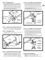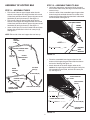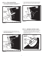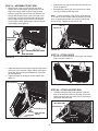
1
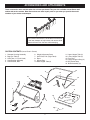
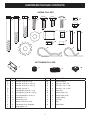
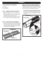
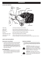
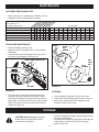
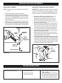
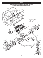
Owner's Manual
®
42" HIGH PERFORMANCE
LAWNSWEEPER
STOP
DO NOT RETURN TO STORE
For Missing Parts or Assembly
Questions Call 1-866-576-8388
Model No's. 486.242221, 486.242241
CAUTION:
Before using this product, read this
manual and follow all Safety Rules
and Operating Instructions.
•
•
•
•
•
Safety
Assembly
Operation
Maintenance
Parts
Sears, Roebuck and Co., Hoffman Estates, IL 60179 U.S.A.
www.sears.com/craftsman
PRINTED IN U.S.A.
FORM NO. 40734 Rev (06/11/09)
TABLE OF CONTENTS
Maintenance Schedule................................................... 13
Storage........................................................................... 13
Service and Adjustments................................................ 14
Troubleshooting.............................................................. 14
Repair Parts Illustration.................................................. 15
Repair Parts List............................................................. 16
Parts Ordering/Service.....................................Back Cover
Safety Rules..................................................................... 1
Warranty........................................................................... 2
Accessories and Attachments.......................................... 3
Carton Contents............................................................... 3
Full Size Hardware Chart................................................. 4
Sweeper Assembly Instructions....................................... 5
Hopper Assembly Instructions.......................................... 7
Operation........................................................................ 12
WARRANTY
CRAFTSMAN FULL WARRANTY
When operated and maintained according to all supplied instructions, if this Craftsman product fails due to a defect in material
or workmanship within one year from the date or purchase, return it to any Sears store or other Craftsman outlet in the United
States for free replacement.
This warranty applies for only 90 days from the date of purchase if this product is ever used for commercial or rental purposes.
This warranty does not include items considered to expendable parts that can wear out from normal use within the warranty
period.
This warranty gives you specific legal rights, and you may also have other rights which vary from state to state.
Sears, Roebuck and Co., D817WA, Hoffman Estates, IL 60179
DO NOT RETURN TO STORE for Missing Parts or Assembly Questions
Call 1-866-576-8388 Attachment Hotline
SAFETY
Any power equipment can cause injury if operated improperly or if the user does not understand how to operate the equipment.
Exercise caution at all times, when using power equipment.
6. Vehicle braking and stability may be affected with
the attachment of this sweeper. Do not fill sweeper
to maximum capacity without checking the capability
of the towing vehicle to safely pull and stop with the
sweeper attached. Stay off of steep slopes.
7. Stop and inspect vehicle and sweeper for damage
after striking an object. Repair any damage before
continuing operation.
8. Keep sweeper away from fire. Excessive heat can
damage the brushes and hopper bag and could cause
the bag and its contents to burn.
9. Before storing the sweeper, always empty the hopper
bag to avoid spontaneous combustion.
10.Follow maintenance and lubrication instructions as
outlined in the maintenance section of this manual.
1. Read the vehicle and sweeper owners manuals and
know how to operate your vehicle and sweeper before
using this sweeper attachment. Always instruct other
users before they operate the sweeper.
2. Do not permit children to operate sweeper.
3. Do not permit anyone to ride on sweeper.
4. Never attach the hopper rope to any part of your body
or clothing! Never hold onto the rope while towing the
sweeper! Attach the rope to the towing vehicle to keep
it away from wheels and rotating parts.
5. Operate the sweeper at reduced speed on rough
terrain, near ditches and on hillsides to prevent loss of
control.
Look for this symbol to point out important safety precautions. It means — Attention!!
Become alert!! Your safety is involved.
The model and serial numbers will be found on a decal
attached to the lawnsweeper.
You should record both the serial number and the date of
purchase and keep in a safe place for future reference.
MODEL NUMBER:
SERIAL NUMBER:
DATE OF PURCHASE:
2
486.242221, 486.242241
____________________
____________________
ACCESSORIES AND ATTACHMENTS
These accessories were available when the unit was purchased. They are also available at most Sears retail
outlets and service centers. Most Sears stores can order repair parts for you when you provide the model
numbers of your tractor and sweeper
The Front Mount Dethatcher, Model 486.24219 attaches
to the lawn sweeper to help loosen and remove dead
grass and thatch from the lawn while sweeping.
CARTON CONTENTS (Loose Parts in Carton)
1.
2.
3.
4.
5.
Sweeper Housing Assembly
Bag Arm Tube (2)
Hitch Tube, L.H. (Left Hand)
Hitch Bracket Assembly
Hitch Bracket, Bent
11.Upper Hopper Tube (2)
12.Lower Hopper Tube (2)
13.Pivot Rod
14.Hopper Support Strap (2)
15.Bag Frame Strap
16. Brush Assembly (2)
6. Height Adjustment Strap
7. Hitch Tube, R.H. (Right Hand)
8. Rope
9. Hopper Bag
10.Rear Hopper Tube (2)
10
11
13
12
11
16
10
2
1
14
12
7
9
15
6
2
4
5
8
3
3
HARDWARE PACKAGE CONTENTS
SHOWN FULL SIZE
A
B
C
D
E
H
G
F
I
L
N
K
O
P
Q
M
J
R
S
NOT SHOWN FULL SIZE
T
ref
qty
A
2
B
C
U
V
description
ref
qty
description
Hex Bolt, 5/16-18 x 3" Lg.
M
1
Spacer Bushing
3
Hex Bolt, 5/16-18 x 2-1/4" Lg.
N
2
Clevis Pin, 3/8" x 1/2"
3
Hex Bolt, 5/16-18 x 1-3/4" Lg.
O
4
Clevis Pin, 1/4" x 1-1/8"
D
4
Hex Bolt, 1/4-20 x 1"
P
2
Clevis Pin, 1/4" x 1-3/4"
E
1
Carriage Bolt, 5/16-18 x 1" Lg.
Q
2
Palnut, 3/8"
F
4
Carriage Bolt, 5/16-18 x 3/4" Lg.
R
1
Hairpin Cotter, 1/8"
G
4
Curved Head Bolt, 1/4-20 x 1"
S
8
Hairpin Cotter, 3/32"
H
8
Nylock Nut, 1/4"
T
4
Hopper Clamp
I
12
Nylock Nut, 5/16"
U
2
Vinyl Cap
J
1
Washer, Tooth Lock 5/16"
V
1
Grip
K
2
Flat Washer, 5/16" Standard
W
1
Plastic Knob
L
2
Hitch Spacer, 3/4"
4
W
ASSEMBLY
TOOLS REQUIRED FOR ASSEMBLY
STEP 3 - ATTACH R.H. BRUSH ASSEMBLY
IMPORTANT: The overlap bristles at the bottom of each
brush help support the back side of the brush for better
sweeper performance. Be sure the sweeper is turned as
shown in figure 2 to correctly assemble the brushes.
(1)Hammer
(2)1/2" Wrenches
(2) 7/16" Wrenches
• Attach the brush assembly with the black brush retainer
to the right end of the brush shaft using two hex bolts
(D) and nylock nuts (H). The brush retainer marked with
black ink must be placed to the middle of the sweeper.
See figure 2.
STEP 1 - REMOVE PARTS FROM CARTON
• To protect painted parts, lay them on cardboard or a
mat.
• Remove the sweeper housing, the loose parts and the
hardware package from the carton. Lay out the parts
and hardware as shown on pages 3 and 4.
• Place the sheet of cardboard from inside the carton onto
your work surface to prevent scratching the sweeper.
NYLOCK NUT (H)
WELDED BRACE
STEP 2 - IDENTIFY BRUSH ASSEMBLIES
HEX BOLT (D)
• Each brush assembly has one brush retainer marked
with either red or black ink. Lay out the brush assemblies
as shown so that the brush retainers marked with ink
are in the middle with the black one on your right and
the red one on your left. See figure 1.
BRUSH
RETAINER
MARKED
BLACK
BRUSH RETAINER
MARKED BLACK
BRUSH RETAINER
MARKED RED
OVERLAP
BRISTLES
FIGURE 2
OVERLAP BRISTLES
FIGURE 1
5
STEP 4 - ATTACH L.H. BRUSH ASSEMBLY
STEP 6 - ASSEMBLE RIGHT HITCH TUBE
• Attach the brush assembly with the red brush retainer
to the left end of the brush shaft using two hex bolts (D)
and nylock nuts (H). The brush retainer marked with red
ink must be placed to the middle of the sweeper. See
figure 3.
• Turn a wheel to rotate the brushes. (The wheels drive
the brushes in one direction only.) The overlap bristles
should be on the back side of the brush as it rotates.
• Hold the right hitch tube against the right side of the
sweeper so that the "76R" on the tube faces toward
the sweeper. Attach the hitch tube using one hex bolt
(C) and nylock nut (I). Do not tighten yet. See figure 5.
HEX BOLT (C)
NYLOCK NUT (I)
HOUSING
MARKED “R”
HEX BOLT (D)
TUBE
MARKED
“76R”
BRUSH RETAINER
MARKED RED
NYLOCK NUT (H)
HITCH TUBE (R.H.)
FIGURE 5
FIGURE 3
STEP 7 - ASSEMBLE HEIGHT ADJ. STRAP
STEP 5 - ASSEMBLE LEFT HITCH TUBE
• Attach the height adjustment strap to the hitch tube
using a hex bolt (B), the spacer bushing (M), a flat
washer (K) and a nylock nut (I). See figure 6. Do not
tighten yet.
• The hitch tubes are stamped with a "77L" for the
left tube and a "76R" for the right tube. The sweeper
housing is marked with an "L" on the left with side
and an "R" on the right side. See figures 4 and 5.
• Hold the left hitch tube against the left side of the
sweeper so that the "77L" on the tube faces away
from the sweeper. Attach the hitch tube using two
hex bolts (C) and nylock nuts (I). Do not tighten yet.
See figure 4.
HEIGHT ADJ. STRAP
SPACER
BUSHING (M)
NYLOCK NUT (I)
FLAT WASHER (K)
HEX BOLT (C)
HEX BOLT (B)
HOUSING
MARKED “L”
TUBE
MARKED
“77L”
FIGURE 6
HITCH TUBE (L.H.)
FIGURE 4
6
NYLOCK NUT (I)
STEP 8 - ASSEMBLE KNOB
STEP 12a - ASSEMBLE HITCH BRACKETS
• Place the height adjustment strap to the inside of the
height adjustment handle. Place the star washer (J)
between the height adjustment strap and the height
adjustment handle. Insert the carriage bolt (E) through
the strap, the star washer and the handle. Assemble
the flat washer (K) and the plastic knob (W) onto the
end of the bolt and tighten. See figure 7.
HEIGHT
ADJ.
STRAP
• If the tractor hitch is less than 10" above the ground,
assemble the hitch brackets as shown in figure 9. 10"
Insert two hex bolts (B) through the brackets, with
the rear hex bolt between the cross bolts in the hitch
tubes. Secure the hex bolts (B) with two nylock nuts
(I). Do not tighten yet. See figure 9.
• Assemble the two spacers (L) onto the hitch pin and
secure the pin with the hairpin cotter (R). See figure 9.
HEIGHT
ADJ.
HANDLE
HEX BOLTS (B)
HITCH BRACKET
ASSEMBLY
FLAT WASHER (K)
KNOB (W)
CARRIAGE
BOLT (E)
SPACERS (L)
STAR WASHER (J)
NYLOCK NUTS (I)
FIGURE 7
BENT HITCH
BRACKET
HAIRPIN COTTER (R)
FIGURE 9
STEP 9 - FASTEN HITCH TUBES TOGETHER
• Fasten the hitch tubes together using two hex bolts (A)
and nylock nuts (I). See figure 8. Do not tighten yet.
STEP 12b - ASSEMBLE HITCH BRACKETS
• If the tractor hitch is 10" or more above the ground,
assemble the hitch brackets as shown in figure 10. Insert two hex bolts (B) through the brackets, with
the rear hex bolt between the cross bolts in the hitch
tubes. Secure the hex bolts (B) with two nylock nuts
(I). Do not tighten yet. See figure 10.
• Assemble the two spacers (L) onto the hitch pin and
secure the pin with the hairpin cotter (R). See figure 10.
STEP 10 - ASSEMBLE GRIP
• Assemble the grip (V) onto the end of the height
adjustment handle as shown in figure 8.
HEX BOLT (A)
HEX BOLTS (B)
GRIP (V)
HAIRPIN
COTTER (R)
BENT HITCH
BRACKET
SPACERS (L)
NYLOCK NUT (I)
HITCH
BRACKET
ASSEMBLY
FIGURE 8
NYLOCK NUTS (I)
FIGURE 10
STEP 11 - MEASURE TRACTOR HITCH HEIGHT
• Use the mark along the side of this page to measure
the height of the tractor hitch. The mark is 10" from
the bottom of the page. If the tractor hitch is less than
10" above the ground, go to STEP 12a. If the tractor
hitch is 10" or more above the ground, go to STEP 12b.
STEP 13 - TIGHTEN BOLTS
• Tighten the four bolts assembled in steps 5, 6 and 7.
Tighten the two bolts assembled in step 9.
Tighten the two bolts assembled in step 12a or 12b.
7
ASSEMBLY OF HOPPER BAG
STEP 15 - ASSEMBLE TUBES TO BAG
• Unfold the hopper bag, reverse the fold of the mesh
wind screen and then lay the bag out flat with the wind
screen on top.
• Insert the ends of the assembled upper hopper tubes
down through the stitched sleeves in the sides of the
hopper bag and then slide the tubes back underneath
the wind screen. See figure 12.
STEP 14 - ASSEMBLE TUBES
• Fit the ends of the two upper hopper tubes into the
ends of a rear hopper tube. Align the holes in the ends
of the tubes and secure them in place using two curved
head bolts (G) and nylock nuts (H). See figure 11.
• Fit the ends of the two lower hopper tubes into the
ends of a rear hopper tube. Align the holes in the ends
of the tubes and secure them in place using two curved
head bolts (G) and nylock nuts (H). See figure 11.
• Insert a clevis pin (O) from the outside into each lower
hopper tube and secure it with a hair cotter pin (S).
See figure 11.
STITCHED SLEEVE
UPPER
HOPPER
TUBE
NOTE: Either side of the rear hopper tube can face up.
REAR
HOPPER
TUBE
HOPPER
BAG
BOTTOM
CURVED HEAD
BOLT (G)
NYLOCK
NUT (H)
FIGURE 12
UPPER
HOPPER
TUBE
REAR
HOPPER
TUBE
• Place the assembled lower hopper tubes into the
bottom of the hopper bag and then slide the tubes to
the back of the bag. See figure 13.
• Attach the ends of the lower hopper tubes to the
inside of the upper hopper tubes using two clevis pins
(N) inserted from the inside, and two hair cotter pins
(S). See figure 13.
NYLOCK
NUT (H)
CLEVIS PIN (O)
UPPER HOPPER
TUBE
CURVED HEAD
BOLT (G)
HAIR COTTER
PIN (S)
LOWER
HOPPER TUBE
HAIR COTTER PIN (S)
FIGURE 11
LOWER HOPPER TUBE
CLEVIS PIN (N)
HOPPER BAG
BOTTOM
FIGURE 13
8
STEP 16 - ATTACH BAG BOTTOM
• Fold the bag flaps around the lower hopper tubes and
attach to the bag bottom using the snaps. See figure
16.
• Insert the bag frame strap into the stitched sleeve at
the front edge of the bag bottom. See figure 14.
BAG FRAME STRAP
STITCHED
SLEEVE
SNAP
FLAP
FIGURE 16
FIGURE 14
STEP 17 - ASSEMBLE HOPPER CLAMPS
• Assemble two hopper mount clamps (T) over the hole
in the middle of each upper hopper tube using two
carriage bolts (F) and two nylock nuts (I). Tighten only
finger tight. See figure 17.
• Assemble the bag frame strap to the holes in the
lower hopper tubes using two clevis pins (O) and hair
cotter pins (S). See figure 15.
BAG FRAME STRAP
5/16" x 3/4"
CARRIAGE
BOLT (F)
HAIR COTTER
PIN (S)
HOPPER
MOUNT
CLAMP (T)
CLEVIS PIN (O)
UPPER
HOPPER
TUBE
FIGURE 17
FIGURE 15
9
5/16" NYLOCK
NUT (I)
STEP 18 - ASSEMBLE PIVOT ROD
• Assemble a vinyl cap (U) onto each bag arm tube as
shown in figure 20.
• Assemble two palnuts (Q) onto the ends of the pivot
rod using a hammer. See figure 20.
• Slide the end of the pivot rod through the upper
hopper tube and the hopper mount clamps on one
side of the hopper. Place a hopper support strap
and then a bag arm tube onto the rod. Slide the rod
through the stitched sleeve at the front edge of the
wind screen, and then place another bag arm tube
and a hopper support strap onto the rod. Slide the
rod through the other upper hopper tube and hopper
mount clamps. See figure 18.
HINT: To ease assembly of the palnuts, place the bag
on its side on a solid surface. With the bottom end of the
pivot rod against the surface, tap a palnut onto the top
end of the rod. Repeat for other end of rod.
CAP (U)
PALNUT (Q)
MOUNTING CLAMP
WIND SCREEN
MOUNTING CLAMP
HOPPER BAG
PIVOT ROD
FIGURE 20
HOPPER SUPPORT STRAP
BAG ARM TUBE
STEP 19 - ATTACH ROPE
• Secure the rope to the center of the upper rear hopper
tube as shown in figure 21.
FIGURE 18
• Attach the bottoms of the hopper support straps to the
clevis pins (O) in the lower hopper tubes, securing the
straps with the previously assembled hair cotter pins
(S). See figure 19.
• Tighten the nuts on the hopper mount clamps. See
figure 19.
MOUNTING CLAMP
TIGHTEN NUTS
FIGURE 21
STEP 20 - ATTACH HOPPER BAG
• To attach the hopper bag to the sweeper, slide the
ends of the bag arm tubes into the ends of the hitch
tubes and secure with two clevis pins (P) and hairpin
cotters (M). See figure 22.
BAG ARM TUBE
CLEVIS PIN (P)
CLEVIS PIN (O)
HAIR COTTER
PIN (S)
HAIRPIN
COTTER (S)
FIGURE 19
10
FIGURE 22
ATTACHING SWEEPER HITCH TO TRACTOR
BRUSH HEIGHT ADJUSTED
APPROXIMATELY MID-WAY
• Place the tractor and sweeper on a flat level surface.
• Set the sweeper height adjustment handle to about the
middle of its adjustment range.
• Attach the sweeper hitch to the tractor hitch, arranging
the 3/4" spacers in one of six possible combinations as
shown in GROUP A and GROUP B diagrams below.
IMPORTANT: To obtain the best performance from your
sweeper, arrange the spacers so that the sweeper bag is
approximately level with the ground and approximately 5"
to 7" off the ground as shown in figure 23.
APPROXIMATELY LEVEL
(5" to 7" FROM SURFACE)
FIGURE 23
GROUP "B" - For vehicles with hitches
having 10" to 13" ground clearance.
GROUP "A" - For vehicles with hitches
having 8" to 10" ground clearance.
HITCH BRACKET MOUNTED
ABOVE HITCH TUBES
HITCH BRACKET MOUNTED
BELOW HITCH TUBES
BLACK LINE IS TRACTOR HITCH
BLACK LINE IS TRACTOR HITCH
11
OPERATION
KNOW YOUR SWEEPER
HEIGHT
ADJUSTMENT
STRAP
HEIGHT
ADJUSTMENT
HANDLE
BAG ARM TUBE
PIVOT ROD
WINDSCREEN
HOPPER
ROPE
HITCH
BRACKETS
HOPPER BAG
Hopper Bag
Collects grass clippings, leaves and debris.
Hopper Rope Permits dumping of hopper bag from driver's seat.
Windscreen
Helps prevent collected material from being blown out of hopper bag.
Bag Arm Tubes Connects the hopper bag to the sweeper housing.
Pivot Rod
Allows hopper bag to tilt forward to dump material.
Height Adjustment Handle
Adjusts the operating height of the sweeper.
Height Adjustment Strap
Holds the height adjustment handle in position when locked.
Hitch Bracket
Connects the sweeper to the towing vehicle. Adjusts for various height tractor hitches.
HOW TO USE YOUR SWEEPER
DUMPING OF SWEEPER
• Your sweeper can be dumped easily without getting
off of the rider or tractor. Simply pull the rope forward
to dump the hopper. Always empty hopper after each
use.
BRUSH HEIGHT ADJUSTMENT
• To adjust your sweeper brushes to the best operating
height, loosen the adjustment knob and push down
on the height adjustment handle to raise the brush, or
push up on the handle to lower the brush. See figure
19. Best adjustment is when the brush setting is 1/2"
down into the grass. Always mow the grass to an even
height before sweeping.
CAUTION: Never attach the hopper rope
to any part of your body or clothing! Never
hold onto the rope while towing the sweeper!
Attach the rope to the towing vehicle to keep
it away from wheels and rotating parts.
SWEEPING SPEED
• Try a starting speed of approximately 3 m.p.h. (third
gear on most tractors). Depending on the conditions,
it may be necessary to adjust the sweeping speed in
order to achieve best results.
CAUTION: Keep sweeper away from fire.
Excessive heat can damage the brushes and
hopper bag and could cause the bag and its
contents to burn.
12
MAINTENANCE
CUSTOMER RESPONSIBILITIES
• Read and follow the maintenance schedule and the
procedures listed in the maintenance section.
MAINTENANCE SCHEDULE
Fill in dates as you
complete regular service.
s
se e
e
ar
h u h us ear son orag ye
c
y
ea st
ea ac
wo
re er e ice a ry s fore ry t
o
f
e
e
t
Tw Ev Be Ev
Be Af
Check for loose fasteners
X
Check for worn or damaged parts X
Lubricate brush shaft bearings
Lubricate wheel bearings
Clean Sweeper
Clean/Lubricate chain and sprockets X
X
X
X
X
X
SCHEDULED MAINTENANCE
Service Dates
COVER
• Clean the sweeper after each use.
• Inspect for worn or damaged parts, such as brushes
and wheels.
• Lubricate the brush shaft bearing twice a year with a
few drops of light weight oil. See figure 24.
CLEAN
AND
GREASE
HEIGHT ADJUSTMENT SLOT
HEX
LOCK
NUT
FLAT
WASHER
OIL BEARINGS HERE
FLAT WASHER
HUB CAP
FIGURE 25
HEX BOLT
FIGURE 24
CLEANING
• Every two years, remove the wheels and clean the
sprockets, chains and gears found inside the wheel
housing. After cleaning, lubricate with an even coat of
light grease. To remove the wheel, pop off the hub cap
using a screwdriver and remove the lock nut and flat
washer. See figure 25.
• Clean sweeper housing with a soft brush or cloth.
• Clean debris from hopper bag with a brush or broom.
• Remove any material which has wrapped around
brushes or ends of brush shaft.
STORAGE
• Clean the sweeper and hopper bag thoroughly to help
prevent rust and mildew.
• To collapse the hopper bag for storage, remove the two
hopper support rods from the rear of the hopper.
• Store in a dry area.
CAUTION:Before storing the sweeper,
always empty the hopper bag to avoid
spontaneous combustion.
13
SERVICE AND ADJUSTMENTS
BRUSH REPLACEMENT
SPROCKET, CHAIN AND PAWL SERVICE
NOTE: Brush replacement should be done one brush at a time.
IMPORTANT: Do not remove both wheels at the same
time to avoid mixing of parts. (The R.H. and L.H. ratchet
sprockets are not interchangeable.) Make notes on the
position of washers and snap rings during disassembly.
• Remove the hopper bag from the sweeper.
• Loosen the hex bolts and lock nuts on two single
brush retainers which clamp one brush to the double
brush retainers. Do Not loosen or remove the bolts
which fasten the double brush retainers to the brush
shaft. See figure 26.
• Slide the brush out of the retainers, noting on which
side of the brush the bristles overlap. See figure 26.
• Install new brush, making sure the bristles overlap on
the same side of the brush as before. See figure 26.
• Remove the dust cover by removing the two rivets
which fasten it to the wheel housing. (It is not
necessary to remove the dust cover if you are only
cleaning and lubricating the chain and sprockets.)
• Remove the retaining rings and washers which hold
the sprockets onto the shafts.
• Remove the chain and both sprockets, holding them in
position and sliding them off both of the shafts. (Look
for the drive pin, which may fall out of the brush shaft
when the ratchet sprocket is removed.) See figure 27.
• To reassemble, insert the drive pin through the hole
at the end of the brush shaft. Make sure the pin slides
back and forth easily in the shaft.
• Lightly grease both shafts and the chain, and fill the
ratchet sprocket with grease. Assemble the chain with
both sprockets back onto the shafts.
• Lightly grease the axle and then reassemble the wheel. The brushes should rotate only during forward rotation
of the wheel. If the brushes are driven (rotated) by both
forward and reverse rotation of the wheel, the drive pin
is jamming in the ratchet gear. Disassemble and clean
and lubricate the drive pin and ratchet gear.
BRUSH ROTATION
BRUSH
SHAFT
OVERLAP
BRISTLES
SINGLE
BRUSH
RETAINERS
DOUBLE BRUSH RETAINER
OVERLAP
BRISTLES
DUST COVER
GEAR SPROCKET
CHAIN
BRUSH ROTATION
RATCHET
SPROCKET
FIGURE 26
DRIVE PIN
FIGURE 27
TROUBLESHOOTING
Wheels skid when sweeping.
• Brushes set too low.
• Brushes are jammed
• Wheels are jammed.
14
• Adjust height till brushes are 1/2"
down into grass.
• Stop sweeper. Remove obstruction.
• Remove one wheel at a time to check
for obstruction or damage. Refer to
Service and Adjustments section.
NOTES
15
PARTS
REPAIR PARTS LIST FOR MODELS 486.242221, 486.242241
42" HIGH PERFORMANCE LAWNSWEEPER
43
70
42
74
73
71
44
43
70
10
42
52
59
74
17
54
75
46
44
53
53
47
46
75
45
48
14
75
72
44
56
55
72
3
56
40
15
16
20
C
17
39
59
19
18
D
27
11 13
12
59
C 33
28
6
8
B
14
31
55
30
28
E
26
38 23
35
25 26
20
29
24
41
28
34
49
57
65
B
66
D
58
64
67
A
1
32
4
A
60
63
75
37
21
37
E
58
2
62
63
61
76
9
59
51
22
59
16
77
7
5
68
50
69
REPAIR PARTS LIST FOR MODELS 486.242221, 486.242241
42" HIGH PERFORMANCE LAWNSWEEPER
ref
1
2
3
4
5
6
7
8
9
10
11
12
13
14
15
16
17
18
19
20
21
22
23
24
25
26
27
28
29
30
31
32
33
34
35
36
37
38
39
part
qty description
ref
no.
46776
1 Hitch Tube, R.H.
40
46777
1 Hitch Tube, L.H.
41
65885
1 Housing Assembly
42
49102
4 Screw, #12 x 1/2" Hex Head
43
142
1 Pin, Cotter 1/8" x 3/4" Lg.
44
68202
1 Height Adjustment Tube Ass'y.
45
43070
1 Washer, 3/8" Flat
46
C-9M5732 8 Rivet, Pop
47
43086
4 Lock Washer, 5/16"
48
43080
4 Bolt, Carriage 5/16-18 x 3/4"
49
62489
2 Brush Bushing Ass'y.
50
44232
2 Ball Bearing
51
1629-56
2 Retainer, Dust Cover
52
25847
1 Brush Shaft
53
46780
4 Brush, 42"
54
43012
8 Bolt, Hex 1/4-20 x 3/4" Lg.
55
47189
16 Nut, Nylock 1/4-20 Thread
56
23580
4 Retainer, Brush (Double)
57
23581
8 Retainer, Brush (Single)
58
44008
2 Washer, Flat 1-1/8" x .78" x .025"
59
62490
2 Sprocket / Gear
60
23573
2 Dust Cover
61
47046
2 Dowel Pin (Drive)
62
43655
2 Ring, Retaining 3/4"
63
716-0106
2 Ring, Retaining .594"
64
40001
14 Washer, Shim 1-1/8" x .594" x .025" 65
43182
4 Bolt, Hex 5/16-18 x 3/4" Lg.
66
141
6 Washer, Flat 1-1/2" x .375" x .062" 67
1540-31
4 Washer, Flat .78" x 1.25" x .06"
68
1038
2 Nut, Nylock 3/8-24 Thread
69
2674-32
2 Hub Cap
70
1650-1
2 Ring, Retaining (E-type)
71
43932
2 Bolt, Hex 3/8-24 x 3-1/2" Lg.
72
23400
2 Bushing, Spacer
73
43890
1 Sprocket, Ratchet R.H.
74
43889
1 Sprocket, Ratchet L.H. (not shown) 75
44137
4 Washer, 1/2" x 1" x .02"
76
44542
2 Chain, Roller
77
43661
4 Bolt, Hex 1/4-20 x 1" Lg.
17
part
no.
65667
65668
49765
47477
48726
24189
25813
43737
49768
24979
23687
24192
23331
49766
46823
44985
45088
46782
43224
47810
23625
43720
44326
43081
43084
43943
44732
49493
23368
43343
44917
43978
48365
48366
44481
43055
46867
44230
40734
qty description
1
1
2
2
2
1
2
1
1
1
1
1
4
2
1
2
4
2
3
12
1
1
1
2
3
1
1
1
2
1
2
4
4
2
2
8
2
1
1
Housing, Wheel Drive Ass'y. L.H.
Housing, Wheel Drive Ass'y. R.H.
Tube, Upper Hopper Frame
Tube, Rear Hopper Frame
Tube, Lower Hopper Frame
Strap, Bag Frame
Strap, Hopper Support
Hopper Rope
Hopper Bag
Strap, Height Adjustment
Bracket, Hitch
Bracket, Hitch (Straight)
Hopper Mount Clamp
Tube, Bag Arm
Pivot Rod, Hopper Bag
Wheel & Tire Ass'y. (with bearings)
Wheel Bearing
Bolt, Hex 5/16-18 x 3" Lg.
Bolt, Hex 5/16-18 x 2-1/4" Lg.
Nut, Nylock 5/16-18 Thread
Spacer, .38" x .62" x .27" L
Knob, Wing 5/16-18 Thread
Bolt, Carriage 5/16-18 x 1" Lg.
Washer, Flat 5/16" Std. Wrt.
Bolt, Hex 5/16-18 x 1-3/4" Lg.
Grip, Height Adjust
Washer, Tooth Lock 5/16"
Pin, Hitch
Tube, Hitch Spacer
Hairpin Cotter, 1/8"
Palnut, 3/8"
Curved Head Bolt, 1/4-20 x 1"
Pin, Clevis 1/4" x 1-1/8"
Pin, Clevis 3/8" x 1/2"
Cap, Vinyl
Hairpin Cotter, 3/32" #3
Pin, Clevis 1/4" x 1-1/2" Lg.
Spring, Hitch Pin
Owners Manual
18
19
Get it fixed, at your home or ours!
Your Home
For expert troubleshooting and home solutions advice:
www.managemyhome.com
For repair – in your home – of all major brand appliances,
lawn and garden equipment, or heating and cooling systems,
no matter who made it, no matter who sold it!
For the replacement parts, accessories and
owner’s manuals that you need to do-it-yourself.
For Sears professional installation of home appliances
and items like garage door openers and water heaters.
1-800-4-MY-HOME®
(1-800-469-4663)
Call anytime, day or night (U.S.A. and Canada)
www.sears.com
www.sears.ca
Our Home
For repair of carry-in items like vacuums, lawn equipment,
and electronics, call anytime for the location of your nearest
Sears Parts & Repair Service Center
1-800-488-1222 (U.S.A.)
www.sears.com
1-800-469-4663 (Canada)
www.sears.ca
To purchase a protection agreement on a product serviced by Sears:
1-800-827-6655 (U.S.A.)
1-800-361-6665 (Canada)
Para pedir servicio de reparación
a domicilio, y para ordenar piezas:
Au Canada pour service en français:
1-888-SU-HOGAR®
1-800-LE-FOYER MC
(1-888-784-6427)
® Registered Trademark / TM Trademark / SM Service Mark of Sears Brands, LLC
® Marca Registrada / TM Marca de Fábrica / SM Marca de Servicio de Sears Brands, LLC
MC
Marque de commerce / MD Marque déposée de Sears Brands, LLC
(1-800-533-6937)
www.sears.ca
© Sears Brands, LLC