1
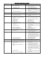
DIRECT VENT GAS
BASEBOARD HEATER
INSTALLATION AND
OPERATING INSTRUCTIONS
R
P/N 64900 /
MODEL NUMBERS
NAT. GAS
L.P. GAS
BBT53
BBT54
BBT103
BBT104
September 2004
R
INSTALLER MUST LEAVE THESE INSTRUCTIONS
WITH THE CONSUMER, HAVE THEM COMPLETE,
AND RETURN THE WARRANTY CARD.
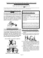
WARNING: If the information in these instructions are
not followed exactly, a fire or explosion may result
causing property damage, personal injury or loss of life.
•
•
•
•
-
Do not store or use gasoline or other flammable vapors
and liquids in the vicinity of this or any other appliance.
WHAT TO DO IF YOU SMELL GAS:
Do not try to light any appliance.
Do not touch any electrical switch; do not use any
phone in your building.
Immediately call your gas supplier from a neighbor’s
phone. Follow the gas supplier’s instructions.
If you cannot reach your gas supplier, call the
fire department.
INSTALLATION AND SERVICE MUST BE PERFORMED BY A QUALIFIED INSTALLER,
SERVICE AGENCY OR THE GAS SUPPLIER.
This appliance must be connected to an
electrical ground.
WARNING:
CONNECT TO 115V ELECTRICAL
POWER SUPPLY.
DO NOT CONNECT TO 220V
POWER SUPPLY.
U.S. PATENT #
5253635
CANADIAN PATENT #
2066870
WARNING: Operation of this furnace without the properly installed, factory furnished vent system could
result in Carbon Monoxide (CO) poisoning and possible death. For your safety, this furnace and the vent
system should be inspected at least annually by a qualified service person.
May be installed in an aftermarket, permanently located, manufactured home (mobile home) where not
prohibited by local codes. See owner’s manual for details. This appliance is not convertible for use with other
gases, unless a certified kit is used.
This unit is not approved for installation in greenhouses, or environments involving dusty, wet,
corrosive, or explosive conditions. Such conditions will invalidate the warranty and may create unsafe
conditions.
NOTE: Obstruction in the vent exhaust tube or air intake tube due to insects, small animals, debris,
etc. will prevent the heater from operating but DOES NOT constitute a warranty issue.
The State of Massachusetts requires that installation and service of a gas
appliance be performed by a plumber or gas fitter licensed in the
Commonwealth of Massachusetts.
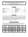
CONTENTS
Introduction…………………………….....
2
Specifications and Dimensions………...…..
2
Safety Rules……………………………..
3
Clearances………………………………. 4, 5
Location…………………………………
5
Installation………………………………. 6 - 10
Lighting Instructions……………………...
11
Gas Conversion.........................................
12
Burner Orifice…………………………..... 13
Wiring Diagram…………………………... 14
Removing Main Burner………………....… 13
Proper Burner Flame………………...…… 13
Sequence of Operation……………......….
15
Optional Kits………………………........16 - 20
Trouble Shooting…………………..…... 21 - 22
Parts Drawing…………………………..... 23
Parts List………………………………..... 24
Warranty………………………………..... 26
INTRODUCTION
THIS IS A GAS-FIRED, DRAFT INDUCED, POWER DEPENDENT, DIRECT VENT WALL FURNACE;
THAT WILL OPERATE SAFELY AND PROVIDE AN EFFICIENT SOURCE OF HEAT WHEN
INSTALLED, OPERATED AND MAINTAINED AS RECOMMENDED IN THESE INSTALLATION AND
OPERATING INSTRUCTIONS. READ THESE INSTRUCTIONS THOROUGHLY BEFORE INSTALLING,
SERVICING, OR USING THE APPLIANCE. IF YOU DO NOT UNDERSTAND ANY PART OF THESE
INSTRUCTIONS CONSULT LOCAL AUTHORITIES, OTHER QUALIFIED INSTALLERS, SERVICE
AGENCIES, THE GAS SUPPLIER OR THE MANUFACTURER.
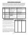
SPECIFICATIONS AND DIMENSIONS
Your Direct Vent Wall Furnace is shipped complete in one carton. This carton contains the furnace, vent
exhaust tube, air inlet tube, template with rough-in dimensions, installation and operating instructions, power
cord (consult electrical codes), ball-valve w/flex connector, and wall thermostat.
MODEL
NO.
INPUT
BTU/HR.
WIDTH DEPTH HEIGHT
BBT53
5,000 BTU
1.45 KW
5,000 BTU
1.45 KW
9,000 BTU
2.61 KW
9,000 BTU
2.61 KW
48”
122cm
48”
122cm
72”
183cm
72”
183cm
BBT54
BBT103
BBT104
5.375”
13.65cm
5.375”
13.65cm
5.375”
13.65cm
5.375”
13.65cm
9.375”
23.8cm
9.375”
23.8cm
9.375”
23.8cm
9.375”
23.8cm
Page 2
GAS
CONN.
TYPE
GAS
3/8”
NAT.
3/8”
L.P.
3/8”
NAT.
3/8”
L.P.
MAX. WALL
Thickness
16”
41cm
16”
41cm
16”
41cm
16”
41cm
MIN. WALL
Thickness
4”
10cm
4”
10cm
4”
10cm
4”
10cm
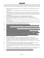
SAFETY RULES
The Direct Vent Gas Baseboard Heater and its components meet all applicable safety standards when installed as
directed in this manual. For safe installation and operation of your Direct Vent Gas Baseboard Heater, read all these
instructions before you begin. Failure to follow them exactly will void your warranty and may present a fire hazard.
1.
2.
3.
4.
5.
6.
7.
8.
9.
10.
11.
12.
13.
14.
15.
16.
17.
18.
19.
20.
21.
22.
23.
24.
Improper installation, adjustment, alteration, service, or maintenance can cause property damage, bodily
injury, or death.
Use in other than a residential application may result in unsatisfactory performance and may void the
warranty.
Follow all applicable codes and ordinances. If there are none, follow the latest edition of National Fuel
Gas Code ANSI Z223.1 A copy may be obtained from the CSA International, or the National Fire Protection Association, Batterymarch Park, Quincy, MA. 02269. In Canada, use latest edition of CAN1-B149
installation code.
DO NOT INSTALL THIS FURNACE IN A RECREATIONAL VEHICLE.
Do not operate baseboard heater unless it is connected to the factory supplied vent system.
Check the rating label attached to the baseboard heater to be sure it is equipped for the type gas you
intend to use.
Never use a match, candle, flame or other source of ignition to check for gas leaks. Use only soapy water
or liquid detergent.
Have your baseboard heater and vent system inspected at least annually by a qualified service technician.
Before cleaning or servicing, turn off the gas and allow heater to cool.
Do not operate baseboard heater without all components properly installed.
Due to high temperatures, the baseboard heater should be located out of traffic and away from furniture
and drapes.
Children and adults should be alerted to the hazard of high surface temperature and should be kept away
to avoid burns or clothing ignition.
Young children should be carefully supervised when they are in the same room with the baseboard heater.
Do not place clothing or other flammable material on or near the heater.
INSTALLATION AND REPAIR SHOULD BE DONE BY A QUALIFIED SERVICE PERSON.
THE BASEBOARD HEATER SHOULD BE INSPECTED BEFORE USE AND AT LEAST ANNUALLY BY A PROFESSIONAL SERVICE PERSON. More frequent cleaning may be required
due to excessive lint from carpeting, bedding material, etc. It is imperative that control compartments,
burner, and circulating air passageways of the heater be kept clean.
Do not install in a closet, alcove, or small hallway where the heater could be isolated from the space to
be heated by closing a door.
Do not put anything around the heater or vent that will obstruct the flow of combustion and
ventilation air. The flow of ventilation air through the upper and lower louvers must not be obstructed.
The appliance, when installed, must be electrically grounded in accordance with local codes or, in the
absence of local codes, with the latest edition of National Electrical Code, ANSI/NFPA 70. In Canada, use
CSA C22.1.
Never operate this heater without the burner sight glass in place or with the glass broken or missing.
If it is suspected that rising water may enter the heater, turn off the gas immediately.
Do not use the heater if any part has been under water. Immediately call a qualified service technician
to inspect the appliance and to replace any part of the control system and any gas control which has been
under water.
It is necessary to replace damaged gaskets or sealing material within the vent or air intake system. Failure
to do so may result in property damage, personal injury, loss of life or unsatisfactory performance.
The cabinet cover removed for servicing must be replaced prior to operating heater.
This heater must not be connected to a chimney flue.
Page 3
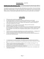
CLEARANCES
CLEARANCES TO COMBUSTIBLES
COMBUSTIBLE
CLEARANCE
Floor......................................
0 Inches (0 cm)
Right Side..............................
0 Inches (0 cm)
Left Side................................
0 Inches (0 cm)
Back......................................
0 Inches (0 cm)
Front...................................... 16 Inches (41 cm)
Ceiling.................................... 36 Inches (91 cm)
Draperies................................ 4 Inches (10 cm)
Vent........................................ 2.5 Inches (6.35 cm)
If the heater is installed directly
on carpeting, tile or other combustible material other than
wood flooring, the heater shall
be installed on a metal or wood
panel extending the full width
and depth of the heater.
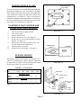
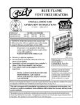
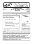
VENT CAP CLEARANCES
FIG. 1
OUTSIDE LOCATION FOR VENT OUTLET TERMINAL
A = Clearance above grade, veranda, porch, deck or balcony
(*12 inches [30cm] minimum)
B = Clearance to window or door that may be opened
(*6 inches [15 cm] minimum)
C = Clearance to permanently closed window (minimum 12
inches [30 cm] recommended to prevent condensation
on window)
D = Vertical clearance to ventilated soffit located above the
terminal within a horizontal distance of 2 feet [60 cm]
from the center-line of the terminal (18 inches [46 cm]
minimum)
E = Clearance to unventilated soffit (12 inches [30 cm]
minimum)
F = Clearance to outside corner (12 inches [30 cm]
minimum)
G = Clearance to inside corner (24 inches [60 cm]
minimum)
H = *Not to be installed above a meter / regulator assembly
within 3 feet [90 cm] horizontally from the center-line
of the regulator
I = Clearance to service regulator vent outlet (*6 feet [1.8 m]
minimum)
J = Clearance to non-mechanical air supply inlet to building
or the combustion air inlet to any other appliance (*12
inches [30 cm] minimum)
K = Clearance to a mechanical air supply inlet (*6 feet
[1.8 m] minimum)
L = † Clearance above paved side-walk or a paved driveway
located on public property (*7 feet [2.1 m] minimum)
M = Clearance under a veranda, porch, deck or balcony
(*12 inches [30 cm] minimum‡)
† A vent shall not terminate directly above a sidewalk or
paved driveway which is located between two single
family dwellings and serves both dwellings*.
‡ Only permitted if veranda, porch, deck or balcony is
fully open on a minimum of 2 sides beneath the floor.
* As specified in CGA B149 installation codes, NOTE:
local codes or regulations may require different
clearances.
Page 4
CLEARANCES - CONT’D.
RESIDENTIAL GARAGE INSTALLATION: Gas utilization equipment in residential garages shall be installed so that all burners and burner ignition devices are located not less than 18 inches [46 cm] above the floor.
Unit should be located or protected so it is not subject to damage by a moving vehicle. Use care in selecting a
good location within the garage. DO NOT locate the heater where heated air will be directed onto a nearby
parked vehicle. Paint may discolor or rubber may harden and crack. DO NOT allow open or closed containers
of paint, gasoline or other liquids having flammable vapors to be stored or used in the same area as the heater.
LOCATION
1.
2.
3.
4.
5.
6.
7.
8.
9.
This heater must be installed on an outside wall.
For efficient performance, locate heater as centrally as possible in the area to be heated.
Check outside wall where vent will exit, for proper clearances (See Figure 1), compliance with local
codes and clearances above grade. Also, consider exterior appearance, walkways, plantings, etc.
Check that a gas supply line is accessible.
Check that a 115 V. power supply circuit is accessible. (Do not use 220 volt current).
Installation must provide clearance for servicing heater.
If heater is installed in a basement, a 12” [30 cm] clearance must be maintained between ground level and
the vent intake pipe. Do not install heater where the vent will terminate in a window well or any opening
below ground level. Do not allow snow accumulation to build up within 12” [30 cm] of the vent air
intake pipe.
Clearances must be maintained providing adequate air circulation around the heater. A minimum of 16
inches [41 cm] must be maintained from the front of the heater to furniture, doors, etc.
Up to three baseboard heaters may be controlled by one thermostat (provided all three heaters are in
the same room with the thermostat).
THERMOSTAT LOCATION
1.
2.
3.
4.
Locate thermostat on an inside wall about 5 feet off the floor and 6 feet from the baseboard heater,
accessible to wiring, service and adjustment, in a frequently used room such as a living room, rec room,
etc.
Do not locate thermostat in unusual heating conditions such as in sunlight, close to lamps, TV sets,
radiators, registers, or other heat producing appliances.
Do not locate thermostat in unusual cooling conditions such as on an outside wall, or one separating an
unheated room, or in drafts from stairwells, doors, windows, etc.
Do not locate thermostat where air circulation is poor such as in a corner, alcove, over furniture or the
wall behind an open door.
Page 5
OPTIONAL KITS
For special installation applications and modifications, the following kits are available from your local dealer. To
ensure safe, efficient operation of your Direct Vent Gas Baseboard be sure to use only authorized kits.
Table 1: Special adaptation and modification kits available for use with the Direct Vent Baseboard Heaters.
MODEL #
VWSK5/10
DESCRIPTION
Vent Weather Seal Kit
CONTENTS
2” diameter PVC pipe, external wall seal, O-ring, 2 PVC straps,
PVC glue, instructions.
VRK5/10
Vent Riser Kit
Wall mount plate, 21-1/2” stainless steel vent riser, instructions
SVCK5/10
Side Valve Concealer Kit
4” cabinet extension, wall plate, screws, instructions
BVCK5/10
Bottom Valve Concealer Kit
4” cover, wall plate, screws, instructions
INSTALLATION
WARNING:
Failure to follow these instructions carefully could result in poor performance, property damage,
personal injury, or loss of life.
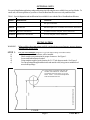
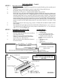
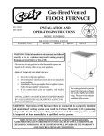
STEP 1.
LOCATE VENT OPENING (Requires a 2-1/2” hole when not using vent weather seal kit).
Select area on wall where heater will be installed.
Check outside vent termination for proper clearances. See Figure 1.
Locate studs behind heater location.
Using template supplied, mark location for 2-1/2” hole between studs. See Figure 2.
Cut vent openings through both the inside and outside walls, being sure to maintain level
across both openings.
VENT HOLE LOCATION FOR THE AIR
INTAKE AND EXHAUST TUBES FOR
STANDARD INSTALLATION 2-1/2” DIA.
HOLE. NOTE: 3” DIA. HOLE REQUIRED
FOR WEATHER SEAL KIT.
RIGHT END OF HEATER
11-3/8”
7-3/4”
a)
b)
c)
d)
e)
FLOOR
FLOOR
Page 6
FIGURE 2
INSTALLATION - Cont’d.
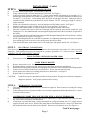
STEP 2.
a)
ROUGH IN GAS SUPPLY – (See Figure 3)
Select the bottom, rear or right side to bring the factory supplied flexible gas line assembly out of
the heater.
The valve must be connected only by means of a pipe union of the ground joint type.
Mr. Installer, hold gas valve when connecting gas supply line.
Install at least a 3/8” gas line. Contact local gas supplier if any questions.
Install a drip leg in gas supply line immediately upstream from the gas connection to heater, (see
local codes), and provide a 1/8” N.P.T. plugged tapping, accessible for test gauge connection and a
individual manual shut off valve accessible within room where heater is installed. The heater and
its individual shut off valve must be disconnected from the gas supply piping system during any
pressure testing of that system at test pressures in excess of ½ psig (3.5Pa). The heater must be
isolated from the gas supply piping system by closing its individual manual shut off valve during any
pressure testing of the gas supply piping system at test pressures equal to or less than ½ psig
(3.5Pa).
Test all connections for leaks using a soapy solution. NEVER USE AN OPEN FLAME TO TEST
FOR LEAKS.
The maximum inlet gas supply pressure for natural and L.P./Propane gas is ½ p.s.i. or 14” w.c.
The minimum inlet as supply pressure for the purpose of adjustment is 4.5” w.c. for natural gas
and 11.0” w.c. for L.P./Propane gas.
b)
c)
d)
e)
f)
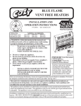
STEP 3.
a)
PREPARING TO INSTALL THE
BASEBOARD HEATER
Open the carton and carefully remove the Direct
Vent Baseboard Heater.
Remove the cover of the baseboard heater’s
cabinet by removing the screws at the bottom
front of the cover. (See Figure 4.)
Make sure that all of the components illustrated
have been included.
b)
c)
YOU SHOULD HAVE:
• 1 – Baseboard Heater
• 1 – Exhaust Tube
• 1 – Air Intake Tube
• 1 – 4” [10 cm] Stainless steel flexible
connector with a manual shut-off valve
• 1 – Template to locate venting and
mounting positions (in package with
manual)
• 1 – Vent Sealing Gasket
• 1 – Manual
• 1 – Weather Seal
• 1 - Wall thermostat w/wire & staples
BASEBOARD CABINET
2” FROM END OF CABINET
FLOOR
1/4”
[48” - 5M BTU] - - - [72” - 9M BTU]
MANUAL SHUT OFF VALVE WITH 1/8” NPT PLUGGED TAPPING
DRIP LEG
FLEX LINE BALL VALVE MUST BE
ABOVE FLOOR
GAS SUPPLY
1/2” BLACK IRON PIPE
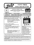
FIGURE 3
Exhaust Tube
FIGURE 4: COMPONENTS OF THE
DIRECT VENT GAS BASEBOARD
HEATER
Indoor Intake Gasket
Weather
Seal
Air Intake Tube
Screws
Flex Line Ball Valve
Gas Baseboard Heater
Cabinet
Cover
Screws
48” - BBT53 & BBT54
72” - BBT103 & BBT104
Page 7
FIGURE 4
CUT THE AIR INTAKE 1-1/2” LONGER
THAN THE WALL THICKNESS (Do not
cut to less than 5-1/2”)
1-1/2”
1”
BASEBOARD
HEATER
Measure
Wall
Thickness
EXHAUST
TUBE
CUT THE EXHAUST TUBE
FROM THE UNTHREADED
END, USE THE CUT-OFF
SECTION FROM THE AIR
INTAKE TUBE AS A GUIDE
(Do not cut to less than 7-1/2”)
THREADED
END
AIR INTAKE
TUBE
EXTERIOR WALL
FIGURE 5
FIGURE 6
BASEBOARD
HEATER
HEATER MUST BE LEVEL
USE THE MOUNTING HOLES PROVIDED
IN THE CASING BACK TO MOUNT
BASEBOARD TO WALL. AT LEAST
ONE MOUNTING HOLE MUST ALIGN
WITH A WALL STUD.
FIGURE 7
Wire Nuts
Green Wire
(Ground Wire)
Black Wire
(Electric
Connection)
Junction Box Cover
WEATHER
SEAL
FIGURE 8
Black wire
to L2 on
control
module
Black wire to L1
on control
module
White Wire
(Electric
Connection)
Electric Power Supply
FIGURE 9
Page 8
INSTALLATION - Cont’d.
STEP 4.
a)
b)
c)
d)
e)
f)
g)
h)
i)
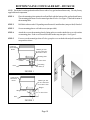
INSTALLING THE BASEBOARD HEATER
Use only factory supplied parts. Do not modify in any way.
Using a measuring tape, measure the thickness of the wall. See Figure 5.
Using a tube cutter, cut the air intake pipe 1.5” [3.8 cm] longer than the wall thickness (no less than 5-1/2”).
Measuring from the threaded end, cut the vent exhaust pipe 3.0” [7.62 cm] longer than the wall thickness (no
less than 7.5” {19.05 cm}). After cutting, check the inside of both pipes for burrs. Both pipes must be
smooth and clean without any reduction to the inside diameter. NOTE: Correct pipe length is critical to
proper operation.
Attach vent exhaust tube to heater by screwing threaded end into inducer outlet. See Figure 5.
Attach air intake pipe to back of heater using six #8 screws provided. See Figure 6.
Slide the indoor intake gasket over the air intake pipe and against the back of the heater.
Place the vent tubes into center of the hole cut through wall and slide the entire heater towards the wall,
feeding the 115 V. line and thermostat wires through the appropriate holes in the rear, bottom, or right side of
the heater.
Level and secure heater to wall with screws (not provided) through mounting holes in back of heater. Anchors
(not provided) may be required. See Figure 7.
NOTE: Mounting the heater on a wall that is not plumb or over tightening mounting screws may cause undue
stress which may result in excessive noise during warm-up and cool-down.
From outside the house, slide weather seal over air intake pipe and against outside wall. See Figure 8.
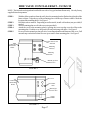
STEP 5. ELECTRICAL CONNECTIONS
If this heater is replacing a 220 volt electric baseboard heater, the circuit must be converted to 115 volt by a licensed
electrician. This appliance must only be connected to a properly grounded 115 V. electrical circuit. DO NOT
CONNECT TO 220 VOLT SUPPLY CIRCUIT.
a)
USING FACTORY INSTALLED POWER CORD
Unwrap power cord and plug directly into nearest 115 volt electrical outlet. Do not use extension cord.
a)
b)
c)
d)
e)
f)
HARD WIRING HEATER
Remove junction box cover. See Figure 9.
Disconnect factory wired power cord, remove power cord from junction box and discard.
Install electrical wiring into junction box through appropriate knockout. Secure with strain relief fitting supplied.
Connect wires to factory installed wires in junction box. Secure with wire nuts provided.
Secure ground wire under screw holding junction box to heater back. See Figure 9.
Replace and secure junction box cover.
CAUTION:
Label all wires prior to disconnection when servicing controls. Wiring errors could cause improper or
dangerous operation. Verify proper operation after servicing.
STEP 6.
a)
b)
c)
d)
THERMOSTAT CONNECTION
This heater is designed to operate on a 24 V. thermostat (supplied). Do not connect to existing line voltage
thermostat.
Connect thermostat wire to purple and white wire in control compartment (labeled thermostat wire). Secure
connection with wire nuts.
CONTROLLING MORE THAN ONE HEATER WITH A SINGLE THERMOSTAT
Up to a maximum of three baseboard heaters may be controlled by a single thermostat, provided all heaters
are in the same room with the wall thermostat.
If more than one baseboard heater is being controlled from a single thermostat, the 115 V. supply must be
supplied from the same circuit. When wiring more than one baseboard heater to a single 24 V. thermostat,
the baseboard heaters must be hard wired in parallel. Do not use individual cord sets. See Figure 10.
Cont’d. next page...
Page 9
INSTALLATION - Cont’d.
24 V.
Thermostat
Gas Baseboard
Gas Baseboard
Gas Baseboard
When wiring more than one baseboard heater to a single thermostat, the baseboard heaters must be wired in
PARALLEL. When wiring more than one baseboard heater to a single 24 VAC thermostat, the baseboard
heaters must be hard wired in parallel. Do not use cord sets. Do not cross thermostat connections between
heaters. Purple thermostat connection from first heater to purple thermostat on second and third heater. Do the
same with white thermostat connection.
FIGURE 10
e)
The anticipator setting on the thermostat should be equivalent to the current draw of the total number of
valves being controlled.
NUMBER OF BASEBOARD HEATERS
1
2
3
STEP 7.
a)
b)
c)
d)
ANTICIPATOR SETTING
.1 AMP
.2 AMP
.3 AMP
COMPLETING INSTALLATION
Connect gas supply line to flex gas line/shut-off valve from heater.
Turn gas supply on. Check connections with soapy solution.
Plug power cord into grounded 115 V. outlet or turn power on if hard wired.
Replace cabinet cover and secure with three screws at bottom.
Heater is now installed, follow lighting instructions to put heater in operation.
During initial warm-up the heater may smoke slightly. Provide adequate ventilation should this occur.
Page 10
FOR YOUR SAFETY READ BEFORE OPERATING
WARNING: If you do not follow these instructions exactly, a fire or explosion may result
causing property damage, personal injury or loss of life.
A.
B.
This appliance does not have a pilot. It is
equipped with an ignition device which
automatically lights the burner. Do not try
to light the burner by hand.
• If you cannot reach your gas supplier, call
the fire department.
C.
Use only your hand to push in or turn the gas
control knob. Never use tools. If the knob will
not push in or turn by hand, don’t try to repair
it, call a qualified service technician. Force or
attempted repair may result in a fire or explosion.
D.
Do not use this appliance if any part has been
under water. Immediately call a qualified service
technician to inspect the appliance and to
replace any part of the control system and any
gas control which has been under water.
BEFORE OPERATING smell all around the
appliance area for gas. Be sure to smell next
to the floor because some gas is heavier than
air and will settle on the floor.
WHAT TO DO IF YOU SMELL GAS:
• Do not try to light any appliance.
• Do not touch any electric switch; do not
use any phone in your building.
• Immediately call your gas supplier from a
neighbor’s phone. Follow the gas supplier’s
instructions.
OPERATING INSTRUCTIONS
1.
2.
3.
4.
5.
6.
7.
8.
9.
10.
STOP! Read safety information on this label.
Set the thermostat to the lowest setting.
Turn off all electric power to the appliance.
This appliance is equipped with an ignition device which automatically lights the burner. Do not try to light the burner
by hand.
Turn gas control knob clockwise
to “OFF”. Do not force.
Wait five (5) minutes to clear out any gas. If you smell gas, STOP! Follow “B” in safety information on this label. If
you don’t smell gas, go to next step.
Turn gas control knob counterclockwise
to “ON”.
Turn on all electric power to the appliance.
Set thermostat to desired setting.
If the appliance does not operate, follow instructions “To Turn Off Gas To Appliance” and call your service technician
or gas supplier.
Gas control knob shown
in “OFF” position
TO TURN OFF GAS TO APPLIANCE
1.
2.
3.
Set the thermostat to lowest setting.
Turn off all electric power to the appliance if service is to be performed.
Turn gas control knob clockwise
to “OFF”. Do not force.
P/N 91428 03/04
Page 11
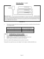
GAS CONVERSION
The gas control valve supplied on this heater is field convertible.
CAUTION: A qualified installer or service agency must perform any conversion of this gas control valve.
CONVERSION INSTRUCTIONS
1. Remove the converting seal cap. See Figure A. WARNING: Do not remove or tamper with any other
valve components.
2. Remove the black rubber gasket from the down side of the converting seal cap and reinstall gasket on
opposite side of converting seal cap. Gasket must be on down (valve) side of converting seal cap. See
Figure A.
3. Invert the converting seal cap and reinstall.
4. Insure that the desired gas (LP for liquefied petroleum or NAT for natural gas) symbol is visible after
reassembly of cap. See Figure A.
5. Remove the burner orifice and replace with burner orifice of correct size for your type of gas and elevation.
See orifice chart in these instructions.
6. Check for gas leaks.
7. Using a manometer, check for correct manifold pressure. 3.5” w.c. for natural gas and 10.0” w.c. for L.P.
NAT on top for Natural Gas
LP on top for LP Gas
NAT
LP
Converting Seal Cap
Gasket
Maxitrol Gas Valve
FIGURE A
Page 12
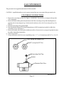
PROPER BURNER FLAME
BURNER BOX
COVER
The burner flame may be observed through the sight glass
located in the burner box cover. See Figure 11. A proper
flame will have a dark blue inner mantle, with a lighter blue
outer mantle that extends from the burner into the heat
exchanger tube, (see Figure 12). There is no primary air
adjustment on the burner, and proper flame is assured since
the correct manifold pressure and orificing has been done
at the factory for elevations up to 2,000 feet.
TO REMOVE MAIN BURNER FOR
INSPECTION AND CLEANING
a.
b.
c.
d.
e.
f.
g.
h.
Turn off all electrical supply to heater.
Turn off gas supply.
Remove cabinet cover.
Remove burner box cover. See Figure 13.
Remove two (2) screws holding burner to burner
bracket. See Figure 13.
Burner can now be slid forward off orifice, lift
up, slide back and out of burner box.
Clean or replace as needed.
Reinstall by reversing Steps “f” through “a”.
BURNER ORIFICE
SIGHT
GLASS
FIGURE 11
COMBUSTION
TUBE
BURNER
BURNER FLAME
This heater is orificed at the factory for elevations up to
2,000 ft. If installed above 2,000 ft., the BTU input must
be reduced 4% per 1,000 ft. See the following orifice chart
for the proper orifice for a specific elevation.
FIGURE 12
SPECIFIC ELEVATIONS
MODEL
NO.
0 to
2,000’
2,000’
4,000’
BBT53
BBT103
56
57
1.45mm 5 4
4,000’
6,000’
6,000’
8,000’
8,000’ 10,000’
59
55
60
55
72
66
73
68
Burner Box
NATURAL GAS
57
54
Burner Orifice
Burner
L.P. GAS
BBT54
BBT104
70
63
71
65
71
65
Burner Access
Plate
ORDER KIT #49800 44-1 HIGH ALTITUDE KIT FOR NAT. OR L.P.
GAS.
Burner
Bracket
Sight Glass
Gasket
FIGURE 13
Page 13
Sight
Glass
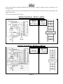
WIRING
If any of the original wire supplied with heater has to be replaced, it must be replaced with type 105 Degree C wire
or its equivalent.
CAUTION: Label all wires prior to disconnection when servicing controls. Wiring errors can cause improper and
dangerous operation.
Verify proper operation after servicing.
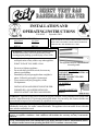
WIRING DIAGRAM - BBT53 & BBT54
BLACK
WHITE
PSV
V1
BLACK
BLACK
DRAFT
INDUCER
L2
RED
L2
BLUE
V2
GAS
VALVE
L1
IND
PURPLE
WHITE
LIMIT
SWITCH
WHITE
IGNITOR
TH
24 VAC
GND
GREEN
IGNITION MODULE
PRESSURE
SWITCH
BBT53,
BBT54
PICTORIAL
BBT53,
BBT54
LADDER
GAS VALVE
IGNITOR
DRAFT INDUCER
PRESSURE
SWITCH
115 VAC
IGNITION MODULE
24 VAC
GREEN
BLACK
ELECTRIC
POWER
SUPPLY
LIMIT SWITCH
THERMOSTAT
THERMOSTAT
WIRING DIAGRAM - BBT103 & BBT104
BLACK
WHITE
PSV
V1
BLACK
BLACK
DRAFT
INDUCER
L2
RED
L2
BLUE
V2
L1
GAS VALVE
LIMIT
SWITCH
LIMIT
SWITCH WHITE
IGNITOR
WHITE
IND
PURPLE
TH
24 VAC
GREEN
GND
IGNITION MODULE
PRESSURE
SWITCH
BBT103,
BBT104
PICTORIAL
GAS VALVE
IGNITOR
DRAFT
INDUCER
PRESSURE
SWITCH
115 VAC
IGNITION MODULE
24 VAC
BLACK
LIMIT SWITCH
GREEN
ELECTRIC
POWER
SUPPLY
BBT103,
BBT104
LADDER
LIMIT SWITCH
THERMOSTAT
THERMOSTAT
Page 14
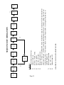
Thermostat
calls for heat
â
â
Spark Ignition
Energized
â
Gas control
valve opens gas
flow to burner
â
NO
Ignition
Proved
15 Sec.
â
Heating
Cycle
â
SEQUENCE OF OPERATION
Thermostat
satisfied
â
Gas control
valve closes
â
Draft
inducer off
20 Sec.
Post Purge
â
HEATER IS NOW IN STANDBY MODE.
STEP #
1)
Thermostat calls for heat.
2)
Inducer turns on.
3)
Pressure switch closes.
4)
Power to ignitor.
5)
Gas flow to burner.
6)
Burner ignition proven.
NOTE: If there is a malfunction in any of the above steps, the sequence will stop at that point
and return to Step 2. If after 3 attempts malfunction still occurs, control will go into lockout
mode for one hour. This one hour lockout can be bypassed by resetting the thermostat, or
interrupting power.
7)
Thermostat satisfied.
8)
Gas valve closes.
9)
Inducer turns off.
Lockout
after 3
attempts
Pressure
Switch Closes
(Fan Proved)
â
â
NO
Power to Draft
Inducer
(Ventor Motor)
â
Page 15
Stand-by
mode
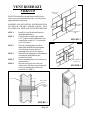
VENT RISER KIT
VRK5/10
MOUNTING
PLATE
NOTE: This kit has been designed and certified for use
with a Cozy gas baseboard heater only. Use only factory
supplied kit and components.
WARNING: DO NOT INSTALL IN WINDOW WELL
OR BELOW GRADE WHERE WATER MAY
ACCUMULATE. MUST NOT TOUCH THE GROUND!
STEP 1.
STEP 2.
STEP 3.
STEP 4.
STEP 5.
STEP 6.
WALL
Install Cozy gas baseboard heater per
installation instructions.
Check that the air intake pipe extends
1-1/2” past the outside wall and the vent
exhaust tube extends 2-1/2” past outside
wall. See Figure 1.
Place the mounting plate over the air
intake tube and slide back flush against
wall. Mark the location of the six
mounting holes on wall. See Figure 2.
Drill the six mounting holes. Depending on
wall material, install anchors (not
provided) if needed.
Secure mounting plate to wall with screws
(not provided).
Place the vent riser kit over the vent
exhaust tube, slide back into position and
secure to mounting plate with screws
provided. See Figure 3.
1-1/2”
AIR INTAKE
TUBE
VENT
EXHAUST
TUBE
2-1/2”
FIGURE 1
Page 16
AIR
INTAKE
TUBE
MOUNTING
HOLES
VENT EXHAUST
TUBE
FIGURE 2
VENT RISER KIT
INSTALLED
FIGURE 3
SIDE VALVE CONCEALER KIT - SVCK5/10
NOTE: This kit has been designed and certified for use with a Cozy gas baseboard heater only. Use only factory
supplied kit and components.
STEP 1.
STEP 2.
STEP 3.
STEP 4.
STEP 5.
With the offset up and out from the wall, place the mounting bracket flush to the right side of the
heater cabinet. Align the top of the mounting plate with the top of heater cabinet. Mark the
location of the mounting holes. See Figure 1.
Drill holes where marked. Depending on wall material, install wall anchors (nor provided) if
needed.
Secure mounting plate to wall with screws (not provided).
Attach the cover to the mounting plate by placing the cover top edge over the offset on the
mounting plate. Push the cover in toward wall until catch snaps into place. See Figure 2.
For access to the manual gas shut off valve, locate finger handle at the bottom of the cover. Pull
out until snap catch releases then lift cover up to remove from mounting plate. See Figure 2.
Offset must be out
from wall
COZY Gas
Baseboard
Heater
Mounting
Holes (4)
Mounting
Plate
Manual gas shut
off valve
FIGURE 1
Cover
COZY Gas
Baseboard
Heater
Cabinet
catch
Manual gas
shut off valve
Finger
handle
FIGURE 2
Page 17
BOTTOM VALVE CONCEALER KIT - BVCK5/10
NOTE: This kit has been designed and certified for use with a Cozy gas baseboard heater only. Use only factory
supplied kit and components.
STEP 1.
Place the mounting plate against the wall and flush with the bottom of the gas baseboard heater.
The mounting plate must cover the manual gas shut off valve. See Figure 1. Mark the location of
the mounting holes.
STEP 2.
Drill holes where marked. Depending on wall material, install anchors (not provided) if needed.
STEP 3.
Secure mounting plate to wall with screws (not provided).
STEP 4.
Attach the cover to the mounting plate by lining up the two catches inside the cover with catches
on mounting plate. Push cover toward wall until catches snap into place. See Figure 2.
STEP 5.
For access to the manual gas shut-off valve, grasp the cover on both sides and pull out until the
snap catches release.
COZY Gas
Baseboard
Heater
Manual gas shut
off valve must have
cut off above floor
Mounting Plate
Mounting plate
catches
4-1/4” Above floor
Mounting
Holes (4)
Floor
FIGURE 1
COZY Gas
Baseboard
Heater
Manual gas shut
off valve must have
cut off above floor
Wrapper
Wrapper catches
4-1/4” Above floor
Floor
FIGURE 2
Page 18
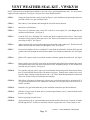
VENT WEATHER SEAL KIT - VWSK5/10
NOTE: This kit has been designed and certified for use with a Cozy gas baseboard heater only. Use only factory
supplied kit and components. See Figure 1 for parts list of Vent Weather Seal Kit.
STEP 1.
Change the location for the vent by following Figure 1 in the installation and operating instructions
provided with the Cozy gas baseboard heater.
STEP 2.
Drill a three (3) inch diameter hole through the wall of the chosen location.
STEP 3.
Measure the wall thickness.
STEP 4.
Using a two (2) inch tube cutter, cut the PVC wall sleeve seven-eights (7/8”) inch longer than the
measured wall thickness. See Figure 2.
STEP 5.
Clean the PVC sleeve and apply PVC cement (provided) on opposite sides of sleeve. Place straps
on cement leaving eight (8) inches past sleeve end. Wait ten (10) minutes for cement to dry before
proceeding to Step 6. See Figure 2.
STEP 6.
Apply petroleum jelly or an equivalent lubricant to the outside of the weather seal. The lubricant will
make it easier to push the weather seal through the wall. See Figure 2.
STEP 7.
From inside, hold the wall sleeve with the PVC straps lined up horizontally. Push the PVC pipe and
weather seal slowly through the wall until the weather seal is completely outside the wall. See Figure
3.
STEP 8.
Pull the PVC straps toward you to pull the weather seal firmly against the outside wall. See Figure
3.
STEP 9.
Being careful to keep the PVC straps lined up horizontally and pulled tight to maintain the outside
seal, bend the straps away from sleeve and secure to wall. Depending on type of wall, anchors (not
provided) may be required. See Figure 4.
STEP 10.
First, put blue pipe plug in PVC pipe to prevent insulation from getting inside! Insert nozzle from a
tube of foam insulation between the wall and the wall sleeve. Starting at the weather seal, slowly
inject the foam, working towards the inside wall. CAUTION: Read the manufacturers instructions
on the can of foam for special instructions and warnings.
STEP 11.
Wait fifteen (15) minutes for foam to dry, cut away any excess from around sleeve on inside wall. If
Cozy gas baseboard heater will be installed at a later date, leave the pipe plug in the wall sleeve to
seal the vent hole.
STEP 12.
Install the Cozy gas baseboard heater per the installation instructions provided with heater.
STEP 13.
Slide the O-ring over the air intake tube to a position approximately two (2”) inches from the end of
the tube. See Figure 5.
STEP 14.
Remove pipe plug from wall sleeve.
STEP 15.
Apply petroleum jelly or equivalent lubricant around the outside of the O-ring. Insert the air intake
tube through the PVC wall sleeve until back of heater is against the wall. Secure heater to wall.
CONT’D. --- ILLUSTRATIONS - NEXT PAGE
Page 19
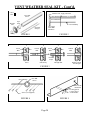
VENT WEATHER SEAL KIT - Cont’d.
Can of
Glue
Weather Seal - Apply Lubricant
PVC Wall
Sleeve
8”
Wall Thickness
PVC Wall Sleeve
Weather
Seal
Pipe
Plug
PVC Pull Strap
7/8” Longer
Than Wall
Thickness
PVC Pull
Strap (2)
O-Ring
FIGURE 2
FIGURE 1
1
2
Inside
Wall
4
3
Inside
Wall
Outside
Wall
Outside
Wall
PVC Pull
Straps
Insert
Push Slowly
Through Wall
Pull PVC Straps
To Pull Tight
FIGURE 3
PVC Pull Strap
PVC Wall
Sleeve
Back Of Gas
Baseboard
Screws (not supplied)
2”
FIGURE 4
FIGURE 5
Page 20
“O” Ring placed
2” from edge of
air intake tube
TROUBLE SHOOTING CHART
SYMPTOM
POSSIBLE CAUSES
Flame too large
1. Defective operator section of valve.
2. Burner orifice too large.
Yellow burner flame
CORRECTIVE ACTION
3. If installed above 2,000 ft.
1. Clogged burner ports.
2. Obstruction around vent cap.
Gas odor
Delayed Ignition
1. Gas leak.
1. Low gas pressure.
2. Igniter not properly located.
Failure to ignite
1. Main gas off.
2. Thermostat not set high enough to call
for heat.
3. Clogged burner orifice.
4. Incorrect wiring.
5. Defective valve.
6. No power to unit.
7. Defective pressure switch.
1. Defective or damaged thermostat wire,
or thermostat.
Burner won’t turn off
2. Thermostat location.
Incorrect gas input
Not enough heat
Too much heat
Main burner goes out
during normal operation
3.
4.
5.
1.
2.
Defective or sticking valve.
Excessive gas pressure.
Defective or damaged thermostat.
Gas input not checked.
Clogged orifice.
1. Furnace undersized.
2.
3.
1.
2.
1.
2.
3.
Temperature dial set too low.
Incorrect supply pressure.
Temperature dial set too high.
Combination control valve stuck open.
Defective flame sensor.
Input too high.
Cover around pilot lighter hole not air
tight.
4. Vent tubes not properly installed or
sealed.
5. Limit switch opens.
6. Exhaust or air intake tubes blocked.
Page 21
1. Replace valve.
2. Check with local gas company for proper
orifice size and replace.
3. See burne orifice section, Page 12.
1. Remove burners and check for
obstructions in throats, ports, and
orifices. Clean - but do not enlarge ports
or orifices.
2. Make sure area around vent cap is clear,
be sure vent system is sealed.
1. See Page 1.
1. Check gas supply pressure.
2. Check ignitor location and correct if
necessary.
1. Open all manual gas valves.
2. Set thermostat to higher temperature.
3. Clean burner orifice (do not enlarge).
4. Check wiring diagram.
5. Replace valve.
6. Check power supply.
7. Replace pressure switch.
1. Cean be checked by removing wire from
control board terminal. If burner goes off,
replace thermostat.
2. Re-locate thermostat out of drafts, hot, or
cold spots.
3. Replace valve.
4. Contact utility supplying gas.
5. Replace thermostat.
1. Re-check gas input.
2. Clean orifices with a smooth wood
toothpick, do not enlarge.
1. This is especially true when a dwelling
or room is enlarged. Have the heat loss
calculated and compare to furnace
output. Your gas company can supply
you with this information. If furnace is
undersized, replace with correct size unit,
or add up to two more heaters.
2. Raise temperature setting.
3. Check supply pressure.
1. Lower temperature setting.
2. Replace combination control valve.
1. Check voltage and replace if low.
2. Check input rate.
3. Tighten screws securing sight glass.
Check and replace gasket if needed.
4. Follow instructions. Check both
exhaust and air intake tubes, and vent
cap. Be sure all gaskets are in place and
properly sealed. Use only tubes and
vent cap supplied. Do not alter vent
tubes or cap. Check wall thickness and
tube lengths.
5. Check rate - remove any obstructions to
circulating air.
6. Remove obstruction. Check for snow.
TROUBLE SHOOTING CONTROL BOARD
TO IMPROVE DIAGNOSING AND SERVICING, THIS CONTROL MODULE IS EQUIPPED WITH A
SELF-DIAGNOSING RED INDICATOR LIGHT. TO INDICATE STAND-BY MODE AND PROPER
OPERATION, THIS LIGHT WILL REMAIN OFF. IF THERE SHOULD BE A MALFUNCTION, THE
LIGHT WILL FLASH A VARYING NUMBER OF TRIES WITH A PAUSE BETWEEN EACH SERIES
OF FLASHES. THE NUMBER OF FLASHES WILL INDICATE WHICH CIRCUIT TO CHECK.
# OF
FLASHES
1
2
3
REASON FOR
INDICATION
Air flow fault
POSSIBLE CAUSES
a.) Pressure switch tubing disconnected
or damaged.
b.) Pressure switch tubing to wrong
connections.
c.) Wire disconnected or damaged.
d.) Obstruction in vent pipe.
e.) Defective draft inducer.
Flame - no call a.) Defective gas valve.
for heat
b.) Defective control module.
c.) Defective thermostat wire.
Ignition Lock Out
a.) Defective ignitor.
(3 Attempts)
b.) Ignitor cable disconnected no gas to burner.
Heater is in one
hour lockout mode. c.) Manual gas control in OFF
This one hour
position.
lockout can be by- d.) Loose or damaged wire to gas
passed by resetting
valve.
the thermostat
MAINTENANCE INSTRUCTIONS
For correct and safe operation, keep heater and heater area clean.
At regular intervals, turn control valve to OFF, let heater cool and
clean inside control and heat exchanger compartments.
To clean outside cover, use a damp cloth, do not use any kind of
solvent of cleaning fluid as they may leave a residue that could
burn or give off odors when heater is turned on.
Have heater, including vent system, checked, cleaned and/or
repaired by a qualified service person prior to use each year.
Follow a regular service and maintenance schedule for safe and
efficient operation.
Do not obstruct combustion, ventilation or circulating air.
If any components are removed, make sure all gaskets are reinstalled
and are in good condition. If any sign of damage, replace gasket as
this is a sealed system and must be air-tight for proper operation.
DO NOT operate heater with any gasket missing or damaged. Failure
to replace a missing or damaged gasket may result in property
damage, personal injury or loss of life.
Page 22
CORRECTIVE ACTION
a.) Connect or replace tubing.
b.) Correct tubing connection.
c.) Replace or connect wire.
d.) Remove obstructions.
e.) Replace draft inducer.
a.) Replace gas valve.
b.) Replace control module.
c.) Check and replace thermostat wire.
a.) Replace ignitor.
b.) Connect ignition cable.
c.) Turn manual gas control to ON
position.
d.) Connect or replace wire to gas valve.
SERVICE RECORD
DATE
DATE
DATE
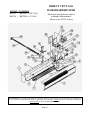
MODEL NUMBERS
BBT53 / BBT103 - NAT. GAS
BBT54 / BBT104 - L.P. GAS
DIRECT VENT GAS
BASEBOARD HEATER
Prices and specifications subject
to change without notice.
All prices are F.O.B. factory.
Mr. Contractor, we only sell parts through our wholesalers, but the prices listed are for your convenience. For prompt parts
service, contact the wholesaler from which you purchased your Cozy heater. NOTE: Parts prices & schematic drawings on
current models are shown at www.cozyheaters.com.
Page 23
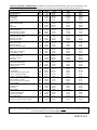
HOW TO PROPERLY ORDER PARTS: In addition to part description and part number, please give model number, serial
number, and type of gas used. This information can be found on the rating plate located inside the cabinet cover.
MODEL NUMBER
PART DESCRIPTION
End Cap, Left
End Cap, Right
Cabinet Base
Cabinet Cover
Heat Exchanger
Heat Exchanger Gasket
Igniter
Igniter Cable
Limit Switch
Limit Switch Bracket
Limit Switch Wire 27" White
Limit Switch Wire 26" White
Limit Switch Wire 46" White
Limit Switch Wire 17" White
Heat Exchanger Clamp
Burner Box / Air Drop
Sight Glass
Burner Access Plate
Sight Glass Gasket
Burner Access Plate Gasket
Burner Support Bracket
Burner
Burner Orifice, Natural Gas
Burner Orifice, L.P. Gas
Manifold
Gas Valve, Natural Gas
Gas Vlave, L.P. Gas
Draft Inducer
Draft Inducer Gasket
Draft Inducer Mounting Plate
Draft Inducer Outlet Gasket
Pressure Switch
Junction Box Cover
Junction Box
Control Module
Thermostat Wire Lead 6" Purple
(Pos. +) Gas Valve 8" Red
(Neg. -) Gas Valve 7" Dark Blue
Pressure Switch 8-1/2" White
Pressure Switch 11" Black
Power Cord Connector 5-1/2" Black
Ground 9" Green
Power Cord
Thermostat Wire
Thermostat
Air Box Gasket
Vent Exhaust Tube
Air Intake Tube Assembly
Air Intake Tube Gasket
Indoor Intake Gasket
Weather Seal
Flex Gas Line/Shut-off Valve Assembly
REF.
NO.
1
2
3
4
5
6
7
8
9
10
N/A
N/A
N/A
N/A
11
12
13
14
15
16
17
18
19
19
20
21
21
22
23
24
25
26
27
28
29
N/A
N/A
N/A
N/A
N/A
N/A
N/A
30
N/A
31
32
34
35
36
37
38
39
BBT53/BBT54
PART
LIST
NO.
PRICE
21045
$10.60
21040
$10.60
21055
$71.20
21030
$51.00
21175
$187.00
64151
$6.30
64009
$22.40
64210
$16.70
64086
$5.30
21125
$2.30
64200
$1.30
64202
$1.10
N/A
N/A
N/A
N/A
64011
$1.10
21065
$34.00
43252
$6.50
21115
$4.30
72067
$1.50
64150
$3.00
21130
$4.30
64005
$13.30
95315
$3.40
64251
$3.40
64008
$17.90
64105
$84.80
64106
$84.80
64075
$134.40
64152
$2.90
21140
$21.30
64154
$1.60
64065
$22.40
64053
$2.00
78059
$4.20
64007
$174.30
64215
$1.10
64216
$1.60
64217
$1.40
64218
$1.10
64219
$1.30
64220
$1.10
64221
$1.10
80202
$4.20
74518
$1.30
78355
$20.00
64153
$9.60
64015
$68.00
21150
$42.50
64020
$1.20
64155
$1.70
64405
$10.70
64072
$24.60
BBT103/BBT104
PART
NO.
21045
21040
21555
21530
21675
64151
64009
64210
64085*
21125*
64200
N/A
64198
64199
64011
21065
43252
21115
72067
64150
21130
64004
64252
64253
64008
64105
64106
64075
64152
21140
64154
64065
64053
78059
64007
64215
64216
64217
64218
64219
64220
64221
64205
74518
78355
64153
64015
21150
64020
64155
64405
64072
LIST
PRICE
$10.60
$10.60
$96.70
$72.30
$196.00
$6.30
$22.40
$16.70
$5.30
$2.30
$1.30
N/A
$1.80
$1.10
$1.10
$34.00
$6.50
$4.30
$1.50
$3.00
$4.30
$10.40
$3.40
$3.40
$17.90
$84.80
$84.80
$134.40
$2.90
$21.30
$1.60
$22.40
$2.00
$4.20
$174.30
$1.10
$1.60
$1.40
$1.10
$1.30
$1.10
$1.10
$5.60
$1.30
$20.00
$9.60
$68.00
$42.50
$1.20
$1.70
$10.70
$24.60
*USES 2
Mr. Contractor, we only sell parts through our wholesalers, but the prices listed above are for your convenience. For prompt
parts service, contact the wholesaler from which you purchased your Cozy heater. NOTE: Parts prices & schematic drawings
on current models are shown at www.cozyheaters.com.
Page 24
MARCH 2005
IMPORTANT SAFETY BULLETIN ON YOUR GAS CONTROL AND PILOT LIGHT
SYSTEM FOR HEATING EQUIPMENT
WHAT YOU DON’T KNOW CAN HURT YOU.
Your pilot light system has been designed for safe and reliable operation. Although safety mechanisms are built-in, the
potential for hazard exists. This information is intended to help you avoid these hazards.
YOUR GAS CONTROL AND PILOT LIGHT
SYSTEM
Your gas control and pilot light system has a safety
device whose purpose is to shut-off the gas supply
to the appliance if the pilot light goes out. If you
have trouble lighting the pilot or keeping it lit, it
may mean that this safety device is warning you
that there is a problem with your system.
Inspection and repairs or replacement must be
made by a trained gas service technician.
WHAT TO DO IF YOU SMELL GAS . . .
• Do not try to light any appliance.
• Do not touch any electrical switch; do not use any
phone in your building.
• Immediately call your gas supplier from a
neighbor’s phone. Follow the gas supplier’s
instructions.
• If you cannot reach your gas supplier, call the fire
department.
Installation and service must be performed by a
qualified installer, service agency or the gas supplier.
Do not store or use gasoline or other flammable vapors
and liquids in the vicinity of this or any other appliance.
TAMPERING IS DANGEROUS
The pilot safety system may also not work if you CRITICAL SAFETY POINTS TO REMEMBER . . .
do not follow the lighting instructions carefully • Your gas has been odorized so that you can smell
or if you tamper with the gas control that you use
it. Always smell around for gas before lighting your
to light the pilot. Tampering with the gas control,
appliance.
particularly with tools, can damage the safety • Sniff for L.P.-gas at floor level. LP-gas is heavier
than air and may temporarily exist at floor level.
mechanism in the control and can allow gas to
leak. This can result in a fire or explosion causing
property damage, personal injury or death.
IF YOU SMELL GAS, DON’T LIGHT IT
•
IF YOU CAN’T LIGHT IT,
DON’T FIGHT IT!
•
If you smell gas, do not attempt to light the pilot.
Do not cause a spark by turning on or off electrical
switches or appliances or by using the phone. Turn
off the gas to the appliances and call your gas
supplier from another location.
If your gas control has gotten wet as the result of
flooding or other wetting, it must be replaced
immediately by a trained gas service technician.
Water can lead to damage of the internal safety
mechanism in the gas control and can create a
hazardous condition.
THIS IS NOT AN ADVERTISEMENT
Page 25
LIMITED WARRANTY
The Louisville Tin & Stove Co. warrants to the
original user the accompanying product for the period
specified herein, provided said product is installed,
operated, maintained, serviced, and used according to the
instructions and specifications accompanying the product.
AS OUTLINED IN OUR INSTRUCTIONS, ANY
WARRANTY
CONSIDERATIONS
ARE
CONTINGENT ON INSTALLATION BY A
QUALIFIED INSTALLER (CONTRACTOR). SELFINSTALLATION IS NOT RECOMMENDED AND
MY INVALIDATE YOUR WARRANTY.
If within a period of one year from the date of
installation of the product, any part supplied by the
manufacturer proves to be defective due to workmanship
or material, it will replace such part, provided parts have
not been subjected to misuse, alteration, neglect, or
accidents. The term of the warranty for the heat exchanger
is covered in Table A below. Any claim not made within
ten (10) days after the expiration of the warranty period
shall be deemed waived by the user.
The manufacturer shall have no liability or be
required to perform any obligation under this warranty
unless, when requested, the user returns, at the user’s
expense, the component or product claimed defective, to
the manufacturer for inspection, to enable the manufacturer
to determine if the claimed defect is covered by this
warranty.
No charges for freight, labor or other expenses
incurred in the repair, removal, or replacement of any
product or component claimed to be defective, will be paid
by the manufacturer to the user, and the manufacturer will
not be liable for any expenses incurred, by the user, in
remedying any defect in the product.
Service under this warranty is the responsibility
of the installer. In the event service under this warranty is
needed, the user of the product shall request such service
directly from the installer. If the user is unable to locate
the installer, the user should write directly to the
manufacturer, and the name of an alternative service source
will be supplied.
The product safety registration card (packed
inside the appliance) must be completed and returned to
the factory.
THIS WARRANTY IS EXPRESSLY IN LIEU
OF ANY OTHER WARRANTIES, EXPRESS OR
IMPLIED (WHETHER WRITTEN OR ORAL). ANY
IMPLIED WARRANTY OF MERCHANTABILITY OR
OF FITNESS FOR A PARTICULAR PURPOSE IS
EXPRESSLY LIMITED TO THE DURATION OF THE
MANUFACTURER’S
EXPRESS,
WRITTEN
WARRANTY.
UNDER NO CIRCUMSTANCES SHALL THE
MANUFACTURER BE LIABLE FOR ANY SPECIAL,
INDIRECT OR CONSEQUENTIAL DAMANGES OR
EXPENSES ARISING DIRECTLY OR INDIRECTLY
FROM ANY COMPONENT OR FROM THE USE
THEREOF. THE REMEDIES SET FORTH HEREIN
SHALL BE THE EXCLUSIVE REMEDIES AVAILABLE
TO THE USER AND ARE IN LIEU OF ALL OTHER
REMEDIES.
SOME STATES DO NOT ALLOW
LIMITATIONS ON HOW LONG AN IMPLIED
WARRANTY LASTS, SO THE ABOVE LIMITATIONS
MAY NOT APLY TO YOU.
SOME STATES DO NOT ALLOW THE
EXCLUSION OR LIMITATION OF INCIDENTAL OR
CONSEQUENTIAL DAMAGES, SO THE ABOVE
LIMITATIONS OR EXCLUSIONS MAY NOT APPLY TO
YOU.
THIS WARRANTY GIVES YOU SPECIFIC
LEGAL RIGHTS, AND YOU MAY ALSO HAVE OTHER
RIGHTS, WHICH VARY, FROM STATE TO STATE.
TABLE A
Warranty for gas appliance heat exchangers only.
Product
Warranty Period
Cozy Gas Fired Floor Furnace
10 Years
Cozy Gas Fired Wall Furnace
10 Years
Cozy Gas Fired Vented Console Heater
10 Years
Cozy Gas Fired Direct Vent Heater
10 Years
Cozy Gas Fired Counterflow Furnace
10 Years
Cozy Gas Fired Counterflow Direct Vent Furnace
10 Years
Cozy Gas Fired Mobile Home Direct Vent Furnace
10 Years
Cozy Gas Fired Hi-Efficient Direct Vent Wall Furnace
10 Years
Cozy Gas Fired Direct Vent Baseboard Heater
10 Years
LOUISVILLE TIN AND STOVE COMPANY
P.O. Box 2767 - Louisville, Kentucky 40201-2767