1
iDP3221 User’s Manual
Declaration of Conformity
Manufacturer’s Name :
Manufacturer’s Address
Declare the Product
Product Name
Model Number(s)
: Japan CBM Corporation
: CBM Bldg., 5-68-10, Nakano, Nakano-ku
Tokyo, 164-0001, Japan
Line Thermal Printer
iDP3221 Series
(iDP3221RF, iDP3221PF)
(S.No.9990001 ~ )
Conform to the following Standards
LVD
EMC
: EN60950
: EN55022
: EN61000-3-2
: EN61000-3-3
: EN55024
: EN61000-4-2
: EN61000-4-3
: EN61000-4-4
: EN61000-4-5
: EN61000-4-6
: EN61000-4-8
: EN61000-4-11
: A11: 1997
: 1998 Class A
: 1995
: 1995
: 1995
: 1995 ±4KV CD, ±8KV AD
: 1995 3V/m, 80MHz-1000MHz AM1KHz 80%
: 1995 ±1.0KV (AC mains), ±0.5KV (Signal Lines)
: 1995 ±1KV Normal mode, ±2KV Common mode
: 1996 3V, 0.15MHz-80MHz AM1KHz 80%
: 1993 50Hz, 3A/m (Out of scope)
: 1994 10 ms/95%, 500 ms/30%, 5000 ms/100%
Supplementary Information
“The product complies with the requirements of the Low Voltage Directive 73/23/EEC, 93/68/EEC and
the EMC Directive 89/336EEC, 92/31/EEC, 93/68EEC”
Place
Tokyo, Japan
Date
August.1999
Signature
Full Name :
Position :
Mikio Moriya
General Manager
R & D Department
Europe Contact :
Norco Declaration AB
Box 7146 S-250 07 Helsingborg Sweden
Warning
This is a Class A products.
In a domestic environment this product may cause radio interference in which
case the user may be required to take adequate measures.
This declaration is applied only for 230V model.
CITIZEN
iDP3221 User’s Manual
IMPORTANT SAFETY INSTRUCTIONS
•
•
•
•
•
•
•
•
•
•
•
•
•
Read all of these instructions and save them for future reference.
Follow all warnings and instructions marked on the product.
Unplug this product from the wall outlet before cleaning. Do not use liquid or aerosol cleaners. Use
a damp cloth for cleaning.
Do not use this product near water.
Do not place this product on an unstable cart, stand or table. The product may fall, causing serious
damage to the product.
Slots and openings on the back or bottom of the case are provided for ventilation. To ensure reliable
operation of the product and to protect it from overheating, do not block or cover these openings. The
openings should never be blocked by placing the product on a bed, sofa, rug of other similar surface.
This product should never be placed near or over a radiator or heater. This product should not be
placed in an built-in installation unless proper ventilation is provided.
This product should be operated from the type of power source indicated on the marking label. If you
re not sure of the type of power available, consult your dealer or local power company.
Do not allow anything to rest on the power cord. Do not place this product where the cord will be
walked on.
If an extension cord is used with this product, make sure that the total of the ampere ratings of the
products plugged into the extension cord does not exceed the extension cord ampere rating. Also,
make sure that the total of all products plugged into the wall outlet does not exceed 15 amperes.
Never push objects of any kind into this product through cabinet slots as they may touch dangerous
voltage points or short out parts that could result in a risk of fire or electric shock. Never spill liquid
of any kind on the product.
Except as explained elsewhere in this manual, do not attempt to service this product by yourself.
Opening and removing the covers that are marked “Do Not Remove” may expose you to dangerous
voltage points or other risks. Refer all servicing on those compartments to service personnel.
Unplug this product from the wall outlet and refer servicing to qualified service personnel under the
following conditions:
A. When the power cord or plug is damaged or frayed.
B. If liquid has been spilled into the product.
C. If the product has been exposed to rain or water.
D. If the product does not operate normally when the operating instructions are followed. Adjust only
those controls that are covered be the operating instructions since improper adjustment of other
controls may result in damage and will often require extensive work by a qualified technician to
restore the product to normal operation.
E. If the product has been dropped or the cabinet has been damaged.
F. If the product exhibits a distinct change in performance, indicating a need for service.
Please keep the poly bag which this equipment is packed in away from children or throw it away to
prevent children from putting it on. Putting it on may cause suffocation.
CITIZEN
iDP3221 User’s Manual
WICHTIGE SICHERHEITSANWEISUNGEN
•
•
•
•
•
•
•
•
•
•
•
Lesen Sie die nachfolgenden Anweisungen sorgfältig durch und bewahren Sie sie auf.
Befolgen Sie alle auf dem Drucker vermerkten Hinweise und Anweisungen. Vor dem Reinigen
grundsätzlich Stecker aus der Steckdose ziehen. Keine Flüssigkeiten oder Aerosolreiniger benutzen.
Nut mit einem feuchten Tuch abwischen.
Der Drucker darf nicht in der Nähe von Wasser aufgestellt werden.
Drucker nicht auf einem unstabilen Wagen, Stand oder Tisch aufstellen. Der Drucker könnte
herunterfallen und dabel beschädigt werden.
Schlitze und Öffnungen im Gehäuse, in der Rückwand und im Boden dienen der Belüftung. Sie
dürfen keinesfalls zugedeckt oder blockiert werden, da sich der Drucker sonst überhitzt. Drucker
nicht auf ein Bett, Sofa, Teppich oder dergleichen stellen. Drucker nicht in der Nähe eines
Heizkörpers aufstellen. Drucker darf nicht eingebaut werden, falls nicht für ausreichende Belüftung
gesorgt ist.
Drucker nur mit der auf dem Typschild angegebenen Spannung betreiben. Wenn Sie sich nicht sicher
sind, fragen Sie ihren Händler oder ihr zuständiges Elektrizitätswerk.
Nichts auf das Stromanschlußkabel stellen. Kabel muß so verlegt werden, daß man nicht darauftreten
kann.
Ein etwaiges Verlängerungskabel muß der Stromstärke aller daran angeschlossenen Geräte entsprechen.
Keine Gegenstände in die Gehäuseschlitze schieben.
Drucker darf nur da gewartet werden, wo im Handbuch angegeben, Öffnen und. Abnehmen von
Abdeckungen, die mit “Do not remove” gekennzeichenet sind, könnte gefährliche spannungführende
Stellen oder sonstige Gefahrenpunkte freilegen. Die Wartung solcher Stellen darf grundsätzlich nur
von besonders ausgebildetem Fachpersonal vorgenommen werden.
A. Wenn das Stromanschlußkabel oder der Stecker beschädigt oder durch-gescheuert ist.
B. Wenn Flüssigkeit auf dem Drucker verschüttet wurde.
C. Wenn der Drucker im Regen gestanden hat oder Wasser darauf verschüttet wurde.
D. Wenn der Drucker trotz genauer Befolgung der Betriebsvorschriften nicht richtig arbeitet. Nur die
in der Bedienungsanleitung angegebenen Einstellungen vornehmen. Ein Verstellen anderer
Bedienungselemente könnte den Drucker beschädigen und macht umständliche Arbeiten eines
qualifizierten Technikers erforderlich, um den Drucker Wieder auf den normalen Betrieb
einzustellen.
E. Wenn der Drucker heruntergefallen ist oder das Gehäuse beschädigt wurde.
F. Wenn der Drucker in seiner Leistung nachläßt.
Bitte halten Sie den Kunststoffbeutel, in den die Ware verpackt ist, von Kindern entfernt, oder werfen
Sie ihn weg, damit er nicht in die Hande von Kindern gerät. Das Überstülpen des Beutels kann zum
Ersticken führen.
Lärmemission kleiner 70dBA
CITIZEN
iDP3221 User’s Manual
IMPORTANT: This equipment generates, uses, and can radiate radio frequency energy and if not
installed and used in accordance with the instruction manual, may cause interference to radio
communications.
It has been tested and found to comply with the limits for a Class A computing device
pursuant to Subpart J of Part 15 off FCC Rules, which are designed to provide reasonable protection against
such interference when operated in a commercial environment.
Operation of this equipment in a
residential area is likely to cause interference, in which case the user at his own expense will be required to
take whatever measures may be necessary to correct the interference.
CAUTION: Use shielded cable for this equipment.
Sicherheitshinweis
Die Steckdose zum Anschluß dieses Druckers muß nahe dem Grät angebracht und leicht zugänglich sein.
For Uses in Canada
This digital apparatus does not exceed the class A limits for radio noise emissions from digital, apparatus,
as set out in the radio interference regulations of the Canadian department of communications.
Pour L’utilisateurs Canadiens
Cet appareil numérique ne dépasse pas les limites de carégorie a pour les émissions de bruit radio émanant
d’appareils numériques, tel que prévu dans les réglements sur l’interférence radio du départment Canadien
des communications.
CITIZEN
iDP3221 User’s Manual
<CAUTIONS>
1. Prior to using the equipment, be sure to read this User's Manual thoroughly.
Please keep it handy for reference
whenever it may be needed.
2. The information contained herein may be changed without prior notice.
3. Reproduction of part or all of this User's Manual without permission is strictly prohibited.
4. Never service, disassemble, or repair parts that are not mentioned in this User's Manual.
5. Note that we will not be responsible for damages attributable to a user's incorrect operation/ handling or an
improper operating environment.
6. Operate the equipment only as described in this User's Manual; otherwise accidents or problems may result.
7. Data are basically temporary; they cannot be stored or saved permanently or for a long time.
Please note that
we will not be responsible for damages or losses of profit resulting from losses of the data attributable to
accidents, repairs, tests, and so on.
8. If you have any questions or notice any clerical errors or omissions regarding the information in this manual,
please contact our office.
9. Please note that, notwithstanding Item 8 above, we will not be responsible for any effects resulting from
operation of the equipment.
CITIZEN
iDP3221 User’s Manual
SAFETY PRECAUTIONS ----- BE SURE TO OBSERVE
In order to prevent hazards to an operator or other persons and damage to property, be sure to
observe the following precautions.
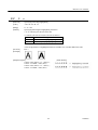
z
The following describes the degrees of hazard and damages that can occur if the given instructions are
neglected or the equipment is incorrectly operated.
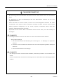
WARNING
Negligence of this precaution may result in death or serious injury.
CAUTION
Negligence of this precaution may result in injury or damage to property.
This is an illustration mark used to alert your attention.
This is an illustration mark used to indicate such information as an instruction or the like.
CITIZEN
iDP3221 User’s Manual
WARNING
z
•
•
•
•
•
•
•
•
•
•
•
•
•
z
Never handle the equipment in the following manners, as it may break, become out of order, or
overheat causing smoke and resulting in fire or electric shock.
If the equipment is used in an abnormal condition, such as when broken, then problems, smoke
emission, abnormal odor/noise, and fire can result. If an abnormal condition exists, be sure to turn off
the power, disconnect the power plug from a plug socket, and contact our dealer. Never repair the
equipment on your own - it is very dangerous.
Do not allow the equipment to receive a strong impact or shock, such as kicking, stomping, hitting,
dropping, and the like.
Install the equipment in a well-ventilated place. Do not use it in such a manner that its ventilation
port will be blocked.
Do not install the equipment in a place like a laboratory where chemical reactions are expected, or in a
place where salt or gases are contained in the air.
Do not connect/disconnect a power cord or a data cable, while holding the cable. Do not pull, install,
use, or carry the equipment in such a manner that force will be applied to the cables.
Do not drop or insert any foreign substances, such as clips or pins, into the equipment.
Do not spill any liquid or spray any chemical-containing liquid over the equipment. If any liquid is
spilled on it, turn off the power, disconnect the power cable and power cord from the plug socket, and
so on, and contact our dealer.
Do not disassemble or remodel the equipment. Negligence of this may cause fire or electric shock.
Should you drop or break this AC adapter by any chance, unplug it immediately and contact our office.
Using it in that condition may result in fire or electric shock.
Should water enter inside the equipment by any chance, unplug it and contact our office. Using it in
that condition may result in fire or electric shock.
Use the equipment only with the specified commercial power supply. Negligence of this may result
in fire, electric shock, or problems.
Do not damage, break, process, bend/pull by force, twist, or bundle an AC adapter cord. Also, do not
put a heavy substance on it or heat it. The AC adapter could be broken, resulting in fire, electric
shock, or trouble. If the AC adapter cord is damaged, contact our office.
Do not connect/disconnect the AC adapter with wet hands. It may result in electric shock or other
problems.
Do not overload a single electrical outlet, using a table tap or a current tap socket. It may result in fire
or electric shock.
An equipment packing bag must be discarded or kept away from children. A child can suffocate if the
bag is placed over the head.
CITIZEN
iDP3221 User’s Manual
PRECAUTIONS FOR INSTALLATION
•
•
•
•
•
•
•
•
•
•
•
•
•
•
•
•
•
Do not use or store the equipment in a place exposed to fire, moisture, or direct sunshine, or in a place
near a heater or thermal device where the prescribed operating temperature and humidity are not met, or
in a place exposed to much oil, iron powder, or dust. The equipment may become out of order, emit
smoke, or catch fire.
Do not install or use the equipment in a place like a laboratory where chemical reactions are expected,
or in a place where salt or gases are contained in the air. There is a danger of fire or electric shock.
Install the printer on a flat, stable desk or table that is free from vibration, in a well-ventilated place.
Do not place anything on the printer or leave small objects, like a clip or pin, around it. A foreign
object could cause trouble if it gets inside.
Do not use the equipment near a radio or TV receiver. Do not share the power from a plug socket a
radio or TV receiver is connected to. It may cause a reception problem.
Use the equipment only at the specified power supply, voltage and frequency. Otherwise, it may emit
smoke and catch fire or cause other problems.
Connect only the specified power source. Use of an unspecified power source could cause trouble or
smoke/fire.
Confirm that a plug socket used for connection has sufficient capacity.
Avoid connecting a power cable to a plug socket shared by other devices or extending the wiring too far.
It may result in the cable catching fire or a power outage. Also, do not step on or apply an excessive
force (Pull, load) to the cable, and do not use the printer with such a force applied to it.
Never connect a grounding cable (Frame ground) to a gas pipe. There is a danger of explosion.
When connecting or disconnecting the grounding cable, be sure to disconnect the power cable and the
power plug from the plug socket.
When connecting/disconnecting the cables, be sure to turn off the power first, including the connected
side, and then connect/disconnect them, holding a plug and a connector. Pulling the cable itself could
cause it to snap or become damaged.
Connect a power cable or a connector cable securely. If a reverse-polarity connection is made,
internal elements may be broken or a mating device may be adversely affected.
Use a shielding wire or twisted pair wire for a signal line, in order to minimize noise effect. Do not
route the cable too long or connect it to a noisy device. Connection to a noisy device could cause
erroneous printing due to corrupt data, and so on.
When a drawer kick connector is provided, do not connect any device other than the prescribed solenoid
specifications. Negligence of this could cause trouble.
Use the equipment in an environment where there is a plug socket near the main body and you can
easily disconnect the power plug from it, to shut off the power.
When the equipment will not be used for a long period of time, unplug it and remove the paper roll from
it.
When transporting the equipment, remove the paper roll from the paper holder.
CITIZEN
iDP3221 User’s Manual
PRECAUTIONS FOR HANDLING
Do not handle the equipment in the following manners, because problems may result.
•
Do not use any other power source besides the accessory AC adapter. Also, do not use the AC adapter
for other purposes.
• Do not print without paper.
• Do not drop or put any foreign object, such as a clip, pin, or the like, inside the printer.
• Do not spill any liquid or spray any chemical-containing liquid over the equipment.
• Do not stamp on, drop, hit, or give a strong shock to the equipment.
• Never use a pointed object, such as a pen, to operate the operation panel.
• Do not use Scotch tape to fasten paper together for continuous use. It could damage the printing head.
• Never pull the set paper forcibly.
To Prevent Injury and Spreading of Damage
•
•
•
•
•
Do not touch the printing part of the print head.
When turning on the power, do not touch the moving parts, such as a cutter and gear inside the main
body, or electric parts.
Be careful to avoid bodily injure or damaging other objects with an edge of sheet metal.
Should any error occur while operating the equipment, stop it immediately and disconnect the power
plug from the plug socket.
Should a problem occur, leave solving it to our serviceman. Do not disassemble the equipment on
your own.
CITIZEN
iDP3221 User’s Manual
DAILY MAINTENANCE
•
•
•
•
At the time of maintenance, be sure to turn off the power switch of the printer and unplug it from the
socket.
When cleaning the platen, wipe off dust or dirt from the platen with a cotton swab dipped in ethyl
alcohol.
Use a dry soft cloth to wipe off stains and dust from the surfaces of the main body case. For severe
soiling, dip the cloth in water and wring it, for wiping off the soil. Never use organic solvents, such as
alcohol, thinner, trichlene, benzene, ketone, or chemical dusters.
If the equipment is contaminated with paper powder, use a soft brush to clean it. Be careful not to
damage the printing head.
CAUTION: The printing head and motor are very hot.
Be careful not to touch them
immediately after printing.
z
Cleaning the Printing Head
1. Referring to "4.6 Removing Paper Jam," detach the platen roller unit.
2. Moisten gauze slightly with alcohol, and clean the heating surface of the printing head with it.
3. Reattach the platen roller unit.
CAUTION: The printing head and motor are very hot.
immediately after printing.
Be careful not to touch them
Do not touch the heating surface of the head with a bare
hand or metal.
CITIZEN
iDP3221 User’s Manual
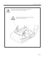
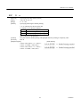
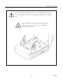
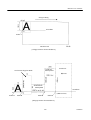
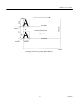
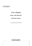
A caution label is stuck onto the following place. Carefully read
the cautions on operation to correctly use the printer.
This label warns that the head becomes hot in operation,
and touching it may result in burns.
CITIZEN
iDP3221 User’s Manual
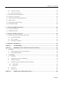
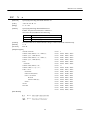
CONTENTS
1. OUTLINE ...............................................................................................................................................................1
1.1
Features....................................................................................................................................................................... 1
1.2
Unpacking................................................................................................................................................................... 1
2. BASIC SPECIFICATIONS ...................................................................................................................................3
2.1
Model Classifications ................................................................................................................................................. 3
2.2
Basic Specifications.................................................................................................................................................... 4
2.3
Paper Specifications.................................................................................................................................................... 5
2.3.1
Recommended Paper ......................................................................................................................................... 5
2.3.2
Printing Position ................................................................................................................................................ 5
2.3.3
Head and Paper Cutter Layout........................................................................................................................... 6
3. OUTER APPEARANCE AND COMPONENT PARTS.....................................................................................7
4. OPERATION ..........................................................................................................................................................8
4.1
Connecting AC Adapter ............................................................................................................................................. 8
4.2
Connecting Interface Cable ........................................................................................................................................ 9
4.3
Inserting the Paper ...................................................................................................................................................... 9
4.4
How to Remove Remaining Paper Roll.................................................................................................................... 10
4.4.1
Inserting the Paper ........................................................................................................................................... 10
4.4.2
Manually Inserting the Paper........................................................................................................................... 12
4.5
How to Remove Remaining Paper Roll.................................................................................................................... 13
4.6
Eliminating the Paper Jam ........................................................................................................................................ 14
4.7
Unlocking the Cutter................................................................................................................................................. 16
4.8
Clearing the Head ..................................................................................................................................................... 17
4.9
Operation Panel and Display of Error....................................................................................................................... 18
4.10 Hexadecimal Dumps................................................................................................................................................. 20
5. DIP SWITCH SETTING .....................................................................................................................................21
5.1
Location of DIP Switch ............................................................................................................................................ 21
5.2
DIP Switch Function................................................................................................................................................. 22
6. PARALLEL INTERFACE ..................................................................................................................................23
6.1
Bi-directional Parallel Interface (IEEE 1284)........................................................................................................... 23
6.1.1
Compatibility Mode......................................................................................................................................... 23
6.1.2
Reverse Mode .................................................................................................................................................. 23
CITIZEN
iDP3221 User’s Manual
6.1.3
6.2
6.3
Connector Pin Assignment .............................................................................................................................. 24
Parallel Interface (CENTRONICS) ...................................................................................................................... 25
6.2.1
Specifications................................................................................................................................................... 25
6.2.2
Connector's Pin Configuration......................................................................................................................... 25
Input and Output Signals....................................................................................................................................... 26
6.3.1
Input and Output Signals ................................................................................................................................. 26
6.3.2
Electrical Characteristics ................................................................................................................................. 27
6.3.3
Timing Chart.................................................................................................................................................... 28
6.3.4
Data Receiving Control ................................................................................................................................... 28
6.3.5
Buffering.......................................................................................................................................................... 28
7. SERIAL INTERFACE.........................................................................................................................................29
7.1
Specifications............................................................................................................................................................ 29
7.2
Connector's Pin Configuration.................................................................................................................................. 29
7.3
Input and Output Signals .......................................................................................................................................... 30
7.3.1
Input and Output Signals ................................................................................................................................. 30
7.3.2
Data Configuration .......................................................................................................................................... 31
7.3.3
Error Detection ................................................................................................................................................ 31
7.3.4
Data Receiving Control ................................................................................................................................... 32
7.3.5
Buffering.......................................................................................................................................................... 32
7.3.6
Electrical Characteristics ................................................................................................................................. 32
8. DRAWER KICK-OUT CONNECTOR, POWER CONNECTOR..................................................................33
8.1
8.2
Drawer Kick-Out Connector..................................................................................................................................... 33
8.1.1
Specifications of Drawer Kick-Out Connector ................................................................................................ 33
8.1.2
Connector's Pin Configuration......................................................................................................................... 33
Power Connector ...................................................................................................................................................... 34
9. MAINTENANCE AND SERVICE .....................................................................................................................35
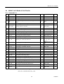
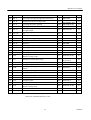
10. PRINT CONTROL FUNCTIONS......................................................................................................................36
10.1 Command List .......................................................................................................................................................... 36
10.2 Command Details ..................................................................................................................................................... 39
10.2.1 Descriptions of Each Item ............................................................................................................................... 39
10.2.2 Command Details ............................................................................................................................................ 40
CITIZEN
iDP3221 User’s Manual
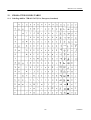
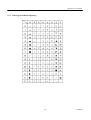
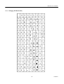
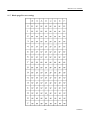
11. CHARACTER CODES TABLE .......................................................................................................................112
11.1 CodePage 00H to 7FH & PC437(USA, European, Standard) ................................................................................ 112
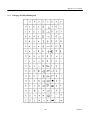
11.2 Code Page Katakana(Japanese) .............................................................................................................................. 113
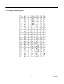
11.3 Codepage PC850(Multilingual) .............................................................................................................................. 114
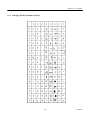
11.4 Codepage PC860(Portguese) .................................................................................................................................. 115
11.5 Codepage PC893(Canadian-French) ...................................................................................................................... 116
11.6 Codepage PC865(Nordic)....................................................................................................................................... 117
11.7 Blank page(For user setting)................................................................................................................................... 118
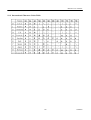
11.8 International Character Codes Table....................................................................................................................... 119
APPENDIX 1.
PAGE MODE...............................................................................................................................120
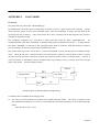
APPENDIX 2.
BI-DIRECTIONAL PARALLEL INTERFACE ......................................................................128
1.
Overview................................................................................................................................................................ 128
1.1
Parallel Interface Communication Modes .............................................................................................................. 128
1.2
Interfacing Phase .................................................................................................................................................... 129
2.
Negotiation ............................................................................................................................................................ 130
2.1
Overview ....................................................................................................................................................... 130
2.2
Negotiation Procedure ................................................................................................................................... 130
2.3
Precautions..................................................................................................................................................... 131
2.4
Data Communication from Printer to Host .................................................................................................... 132
2.4.1
Nibble Mode ............................................................................................................................................ 132
2.4.2
Byte Mode................................................................................................................................................ 132
2.5
Device ID....................................................................................................................................................... 134
2.6
Terminator ..................................................................................................................................................... 135
APPENDIX 3
IDENTIFICATION OF SEND STATUS...................................................................................136
APPENDIX 4.
BLOCK DIAGRAM ...................................................................................................................137
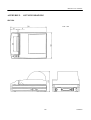
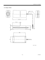
APPENDIX 5.
OUTLINE DRAWING................................................................................................................138
<<< German >>>
4. BETRIEB ............................................................................................................................................................148
4.1
Anschließen des Netzteils....................................................................................................................................... 148
4.2
Anschließen des Schnittstellenkabels ..................................................................................................................... 149
4.3
Anschluß des Schubladenausschubsteckers............................................................................................................ 149
4.4
Einlegen des Papiers ............................................................................................................................................... 150
CITIZEN
iDP3221 User’s Manual
4.4.1
Einlegen des Papiers ...................................................................................................................................... 150
4.4.2
Papier manuell einlegen................................................................................................................................. 152
4.5
Herausnehmen der Restpapierrolle ......................................................................................................................... 153
4.6
Beseitigen von Papierstau....................................................................................................................................... 154
4.7
Initialisierung des Schneidemechanismus .............................................................................................................. 156
4.8
Kopf reinigen ..................................................................................................................................................157
4.9
Bedienfeld und Fehleranzeigen .............................................................................................................................. 158
4.10 Hexadezimal-Dumps .............................................................................................................................................. 160
5. DIP-SCHALTEREINSTELLUNG ...................................................................................................................161
5.1
Lage der DIP-Schalter ............................................................................................................................................ 161
5.2
DIP-Schalterfunktion.............................................................................................................................................. 162
6. PARALLELSCHNITTSTELLE .......................................................................................................................163
6.1
Bidirektionale Parallelschnittstelle (IEEE 1284) .................................................................................................... 163
6.1.1
Kompatibilitätsmodus.................................................................................................................................... 163
6.1.2
Reverse-Modus .............................................................................................................................................. 163
6.1.3
Pinbelegung der Buchse ................................................................................................................................ 164
9. WARTUNG UND DIENST................................................................................................................................165
ANHANG 1.
SEITENMODUS .........................................................................................................................166
ANHANG 2.
BIDIREKTIONALE PARALLELSCHNITTSTELLE ...........................................................174
1.
2.
Übersicht................................................................................................................................................................ 174
1.1
Übertragungsmodi der Parallelschnittstelle ................................................................................................... 174
1.2
Kommunikationsphasen ................................................................................................................................ 175
Verhandlung .......................................................................................................................................................... 176
2.1
Übersicht........................................................................................................................................................ 176
2.2
Vorgehensweise bei der Verhandlung ............................................................................................................ 176
2.3
Besonders beachten ....................................................................................................................................... 177
2.4
Datenübertragung vom Drucker zum Host-Computer................................................................................... 179
2.4.1
Nibble Mode ............................................................................................................................................ 179
2.4.2
Byte Mode................................................................................................................................................ 180
2.5
Geräte-ID ....................................................................................................................................................... 181
2.6
Terminierung.................................................................................................................................................. 182
ANHANG 3.
ERMITTLUNG DES SENDESTATUS .....................................................................................184
CITIZEN
iDP3221 User’s Manual
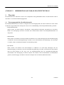
1.
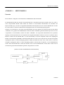
OUTLINE
This is a small line thermal printer developed to be used for various data communication terminals, POS
terminals, kitchen printer, and so on.
applications.
1.1
With its abundant features, it can be widely used for various types of
Prior to using the printer, read this manual thoroughly to understand its contents..
Features
1.
Small, lightweight, with a small footprint.
2.
Designed with a reduced number of components to ensure low cost.
3.
Paper is added by simply placing the paper and closing the cover.
4.
A removable platen mechanism simplifies maintenance (e.g. paper handling and head cleaning).
5.
Line thermal printing for high speed and low noise.
6.
A long-life head with a simple mechanism to ensure high reliability.
7.
Built-in input buffer.
8.
Bar code printing (with special commands).
9.
Built-in drawer kick-out interface.
10. Auto cutter fitted as standard.
11. User registration of external characters.
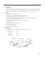
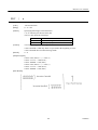
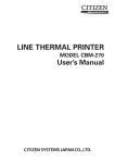
1.2
Unpacking
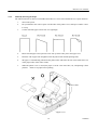
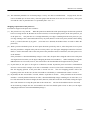
(1) When unpacking the printer, confirm that the following parts are provided.
• Printer body
----- 1 unit
• Sample paper roll
----- 1 roll
• AC adapter
----- 1 piece
• AC power cord
----- 1 piece
• User's manual
----- 1 copy
Printer Body
Sample Paper Roll
User's Manual
AC Adapter
AC Power Cord
1
CITIZEN
iDP3221 User’s Manual
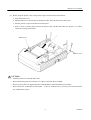
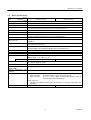
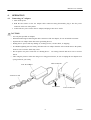
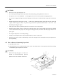
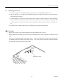
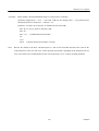
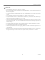
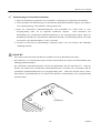
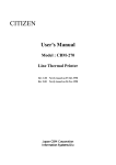
(2) Before using the printer, remove the protective paper for the head as shown below:
1. Open the printer cover.
2. Pull the platen levers at both sides of the platen roller unit in the direction of the arrows.
3. Pull the protective paper in the direction of the arrow.
4. Insert a sheet of printer paper between the platen roller and the head when the printer is to remain
unused for a long period of time.
Platen Lever
Printer Cover
CAUTION :
• Install the printer on a flat and stable desk.
• Do not install the printer near a heater or in a place exposed to direct sunlight.
• Do not use the printer in a high-temperature, high-humidity, and contaminated environment.
• Do not allow dew condensation on the printer.
If dew is condensed on it, leave the power turned off until
dew condensation is gone.
2
CITIZEN
iDP3221 User’s Manual
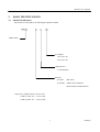
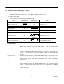
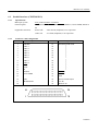
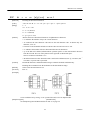
2.
BASIC SPECIFICATIONS
2.1
Model Classifications
The models are classified by the following designation method:
iDP3221
-
R
F
120
Model Name
AC Adapter
120: 120 V AC
230: 230 V AC
Characters Set
F: International
Interface
R: Serial
(RS-232C)
P: Parallel
(IEEE 1284 Compliant,
Bi-directional communication)
* Special AC Adapter and AC Power Cord
31AD-U (120V AC --- 3-core cord)
31AD-E (230V AC --- Class I cord)
3
CITIZEN
iDP3221 User’s Manual
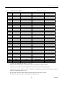
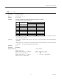
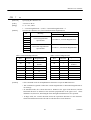
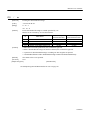
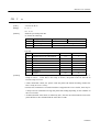
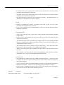
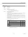
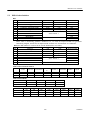
2.2
Basic Specifications
Model
Item
Printing system
Printing width
Dot density
Printing speed
Printing columns
Printing size
Line pitch
Character types
Bar code type
Paper
Interface
Input buffer
Supply DC voltage
Power consumption
AC adapter
Type
Weight
iDP3221–RF120
iDP3221–PF120
iDP3221–RF230
iDP3221–PF230
Line thermal dot printing
72.192 mm/512 dots
Width: 0.141 mm, Length: 180 DPI (0.141 mm)
63.45 mm/sec.
(At maximum speed, print density level 2), (450-dot line/sec.)
42 columns (Font A) , 56 columns (Font B)
1.41×3.39 mm (Font A) , 0.99×3.39 mm (Font B)
4.23 mm (1/6 inch)
Can be set with a command (See 10.2 "Command Details.")
Alphanumeric, international characters, extended graphic
UPC-A/E, JAN(EAN) 13-/18-column, ITF, CODE 39, CODE 128, CODABAR,
CODE 93
Thermal paper roll : 80 + 0/- 1 mm×φ83 (max.) mm
(See Paper Specifications)
Serial (RS-232C)
Parallel (IEEE 1284 compliant) (Bi-directional communication)
4 KB or 72 bytes (Selectable with the DIP switch)
24 V DC +/- 7%
100 W
Rated input : 100∼240 V AC, 50/60 Hz, 120 VA
Rated output : 24 V DC, 1.8 A
31AD-U
31AD-E
Main body: Approx. 1.3 Kg
AC adapter: Approx. 450 g
152 (W) × 201 (D) × 123 (H) mm
5 ∼ 40°C, 35 ∼ 85 % RH (No dew condensation)
Outer dimensions
Operating temperature
and humidity
Storage temperature and -20 ∼ 60°C, 10 ∼ 90% RH (No dew condensation)
humidity
Reliability
Printing head life:
Pulse resistance : 50 million pulses or more (Print rate 12.5%)
Wear resistance : 50 km or more (With recommended thermal paper at
normal temperature and humidity)
Auto cutter life:
500,000 cuts (With recommended thermal paper at normal temperature and
humidity)
Applicable standard *1
UL, C-UL, FCC Class-A
TUV, GS, CE Marking
Note: *1 indicates the standard satisfied when the AC adapter (31AD series) is used.
4
CITIZEN
iDP3221 User’s Manual
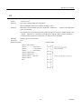
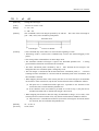
2.3
2.3.1
Paper Specifications
Recommended Paper
• Type
: Thermal paper
• Paper width
: 80 + 0/- 1 mm
• Paper thickness
: 60∼75µm
• Roll diameter
: φ83 mm or less
• Printing surface
: Outside of the roll (Surface)
• Recommended paper
: TF50KS-E2C (Monochrome) made by NIPPON SEISHI or its equivalent
• Core
: φ12 mm (Inner diameter), φ18 mm (Outer diameter)
CAUTION:
• Use of non-specified paper may cause irregularity of print density. If this is the case, use the DIP switch
to select print density. (See 5. DIP SWITCH SETTING)
• Do not paste the paper to the core.
• If the paper comes in contact with a chemical or oil, it may discolor or lose a record.
• Do not rub the paper surface strongly with a nail or hard metal. It may discolor.
•. Discoloring starts at about 70°C. Watch out for effects of heat, humidity, light, and so on.
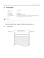
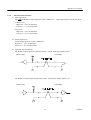
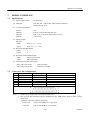
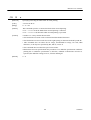
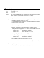
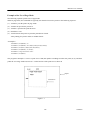
2.3.2
Printing Position
Paper Width: 80 mm
About 3.9 mm
Printing Area: 72.2 mm
5
About 3.9 mm
CITIZEN
iDP3221 User’s Manual
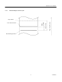
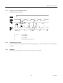
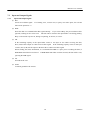
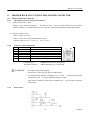
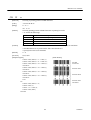
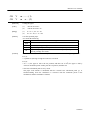
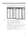
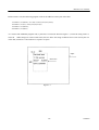
2.3.3
Head and Paper Cutter Layout
Paper Feed Direction
About
15.5 mm
Auto Cutter Position
About 42 mm
Paper Outlet
Head Printing Position
6
CITIZEN
iDP3221 User’s Manual
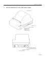
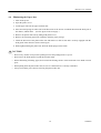
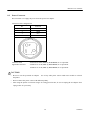
3.
OUTER APPEARANCE AND COMPONENT PARTS
Printer Cover
Upper Cover
Power Switch
POWER Lamp
ERROR Lamp
FEED Switch
Grounding Terminal
Drawer Kick-Out Connector
Interface Connector
Power Connector
7
CITIZEN
iDP3221 User’s Manual
4.
OPERATION
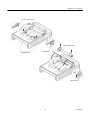
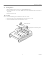
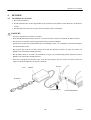
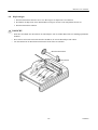
4.1
Connecting AC Adapter
1. Turn off the power.
2. With the flat surface on the AC adapter cable connector facing downwards, plug it into the power
connector at the rear of the printer.
3. Connect the AC power cord to the AC adapter, and plug it into an AC outlet.
CAUTION:
• Use only the specified AC adapter.
• When disconnecting/reconnecting the cable connector of the AC adapter, be sure to hold the connector.
• Separate the AC adapter from other noise-generating devices.
• Pulling the AC power cord may damage it, resulting in a fire, electric shock, or snapping.
• If a thunder/lightning storm is nearby, disconnect the AC adapter from the socket and do not use the printer,
because a fire or electric shock may occur.
• Do not put the AC power cord close to a heating device.
Its coating can melt and cause a fire or electric
shock.
• After using the printer or when not using it for a long period of time, be sure to unplug the AC adapter from
a plug socket for your safety.
Cable Connector
AC Adapter
AC Power Cord
Flat Surface
8
Power Connector
CITIZEN
iDP3221 User’s Manual
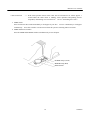
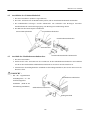
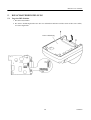
4.2
Connecting Interface Cable
1. Turn off the power.
(Mating side included)
2. Check the top and bottom of cable terminals, and connect to the interface connector.
3. Fix the cable terminals.
Serial interface
: Tighten screws, to fix it.
Parallel interface
: Turn clamps, to fix it.
4. Connect the cable to the host computer.
Serial Interface Cable
Serial Interface Connector
Parallel Interface Connector
Clamp
Parallel Interface Cable
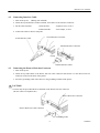
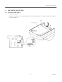
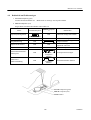
4.3
Connecting the Drawer Kick-Out Connector
1. Turn off the power.
2. Check the top and bottom of the drawer kick-out cable connector and connect it to the drawer kick-out
connector located on the back of the printer.
3. Screw the grounding cable of the drawer to the grounding terminal of the printer.
CAUTION:
• Connect only the prescribed drawer (Solenoid) to the drawer kick-out connector.
(Do not connect a telephone line.)
Drawer Kick-Out Connector
Drawer Kick-Out Cable Connector
Grounding Cable
9
CITIZEN
iDP3221 User’s Manual
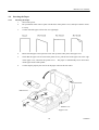
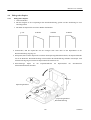
4.4
4.4.1
Inserting the Paper
Inserting the Paper
1.
Turn on the power.
2.
Put your hands in the concave parts on both sides of the printer cover, and open it until it comes
to a stop.
3.
Cut the end of the paper roll at close to a right angle.
4.
Ensure that the paper roll is placed correct side up in the roller part in the upper cover.
5.
Check that the paper roll is between the platen levers, pull the end of the paper out to the edge
of the upper cover, and close the printer cover.
The paper is automatically fed in and comes
out the paper outlet of the printer.
6.
Cut the surplus paper by the tear bar at the paper outlet of the auto cutter.
Concave Part
Platen Lever
Platen Lever
Upper Cover
10
CITIZEN
iDP3221 User’s Manual
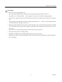
CAUTION:
• Be sure to use the specified paper roll.
• Use of non-specified paper may not guarantee the print quality, printing head life, and so on.
•
The printer cover is not detachable.
Do not apply an excessive force beyond its stopping position.
•
Do not insert a ragged or dog-eared end of the paper roll, because it could result in a paper jam or insertion
error.
•
Always pull the end of the paper roll out to the edge of the upper cover.
Take care to ensure that the paper
is not beyond or before the edge of the cover.
•
When the paper roll has been set in place, the end of the paper may be fed from the paper outlet in a folded
or creased condition. If the paper does not appear at the paper outlet, check the end of the paper and set it in
place again.
•
If the paper roll is skewed, pull the platen lever forward to correct its position.
•
Do not open the printer cover while printing.
•
Holding or touching the paper roll during printing may result in a paper jam.
•
When the auto cutter is used for full cutting, remove the cut paper before starting the next print operation to
prevent jamming.
11
CITIZEN
iDP3221 User’s Manual
4.4.2
Manually Inserting the Paper
The manual insertion is effective when DIP switch DS1-2 is set to ON to disable the cover open detection.
1.
Turn on the power.
2.
Put your hands in the concave parts on both sides of the printer cover, and open it until it comes
to a stop.
3.
Cut the end of the paper roll at close to a right angle.
4.
Ensure that the paper roll is placed correct side up in the roller part in the upper cover.
5.
Insert the end of paper roll straight between the platen roller and the printing head.
6.
The paper is automatically pulled into the platen roller and fed to the auto cutter (and comes out
of the paper outlet of the cutter a little).
7.
When the printer cover is closed, the paper is fed in a few more lines, cut, and printing is then
possible.
Remove cut paper before printing.
Concave Part
Upper Cover
12
CITIZEN
iDP3221 User’s Manual
CAUTION:
• Be sure to use the specified paper roll.
• Use of non-specified paper may not guarantee the print quality, printing head life, and so on.
•
The printer cover is not detachable.
Do not apply an excessive force beyond its stopping position.
•
Do not insert a ragged or dog-eared end of the paper roll, because it could result in a paper jam or insertion
error.
•
Rewind the paper roll if the paper is slack.
If there is too much slack in the paper roll, since the paper roll
is apart from the paper sensor, the printer may perform the operation described in 6. and 7. in 4.4.2
"Manually Inserting the Paper."
•
If the paper roll is skewed, pull the platen lever forward to correct its position.
•
When the paper roll has been set in place, the end of the paper may be fed from the paper outlet in a folded
or creased condition. If the paper does not appear at the paper outlet, check the end of the paper and set it in
place again.
•
Do not open the printer cover while printing.
•
Holding or touching the paper roll during printing may result in a paper jam.
• When the auto cutter is used for full cutting, remove the cut paper before starting the next print operation to
prevent jamming.
4.5
How to Remove Remaining Paper Roll
1. Open the printer cover.
2. Pull both platen levers in the direction of the arrow. The platen roller is then separated from the printing
head and the paper may then be removed.
CAUTION:
• When removing the paper (in either the
forward or reverse direction), pull the
platen levers in the direction of the arrow.
Platen Lever
13
CITIZEN
iDP3221 User’s Manual
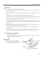
4.6
Eliminating the Paper Jam
1. Turn off the power.
2. Open the printer cover.
3. Cut the paper roll near the paper insertion slot.
4. Move the head springs on either side in the directions of the arrows to unhook them from the hook part of
the chassis, and lift them.
(See the figure on the next page.)
5. Remove the platen roller unit by lifting both platen levers.
6. Remove the remaining paper roll completely from the paper passage.
7. Check the direction of the platen roller unit and attach it so that its left end is securely engaged with the
bush guide of the chassis as shown in the figure.
8. While lightly holding the platen unit, hook the head springs on the hooks.
CAUTION:
• Do not carry out this work just after printing because the printing head is very hot.
• Do not move the head springs beyond the movable limits.
• When eliminating remaining paper, do not touch the heating surface of the head with a bare hand or metal
piece.
• When putting back the platen roller unit, be sure to confirm that it is correctly reattached.
• Always turn off the power before removing the platen roller unit.
14
CITIZEN
iDP3221 User’s Manual
Hook of the Chassis
Platen Roller Unit
Head Springs
Guide Bush
Guide Bush
15
CITIZEN
iDP3221 User’s Manual
4.7
Unlocking the Cutter
1. Remove the paper from the paper passage as described in 4.6 "Eliminating the Paper Jam."
2. Turn on the power.
The auto cutter initialization begins and the cutter returns to its home position.
Then, the alarm is cleared.
3. If the cutter does not return to its home position after the power has been turned on, do the following.
Turn off the power, and return the auto cutter blade to its home position by turning the emergency knob
on the bottom of the auto cutter in the direction indicated by the arrow, using tweezers, screwdrivers,
etc.
4. With tweezers or similar, totally remove remaining paper from the cutter blade area.
CAUTION:
• Do not carry out this work just after printing because the printing head is very hot.
• When eliminating remaining paper, do not touch the heating surface of the head with a bare hand or metal
piece.
• The cutter is enabled/disabled with the DIP switch.
sure that the cutter has returned to the home position.
When using the printer with the cutter disabled, be
If it is not, return it to the home position by turning
the emergency knob on the bottom of the printer.
Emergency Knob
16
CITIZEN
iDP3221 User’s Manual
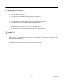
4.8
Cleaning the Head
1. Remove the platen roller unit referring to 4.6 "Eliminating the Paper Jam."
2. Clean the heating surface of the head by wiping it with a cotton swab dampened with a small amount of
ethyl alcohol.
3. Attach the platen roller unit.
CAUTION:
• Do not touch the heating surface of the head with a bare hand or metal.
•
Do not carry out this work just after printing because the printing head is very hot.
•
Always turn off the power before removing the platen roller unit.
Platen Roller Unit
Heating Surface of the Printing Head
Emergency Knob
17
CITIZEN
iDP3221 User’s Manual
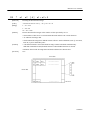
4.9
Operation Panel and Display of Error
1. POWER lamp (Green)
Illuminated if the power is turned on.
Also, flashes to indicate a memory error.
2. ERROR lamp (Red)
Indicates an error by illuminating or blinking the lamps.
Error
POWER Lamp
ERROR Lamp
Memory check error
Quick blinking
ON
Cover open
Reset
ON
Cannot be reset
ON
Close the cover.
Automatically reset by a
temperature drop
Set a new paper roll after a print
stop.
Set a new paper roll.
Head overheat
ON
Paper near end
ON
ON
Paper end
ON
ON
Cutter motor lock
ON
Macro execution wait
ON
Quick + Slow
blinking
Eliminate a paper jam.
Press the FEED switch.
Slow blinking
<Error Details>
Cover open
Head overheat
Paper near end
Paper end
----- Opening of the printer cover is detected by the printer cover open sensor. The
ERROR lamp is then lit and print operation is halted. Note that the DIP switch
may be set to allow paper feed while the printer cover is open.
----- If the temperature of the printing head rises (about 65°C or more), in order to protect
it against overheating, a printing head temperature sensor will be activated to stop
printing. If the temperature drops (about 60°C), printing will be automatically
resumed.
----- When the paper roll reaches a set diameter, the ERROR lamp is lit by the paper near
end sensor located on the side of the roller part of the upper cover. (See the
function of the control codes ESC c3 and ESC c4 in "PRINT CONTROL
FUNCTION.")
----- When the paper roll runs out, the paper sensor located in the paper path near the
printing head detects paper end and the ERROR lamp is lit, resulting in halting
printing. (See the function of the control codes ESC c3 and ESC c4 in "PRINT
CONTROL FUNCTION.") When paper is inserted into the paper path, loading of
the paper roll begins.
18
CITIZEN
iDP3221 User’s Manual
Cutter motor lock
----- If the cutter position sensor in the cutter unit is left turned on or off for approx. 1
second while the cutter motor is running, cutter operation and printing will be
suspended, determining it to be motor lock. See 4.7 "Unlocking the Cutter."
3. FEED switch
Press and release this switch immediately to feed paper by one line.
continuously.
Press it continuously to feed paper
Press this switch to execute macro when the system is awaiting macro-execution.
4. FEED and Power Switches
Press the FEED and POWER switches simultaneously to run self-print.
POWER Lamp (Green)
ERROR Lamp (Red)
FEED Switch
19
CITIZEN
iDP3221 User’s Manual
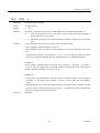
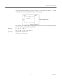
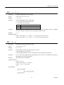
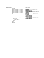
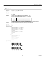
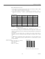
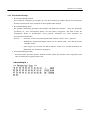
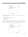
4.10 Hexadecimal Dumps
1. The Hexadecimal Dump Function
This function allows data sent from the host to be printed in hexadecimal notation, together with a
corresponding character printout.
2. Starting the Hexadecimal Dump
Press the POWER switch and FEED switch simultaneously with the cover opened.
When the cover is
closed, "Hexadecimal Dump" is printed on the paper and the received data is then printed in hexadecimal
format with the corresponding character printout.
Notes:
• "." is printed when the data has no corresponding character.
• Only the DLE EOT and DLE ENQ commands are usable during the hexadecimal dump.
• When less than one line of data is available for printing, pressing the FEEDswitch prints
a single line.
3. Terminating the Hexadecimal Dump
After the data has been printed, printing is terminated by either turning off the power, or by receipt of a
reset signal.
<Print Example>
20
CITIZEN
iDP3221 User’s Manual
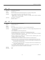
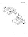
5.
DIP SWITCH SETTING
5.1
Location of DIP Switch
1. Turn off the power.
2. Remove the bottom cover by removing the two screws and turning it over in the direction shown by the
arrow to remove it.
Bottom Cover
21
CITIZEN
iDP3221 User’s Manual
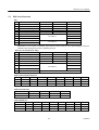
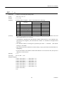
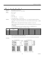
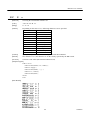
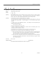
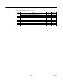
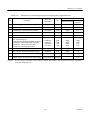
5.2
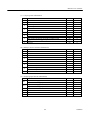
DIP Switch Function
DS1
No.
1
2
3
4
5
6
7
8
9
10
Function
Cutter
Cover open
CR switching
Kanji code selection
Input buffer
International character
“
ON
Enabled
Disabled
LF operation
S-JIS
72 bytes
OFF
Disabled
Enabled
Ignored
JIS
4 K bytes
Upon Shipment
ON
OFF
OFF
OFF
ON
OFF
OFF
OFF
ON
OFF
See Table 1.
“
Print density
“
See Table 2.
When DS1-2 "Cover open" is disabled, paper feed is possible with the cover open and paper insertion
method will be changed from auto to manual insertion.
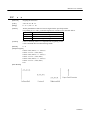
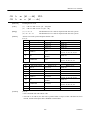
DS2 (For Serial Interface Only)
No.
1
2
3
4
5
Function
Bit length
Parity
Odd/Even
Communication mode
Baud rate
6
7
“
8
Unused
ON
7 bits
Yes
Even
XON/XOFF
OFF
8 bits
No
Odd
DTR/DSR
Upon Shipment
OFF
OFF
OFF
OFF
OFF
ON
ON
See Table 3.
“
Table 1 International character
DS1-6
DS1-7
DS1-8
USA
OFF
OFF
OFF
France
ON
OFF
OFF
Germany
OFF
ON
OFF
U.K.
ON
ON
OFF
Sweden
ON
OFF
ON
Denmark-I
OFF
OFF
ON
Italy
OFF
ON
ON
Japan
ON
ON
ON
9600
OFF
ON
ON
19200
ON
ON
ON
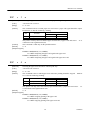
Table 2 Print density
Level 1
OFF
OFF
DS1-9
DS1-10
Level 2
ON
OFF
Level 3
OFF
ON
Level 4
ON
ON
Table 3 Baud rate
DS2-5
DS2-6
DS2-7
150
OFF
OFF
OFF
300
ON
OFF
OFF
600
OFF
ON
OFF
1200
ON
ON
OFF
22
2400
OFF
OFF
ON
4800
ON
OFF
ON
CITIZEN
iDP3221 User’s Manual
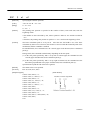
6.
PARALLEL INTERFACE
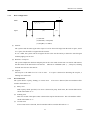
6.1
Bi-directional Parallel Interface (IEEE 1284)
6.1.1
Compatibility Mode (Host → Printer Communication Using the Centronics Interface)
(1) Outline
The familiar Centronics interface is used in the Compati bility mode.
(2) Specifications
6.1.2
Data transfer
:
8-bit parallel
Synchronization
:
External nStrobe signal
Handshaking
:
nAck and Busy signals
Signal level
:
All signals TTL compatible
Connector
:
57LE-40360 or equivalent (IEEE, 1284 Type B)
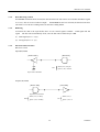
Reverse Mode (Printer → Host Communication)
Status data may be transferred from the printer to the host in either the Nibble or Byte mode.
Outline:
It is assumed that data is transferred from an asynchronous printer controlled from the host.
The existing control lines are used in transferring data in the Nibble mode (transferred in 4-bit units
(nibbles)).
Data is transferred in both directions on 8 data lines in the Byte mode (8-bit units (bytes)).
As simultaneous execution with the Compatibility mode is not possible, half-duplex communication is
employed.
See Appendix 2 for details.
23
CITIZEN
iDP3221 User’s Manual
6.1.3
Connector Pin Assignment
Pin No.
Source
Compatibility Mode
1
Host
nStrobe
2
Host/Printer
Data0(LSB)
3
Host/Printer
Data1
4
Host/Printer
Data2
5
Host/Printer
Data3
6
Host/Printer
Data4
7
Host/Printer
Data5
8
Host/Printer
Data6
9
Host/Printer
Data7(MSB)
10
Printer
nAck
11
Printer
Busy
12
Printer
PError
13
Printer
Select
14
Host
nAutoFd
15
(NC)
16
GND
17
FG
18
Printer
Logic-H
19
GND
20
GND
21
GND
22
GND
23
GND
24
GND
25
GND
26
GND
27
GND
28
GND
29
GND
30
GND
31
Host
nInit
32
Printer
nFault
33
GND
34
Printer
DK_STATUS
35
Printer
+5V
36
Host
nSelectIn
NC: Non connection
Nibble Mode
Byte Mode
HostClk
HostClk
Data0(LSB)
Data0(LSB)
Data1
Data1
Data2
Data2
Data3
Data3
Data4
Data4
Data5
Data5
Data6
Data6
Data7(MSB)
Data7(MSB)
PtrClk
PtrClk
PtrBusy/Data3.7
PtrBusy
AckDataReq/Data2.6
AckDataReq
XFlag/Data1.5
XFlag
HostBusy
HostBusy
(Undefined)
(Undefined)
GND
GND
FG
FG
Logic-H
Logic-H
GND
GND
GND
GND
GND
GND
GND
GND
GND
GND
GND
GND
GND
GND
GND
GND
GND
GND
GND
GND
GND
GND
GND
GND
nInit
nInit
nDataAvail/Data0.4
nDataAvail
(Undefined)
(Undefined)
(Undefined)
(Undefined)
(Undefined)
(Undefined)
IEEE 1284 Active
IEEE 1284 Active
•
"n" before the signal indicates that it is "L" active.
•
Bi-directional communication is impossible if any one of the above signals is absent.
•
Always use twisted-pair cables for signal lines, and connect return lines to signal ground.
•
Ensure that the interface employs TTL level signals with the following mentioned characteristics, and that
signal rise and fall times are 0.5 µsec.
•
Ignoring nAck and Busy signals while transferring data may result in loss of data.
•
Ensure that the interface cable is of the minimum length possible.
24
CITIZEN
iDP3221 User’s Manual
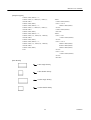
6.2
6.2.1
Parallel Interface (CENTRONICS)
Specifications
• Data input system
: 8-bit parallel (DATA1 to DATA8)
• Control signals
: ACK, BUSY, STB, FAULT, PE, RESET, SELECT, AUTO FEED, SELECT
IN
• Applicable connectors
: Printer side
Cable side
6.2.2
: 57LE-40360 (Anphenol) or its equivalent
: 57-30360 (Anphenol) or its equivalent
Connector's Pin Configuration
No.
1
2
3
4
5
6
7
8
9
10
11
12
13
14
15
16
17
18
Signal Name
STROBE
DATA 1
DATA 2
DATA 3
DATA 4
DATA 5
DATA 6
DATA 7
DATA 8
ACK
BUSY
PE
SELECT
AUTO FEED
GND
FRAME GND
25
No.
Signal Name
19
20
21
22
23
24
25
26
27
28
29
30
31
32
33
34
35
36
TWISTED PAIR GND
↑
↑
↑
↑
↑
↑
↑
↑
↑
↑
↑
RESET
FAULT
GND
Drawer Switch Output
+5V DC
SELECT IN
CITIZEN
iDP3221 User’s Manual
6.3
6.3.1
Input and Output Signals
Input and Output Signals
(1) Input signals to the printer
• DATA
: 8-bit parallel signal (Active High)
• STROBE
: Strobe signal to read the 8-bit data (Active Low)
• RESET
: Signal to reset the entire printer (Active Low); 1 ms or more
(2) Output signals from the printer
• ACK
: 8-bit data request signal.
A pulse signal to be output at the end of the BUSY signal
(Active Low)
• BUSY
: Signal to indicate that the printer is busy.
Input new data when it is "Low." (Active
High)
• FAULT
: Turned to "Low" when the printer has an alarm.
At this time, all the control circuits
in the printer stop. (Active Low)
• PE
: Output if the printing paper has run out or is running out. (Active High)
• Drawer Switch Output:
When connecting a drawer, turned to "High" if the switch is open. Turned to "Low" if
the switch is closed.
(3) Power source and the related
• GND
: Common ground for the circuits
26
CITIZEN
iDP3221 User’s Manual
6.3.2
Electrical Characteristics
(1) Input signal level
The STB and DATA1-8 input signals are at the C-MOS level.
Other input signals are at the TTL level.
C-MOS Level:
High level --- 4.0 V at minimum
Low level ---- 1.0 V at maximum
TTL Level:
High level --- 2.0 V at minimum
Low level ---- 0.8 V at maximum
(2) Output signal level
All the output signals are at the C-MOS level.
High level --- 2.4 V at minimum
Low level ---- 0.4 V at maximum
(3) Input and output conditions
The DATA1-8 input signals are pulled up at 50kΩ, and the other input signals at 50kΩ.
[Printer Side]
[Host Side]
The DATA1-8 output signals are pulled up at 50kΩ and the other output signals 3.3kΩ.
[Printer Side]
[Host Side]
27
CITIZEN
iDP3221 User’s Manual
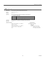
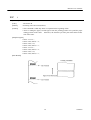
6.3.3
6.3.4
Timing Chart (Compatibility Mode)
Data Input and Print Timings
T1, T2, T3
0.5 µs MIN
T4
270 ns MAX
T5
2.3 µs TYP
T6
500 ms MIN (At power-on)
Data Receiving Control
The data can be received from the host when the BUSY signal is at "Low," but cannot be received when it
is "High."
6.3.5
Buffering
The host side is immediately freed, because 4 KB data can be buffered.
28
CITIZEN
iDP3221 User’s Manual
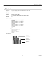
7.
SERIAL INTERFACE
7.1
Specifications
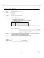
(1) Synchronous system
: Asynchronous
(2) Baud rate
: 150, 300, 600, 1,200, 2,400, 4,800, 9,600, 19,200 bps
(Selected by the user)
(3) 1-word configuration
Start bit
: 1 bit
Data bits
: 8 bits or 7 bits (Selected by the user)
Parity bit
: Odd, even, or no parity (Selected by the user)
Stop bit
: 1 bit or more
(4) Signal polarity
RS-232C
• Mark
= Logic "1" (-3 ∼ -12 V)
• Space
= Logic "0" (+3 ∼ +12 V)
(5) Received data (RD signal)
• Mark
= 1
• Space
= 0
(6) Reception control (DTR signal)
• Mark
:
Data not transferable
• Space
:
Data transferable
(7) Transmission control (TD signal)
7.2
• DC1 code(11H) X-ON
:
Data receivable
• DC3 code(13H) X-OFF
:
Data not receivable
Connector's Pin Configuration
No.
1
7
3
20
2
6
Signal Name
FG
GND
RD
DTR
TD
DSR
Input/Output
Input
Output
Output
Input
Function
Frame Ground
Signal Ground
Received Data
Printer BUSY Signal
Transmitted Data
Data Set Ready
Notes: 1. The RS-232C signals are based on the EIA RS-232C.
2. The received data should be always maintained in the Mark status when no data is being
transferred.
Applicable connectors (D-Sub connectors)
Printer side : 17LE-13250 (DDK) or its equivalent
Cable side
: 17JE-23250 (DDK) or its equivalent
29
CITIZEN
iDP3221 User’s Manual
7.3
Input and Output Signals
7.3.1
Input and Output Signals
(1) RD
Serial received data signal.
If a framing error, overrun error, or parity error takes place, the relevant
data will be printed as "?".
(2) DTR
Write the data or a command when this signal is Ready.
ignored, resulting in an overrun error.
If you write at Busy, the previous data will be
The data can be written in the input buffer even during printing.
Busy is also issued at power-on, during test printing, at on-line, or at reset.
(3) TD
If the remaining capacity of the input buffer comes to 128 bytes or less while receiving the data,
DC3(13H) will be output as a data not receivable signal.
If the remaining capacity comes to 256 bytes
or more, DC1(11H) will be output to the host side as a data receivable signal.
When sending the status information, it is confirmed that DSR is a space prior to sending the data, if
DTR/DSR control has been selected.
If DTR/DSR control has not been selected, the data will be sent,
ignoring the DSR signal.
(4) FG
Ground for the case
(5) GND
Common ground for the circuits
30
CITIZEN
iDP3221 User’s Manual
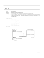
7.3.2
Data Configuration
t
Mark
b0, b1, b2, • • • •
Space
(1)
(2)
(3)
(1) Start Bit
(2) Data Bit (+ Parity Bit)
(3) Stop Bit (1 or More)
(1) Start bit
The system reads the status again after a lapse of 1/2 bit from a fall edge from the mark to space, and if
it is a space, this bit will be recognized as the start bit.
If it is a mark, the system will not recognize the bit as the start bit and try to detect the start bit again
without judging it as an error.
(2) Data bits + Parity bit
The system samples the data bits and parity bit for the 1 bit worth of time from 1/2 start bit and assumes
the then status as the data for the relevant bits.
The bits are called Bit 0, Bit 1, ..., Parity bit, counting
from the one closest to the start bit.
(3) Stop bit
The stop bit is the Mark level of 1 bit or more.
If a space is detected in detecting the stop bit, a
framing error will result.
7.3.3
Error Detection
The system detects a parity, framing, or overrun error.
If an error is detected, the relevant data will be
stored in the buffer as "?".
(1) Parity error
With a parity check specified, if an error is detected at parity check time, the relevant data will be
stored in the buffer as "?".
(2) Framing error
This error results if the Space status is detected at stop bit detection time. The relevant data will be
stored in the buffer as "?".
(3) Overrun error
If an overrun error is detected, the relevant data will be stored in the buffer as "?".
31
CITIZEN
iDP3221 User’s Manual
7.3.4
Data Receiving Control
If DTR/DSR control has been selected, the data from the host side will be received when the BUSY signal
is at "Low," but not received when at "High."
If DTR/DSR has not been selected, the data from the host
side will be received after sending XON, but not after sending XOFF.
7.3.5
Buffering
To transfer the data to the input buffer, there are two control signals available:
signal.
DTR signal and TD
The host side is immediately freed, since the data can be buffered up to 4 KB.
(1) DTR signal (See 7.3.1-(2))
(2) TD signal (See 7.3.1-(3))
7.3.6
Electrical Characteristics
RS-232C Circuit
Input (RD, DSR)
[Printer Side]
[Host Side]
Mark=(-8V): Stop bit
RD
Space=(+8V): Start bit
Equivalent to MAX232
Output (TD, DTR)
[Printer Side]
[Host Side]
Equivalent to MAX232
Mark=(-8V): At Busy
DTR
Mark=(-8V): 1
TD
Space=(+8V): At Busy
32
Space=(+8V): 0
CITIZEN
iDP3221 User’s Manual
8.
DRAWER KICK-OUT CONNECTOR, POWER CONNECTOR
8.1
Drawer Kick-Out Connector
8.1.1
Specifications of Drawer Kick-Out Connector
(1) Drawer kick-out drive signal
Outputs a pulse specified with ESC p.
The status of SW (+) can be checked with pin 34 on the parallel
interface connector, or with the DLE EOT, GS a, and GS r commands through the serial/parallel interface.
(2) Electrical characteristics
1) Drive voltage: 24 V DC
2) Drive current: 0.8 A at maximum (Within 510 ms)
3) Switch signal level: "L" = 0 to 0.5 V,
8.1.2
"H" = 3 to 5 V
Connector's Pin Configuration
No.
Signal
Function
1
FG
Frame Ground
2
DRAWER 1
Drawer 1 drive signal
3
DRSW
Drawer switch input
4
VDR
Drawer drive power
5
DRAWER 2
Drawer 2 drive signal
6
GND
Common ground on the circuit
Connector used
: TM5RJ3-66 (Hirose) or its equivalent
Applicable connector
: TM3P-66P (Hirose) or its equivalent
CAUTION : • No output is made while printing.
• The drawers 1 and 2 cannot be driven simultaneously.
• A solenoid used for the drawer should be of 36Ω or more.
be kept below 0.8 A.
An output current should
Use beyond this limit cannot be assured.
• This connector cannot be connected to a telephone line.
Do not connect other than
the solenoid.
8.1.3
Drive Circuit
33
CITIZEN
iDP3221 User’s Manual
8.2
Power Connector
This connector is to supply the power from the special AC adapter.
Connector's Pin Configurations
No.
Function
1
2
3
SHELL
+24V
GND
N.C
FG
Connector used
: TCS7960-53-2010 (Made by HOSHIDEN) or its equivalent
Applicable connector
: TCP8927-63-1100 (Made by HOSHIDEN) or its equivalent
TCP8927-53-1100 (Made by HOSHIDEN) or its equivalent
CAUTION:
• Be sure to use the specified AC adapter.
Use of any other power source could cause trouble to or break
the printer.
• Do not connect the power source with different polarity.
• After using the printer or when not using it for a long period of time, be sure to unplug the AC adapter from
a plug socket for your safety.
34
CITIZEN
iDP3221 User’s Manual
9.
MAINTENANCE AND SERVICE
For the information on maintenance and service, please contact our dealer or at the following address.
Northern America
Other Areas
CBM America Corporation
Japan CBM Corporation
Service Center
Information Systems Division
363 Van Ness Way
CBM Bldg., 5-68-10, Nakano
Suit 404
Nakano-ku, Tokyo 164-0001
Torrance, CA 90501, U.S.A
Japan
TEL
+1-310-781-1460
TEL
+81-3-5345-7540
FAX
+1-310-781-9157
FAX
+81-3-5345-7541
35
CITIZEN
iDP3221 User’s Manual
10. PRINT CONTROL FUNCTIONS
10.1 Command List
No.
Function
Command
Mode
Code
Page
1
HT
Horizontal tab
S,P
09H
40
2
3
LF
CR
S,P
S,P
0AH
0DH
41
41
4
FF
P
0CH
42
5
CAN
Printing and paper feed
Printing
Printing in Page mode and returning to Standard
mode
Canceling print data in Page mode
P
18H
42
6
DEL EOT
Sending status in real time
S,P
16H 04H n
43
7
DLE ENQ
Real-time request to printer
S,P
10H 05H n
46
8
ESC FF
Printing data in Page mode
P
1BH 0CH
47
9
ESC SP
Setting the right spacing of the character
S,P*
1BH 20H n
47
10
ESC !
Collective specifying the printing mode
S,P
1BH 21H n
49
11
ESC $
Specifying the absolute positions
S,P*
1BH 24H n1 n2
51
12
ESC %
Specifying/Canceling download character set
S,P
52
13
ESC &
Defining the download characters
S,P
14
ESC *
Specifying the bit image mode
S,P
15
ESC −
Specifying/Canceling underline
S,P
1BH 25H n
1BH 26H s n m [a
p1 p2…ps×a]
m-n+1
1BH 2AH m n1 n2
[d]k
1BH 2DH n
56
16
ESC 2
Specifying 1/6-inch line feed rate
S,P*
1BH 32H
57
17
ESC 3
Setting line feed rate of minimum pitch
S,P
1BH 33H n
58
18
ESC =
Data input control
S,P
1BH 3DH n
59
19
ESC ?
Deleting downloaded characters
S,P
1BH 3FH n
60
20
ESC @
Initializing the printer
S,P
1BH 40H
60
21
ESC D
Setting horizontal tab position
S,P
1BH 44H [n]k 00H
61
22
ESC E
Specifying/Canceling highlighting
S,P
1BH 45H n
62
23
ESC G
Specifying/Canceling double printing
S,P
1BH 47H n
63
24
ESC J
Printing and feeding paper in minimum pitch
S,P*
1BH 4AH n
64
25
ESC L
Selecting Page mode
S
1BH 4CH n
65
26
ESC R
Selecting the international character set
S,P
1BH 52H n
66
27
ESC S
P
1BH 53H n
67
28
ESC T
Selecting Standard mode
Selecting the character printing direction in Page
mode
P
1BH 54H n
68
In the Mode column:
53
54
S = Standard Mode, P = Page Mode
* shows the command affected by GS P.
36
CITIZEN
iDP3221 User’s Manual
No.
Function
Command
Mode
Code
Page
69
72
29
ESC V
Specifying/Canceling 90°-right-turned characters
S
30
ESC W
Defining the print area in Page mode
P*
31
ESC ¥
Specifying the relative position
S,P*
1BH 56H n
1BH 57H xH yH
dxL dxH dyL dyH
1BH 5CH nL nH
32
ESC a
S,P
1BH 61H n
73
33
ESC c 3
S,P
1BH 63H 33H n
74
34
ESC c 4
S,P
1BH 63H 34H n
74
35
ESC c 5
Aligning the characters
Selecting the paper near end sensor valid for a paper
end signal output
Selecting the paper near end sensor valid for print
stop
Enabling/Disabling the panel switches
S,P
1BH 63H 35H n
75
36
ESC d
Printing and feeding the paper by n lines.
S,P
1BH 64H n
75
37
ESC i
Full cut
S,P
1BH 69H
76
38
ESC m
Partial cut
S,P
1BH 6DH
77
39
ESC p
Generating the specified pulses
S,P
1BH 70H m n1 n2
78
40
ESC t
Selecting the character codes table
S,P
1BH 74H n
79
41
ESC {
Specifying/Canceling the inverted characters
S
1BH 7BH n
80
42
GS !
Specifying the character size
Specifying the absolute vertical
characters in Page mode
S,P
1DH 21H n
81
P*
1DH 24H nL nH
83
position
of
70
43
GS $
44
GS *
Defining the download bit image
S,P
45
GS /
Printing the downloaded bit image
S,P
1DH 2AH n1 n2
[d] n1×n2×8
1DH 2FH m
46
GS :
S,P
1D>H<3AH
87
47
GS B
S,P
1DH 42H n
88
48
GS H
Starting/Ending macro definition
Specifying/Canceling the black/white inverted
printing
Selecting of printing position of HRI characters
S,P
1DH 48H n
89
49
GS I
Sending the printer I
S,P
1DH 49H n
90
50
GS L
Setting the left margin
S*
1DH 4CH nL nH
91
51
GS P
Specifying the basic calculation pitch
S,P
1DH 50H x y
92
52
GS V
Cutting the paper
S,P
1DH 56H m
93
53
GS W
S,P
1DH 57H nL nH
94
54
GS ¥
S,P
1DH 5CH nL nH
96
55
GS ^
Setting the print area width
Specifying the relative vertical position of a
character in Page mode
Executing the macro
S,P
1DH 5EH n1 n2 n3
97
56
GS a
Enabling/Disabling ASB (Automatic Status Back)
S,P
1DH 61H n
98
In the Mode column:
84
86
S = Standard Mode, P = Page Mode
* shows the command affected by GS P.
37
CITIZEN
iDP3221 User’s Manual
No.
Function
Command
Mode
Code
Page
57
GS f
Selecting the font of HRI charactetrs
S,P
1DH 66H n
101
58
GS h
Specifying the height of the bar code
S,P
102
59
GS k
Printing the bar code
S,P
60
GS r
S,P
61
GS w
Sending status
Specifying the horizontal size (magnification) of bar
code
1DH 68H n
1DH 6BH m n
[d1 .... dn]
1DH 72H n
S,P
1DH 77H n
111
In the Mode column:
103
109
S = Standard Mode, P = Page Mode
* shows the command affected by GS P.
38
CITIZEN
iDP3221 User’s Manual
10.2 Command Details
10.2.1
Descriptions of Each Item
XXXXX
[Function]
Command Function
[Code]
A sequence of code constituting a command is represented in hexadecimal number for <
>H, binary number for <
>B, and decimal number for <
>, respectively; [
]k
represents a repeat count of k-times.
[Range]
Describes an argument value(Setting range) for the command.
[Outline]
Describes a command outline.
[Caution]
Describes a caution as required.
[Default]
Describes an initial value for the command when accompanied by an argument.
[See Also]
Describes the associated commands for use.
[Sample Program]
Describes a coding example in the Q-BASIC sample program.
This example is only for your reference and differs depending on the language used,
version, and so on.
[Print Result]
For details, see the manual for the language used.
Shows a print result obtained by running the above-mentioned program. However, the
print result shown here has a different scale from the actual print result.
XXXX
Represents the command.
39
CITIZEN
iDP3221 User’s Manual
10.2.2
Command Details
HT
[Function]
Horizontal tab
[Code]
<09> H
[Outline]
Shifts the printing position to the next horizontal tab position.
• Ignored when the next horizontal tab position has not been set.
[Caution]
• The horizontal tab position is set by ESC D.
• Initial setting of the horizontal tab position is each 8 characters in 9th, 17th, 25th, 33rd, and
41st columns.
[See Also]
ESC D
[Sample Program]
LPRINT "0123456789012345678901" ;
LPRINT CHR$ (&HA) ;
LPRINT CHR$ (&H9) ; "AAA" ;
LPRINT CHR$ (&H9) ; "BBB" ;
LPRINT CHR$ (&HA);
LPRINT CHR$ (&H1B) ; "D" ;
LPRINT CHR$ (3) ; CHR$ (7) ; CHR$ (14) ; CHR$ (0) ;
LPRINT CHR$ (&H9) ; "AAA" ;
LPRINT CHR$ (&H9) ; "BBB" ;
LPRINT CHR$ (&H9) ; "CCC" ; CHR$ (&HA) ;
END
[Print Results]
40
CITIZEN
iDP3221 User’s Manual
LF
Function]
Printing and paper feed
[Code]
<0A>H
[Outline]
Prints data inside the input buffer and feeds lines based on the line feed amount having been
set.
• The head of the line becomes the next print starting position.
[See Also]
ESC 2, ESC 3
[Sample Program]
[Print Results]
LPRINT "AAA" ; CHR$ (&HA) ;
LPRINT "BBB" ; CHR$ (&HA) ;
LPRINT CHR$ (&HA) ;
LPRINT "CCC" ; CHR$ (&HA) ;
END
CR
[Function]
Printing
[Code]
<0D>H
[Outline]
1) When DSW1-3 is OFF:
This command is ignored.
[See Also]
2) When DSW1-3 is ON:
With data held inside the internal print buffer, printing and line feed are performed.
Without data inside the internal print buffer, however, no printing is performed.
LF
[Sample Program]
[Print Results]
LPRINT "AAA" ; CHR$ (&HD) ;
When DSW1-3 is OFF
LPRINT "BBB" ; CHR$ (&HD) ;
AAABBBCCC
LPRINT CHR$ (&HD) ;
LPRINT "CCC" ; CHR$ (&HD) ;
When DSW1-3 is ON
END
41
CITIZEN
iDP3221 User’s Manual
FF
[Function]
Printing in Page mode and returning to Standard mode
[Code]
<0C>H
[Outline]
Executes a batch printout of the data mapped in the print area, and then returns to Standard
mode.
[Caution]
• All mapped data is erased after printout.
• The print area set up by ESC W is initialized.
• This command does not execute a paper cut.
• After this command is executed, the beginning of the line is taken as the start position for
the next print.
• This command is only effective when the Page mode is selected.
[See Also]
"Page Mode" in Appendix 1
ESC FF, ES L, ESC S
CAN
[Function]
Canceling print data in Page mode
[Code]
<18>H
[Outline]
Erases all data contained in the currently effective print area in Page mode.
[Caution]
• This command is only effective when Page mode is selected.
• If the previously established print area overlaps the currently effective print area, the
overlapped data in the previously established area will be erased.
[See Also]
ESC L, ESC W, "Page Mode" in Appendix 1
42
CITIZEN
iDP3221 User’s Manual
DLE
EOT
n
[Function]
Sending status in real time
[Code]
<10>H<04>H<n>
[Range]
1≤n≤4
[Outline]
Sends in real time the status specified by "n."
[Caution]
n = 1:
Printer status
n = 2:
Status caused by an offline condition
n = 3:
Status caused by an error
n = 4:
Paper detector status
• Each status represents the current status. It is 1-byte data.
• The status is transferred without checking whether the host is ready to receive or busy.
• This command is executed even if the printer is in offline state, receive-buffer full state, or
error state.
• This command is dealed with when it is received.
• If another data string of <16>H<04>H<n> (1 ≤ n ≤ 4) is received, the printer acts the same
way as with this command. Therefore, the user should be reminded of this fact.
[Example 1]
Suppose a command "ESC * m nL nH [d1 ... dk]," where d1 = <10>H, d2 = <04>H, d3 =
<01>H.
• The DLE EOT n command cannot be interleaved into the code string of another command
consisting of two bytes or more.
[Example 2]
If the printer sends DLE EOT 3 when the host has sent down to ESC 3 in its attempt to send
ESC 3 n, the printer handles the ESC 3 as ESC 3 <10>H. Thus, the user should be cautious.
• If ASB (automatic status back) is enabled by GS a, it is necessary to discriminate between
the status due to AS and the status due to this command.
43
CITIZEN
iDP3221 User’s Manual
(1) Printer status (when n = 1 is specified)
Bit
0
1
2
3
4
5
6
7
Status
Unused
Unused
Status of pin 3 of drawer kick connector = L
Status of pin 3 of drawer kick connector = H
Online status
Offline status
Unused
Undefined
Undefined
Unused
Hex.
00
02
00
04
00
08
10
00
Decimal
0
2
0
4
0
8
16
0
(2) Status caused by an offline condition (when n = 2 is specified)
Bit
0
1
2
3
4
5
6
7
Status
Hex.
00
02
00
04
00
08
10
00
20
00
40
00
Unused
Unused
Cover closed
Cover open
Not in paper feed state triggered by FEED switch
In paper feed state triggered by FEED switch
Unused
Printing is not stopped because of "paper out" state
Printing is stopped because of "paper out" state
Error not occurred
Error occurred
Unused
Decimal
0
2
0
4
0
8
16
0
32
0
64
0
Bit 5: Printing is stopped if the paper end detector detects a "paper out" state, or if the printer
is out of paper when the paper near-end detection is enabled by ESC4.
At this time,
bit 5 = "1."
(3) Status caused by an error (when n = 3 is specified)
Bit
0
1
2
3
4
5
6
7
Status
Unused
Unused
Undefined
Auto cutter error not occurred
Auto cutter error occurred
Unused
Unrecoverable error not occurred
Unrecoverable error occurred
Auto recovery error not occurred
Auto recovery error occurred
Undefined
44
Hex.
00
02
00
08
10
00
20
00
40
00
Decimal
0
2
0
8
16
0
32
0
64
0
CITIZEN
iDP3221 User’s Manual
Bit 3: If this error occurred because of a paper jam, for example, remove the cause of the error,
and then DEL ENQ n (1 ≤ n ≤ 2) can be used to recover from the error.
However, it is
not possible to recover from any error due to a circuit problem (e.g., broken wire).
Bit 6: If a head overheat error is detected and the printing is stopped until the head
temperature falls.
At this time, bit 6 = "1."
(4) Paper detector status (when n = 4 is specified)
Bit
0
1
2,3
4
5,6
7
[See Also]
Status
Unused
Unused
Paper not found by paper near end detector
Unused
Paper found by paper end detector
Paper not found by paper end detector
Unused
Hex.
00
02
00
10
00
60
00
Decimal
0
2
0
16
0
96
0
DLE ENQ, GS a, and GS r, "Identification of Send Status" in Appendix 3
45
CITIZEN
iDP3221 User’s Manual
DLE
ENQ
n
[Function]
Real-time request to printer
[Code]
<10>H<05>H<n>
[Range]
1 ≤≤ n ≤ 2
[Outline]
The printer responds in real time to the request that the host specified with number "n."
[Caution]
n = 1:
After recovering from an error, the printer resumes printing from the beginning of
the line where the error occurred.
n = 2:
The printer clears the receive buffer and the print buffer, and then recovers from the
error.
• This command is only effective if an auto cutter error has occurred.
• This command is dealt with when it is received.
• This command is also executed even if the printer is in a receive-buffer full state or error
state.
• If another data string of <10>H<05>H<n> (1 ≤ n ≤ 2) is received, the printer acts in the
same way as with this command. The user should, therefore, be reminded of this fact.
[Example 1]
If, for example, a command "ESC * m nL nH {d} k," where d1 = <10>H, d2 = <05>H, d3 =
<01>H, is given, the DLE ENQ n command cannot be interleaved into the code string of
another command consisting of two bytes or more.
[Example 2]
• If the printer sends DLE ENQ 2 when the host has sent down to ESC 3 in its attempt to
send ESC 3 n, the printer treats the ESC 3 as ESC 3 <10>H. Thus, the user should be
careful.
• When DEL ENQ 2 is executed, the settings made by, for example, ESC ! and ESC 3 remain
the same as those in effect when the error occurred. A combined use of this command and
ESC @ can completely initialize the printer.
[See Also]
DLE EOT
46
CITIZEN
iDP3221 User’s Manual
ESC
FF
[Function]
Printing data in Page mode
[Code]
<1B>H<0C>H
[Outline]
Executes a batch printout of the data mapped in every print area in Page mode.
[Caution]
• This command is only effective when Page mode is selected.
• Mapped data, as well as the ESC T and ESC W settings, and the character mapping
position are held even after printing.
[See Also]
"Page Mode" in Appendix 1
FF, ESC L, ESC S
ESC
SP
n
[Function]
Setting the right spacing of the character
[Code]
<1B> H <20> H <n>
[Range]
0 ≤ n ≤ 32
[Outline]
Sets the right spacing of character to [n × basic calculation pitch] inches.
[Caution]
• If the horizontal magnification of character is 2 or more, the right spacing increases with
the magnification.
• This command does not affect kanji characters.
• The right spacing can be set separately for the Standard and Page modes.
• The basic calculation pitch is set by GS P. Once defined, the right spacing is not changed
if the basic calculation pitch is changed by GS P.
• Fractions resulting from calculation are corrected with the minimum pitch of the
mechanism, and the remainder is omitted.
• In Standard mode, this command uses the horizontal basic calculation pitch (x).
• In Page mode, the basic calculation pitch used by this command depends on the start point:
(1) If the start point specified by ESC T is top left or bottom right, the command uses the
horizontal basic calculation pitch (x).
(2) If the start point specified by ESC T is top right or bottom left, the command uses the
vertical basic calculation pitch (y).
• The maximum settable right spacing is approximately 35.983 mm (255/180 inches).
setting greater than this maximum is trimmed to the maximum.
[Default]
n=0
[See Also]
GS P
47
A
CITIZEN
iDP3221 User’s Manual
[Sample Program]
LPRINT CHR$ (&H1B) ; "
[Print Results]
" ; CHR$ (0) ;
LPRINT "AAAAA" ; CHR$ (&HA) ;
LPRINT CHR$ (&H1B) ; "
" ; CHR$ (1) ;
LPRINT "AAAAA" ; CHR$ (&HA) ;
LPRINT CHR$ (&H1B) ; "
" ; CHR$ (12) ;
LPRINT "AAAAA" ; CHR$ (&HA)
END
48
CITIZEN
iDP3221 User’s Manual
ESC
!
n
[Function]
Collective specifying the printing mode
[Code]
<1B> H <21> H <n>
[Range]
0 ≤ n ≤ 255
[Outline]
Printing mode is assigned.
Bit
0
1
2
3
4
5
6
7
[Caution]
Each "n" bit indicates the following:
Value
Function
0
1
Character Font
Font A
Font B
Undefined
Undefined
High-lighting
Canceled
Specified
Double height
Canceled
Specified
Double width
Canceled
Specified
Undefined
Underline
Canceled
Specified
• With double height and double width being specified simultaneously, double wide and
double high characters are consisted.
• An underline is attached to the full character width, which, however, is not attached to the
part having been skipped by the horizontal tab. Neither is it attached to 90°-right-turned
characters.
• The underline width is as having been specified by the "ESC −" command.
setting is 1 dot width. )
(The default
• Specification with this command is invalid to Kanji, except specification and cancellation of
highlighting.
• In case that double wide character and normal character exist in same one line, the layout of
underline is consistent one.
[Default]
n=0
[See Also]
ESC E, ESC −, GS !
[Sample Program]
LPRINT CHR$ (&H1B) ; " ! " ; CHR$ (&H00) ; "H" ;
LPRINT CHR$ (&H1B) ; " ! " ; CHR$ (&H01) ; "H";
LPRINT CHR$ (&H1B) ; " ! " ; CHR$ (&H08) ; "H";
LPRINT CHR$ (&H1B) ; " ! " ; CHR$ (&H10) ; "H";
LPRINT CHR$ (&H1B) ; " ! " ; CHR$ (&H20) ; "H";
LPRINT CHR$ (&H1B) ; " ! " ; CHR$ (&H80) ; "H";
LPRINT CHR$ (&H1B) ; " ! " ; CHR$ (&HB9) ; "H";
LPRINT CHR$ (&HA) ;
END
49
CITIZEN
iDP3221 User’s Manual
[Print Results]
50
CITIZEN
iDP3221 User’s Manual
ESC
$
n1
n2
[Function]
Specifying the absolute positions
[Code]
<1B> H <24> H < n1> <n2>
[Range]
0 ≤ n1 ≤ 255
0 ≤ n2 ≤ 1
[Outline]
The printing start position is specified in the number of dots (1/203 inch unit) from the
beginning of line.
• The number of dots is divided by 256, whose quotient is taken as "n2" and the residual as
"n1."
• Therefore, the printing start position is equal to n1 + n2 × 256 from the beginning of line.
[Caution]
The basic calculation pitch is set by GS P. After the line feed width is set, if the basic
calculation by GS P leaves a fraction, the fraction is corrected with the minimum pitch of the
mechanism, and the remainder is omitted.
In Standard mode, this command uses the vertical (paper feed direction) basic calculation
pitch (y).
In Page mode, this command acts differently depending on the start point:
(1) If the start point specified by ESC T is top left or bottom right, the command uses the
vertical (paper feed direction) basic calculation pitch (y).
(2) If the start point specified by ESC T is top right or bottom left, the command uses the
horizontal (perpendicular to the paper feed direction) basic calculation pitch (x).
Specification beyond the end of the line is ignored.
[Default]
The initial value is not specified.
[See Also]
ESC ¥, GS P, GS Y, GS $
[Sample Program]
[Print Results]
LPRINT CHR$ (&H1B) ; "$" ;
LPRINT CHR$ (0) ; CHR$ (0) ; "A" ;
LPRINT CHR$ (&H1B) ; "$" ;
LPRINT CHR$ (50) ; CHR$ (0) ; "B" ;
LPRINT CHR$ (&H1B) ; "$" ;
LPRINT CHR$ (0) ; CHR$ (1) ; "C" ;
LPRINT CHR$ (&HA) ;
LPRINT CHR$ (&H1B) ; "$" ;
LPRINT CHR$ (100) ; CHR$ (0) ; "A" ;
LPRINT CHR$ (&H1B) ; "¥" ;
LPRINT CHR$ (&HC2) ; CHR$ (&HFF) ; "B" ;
LPRINT CHR$ (&HA) ;
END
51
CITIZEN
iDP3221 User’s Manual
ESC
%
n
[Function]
Specifying/Canceling download character set
[Code]
<1B> H <25> H <n>
[Range]
0 ≤ n ≤ 255
[Outline]
Specifying/canceling download characters.
Further, only the lowest bit (n0) is valid for n.
The lowest bit (n0) indicates the following.
n0
0
1
Function
Canceling download character set
Specifying download character set
[Caution]
Download characters and download bit images cannot be defined simultaneously.
[Default]
n=0
[See Also]
ESC &
[Sample Program]
GOSUB *SETCHR
DATA
6
LPRINT CHR$ (&H1B) ; "%" ; CHR$ (0) ;
DATA
&HFF, &H80, &H00
LPRINT "@A" ; CHR$ (&HA) ;
DATA
&H80, &H80, &H00
LPRINT CHR$ (&H1B) ; "%" ; CHR$ (1) ;
DATA
&H80, &H80, &H00
LPRINT "@A" ; CHR$ (&HA) ;
DATA
&H80, &H80, &H00
END
DATA
&HFF, &HFF, &HFF
DATA
&HFF, &HFF, &HFF
LPRINT CHR$ (&H1B) ; "&" ;
DATA
12
LPRINT CHR$ (3) ; "@" ; "A" ;
DATA
&HFF, &HFF, &HFF
FOR J=1 TO 2
*SETCHR :
DATA
&H80, &H07, &HF9
READ REP
DATA
&H80, &HFF, &HF9
LPRINT CHR$ (REP) ;
DATA
&H87, &HFE, &H01
FOR I=1 TO REP∗3
DATA
&H9F, &H06, &H01
READ D
DATA
&HF8, &H06, &H01
LPRINT CHR$ (D) ;
DATA
&HF8, &H06, &H01
DATA
&H9F, &H06, &H01
NEXT J
NEXT I
DATA
&H87, &HFE, &H01
RETURN
DATA
&H80, &HFF, &HF9
DATA
&H80, &H07, &HF9
DATA
&HFF, &HFF, &HFF
[Print Results]
52
CITIZEN
iDP3221 User’s Manual
ESC
&
s
n
m
[a [p] s×a]
m−n+1
[Function]
Defining the download characters
[Code]
<1B> H <26> H <s> <n> <m> [<a> <p1> <p2> … <ps×a>] m-n+1
[Range]
s=3
32 ≤ n ≤ m ≤ 126
0 ≤ a ≤ 12 (Font A)
0 ≤ a ≤ 9 (Font B)
[Outline]
0 ≤ p1 •• ps×a ≤ 255
Defines the font of download characters of alphanumeric characters.
• "s" indicates the number of bytes in vertical direction.
• "n" indicates the start character code and "m" the end character code. To define only one
character, set n=m.
• Character codes definable includes 95 ASCII codes in total between 32∼126.
• "a" indicates the number of dots in horizontal direction for definition.
• "p" is the data to be defined, which indicate a pattern equal to "a" dot in horizontal direction
from the left end. The rest of the pattern on the right side is filled with space.
The rest of data to be defined is s×a.
• Download characters thus defined remain valid until redefinition, ESC @ execution, GS
execution, or power OFF is practiced.
[Caution]
∗
Download characters and download bit images cannot be defined simultaneously.
Running this command clears the definition of the download bit image.
[Default]
Same as the internal character set
[See Also]
ESC %
[Example]
Create each data bit by setting "1" for a printed dot and "0" for an unprinted dot.
[Sample Program]
[Print Results]
See Sample Program and Print Results for ESC % on page 52.
53
CITIZEN
iDP3221 User’s Manual
ESC
*
m
n1
n2
[d]
k
[Function]
Specifying the bit image mode
[Code]
<1B> H <2A> H <m> <n1> <n2> [<d>] k
[Range]
m= 0, 1, 32, 33
0 ≤ n1 ≤ 255
0 ≤ n2 ≤ 3
0 ≤ d ≤ 255
[Outline]
k = n1 + 256 × n2
(m = 0, 1)
k = (n1+ 256 × n2) × 3
(m = 32, 33)
According to the number of dots specified in "n1," "n2," specify the bit image of mode "m."
• The number of dots printed is divided by 256, whose quotient is taken as n2 and
as "n1."
residual
• The total number. of dots printed in the bit image is equal to n1 + (256 × n2).
• When bit image data have been input in excess of dot position of one line, the excess data
are discarded.
• "d" is bit image data, the bits subject to printing are taken as "1" and those not as "0".
• The bit image modes specified by m are shown as follows:
m
Mode
0
1
32
33
8-dot single density
8-dot double density
24-dots single density
24-dots double density
[Caution]
Vertical Direction
No. of Dots
Dot Density
8
60 DPI
8
60 DPI
24
203 DPI
24
203 DPI
Horizontal Direction
Dot Density
Max. No. of Dots
n1 + n2×256
90 DPI
n1 + n2×256
180 DPI
(n1+n2
×256)×3
90 DPI
(n1+n2×256)×3
180 DPI
• When the values set in m (Bit image mode) are out of the above range, the data following
after n1 is processed as normal printing data.
• After completion of bit image printing, printer returns to normal data processing mode.
[Example]
54
CITIZEN
iDP3221 User’s Manual
[Sample Program]
LPRINT CHR$ (&H1B) ; "∗" ;
LPRINT CHR$ (0) ; CHR$ (20) ; CHR$ (0) ;
*IMG1:
GOSUB *IMG1
LPRINT CHR$ (&HFF) ;
LPRINT CHR$ (&HA) ;
FOR I=1 TO 18
LPRINT CHR$ (&H1B) ; "∗" ;
LPRINT CHR$ (&H85) ;
LPRINT CHR$ (1) ; CHR$ (20) ; CHR$ (0) ;
NEXT I
GOSUB *IMG1
LPRINT CHR$ (&HFF) ;
LPRINT CHR$ (&HA) ;
RETURN
LPRINT CHR$ (&H1B) ; "∗" ;
*IMG2 :
LPRINT CHR$ (32) ; CHR$ (20) ; CHR$ (0) ;
GOSUB *IMG2
FOR I=1 TO 3
LPRINT CHR$ (&HFF) ;
LPRINT CHR$ (&HA) ;
NEXT I
LPRINT CHR$ (&H1B) ; "∗" ;
FOR I=1 TO 18
LPRINT CHR$ (33) ; CHR$ (20) ; CHR$ (0) ;
LPRINT CHR$ (&H80) ;
GOSUB *IMG2
LPRINT CHR$ (&H00) ;
LPRINT CHR$ (&HA) ;
LPRINT CHR$ (&H05) ;
END
NEXT I
FOR I=1 TO 3
LPRINT CHR$ (&HFF) ;
NEXT I
RETURN
[Print Results]
8-dots single density
8-dots double density
24-dots single density
24-dots double density
55
CITIZEN
iDP3221 User’s Manual
ESC
−
n
[Function]
Specifying/Canceling underline
[Code]
<1B> H <2D> H <n>
[Range]
0≤n≤2
[Outline]
Specifying/canceling an underline.
• Types of underlines by "n" value are shown below:
n
0
1
2
[Caution]
Type
Canceling an underline
Specifying an underline for 1-dot width
Specifying an underline for 2-dots width
• An underline is attached to the full character width.
having been skipped by horizontal tab command.
It is, however, not attached to the part
• An underline is not attached to a 90 °- right-turned characters.
• Specification/cancellation with this command is invalid to Kanji.
[Default]
n=1
[See Also]
ESC !
[Sample Program]
LPRINT CHR$ (&H1B) ; "−" ; CHR$ (0) ;
LPRINT "AAAAA" ;
LPRINT CHR$ (&H1B) ; "−" ; CHR$ (1) ;
LPRINT "AAAAA" ; CHR$ (&HA) ;
END
[Print Results]
56
CITIZEN
iDP3221 User’s Manual
ESC
2
[Function]
Specifying 1/6-inch line feed rate
[Code]
<1B> H <32> H
[Outline]
The line feed rate per line is specified by 1/6 inch.
[Sample Program]
[Print Results]
LPRINT "AAAAA" ; CHR$ (&HA) ;
LPRINT CHR$ (&H1B) ; "3" ; CHR$ (0) ;
1/6-inch line feed
LPRINT "AAAAA" ; CHR$ (&HA) ;
0/156-inch line feed
LPRINT CHR$ (&H1B) ; "3" ; CHR$ (50) ;
50/156-inch line feed
LPRINT "AAAAA" ; CHR$ (&HA) ;
1/6-inch line feed
LPRINT CHR$ (&H1B) ; "2" ;
LPRINT "AAAAA" ; CHR$ (&HA) ;
LPRINT "AAAAA" ;
LPRINT CHR$ (&H1B) ; "J" ; CHR$ (100) ;
100/156-inch line feed
1/6-inch line feed
LPRINT "AAAAA" ; CHR$ (&HA) ;
LPRINT "AAAAA" ; CHR$ (&HA) ;
57
CITIZEN
iDP3221 User’s Manual
ESC
3
n
[Function]
Setting line feed rate of minimum pitch
[Code]
<1B> H <33> H <n>
[Range]
0 ≤ n ≤ 255
[Outline]
Sets the line feed width per line to [n × basic calculation pitch] inches.
[Caution]
The line feed width can be set separately for the Standard and Page modes.
The basic calculation pitch is set by GS P. Once defined, the line feed width is not changed
if the basic calculation pitch is changed by GS P.
Fractions resulting from calculation are corrected with the minimum pitch of the mechanism,
and the remainder is omitted.
• In Standard mode, this command uses the vertical (paper feed direction) basic calculation
pitch (y).
• In Page mode, this command acts differently depending on the start point:
(1) If the start point specified by ESC T is top left or bottom right, the command uses the
vertical (paper feed direction) basic calculation pitch (y).
(2) If the start point specified by ESC T is top right or bottom left, the command uses the
horizontal (perpendicular to the paper feed direction) basic calculation pitch (x).
The maximum settable line feed width is 1016 mm (40 inches).
maximum is trimmed to the maximum.
[Default]
4.23 mm
[See Also]
ESC 2, ESC c1, GS P
58
A setting greater than this
CITIZEN
iDP3221 User’s Manual
ESC
=
n
[Function]
Data input control
[Code]
<1B> H <3D> H <n>
[Range]
0 ≤ n ≤ 255
[Outline]
Selecting equipment in which data input from the host is effective.
• Each bit of "n" indicates as follows:
Bit
Equipment
0
1
2
3
4
5
6
7
Printer
Not defined
Not defined
Not defined
Not defined
Not defined
Not defined
Not defined
Value
0
Invalid
1
Valid
• When the printer has not been selected, this printer abandons all the received data until it is
selected by this command.
[Caution]
• Even when the printer has not been selected, it can become BUSY state through printer
operation.
• When the printer is deselected, this printer discards all the data until it is selected with this
command. (Except DLE ENQ1 and DLE ENQ2)
[Default]
n=1
[See Also]
DLE ENQ
[Sample Program]
[Print Results]
LPRINT "AAAAA" ;
LPRINT CHR$ (&H1B) ; "=" ; CHR$ (0) ;
LPRINT "aaaaa" ; CHR$ (&HA) ;
LPRINT CHR$ (&H1B) ; "=" ; CHR$ (1) ;
LPRINT "AAAAA" ; CHR$ (&HA) ;
59
CITIZEN
iDP3221 User’s Manual
ESC
?
n
[Function]
Deleting downloaded characters
[Code]
<1B>H<3F>H<n>
[Outline]
Deletes the downloaded characters of specified code.
[Caution]
• The character "n" indicates the character code used to delete the defined pattern. After the
deletion, characters are printed in the same pattern as the internal characters.
• This command deletes the code-defined pattern of the character font selected by ESC !.
• This command is ignored if the specified character code is undefined.
[See Also]
ESC
ESC &, ESC %
@
[Function]
Initializing the printer
[Code]
<1B> H <40> H
[Outline]
Clears data stored in the print buffer and brings various settings to the initial state (default
state).
[Caution]
• Data inside the internal input buffer are not cleared.
• DIP switches settings are red once again.
[Sample Program]
[Print Results]
LPRINT CHR$ (&H1B) ; " ! " ; CHR$ (&H30) ;
LPRINT CHR$ (&H1B) ; "V" ; CHR$ (1) ;
LPRINT "AAA" ; CHR$ (&HA) ;
LPRINT CHR$ (&H1B) ; "@" ;
Each setting has been
initialized by this
command.
LPRINT "AAA" ; CHR$ (&HA) ;
60
CITIZEN
iDP3221 User’s Manual
ESC
D
[Function]
[Code]
[Range]
[Outline]
[n]
k
NUL
Setting horizontal tab position
<1B> H <44> H [<n>] k <00> H
1 ≤ n ≤ 255
0 ≤ k ≤ 32
Specifying a horizontal tab position.
• "n" indicates the number of columns from the beginning to the horizontal tab position. At
this time, "n= set position− 1" is to be specified. For example, to set the position at 9th
column, n=8 is to be specified.
• "k" denotes the number of horizontal tab positions you want to set.
• The tab position is set at position where it is "character width×n" from the line beginning.
The character width, at this time, includes the rightward space amount. In double wide
characters, it is made double of the ordinary case.
• Tab positions can be specified are maximum 32.
Specifying exceeding this is ignored.
• <n> k, which denotes a setting position, is input in the increasing order and ends at <00> H.
[Caution]
• ESC D NUL clears all the set tab positions. Following clearing, horizontal tab command
is ignored.
When the data, <n> k, is equal to or smaller than its preceding data, <n> k-1, it is assumed
that tab setting is finished. If this is the case, the next data onward will be processed as
normal data.
When the data, <n> k, exceeds a 1-line print area, set the horizontal tab position, assuming
"Set digit position = Maximum print digits + 1." The horizontal tab position does not
change even if the character width is altered after setting the horizontal tab position.
[Default]
• Initial value is specified for each eight characters (9th., 17th., 25th. columns) of Font A.
[See Also]
HT
[Sample Program]
[Print Results]
See Sample Program and Print Results for HT on page 40.
61
CITIZEN
iDP3221 User’s Manual
ESC
E
n
[Function]
Specifying/Canceling highlighting
[Code]
[Range]
<1B> H <45> H <n>
0 ≤ n ≤ 255
[Outline]
Specifying/canceling the highlighting characters.
• "n" is valid only for the lowest bit (n0).
• Control by the lowest bit (n0) is shown as follows:
n0
0
1
Type
Canceling highlighting
Specifying highlighting
• This is effective to all characters.
[See Also]
[Example]
• Dot configuration of a highlighted character includes one extra dot added at its side.
ESC !
[Sample Program]
[Print Results]
LPRINT CHR$ (&H1B) ; "E" ; CHR$ (0) ;
LPRINT "AAABBB" ; CHR$ (&HA) ;
LPRINT CHR$ (&H1B) ; "E" ; CHR$ (1) ;
LPRINT "AAABBB" ; CHR$ (&HA) ;
62
CITIZEN
iDP3221 User’s Manual
ESC
G
[Function]
[Code]
[Range]
[Outline]
n
Specifying/Canceling double printing
<1B> H <47> H <n>
0 ≤ n ≤ 255
Specifying/canceling the double printing.
• "n" is valid only for the lowest bit (n0).
• Control by "n" is shown as follows.
n0
0
1
Type
Canceling double printing
Specifying double printing
This is effective to all characters.
[Caution]
The print result of double printing and highlight character printing is completely same.
[See Also]
ESC E
[Sample Program]
[Print Results]
LPRINT CHR$ (&H1B) ; "G" ; CHR$ (0) ;
LPRINT "AAABBB" ; CHR$ (&HA) ;
LPRINT CHR$ (&H1B) ; "G" ; CHR$ (1) ;
LPRINT "AAABBB" ; CHR$ (&HA) ;
63
CITIZEN
iDP3221 User’s Manual
ESC
J
n
[Function]
Printing and feeding paper in minimum pitch
[Code]
<1B> H <4A> H <n>
[Range]
0 ≤ n ≤ 255
[Outline]
Prints the data held in the print buffer and feeds paper by n/360 inches.
the line is taken as the start position for the next print.
[Caution]
The line feed width can be set separately for the Standard and Page modes.
The beginning of
This command does not affect the line feed width defined by ESC 2 or ESC 3.
The basic calculation pitch is set by GS P.
Fractions resulting from calculation are corrected with the minimum pitch of the mechanism,
and the remainder is omitted.
In Standard mode, this command uses the vertical (paper feed direction) basic calculation
pitch (y).
In Page mode, this command acts differently depending on the start point:
(1) If the start point specified by ESC T is top left or bottom right, the command uses the
vertical (paper feed direction) basic calculation pitch (y).
(2) If the start point specified by ESC T is top right or bottom left, the command uses the
horizontal (perpendicular to the paper feed direction) basic calculation pitch (x).
The maximum settable line feed width is 1016 mm (40 inches). A setting greater than
this maximum is trimmed to the maximum. The beginning of the line is taken as the
start position for the next print.
[Default]
Undefined
[Sample Program]
[Print Results]
See Sample Program and Print Results for ESC 2 on page 57.
64
CITIZEN
iDP3221 User’s Manual
ESC
L
[Function]
Selecting Page mode
[Code]
<1B>H<4C>H<n>
[Outline]
Switches from Standard mode to Page mode.
[Caution]
• This command is only effective if it entered at the beginning of a line.
• This command is not effective if it is entered when in Page mode.
• Standard mode is restored when printing specified by FF is finished or when ESC S is
issued.
• The character mapping start position will be the point specified by ESC T in the print area
specified by ESC W.
• The commands listed below, which have separate settings for Page mode and Standard
mode, are changed to the settings for Page mode use.
(1) Spacing setting:
ESC SP
(2) Line feed width setting:
ESC 2, ESC 3
• In Page mode, the following commands can only be set.
(1) ESC V
Specifying/changing to 90°-right-turned characters.
(2) ESC a
Aligning the characters.
(3) ESC {
Specifying/canceling the inverted characters.
(4) GS L
Setting the left margin.
(5) GW W
Setting the print area width.
ESC @ restores Standard mode.
[See Also]
"Page Mode" in Appendix 1
FF, CAN, ESC FF, ESC S, ESC T, ESC W, GS S, GS ¥
65
CITIZEN
iDP3221 User’s Manual
ESC
R
n
[Function]
Selecting the international character set
[Code]
<1B> H <52> H <n>
[Range]
0 ≤ n ≤ 10
[Outline]
Depending on the value of "n," following character sets are specified.
n
0
1
2
3
4
5
6
7
8
9
10
Character Set
U.S.A.
France
Germany
U.K.
Denmark I
Sweden
Italy
Spain
Japan
Norway
Denmark II
[Caution]
Spain, Norway, and Denmark II can only be set with this command.
[Default]
The default of "n" is the character set for the country specified by the DIP switch.
[See Also]
Character Code Table (International Character Set)
[Sample Program]
FOR I=0 TO 10
LPRINT CHR$ (&H1B) ; "R" ; CHR$ (I) ;
LPRINT " #$@[¥]^" ;
LPRINT CHR$ (&H60) ; " { ¦ }∼ " ;
LPRINT "n=" ; STR$ (I) ;
LPRINT CHR$ (&HA) ;
NEXT I
END
[Print Results]
66
CITIZEN
iDP3221 User’s Manual
ESC
S
[Function]
Selecting Standard mode
[Code]
<1B>H<53>H<n>
[Outline]
Switches from Page mode to Standard mode.
[Caution]
• This command is only effective if it is entered when in Page mode.
• Any data mapped in Page mode is erased.
• After this command is executed, the beginning of the line is taken as the start position for
the next print command.
• The print area defined by ESC W is initialized.
• The commands listed below, which have separate settings for Standard mode and Page
mode, are changed to the settings for Standard mode use.
(1) Spacing setting:
ESC SP
(2) Line feed width setting:
ESC 2, ESC 3
• Standard mode is selected when the printer is turned on or when ESC @ is executed.
[See Also]
FF, ESC FF, ESC L
67
CITIZEN
iDP3221 User’s Manual
ESC
T
n
[Function]
Selecting the character printing direction in Page mode
[Code]
<1B>H<54>H<n>
[Range]
0 ≤ n ≤ 3, 48 ≤ n ≤ 51
[Outline]
Selects the direction and start position of character printing in Page mode.
n
0,48
1,49
2,50
3,51
Printing direction
Left to right
Bottom to top
Right to left
Top to bottom
Start point
Top left ("A" in the figure)
Bottom left ("B" in the figure)
Bottom right ("C" in the figure)
Top right ("D" in the figure)
Paper Feed Direction
Print Area
[Caution]
• When Standard mode is selected, this command only executes the internal flagging of the
printer without affecting the printing in Standard mode.
• The character mapping position will be the start position in the print area specified by ESC
W.
• The basic pitch (x or y) used by the following commands varies with the start point.
(1) If the start point is the top left or bottom right (the characters are mapped in the
direction perpendicular to the paper feed).
• Commands using x:
ESC SP, ESC S, ESC ¥
• Commands using y:
ESC 3, ESC J, GS S, GS ¥
(2) If the start point is the top right or bottom left (the characters are mapped in the paper
feed direction).
• Commands using x:
ESC 3, ESC J, GS S, GS ¥
• Commands using y:
ESC SP, ESC S, ESC ¥
[Default]
n=0
[See Also]
"Page Mode" in Appendix 1
ESC $, ESC L, ESC W, ESC ¥, GS $, GS P, GS ¥
68
CITIZEN
iDP3221 User’s Manual
ESC
V
n
[Function]
Specifying/Canceling 90°-right-turned characters
[Code]
<1B> H <56> H <n>
[Range]
0≤n≤ 1
[Outline]
Specifying/canceling characters 90°-right- turned character.
• "n" means the followings.
n
0
1
Condition
Canceling 90°-right- turned Characters
Specifying 90°-right- turned Characters
[Caution]
No underlines are attached to 90°-right- turned characters .
[Default]
n=0
[Sample Program]
[Print Results]
LPRINT CHR$ (&H1B) ; "V" ; CHR$ (0) ;
LPRINT "AAAAA" ;
LPRINT CHR$ (&H1B) ; "V" ; CHR$ (1) ;
LPRINT "AAAAA" ; CHR$ (&HA) ;
END
69
CITIZEN
iDP3221 User’s Manual
ESC
W
xL
xH
yL
yH
dxL
dxH
dyL
dyH
[Function]
Defining the print area in Page mode
[Code]
<1B>H<57>H<xH><yH><dxL><dxH><dyL><dyH>
[Range]
0 ≤ xL, xH, yL, yH, dxL, dxH, dyL, dyH ≤ 255, except for dxL = dxH = 0 or dyL = dyH = 0
[Outline]
Defines the location and size of the print area.
• Horizontal start point = [(xL + xH ( 256) ( basic calculation pitch] inches
• Vertical start point = [(yL + yH ( 256) ( basic calculation pitch] inches
• Horizontal length = [(dxL + dxH ( 256) ( basic calculation pitch] inches
• Vertical length = [(dyL + dyH ( 256) ( basic calculation pitch] inches
[Caution]
• When Standard mode is selected, this command only executes the internal flagging of the
printer without affecting the printing in Standard mode.
• If the horizontal start point or vertical start point is out of the printable area, this command
is canceled and the next data is handled as normal data.
• If the horizontal length or vertical length is 0, this command is canceled and the next data is
handled as normal data.
• The character mapping position will be the start point specified by ESC T in the print area.
• If the "horizontal start point + horizontal length" is greater than the horizontal printable area,
the "horizontal printable area - horizontal start point" is taken as the horizontal length.
• If the "vertical start point + vertical length" is greater than the vertical printable area, the
"vertical printable area - vertical start point" is taken as the vertical length.
• The print area is defined by the basic calculation pitch GS P. Once defined, the print area
is not changed if the basic calculation pitch is changed by GS P.
• Fractions resulting from calculations are corrected with the minimum pitch of the
mechanism, and the remainder is omitted.
• The horizontal start point and horizontal length are calculated with the basic calculation
pitch (x). The vertical start point and vertical length are calculated with the basic calculation
pitch (y).
70
CITIZEN
iDP3221 User’s Manual
• The figure below illustrates the print area, where X = horizontal start point, Y = vertical
start point, Dx = horizontal length, and Dy = vertical length.
Paper
Print Area
Paper Feed Direction
The printable area for this printer is approximately 72.249 mm (512/180 inches) horizontally
and 117.263 mm (1662/360 inches) vertically.
[Default]
xL = xH = yL = yH = 0
dxL = 0, dxH = 2, dyL = 126, dyH = 6
[See Also]
"Page Mode" in Appendix 1
CAN, ESC L, ESC T, GS P
71
CITIZEN
iDP3221 User’s Manual
ESC
¥
nL
nH
[Function]
Specifying the relative position
[Code]
<1B> H <5C> H <nL><nH>
[Range]
0 ≤ nL ≤ 255
0 ≤ nH ≤ 255
[Outline]
This command specifies the start position for the next print in terms of a relative position
with respect to the current position. The start position for the next print will be at a distance
of [(nL + nH × 256) × basic calculation pitch] inches away the current position.
[Caution]
• Specification of a position outside the print area is ignored.
• The new position to be specified for the character of interest will be positive ("+") if it is to
the right of the current position. It will be negative ("-") if it is to the left of the current
position.
• A negative value is the complement of 65536.
pitches to the left, specify it as:
For example, to move the position by N
nL + nH × 256 = 63356 - N
• The basic calculation pitch is set by GS P.
• Fractions resulting from calculation are corrected with the minimum pitch of the
mechanism, and the remainder is omitted.
• In Standard mode, this command uses the horizontal basic calculation pitch (x).
• In Page mode, this command acts differently depending on the start point:
(1) If the start point specified by ESC T is top left or bottom right, the command specifies
the relative position in the direction perpendicular to the paper feed (the character’s
side-to-side direction), using the horizontal basic calculation pitch (x).
(2) If the start point is top right or bottom left, the command specifies the relative position
in the paper feed direction (the character’s side-to-side direction), using the vertical
basic calculation pitch (y).
[See Also]
ESC $, GS P
[Sample Program]
[Print Results]
See Sample Program and Print Results for ESC $ on page 51.
72
CITIZEN
iDP3221 User’s Manual
ESC
a
n
[Function]
Aligning the characters
[Code]
<1B> H <61> H <n>
[Range]
0 ≤ n ≤ 2, 48 ≤ n ≤ 50
[Outline]
All the printed data within one line are aligned in the specified position.
• Depending on "n" value, positional alignment is carried out as in the table below:
n
0,48
1,49
2,50
[Caution]
Position
Left end alignment
Centering
Right end alignment
• This is valid only when "n" is inputted at the beginning of line.
• This command does not affect the Page mode.
[Default]
n=0
[Sample Program]
LPRINT CHR$ (&H1B) ; "a" ; CHR$ (0) ;
LPRINT "AAAAA" ; CHR$ (&HA) ;
LPRINT CHR$ (&H1B) ; "a" ; CHR$ (1) ;
LPRINT "AAAAA" ; CHR$ (&HA) ;
LPRINT CHR$ (&H1B) ; "a" ; CHR$ (2) ;
LPRINT "AAAAA" ; CHR$ (&HA) ;
END
[Print Results]
73
CITIZEN
iDP3221 User’s Manual
ESC
c
3
n
[Function]
Selecting the paper near end sensor valid for a paper end signal output
[Code]
<1B>H<63>H<33>H<n>
[Range]
0 ≤ n ≤255
[Outline]
This command selects at which paper near end sensor a paper end signal should be output.
Each bit for "n" has the following meaning:
Value
Bit
Position
0
1
0
Paper near end
Disabled
Enabled
Undefined
1∼7
This printer can only select one kind of paper end detection, a paper-near-end sensor.
valid for the least significant bit (n0).
[Caution]
This command is valid only for the parallel interface.
[Default]
n=0
[Sample Program]
LPRINT CHR$(&H1B);"c3";CHR$(0);
•••••••When outputting the paper-end signal at the paper end
LPRINT CHR$(&H1B);"c3";CHR$(1);
•••••••When outputting the paper-end signal at the paper near end
ESC
c
4
"n" is
n
[Function]
Selecting the paper near end sensor valid for print stop
[Code]
<1B>H<63>H<34>H<n>
[Range]
0 ≤ n ≤ 255
[Outline]
This command selects at which paper near end sensor printing should be stopped.
for "n" has the following meaning:
Value
Bit
Position
0
1
0
Paper near end
Disabled
Enabled
Undefined
1∼7
Each bit
This printer can only select one kind of paper-end detection, a paper-near-end sensor.
is valid for the least significant bit (n0).
[Default]
n=0
[Sample Program]
LPRINT CHR$(&H1B);"c4";CHR$(0);
•••••••When stopping printing at the paper end
LPRINT CHR$(&H1B);"c4";CHR$(1);
•••••••When stopping printing at the paper near end
74
"n"
CITIZEN
iDP3221 User’s Manual
ESC
c
5
n
[Function]
Enabling/Disabling the panel switches
[Code]
<1B> H <63> H <35> H <n>
[Range]
0 ≤ n ≤ 255
[Outline]
Selecting the FEED switch valid/invalid.
• "n" is valid only in the lowest bit (n0).
• "n" bit means the followings.
n0
0
1
Condition
FEED switch valid.
FEED switch invalid.
[Caution]
When the panel switch is disabled with this command, the FEED switch is disabled.
Therefore, the paper cannot be fed by operating the FEED switch.
[Default]
n=0
[Sample Program]
LPRINT CHR$ (&H1B) ; "c5" ; CHR$ (0) ; ••••••• When enabling the FEED switch
LPRINT CHR$ (&H1B) ; "c5" ; CHR$ (1) ; ••••••• When disabling the FEED switch
ESC
d
n
[Function]
Printing and feeding the paper by n lines
[Code]
<1B> H <64> H <n>
[Range]
0 ≤ n ≤ 255
[Outline]
Prints data in the buffer and feeds paper by "n" lines.
• Specified line does not remain.
• The beginning of the line is to be considered as the next printing start position.
[Caution]
If [n × line feed width] exceeds approximately 1016 mm, this command feeds paper by
approximately 1016 mm (40 inches).
[Default]
The initial value is not defined.
[Sample Program]
LPRINT "AAAAA"
LPRINT CHR$ (&H1B) ; "d" ; CHR$ (2) ;
LPRINT "AAAAA" ; CHR$ (&HA) ;
END
[Print Results]
75
CITIZEN
iDP3221 User’s Manual
ESC
i
[Function]
Full cut
[Code]
<1B>H<69>H
[Outline]
Activating auto cutter unit (Full cut)
[Caution]
• This command is valid only when it is inputted at the beginning of line.
• Prior to cutting the paper, feed the paper from the printing position to beyond the paper
cutting position of the cutter. Otherwise, the character just after print will remain on this
side of the cutter.
[Sample Program]
LPRINT "AAAAA" ;
LPRINT CHR$ (&H1B) + "J" ;
LPRINT CHR$ (150) ;
LPRINT CHR$ (&H1B) + "i" ;
LPRINT "AAAAA" ;
LPRINT CHR$ (&H1B) + "J" ;
LPRINT CHR$ (150) ;
LPRINT CHR$ (&H1B) + "i" ;
[Print Results]
76
CITIZEN
iDP3221 User’s Manual
ESC
m
[Function]
Partial cut
[Code]
<1B>H<6D>H
[Outline]
Activating auto cutter unit (Partial cut)
[Caution]
• This command is valid only when it is inputted at the beginning of line.
• Prior to cutting the paper, feed the paper from the printing position to beyond the paper
cutting position of the cutter. Otherwise, the character just after print will remain on this
side of the cutter.
[Sample Program]
LPRINT "AAAAA" ;
LPRINT CHR$ (&H1B) + "J" ;
LPRINT CHR$ (150) ;
LPRINT CHR$ (&H1B) + "m" ;
LPRINT "AAAAA" ;
LPRINT CHR$ (&H1B) + "J" ;
LPRINT CHR$ (150) ;
LPRINT CHR$ (&H1B) + "m" ;
[Print Results]
77
CITIZEN
iDP3221 User’s Manual
ESC
p
m
n1
n2
[Function]
Generating the specified pulses
[Code]
<1B>H<70>H<m><n1><n2>
[Range]
m = 0, 1
0 < n1 ≤ n2 ≤ 255
[Outline]
The signals specified by "n1" and "n2" are output to the connector pin specified by "m".
• "m" has the followings.
m
0
1
Connector Pin
Drawer kick pin No.2
Drawer kick pin No.5
• The ON time is n1×2 ms, and OFF time n2×2 ms.
[Caution]
• When "m" is beyond a definition range, no signal is output, discarding "n1" and "n2."
• A drawer drive duty is as follows.
ON time
≤ 0.2
ON time + OFF time
(The OFF time should be 4 times or more larger than the ON time.)
[Default]
The initial value for "m", "n1" and "n2" is not defined.
[Sample Program]
LPRINT CHR$ (&H1B) + "p"
LPRINT CHR$ (0) ; ••••••• Selects pin No. 2.
LPRINT CHR$ (5) ; ••••••• Sets ON time to 10ms
LPRINT CHR$ (50) ; ••••••• Sets OFF time to 100ms
END
78
CITIZEN
iDP3221 User’s Manual
ESC
t
n
[Function]
Selecting the character code table
[Code]
<1B>H<74>H<n>
[Range]
0 ≤ n ≤ 5, n = 255
[Outline]
Selecting page "n" on the character code table:
The character code table is selected depending on the value of "n."
"n" means the followings.
n
0
1
2
3
4
5
255
Page on the Character Code Table
Page 0
Page 1
Page 2
Page 3
Page 4
Page 5
Page 255 (blank page)
[Default]
n=0
[See Also]
Character Code Table
[Sample Program]
LPRINT CHR$ (&H1B) + "t" + CHR$ (0) ;
LPRINT " n=0
";
FOR C=&HB1 TO &HB5
LPRINT CHR$ (C) ;
NEXT C
LPRINT CHR$ (&HA) ;
LPRINT CHR$ (&H1B) + "t" + CHR$ (1) ;
LPRINT " n=1
";
FOR C=&HB1 TO &HB5
LPRINT CHR$ (C) ;
NEXT C
LPRINT CHR$ (&HA) ;
[Print Results]
n=0
n=1
79
CITIZEN
iDP3221 User’s Manual
ESC
{
n
[Function]
Specifying/Canceling the inverted characters
[Code]
<1B>H<7B>H<n>
[Range]
0 ≤ n ≤ 255
[Outline]
Specifying/canceling inverted characters.
• "n" is valid only for the lowest bit (n0).
• Bit "n" (n0) means the followings.
n0
0
1
[Caution]
Condition
Canceling inverted characters.
Specifying inverted characters.
• Inverted printing means printing the line at 180°turned.
• This command is valid only when it is specified at the beginning of a line.
• This command does not affect the Page mode.
[Default]
n=0
[Sample Program]
LPRINT CHR$ (&H1B) + "{" + CHR$ (0) ;
LPRINT "AAAAA" + CHR$ (&HA) ;
LPRINT "BBBBB" + CHR$ (&HA) ;
LPRINT CHR$ (&H1B) + "{" + CHR$ (1) ;
LPRINT "AAAAA" + CHR$ (&HA) ;
LPRINT "BBBBB" + CHR$ (&HA) ;
[Print Results]
80
CITIZEN
iDP3221 User’s Manual
GS
!
n
[Function]
Specifying the character size
[Code]
<1D>H<21>H<n>
[Range]
0 ≤ n ≤ 255, where:
1 ≤ vertical magnification ≤ 8, and 1 ≤ horizontal magnification ≤ 8
[Outline]
Specifies the character size (vertical and horizontal magnification).
Bit
Meaning
0
1
2
3
4
5
6
7
Hex. Number
Vertical magnification
specification
See Table 2, "Vertical Magnification"
Horizontal magnification
specification
See Table 1, "Horizontal Magnification"
Table 1 Horizontal Magnification
[Caution]
Value
Decimal Number
Table 2 Vertical Magnification
Hex.
Decimal
Magnification
Hex.
Decimal
Magnification
00
0
00
0
10
16
01
1
20
30
40
50
60
70
32
48
64
80
96
112
1×(standard)
2×(horizontal
double)
3×
4×
5×
6×
7×
8×
02
03
04
05
06
07
2
3
4
5
6
7
1×(standard)
2×(vertical
double)
3×
4×
5×
6×
7×
8×
• This command works for all alphanumeric characters except for HRI characters.
• This command is ignored if either the vertical magnification or horizontal magnification is
out of range.
• In Standard mode, the vertical direction is defined as the paper feed direction, and the
horizontal direction is defined as the direction perpendicular to the paper feed. These
definitions are, therefore, interchanged when 90°-right-turned characters are specified.
• In Page mode, the vertical direction means the top-bottom direction of each character.
The horizontal direction means the side-to-side direction of each character.
81
CITIZEN
iDP3221 User’s Manual
• If characters of different vertical magnification are contained in a line, the baseline of each
character is lined up.
• Horizontal and vertical magnification can also be specified/canceled by ESC !. The ESC !
or GS ! command, whichever is handled last, becomes effective.
[Default]
n=0
[See Also]
ESC !
82
CITIZEN
iDP3221 User’s Manual
GS
$
nL
nH
[Function]
Specifying the absolute vertical position of characters in Page mode
[Code]
<1D>H<24>H<nL><nH>
[Range]
0 ≤ nL ≤ 255
0 ≤ nH ≤ 255
[Outline]
[Caution]
This command is used in Page mode to specify the vertical position of characters at the data
mapping start position as an absolute value measured from the start point. The vertical
position of a character at the next data mapping start position will be at a distance of [(nL +
nH ( 256) ( basic calculation pitch] inches away from the start point.
• This command is ignored when Page mode is not selected.
• Any specification of absolute vertical position out of the printable area is ignored.
• The horizontal position of a character at the data mapping start position is not moved.
• The start point used as the reference is specified by ESC T.
• Depending on the start point specified by ESC T, this command acts as follows:
(1) If the start point is the top left or bottom right, the command specifies the absolute
position in the paper feed direction (the character's top-bottom direction), using the
vertical basic calculation pitch (y).
(2) If the start point is the top right or bottom left, the command specifies the absolute
position in the direction perpendicular to the paper feed (the character's top-bottom
direction) using the horizontal basic calculation pitch (x).
• The basic calculation pitch is set by GS P.
• Fractions resulting from calculations are corrected with the minimum pitch of the
mechanism, and the remainder is omitted.
[See Also]
ESC $, ESC T, ESC W, ESC ¥, GS P, GS ¥
83
CITIZEN
iDP3221 User’s Manual
GS
*
n1
n2
[d]
n1 × n2 × 8
[Function]
Defining the download bit image
[Code]
<1D>H<2A>H<n1><n2> [ < d > ] n1 × n2 × 8
[Range]
1 ≤ n1 ≤ 255
1 ≤ n2 ≤ 48
n1 × n2 ≤ 1536
[Outline]
Defines download bit images of the number of dots specified by n1/n2.
• The numbers of dots are n1×8 in horizontal direction and n2×8 in vertical direction.
• "d" indicates bit image data.
• The download bit image thus defined remains effective until redefinition, ESC @ execution,
ESC &, or power OFF takes place.
[Caution]
• A download character and a download bit image cannot be defined simultaneously.
With this command executed, defined content of a downloaded character is cleared.
• Relations between the bit image data and the dot defined are shown below:
[See Also]
GS /
n1×8 dots
n2×8 dots
84
CITIZEN
iDP3221 User’s Manual
[Sample Program]
[Print Results]
GOSUB IMG
LPRINT CHR$ (&H1D) + "/" + CHR$ (0) ;
LPRINT CHR$ (&H1D) + "/" + CHR$ (1) ;
LPRINT CHR$ (&H1D) + "/" + CHR$ (2) ;
LPRINT CHR$ (&H1D) + "/" + CHR$ (3) ;
END
IMG :
n 1 = 10 : n 2= 5
LPRINT CHR$ (&H1D) + "∗" ;
LPRINT CHR$ (n1) + CHR$ (n2) ;
FOR J=1 TO n1∗8
FOR I=1 TO n2
LPRINT CHR$ (J) ;
NEXT I
NEXT J
RETURN
85
CITIZEN
iDP3221 User’s Manual
GS
/
m
[Function]
Printing the downloaded bit image
[Code]
<1D>H<2F>H<m>
[Range]
0≤m≤3
48 ≤ m ≤ 51
[Outline]
Prints downloaded bit image in a mode specified by "m."
Modes can be selected by "m" are shown below.
[Caution]
m
Mode Name
0,48
1,49
2,50
3,51
Normal mode
Double wide mode
Double high mode
Double wide/double high mode
Dot Density in
Vertical Direction
180 DPI
180 DPI
90 DPI
90 DPI
Dot Density in
Horizontal Direction
180 DPI
90 DPI
180 DPI
90 DPI
• When data exist in the print buffer, this command is ignored.
• When a downloaded bit image has not been defined, this command is ignored.
• A portion of a downloaded bit image exceeding one line length is not printed.
• A downloaded character and a downloaded bit image cannot be defined simultaneously.
[Default]
The initial value is not specified.
[See Also]
GS *
[Sample Program]
[Print Results]
See Sample Program and Print Results for GS * on page 84.
86
CITIZEN
iDP3221 User’s Manual
GS
:
[Function]
Starting/Ending macro definition
[Code]
<1D>H<3A>H
[Outline]
Specifying starting/ending macro definition.
Means termination when received while defining a macro.
[Caution]
Maximum content available for macro definition is 2048 bytes.
bytes is not defined.
A portion exceeding 2048
• Even with ESC @ (initialization of the printer) having been executed, defined content is not
cleared. Therefore, it is possible to include ESC @ into the content of macro definition.
• Normal printing operation is carried out even while in macro definition.
[Default]
Initially, macro is not specified.
[See Also]
GS ^
[Sample Program]
[Print Results]
LPRINT CHR$ (&H1D) + " : " ;
LPRINT "+ − − − +" + CHR$ (&HA) ;
LPRINT "|
|" + CHR$ (&HA) ;
LPRINT "+ − − − +" + CHR$ (&HA) ;
LPRINT CHR$ (&H1D) + " : " ;
LPRINT CHR$ (&H1D) + " ^ " ;
LPRINT CHR$ (2) + CHR$ (10) ;
LPRINT CHR$ (0) ;
END
87
CITIZEN
iDP3221 User’s Manual
GS
B
n
[Function]
Specifying/Canceling the black/white inverted printing
[Code]
<1D>H<42>H<n>
[Range]
0 ≤ n ≤ 255
[Outline]
This command specifies or cancels the black/white inverted printing.
• If n = <*******0>B, the black/white inverted printing is canceled.
• If n = <*******1>B, the black/white inverted printing is specified.
[Caution]
• Number "n" is only valid in the lowest bit.
• The black/white inversion works on internal and downloaded characters.
• The black/white inversion works also on the right spacing of characters defined by ESP SP.
• This command does not affect the bit image, downloaded bit image, bar code, HRI
characters, or the skip area specified by HT, ESC $, or ESC ¥.
• This command does not affect the space between lines.
• Black/white inversion specification take precedence over underline specification. Underline
printing due to underline specification is, therefore, nullified if black/white inversion is
specified; the underline setting, however, remains unchanged.
[Default]
n=0
88
CITIZEN
iDP3221 User’s Manual
GS
H
n
[Function]
Selecting of printing position of HRI characters
[Code]
<1D>H<48>H<n>
[Range]
0≤n≤3
48 ≤ n ≤ 51
[Outline]
Selecting printing position of HRI characters in printing bar codes.
• "n" means the followings.
n
0,48
1,49
2,50
3,51
[Caution]
Printing Position
No printing
Above the bar code
Below the bar code
Both above and below the bar code
• The HRI characters refer to the bar code-turned characters so that you can read them.
• The HRI characters are printed in the font selected with GS f.
• Specify before the GS k command.
[Default]
n=0
[See Also]
GS f, GS k
[Sample Program]
[Print Results]
LPRINT CHR$ (&H1B) + "3" + CHR$ (5) ;
LPRINT CHR$ (&H1D) + "h" + CHR$ (50) ;
LPRINT CHR$ (&H1D) + "H" + CHR$ (0) ;
No HRI
characters
GOSUB BC
LPRINT CHR$ (&H1D) + "H" + CHR$ (1) ;
Printed above
GOSUB BC
LPRINT CHR$ (&H1D) + "H" + CHR$ (2) ;
GOSUB BC
LPRINT CHR$ (&H1D) + "H" + CHR$ (3) ;
Printed below
GOSUB BC
END
Printed above
and below
BC :
LPRINT CHR$ (&H1D) + "k" ;
LPRINT CHR$ (4) ;
LPRINT "12" + CHR$ (0) ;
LPRINT CHR$ (&HA) ;
RETURN
89
CITIZEN
iDP3221 User’s Manual
GS
I
n
[Function]
Sending the printer ID
[Code]
<1D>H<49>H<n>
[Range]
0≤n≤3
49 ≤ n ≤ 51
[Outline]
Sends the specified printer ID.
"n" means the following.
n
1,49
2,50
3,51
Type of printer ID
Model ID
Type ID
ROM version ID
Specification
Value (hex)
iDP3221
20
See table below "Type ID"
As per ROM version
Type ID
Bit
0
1
2
3
4
5
6
7
[Caution]
Meaning
Equipped for 2-byte code support
Equipped with autocutter
Undefined
Undefined
Unused
Undefined
Undefined
Unused
Hex.
Decimal
01
02
—
—
00
—
—
00
1
2
—
—
0
—
—
0
• Under DTR/DSR control, the printer sends the printer ID after verifying that the host is
ready to receive. If the host is not ready to receive, the printer waits for the host to
become ready to receive.
• Under XON/OFF control, the printer sends the printer ID without checking whether the
host is ready to receive or busy.
• Because this command is executed when data is mapped in the receive buffer, there may be
a delay between command receiving and printer ID sending depending on the condition of
the receive buffer.
• If ASB (automatic status back) is enabled by GS a, the host must discriminate between the
printer ID due to this command and the status due to ASB.
90
CITIZEN
iDP3221 User’s Manual
GS
L
nL
nH
[Function]
Setting the left margin
[Code]
<1D>H<4C>H<nL><nH>
[Range]
0 ≤ nL ≤ 255
0 ≤ nH ≤ 255
[Outline]
This command sets the left margin specified by nL and nH.
[(nL + nH ( 256) ( basic calculation pitch] inches.
The value of the left margin is
Printable Area
Left Margin
[Caution]
Print Area Width
• This command only works when it is entered at the beginning of a line.
• When Page mode is selected, this command only executes the internal flagging of the
printer.
• The setting of this command does not affect Page mode.
• The maximum settable left margin is equal to the horizontal printable area.
greater than this maximum is trimmed to the maximum.
A setting
• The basic calculation pitch is defined by GS P. Once defined, the left margin is not
changed if the basic calculation pitch is changed by GS P.
• The left margin is calculated with the horizontal basic calculation pitch (x). A fraction
resulting from the calculation is corrected with the minimum pitch of the mechanism, and
the remainder is omitted.
• When mapping character data, if the current print area is not wide enough to accommodate
one character of the current font, only the line for that character data is handled as follows:
(1) The print area is extended toward the right to be equivalent to one character of the
current font, but not wider than the printable area.
(2) If one character of the area cannot be provided as a result of step (1), the print area is
extended toward the left (so that the left margin is decreased).
• When mapping non-character data (bit image, downloaded bit image, or bar code), if the
current print area is narrower than 9 bits, only the line for that data is handled as follows:
(1) The print area is extended toward the left (so that the left margin is decreased) until it
is 9-dot wide, but not wider than the printable area.
[Default]
nL = 0, nH = 0
[See Also]
GS P, GS W
91
CITIZEN
iDP3221 User’s Manual
GS
P
x
y
[Function]
Specifying the basic calculation pitch
[Code]
<1D>H<50>H<x><y>
[Range]
0 ≤ x ≤ 255
0 ≤ y ≤ 255
[Outline]
This command sets the horizontal basic calculation pitch to approx. 25.4/x mm (1/x inches),
and the vertical basic calculation pitch to approx. 25.4/y mm (1/y inches).
• If x = 0, the horizontal basic calculation pitch is reverted to the default value.
• If y = 0, the vertical basic calculation pitch is reverted to the default value.
[Caution]
• The horizontal direction is defined as the direction perpendicular to the paper feed, and the
vertical direction is defined as the paper feed direction.
• In Standard mode, the following parameters are used regardless of the character orientation
(e.g. inverted or turned 90°-right-turned).
(1) Commands using x: ESC SP, ESC S, ESC ¥, GS L, GS W
(2) Commands using y: ESC 3, ESC J
• In Page mode, the parameters used depend on the character orientation; as follows:
(1) If the start point specified by ESC T is the top left or bottom right (the characters are
mapped in the direction perpendicular to the paper feed).
•Commands using x:
ESC SP, ESC $, ESC W, ESC ¥
•Commands using y:
ESC 3, ESC J, ESC W, GC S,GS ¥
(2) If the start point specified by ESC T is the top right or bottom left (the characters are
mapped in the paper feed direction).
•Commands using x:
ESC 3, ESC J, ESC W, GC S,GS ¥
•Commands using y:
ESC SP, ESC $, ESC W, ESC ¥
• This command does not affect any other values that are already set.
• If calculations made for a combination with another command generate fractions, the
fractions are corrected with the minimum pitch of the mechanism, and the remainder is
omitted.
[Default]
x = 180, y = 360
[See Also]
"Page Mode" in Appendix 1
ESC SP, ESC $, ESC 3, ESC J, ESC W, ESC ¥, GS $, GS L, GS W, GS ¥
92
CITIZEN
iDP3221 User’s Manual
GS
V
m ......... (1)
GS
V
m
n ... (2)
[Function]
Cutting the paper
[Code]
(1)
<1D>H<56>H<m>
(2)
<1D>H<56>H<m><n>
(1)
0 ≤ m ≤ 1, 48 ≤ m ≤ 49
(2)
65 ≤ m ≤ 66, 0 ≤ n ≤ 255
[Range]
[Outline]
Cuts the specified paper.
"m" means the following.
m
0,48
1,49
65
66
[Caution]
Meaning
Full cut
Partial cut (leaving a bridge area uncut)
Paper feed by "cut position + {n×basic calculation pitch}×and full cut
Paper feed by "cut position + {n×basic calculation pitch}×and partial cut
(leaving a bridge area uncut)
• In Standard mode, this command only works when it is entered at the beginning of a line.
For (1):
• A partial cut (leaving a bridge area uncut) is executed.
For (2):
• If n = 0, the paper is fed to the cut position, and then cut. If n≠0, the paper is fed by
"n×basic calculation pitch" inches past the cut position, and then cut.
• The basic calculation pitch is set by GS P.
The paper feed amount is calculated with the vertical basic calculation pitch (y). A
fractionresulting from the calculation is corrected with the minimum pitch of the
mechanism, and the remainder is omitted.
93
CITIZEN
iDP3221 User’s Manual
GS
W
nL
nH
[Function]
Setting the print area width
[Code]
<1D>H<57>H<nL><nH>
[Range]
0 ≤ nL ≤ 255
0 ≤ nH ≤ 255
[Outline]
Sets the print area width specified by nL and nH.
• The print area width will be [(nL + nH×256)×basic calculation pitch] inches.
Printable Area
Left Margin
[Caution]
Print Area Width
• This command only works when it is entered at the beginning of a line.
• When Page mode is selected, this command only executes the internal flagging of the
printer.
• The setting of this command does not affect Page mode.
• If the value entered with this command exceeds the printable area for one line, the entire
area except the left margin is set as the print area width.
• The basic calculation pitches are defined by GS P. Once defined, the print area width is
not changed if the basic calculation pitch is changed by GS P.
• The print area width is calculated with the horizontal basic calculation pitch (x) defined by
GS P. A fraction resulting from the calculation is corrected with the minimum pitch of the
mechanism, and the remainder is omitted.
• If the first character to be mapped at the beginning of a line has a width (including the right
spacing) greater than the print area width, only that line is handled as follows:
(1) The print area is extended toward the right to accommodate the first character, but not
wider than the printable area.
Printable Area
Extended toward the right
Left Margin
Print Area Width
94
CITIZEN
iDP3221 User’s Manual
(2) If a sufficient area cannot be provided as a result of step (1), the print area is extended
toward the left (so that the left margin is decreased).
Printable Area
Left Margin
The left margin is trimmed.
Extended toward
the right
Print Area Width
(3) If a sufficient area cannot be provided as a result of step (2), the right spacing is
trimmed.
• When mapping a bit image (or downloaded bit image), if the print area is narrower than the
minimum width of the bit image (two dots for single density, or one dot for double density),
only the line for that image is handled as follows:
(1) The print area is extended toward the left (so that the left margin is decreased) until it
is equal to the minimum width of the image, but not wider than the printable area.
[Default]
nL = 0, nH = 2
[See Also]
GS L, GS P
95
CITIZEN
iDP3221 User’s Manual
GS
¥
nL
nH
[Function]
Specifying the relative vertical position of a character in Page mode
[Code]
<1D>H<5C>H<nL><nH>
[Range]
0 ≤ nL ≤ 255
0 ≤ nH ≤ 255
[Outline]
This command is used in Page mode to specify the vertical position of a character at the data
mapping start position, in terms of a relative position with respect to the current position.
The next data mapping start position will be at a distance of [(nL + nH × 256)×basic
calculation pitch] inches away from the current position.
[Caution]
• This command is ignored when Page mode is not selected.
• The new position to be specified for the character of interest will be positive ("+") if it is
under the current position. It will be negative ("-") if it is above the current position.
• A negative value is the complement of 65536.
pitches up, specify it as:
For example, to move the position by N
nL + nH×256 = 65536 - N
• The specification of a relative position outside the specified print area is ignored.
• Depending on the start point specified by ESC T, this command acts as follows:
(1) If the start point is the top left or bottom right, the command specifies the relative
position in the paper feed direction (the character's top-bottom direction) using the
vertical basic calculation pitch (y).
(2) If the start point is the top right or bottom left, the command specifies the relative
position in the direction perpendicular to the paper feed (the character's top-bottom
direction) using the horizontal basic calculation pitch (x).
• The basic calculation pitch is set by GS P.
• Fractions resulting from calculations are corrected with the minimum pitch of the mechanism,
and the remainder is omitted.
96
CITIZEN
iDP3221 User’s Manual
GS
^
n1
n2
n3
[Function]
Executing the macro
[Code]
<1D> H <5E> H <n1> <n2> <n3>
[Range]
0 ≤ n1 ≤ 255
0 ≤ n2 ≤ 255
0 ≤ n3 ≤ 1
[Outline]
Executing contents defined in macro.
• "n1∼n3" indicate as follows:
n1 : The number of times of macro execution
n2 : Waiting time on macro execution
Waiting time of n2×100 msec is given for every execution.
n3 : Macro execution mode
n3
0
1
Mode
Continuous execution
Execution by FEED Switch
Continuous execution:
The Macro is executed "n1" times continuously at the time
intervals specified by "n2."
Execution by FEED Switch:
After waiting for lapse of time specified by "n2", the ERROR
LED flickers and the FEED switch is waited to be pressed. When
it is pressed, the macro is executed once.
This action is repeated "n1" times.
[Caution]
• When this command is received while in macro definition, suspension of macro definition
is indicated. At this time, the defined content is cleared.
• No execution takes place when macro is held undefined or n1=0.
• While in macro execution with n3=1, paper feed with the FEED switch is not available.
[Default]
Initially, this command is not specified.
[See Also]
GS :
[Sample Program]
[Print Results]
See Sample Program and Print Results for GS : on page 87.
97
CITIZEN
iDP3221 User’s Manual
GS
a
n
[Function]
Enabling/Disabling ASB (Automatic Status Back)
[Code]
<1D>H<61>H<n>
[Range]
0 ≤ n ≤ 255
[Outline]
This command selects the status item to be addressed by ASB (automatic status back).
Bit
0
1
2
3
4
5
6
7
[Caution]
Status item addressed by ASB
Status of pin 3 of drawer kick connector = disabled
Status of pin 3 of drawer kick connector = enabled
Online/offline status = disabled
Online/offline status = enabled
Error status = disabled
Error status = enabled
Paper detector = disabled
Paper detector = enabled
Undefined
Undefined
Undefined
Undefined
Hex.
00
01
00
02
00
04
00
08
—
—
—
—
Decimal
0
1
0
2
0
4
0
8
—
—
—
—
• If any status item is enabled, the status is sent to the host when this command is executed.
After that time on, the status is sent each time an enabled status item changes. Because
each status item represents the current condition, status items disabled for ASB may also
have changed.
• The ASB function is disabled if all status items are disabled.
• If the ASB function is enabled by default, the host receives the status the first time the
printer gets ready for communication after it is turned on.
• The printer sends 4 bytes of status shown in the tables below, without checking whether the
host is ready to receive or busy. The 4 bytes of status is a continuous string except for
XOFF code.
• Because this command is executed when data is mapped in the receive buffer, there may be
a delay between command receiving and status sending depending on the condition of the
receive buffer.
• Even if the printer is excluded from the selection of peripheral equipment specified by the
data input control command (ESC =), the 4 bytes of status is sent to the host whenever
status changes.
• When DLE EOT, GS I, or GS r is used, the host must discriminate between the status due to
that command and the status due to ASB.
98
CITIZEN
iDP3221 User’s Manual
(1) 1st byte (printer information)
Bit
0
1
2
3
4
5
6
7
Status
Unused
Unused
Status of pin 3 of drawer kick connector = "L"
Status of pin 3 of drawer kick connector = "H"
Online status
Offline status
Unused
Cover closed
Cover open
Not in paper feed state triggered by FEED switch
In paper feed state triggered by FEED switch
Unused
Hex.
00
00
00
04
00
08
01
00
20
00
40
00
Decimal
0
0
0
4
0
8
6
0
32
0
64
0
Hex.
—
—
—
00
08
00
00
20
00
40
00
Decimal
—
—
—
0
8
0
0
32
0
64
0
Hex.
00
03
00
0C
00
—
—
00
Decimal
0
3
0
12
0
—
—
0
(2) 2nd byte (error occurrence information)
Bit
0
1
2
3
4
5
6
7
Status
Undefined
Undefined
Undefined
Auto cutter error not occurred
Auto cutter error occurred
Unused
Unrecoverable error not occurred
Unrecoverable error occurred
Auto recovery error not occurred
Auto recovery error occurred
Unused
(3) 3rd byte (paper detector information)
Bit
0,1
2,3
4
5
6
7
Status
Paper found by paper near end detector
Paper not found by paper near end detector
Paper found by paper end detector
Paper not found by paper end detector
Unused
Undefined
Undefined
Unused
99
CITIZEN
iDP3221 User’s Manual
(4) 4th byte (paper detector information)
Bit
0
1
2
3
4
5
6
7
[See Also]
Status
Undefined
Undefined
Undefined
Undefined
Unused
Undefined
Undefined
Unused
Hex.
—
—
—
—
00
—
—
00
Decimal
—
—
—
—
0
—
—
0
DLE EOT, GS r, "Identification of Send Status" in Appendix 3
100
CITIZEN
iDP3221 User’s Manual
GS
f
n
[Function]
Selecting the font of HRI charactetrs
[Code]
<1D> H <66> H <n>
[Range]
n = 0, 1
n = 48, 49
[Outline]
Selecting the font of HRI characters in printing bar code.
The type of font can be printed by selecting "n" is as follows.
n
0, 48
1, 49
Font
Font A (12×24)
Font B (9×24)
The HRI characters refer to the bar code-turned characters so that you can read them.
[Caution]
The HRI characters are printed at the position specified with GS h.
[Default]
n=0
[See Also]
GS H
[Sample Program]
LPRINT CHR$ (&H1D) ; "h" ; CHR$ (50) ;
LPRINT CHR$ (&H1D) ; "H" ; CHR$ (2) ;
LPRINT CHR$ (&H1D) ; "f" ; CHR$ (0) ;
GOSUB *BC
LPRINT CHR$ (&H1D) ; "f" ; CHR$ (1) ;
GOSUB *BC
END
*BC :
LPRINT CHR$ (&H1D) ; "k" ;
LPRINT CHR$ (4) ;
LPRINT "123" ; CHR$ (0) ;
LPRINT CHR$ (&HA) ;
RETURN
[Print Results]
FONT A
FONT B
101
CITIZEN
iDP3221 User’s Manual
GS
h
n
[Function]
Specifying the height of the bar code
[Code]
<1D> H <68> H <n>
[Range]
1 ≤ n ≤ 255
[Outline]
Selecting bar code height.
"n" denotes the number of dots in the vertical direction.
[Default]
n = 162
[Sample Program]
[Print Results]
See Sample Program and Print Results for GS w on page 111.
102
CITIZEN
iDP3221 User’s Manual
GS
k
m
[d1 ..... dk]
GS
k
m
n
NUL
[d1 ...... dn]
[Function]
Printing the bar code
[Code]
(1)
<1D> H <6B> H <m> [d1.....dk] NUL
(2)
<1D> H <6B> H <m><n> [d1....dn]
[Range]
[Outline]
(1) 0 ≤ m ≤ 6
The definitions of "k" and "d" depend on the bar code system.
(2) 65 ≤ m ≤ 73
The definitions of "n" and "d" depend on the bar code system.
Selects a bar code system and prints the bar code.
For (1):
m
0
1
2
3
Bar code system
UPC-A
UPC-E
JAN13 (EAN)
JAN8 (EAN)
Range of "k"
11≤k≤12
11≤k≤12
12≤k≤13
7≤k≤8
4
CODE39
1≤k
5
ITF
6
CODEBAR
Range of "d"
48≤d≤57
48≤d≤57
48≤d≤57
48≤d≤57
48≤d≤57, 65≤d≤90
32, 36, 37, 43, 45, 46, 47
1≤k (must be an even
48≤d≤57
number)
48≤d≤57, 65≤d≤68
1≤k
36, 43, 45, 46, 47, 58
For (2):
[Caution]
m
65
66
67
68
Bar code system
UPC-A
UPC-E
JAN13 (EAN)
JAN8 (EAN)
Range of "n"
11≤n≤12
11≤n≤12
12≤n≤13
7≤n≤8
69
CODE39
1≤n≤255
70
ITF
1≤n≤255
number)
71
CODEBAR
1≤n≤255
72
73
CODE93
CODE128
1≤n≤255
2≤n≤255
(an
Range of "d"
48≤d≤57
48≤d≤57
48≤d≤57
48≤d≤57
48≤d≤57, 65≤d≤90
32, 36, 37, 43, 45, 46, 47
even
48≤d≤57
48≤d≤57, 65≤d≤68
36, 43, 45, 46, 47, 58
0≤d≤127
0≤d≤127
For (1):
• This command ends with a NUL code.
• For UPC-A or UPC-E, the bar code is printed when 12 bytes of bar code data has been
entered, and the subsequent data is handled as normal data.
103
CITIZEN
iDP3221 User’s Manual
• For JAN13, the bar code is printed when 13 bytes of bar code data has been entered, and the
subsequent data is handled as normal data.
• For JAN8, the bar code is printed when 8 bytes of bar code data has been entered, and the
subsequent data is handled as normal data.
• The data of ITF bar code must have an even number of columns.
odd number of columns, the last column is ignored.
Should the data have an
For (2):
• Numeral "n" indicates the number of columns in the data, so that "n" bytes of the
subsequent data is handled as bar code data.
• If "n" is out of the range, the command handling is aborted, so that the subsequent data is
handled as normal data.
For Standard mode:
• If "d" is out of the range, only a paper feed is executed, and the subsequent data is handled
as normal data.
• If the bar code is wider than the print area for one line, the bar code is not printed, but only
a paper feed is executed.
• The amount of paper feed corresponds to the height of the bar code (including the HRI
characters if HRI character printing is specified), irrespective of the line feed width set by a
command such as ESC 2 or ESC 3.
• This command only works if no data exists in the print buffer. If any data exists in the
print buffer, the data subsequent to "m" is handled as normal data.
• After the bar code is printed, the beginning of the line is taken as the start position for the
next print.
• This command is not affected by any print modes (highlighting, double printing, underline,
and character size), except for the 90°-right-turned character mode.
For Page mode:
• This command only maps the bar code, without performing a printout. After the bar code
is mapped, the next dot to the last column of the bar code is taken as the start position for
the next data mapping.
• If "d" is out of the range, the command handling is aborted, so that the subsequent data is
handled as normal data. In this case, the data mapping start position does not move.
• If the bar code is wider than the print area, the bar code is not printed, but the data mapping
start position is moved to the left end outside the print area.
[Default]
Undefined
[Description of Bar Codes]
<For print examples, see page 108.>
104
CITIZEN
iDP3221 User’s Manual
UPC-A
This bar code, consisting of numerals only, has a fixed length of 12 columns; a 11-column
number entered from the host or application software plus a check column(12th column)
automatically calculated inside the printer. If the 12th-column numeral is sent from the
host, the entire bar code will be printed as it is.
UPC-E
This bar code, consisting of numerals only, has a fixed length of 8 columns; the first number
system character is "0" stationary. A 12-column numeral entered from the host or
application software is compressed to 8 columns with a check column and printed. The
12th-column check column is automatically calculated inside the printer and sent from the
host, the entire bar code will be printed, compressed to 8 columns.
JAN-13(EAN) This bar code, consisting of numerals only, has a fixed length of 13 columns; a 12-column
number entered from the host or application software plus a check column(13th column)
automatically calculated inside the printer. If the 13th-column numeral is sent from the
host, the entire bar code will be printed as it is.
JAN-8(EAN)
This bar code, consisting of numerals only, has a fixed length of 8 columns; a 7-column
number entered from the host or application software plus a check column(8th column)
automatically calculated inside the printer. If the 8th-column numeral is sent from the host,
the entire bar code will be printed as it is.
CODE39
This bar code, consisting of uppercase alphabets and numerals, has a variable length of
columns. A start/stop code "∗" is automatically added by the printer. Available
characters include a space and " $ % + − • / 0 1 2 3 4 5 6 7 8 9 " and uppercase alphabets.
ITF
This bar code, consisting of numerals only, has a variable length of even digits.
odd-column code is transferred, nothing will be printed.
If an
CODABAR (NW-7)
This bar code, consisting of alphanumeric, has a variable length of columns. Available
characters include " 0 1 2 3 4 5 6 7 8 9 A B C D $ + − . / : " A start/stop code is required; any
one of A, B, C, and D is used.
105
CITIZEN
iDP3221 User’s Manual
CODE93
This bar code, consisting of alphanumeric and control characters, has a variable length of
columns. The HRI character string is preceded by a " " character. HRI characters for
control characters (00H - 1FH, and 7FH) are each printed as a combination of a " "
character and an alphabet.
F
Control character
ASCII
Hex.
00
NUL
01
SOH
02
STX
03
ETX
04
EOT
05
ENQ
06
ACK
07
BEL
08
BS
09
HT
0A
LF
0B
VT
0C
FF
0D
CR
0E
SO
0F
SI
CODE128
HRI character
JU
JA
JB
JC
JD
JE
JF
JG
JH
JI
JJ
JK
JL
JM
JN
JO
Control character
ASCII
Hex.
DLE
10
DC1
11
DC2
12
DC3
13
DC4
14
NAK
15
SYN
16
17
ETB
CAN
18
EM
19
SUB
1A
ESC
1B
FS
1C
GS
1D
RS
1E
US
1F
7F
DEL
J
HRI character
JP
JQ
JR
JS
JT
JU
JV
JW
JX
JY
JZ
JA
JB
JC
JD
JE
JT
This bar code consists of 103 bar code characters and three codesets, enabling 128 ASCII
code characters to be printed. It has a variable length of columns.
• Codeset A
ASCII characters 00H - 5FH can be represented.
• Codeset B
ASCII characters 20H - 7FH can be represented.
• Codeset C
Two-digit numbers 00 - 99 can each be represented by one character.
In addition to the above characters, special characters are available:
• Shift character (SHIFT)
When used in codeset A, the next one character to a Shift character is treated as a character
of codeset B. When used in codeset B, the next one character to a Shift character is
treated as a character of codeset A. The Shift character cannot be used in codeset C.
• Codeset select characters (CODE A, CODE B, CODE C)
The codeset following a codeset select character is switched to codeset A, B, or C.
• Function characters (FNC1, FNC2, FNC3, FNC4)
How the function characters are used depends on each application.
FNC1 is available.
106
In codeset C, only
CITIZEN
iDP3221 User’s Manual
When sending print data, note these:
(1) Each string of bar code data must begin with a codeset select character (CODE A, CODE
B, or CODE C), which selects the first codeset to use.
(2) Every special character is specified by a combination of two characters: a brace "{"
followed by one character. A brace "{" itself is specified by two consecutive braces
"{{."
Special characters
Hex.
ASCII
Codeset A
Codeset B
Codeset C
7B 53
7B 41
7B 42
7B 43
7B 31
7B 32
{S
{A
{B
{C
{1
{2
SHIFT
–
CODE B
CODE C
FNC1
FNC2
SHIFT
CODE A
–
CODE C
FNC1
FNC2
–
CODE A
CODE B
–
FNC1
–
7B 33
7B 34
{3
{4
FNC3
FNC4
FNC3
FNC4
7B 7B
{{
{
{
–
–
{
<Example>
To print "No." in codeset B, followed by "123456" in codeset C, send the
following data string:
GS k <73><10><7BH 42H> "No." <7BH 43H><12><34><56>
• If the printer finds a string of bar code data that does not begin with a codeset select
character, it immediately aborts the command processing and handles the subsequent data
as normal data.
• If the printer received a character that is not available in the currently selected codeset, it
immediately aborts the command processing and handles the subsequent data as normal
data.
• An HRI character corresponding to either a Shift character or a code select character is not
printed. An HRI character for either a function character or a control character is treated
as a space character.
[Sample Program]
[Print Results]
LPRINT CHR$ (&H1D) ; "H" ; CHR$ (2) ;
LPRINT CHR$ (&H1D) ; "k" ;
LPRINT CHR$ (4) ;
LPRINT "123" ; CHR$ (0) ;
107
CITIZEN
iDP3221 User’s Manual
[Description of Bar Codes]
UPC-A, UPC-E, JAN-13 (EAN), JAN-8 (EAN), CODE39, ITF, CODABAR, CODE93, CODE128
Outline of Symbol
Max. column
UPC-A
Type
Bar Code 1
Print Sample
12-column fixed-length bar code consisting
of numerals only
−
UPC-E
Bar Code 2
8-column fixed-length bar code consisting
of numerals only. Abbreviated version of
UPC-A
−
Bar Code 3
JAN-13
Bar Code 4
JAN-8
Bar Code 5
CODE39
13-column fixed-length bar code consisting
of numerals only
−
8-column fixed-length bar code consisting
of numerals only
−
Variable-length bar code consisting of
alphabets and numerals. The start/stop
code "∗" is automatically added.
15
Even-column variable-length
consisting of numerals only
30
Bar Code 6
ITF
Bar Code 7
CODABAR
(NW-7)
bar code
Variable-length bar code consisting of
alphanumeric characters. Any one of A,
B, C, and D is required as the start/stop
code.
21
Variable-length bar code consisting of
alphanumeric and control characters.
18
Bar Code 8
CODE93
CODE128
Bar Code 9
Variable-length bar code consisting of all
128 ASCII code characters.
20
Printing is done depending on bar code specification type, number of print digits, bar code
height, width (magnification), HRI character presence, and bar code data specification.
108
CITIZEN
iDP3221 User’s Manual
GS
r
n
[Function]
Sending status
[Code]
<1D>H<72>H<n>
[Range]
1≤n≤2
49 ≤ n ≤ 50
[Outline]
[Caution]
Sends the specified status to the host.
n = 1, 49:
Sends the paper detector status.
n = 2, 50:
Sends the drawer kick connector status.
• When the serial interface is used:
For DTR/DSR control:
The printer sends the status after verifying that the host is ready to receive. If the host is
not ready to receive, the printer waits for the host to become ready to receive.
For XON/OFF control:
The printer sends the status without checking whether the host is ready to receive or busy.
• Because this command is executed when data is mapped in the receive buffer, there may be
a delay between receiving the command and sending the status depending on the condition
of the receive buffer.
• If ASB (automatic status back) is enabled by GS a, the host must discriminate between the
status due to this command and the status due to ASB.
• Paper detector status (n = 1, 49)
Bit
0,1
2,3
4
5
6
7
Status
Paper found by paper near end detector
Paper not found by paper near end detector
Paper found by paper end detector
Paper not found by paper end detector
Unused
Undefined
Undefined
Unused
Hex.
00
03
00
(0C)
00
—
—
00
Decimal
0
3
0
(12)
0
—
—
0
Bits 2, 3: Whenever the paper end detector detects a "paper out" state, the printer goes
offline, and the command is not executed. The printer, therefore, never sends
a status where bit 2 = "1" or bit 3 = "1".
109
CITIZEN
iDP3221 User’s Manual
• Drawer kick connector status (n = 2, 50)
Bit
0
1
2
3
4
5
6
7
[See Also]
Status
Status of pin 3 of drawer kick connector = "L"
Status of pin 3 of drawer kick connector = "H"
Undefined
Undefined
Undefined
Unused
Undefined
Undefined
Unused
Hex.
00
01
—
—
—
00
—
—
00
Decimal
0
1
—
—
—
0
—
—
0
DLE EOT, GS a, "Identification of Send Status" in Appendix 3
110
CITIZEN
iDP3221 User’s Manual
GS
w
n
[Function]
Specifying the horizontal size (magnification) of bar code
[Code]
<1D> H <77> H <n>
[Range]
2≤n≤ 6
[Outline]
Selecting bar code width.
"n" denotes the number of dots in fine element width.
[Default]
n=3
[Sample Program]
LPRINT CHR$ (&H1D) ; "h" ; CHR$ (30) ;
LPRINT CHR$ (&H1D) ; "w" ; CHR$ (2) ;
GOSUB *BC
LPRINT CHR$ (&H1D) ; "h" ; CHR$ (50) ;
LPRINT CHR$ (&H1D) ; "w" ; CHR$ (3) ;
GOSUB *BC
LPRINT CHR$ (&H1D) ; "h" ; CHR$ (80) ;
LPRINT CHR$ (&H1D) ; "w" ; CHR$ (4) ;
GOSUB *BC
END
*BC :
LPRINT CHR$ (&H1D) ; "k" ;
LPRINT CHR$ (4) ;
LPRINT "12" ; CHR$ (0) ;
RETURN
[Print Results]
Height 30,
Magnification 2
Height 50,
Magnification 3
Height 80,
Magnification 4
111
CITIZEN
iDP3221 User’s Manual
11. CHARACTER CODES TABLE
11.1 CodePage 00H to 7FH & PC437(USA, European, Standard)
112
CITIZEN
iDP3221 User’s Manual
11.2 Code Page Katakana(Japanese)
113
CITIZEN
iDP3221 User’s Manual
11.3 Codepage PC850(Multilingual)
114
CITIZEN
iDP3221 User’s Manual
11.4 Codepage PC860(Portguese)
115
CITIZEN
iDP3221 User’s Manual
11.5 Codepage PC893(Canadian-French)
116
CITIZEN
iDP3221 User’s Manual
11.6 Codepage PC865(Nordic)
117
CITIZEN
iDP3221 User’s Manual
11.7 Blank page(For user setting)
118
CITIZEN
iDP3221 User’s Manual
11.8 International Character Codes Table
119
CITIZEN
iDP3221 User’s Manual
APPENDIX 1.
PAGE MODE
Overview
The printer has two print modes: standard and page.
In standard mode, the printer prints or feeds paper each time it receives a print or paper feed command.
In page
mode, when the printer receives print commands and/or form feed commands, it simply forwards them to the
specified print area of memory.
Only when an ESC FF or FF is executed, will all data mapped in the print area
until then be printed in a batch.
For example, suppose you executed a print and line feed for data "ABCDEF"<LF>.
standard mode, the data "ABCDEF" is printed and paper is advanced one line.
In
In page mode,
the data "ABCDEF" is written in the specified print area of memory, and the memory location
for the storage of the next print data is shifted one line.
The printer enters page mode with an ESC L, so that all commands received after that point are handled in page
mode.
When an ESC FF is executed, the data received until then is printed in a batch. When an FF is executed,
the data received until then is printed in a batch, after which the printer returns to standard mode.
An ESC S
causes the printer to immediately return to standard mode; any print data, however, that has been stored in page
mode is not printed.
Instead it shall be deleted.
Page Mode
Standard Mode
Print
Print
[Switching Between Standard Mode and Page Mode]
Command values in standard mode and page mode:
(1) The values set with commands are common to the standard and page modes.
The values set with any of the
four commands listed below are, however, treated differently and stored separately for the standard and page
modes.
ESC SP, ESC 2, ESC 3, FS S
120
CITIZEN
iDP3221 User’s Manual
(2) The maximum printable size of a bitmap image is 512 by 512 dots for standard mode.
In page mode, the size
can be extended up to 831 bits in the y direction (paper feed direction) if 831 bits are reserved for y of the print
area and the value of print direction "n" specified by ESC T is 1 or 3.
Mapping of print data in the print area
Print data is mapped in the print area as follows:
(1) The print area is set by ESCW.
When the printer has finished all of the print and paper feed actions specified
before receiving an ESC W, the ESC W sets the left end (as viewed facing the printer) as the start point (x0, y0)
of the print area.
The print area is a rectangle defined by two edges extending from the start point (x0, y0):
one edge running in the x (horizontal) direction by dx pitch (inclusive of the start point), and the other running
in the y (vertical) direction by dy pitch.
(If no ESC W is defined, the default values are used to define the
print area.)
(2) With a print area defined by ESC W and a print direction specified by ESC T, when the printer receives print
data, the print data is mapped in the print area where point A (see the figure "Mapping Position for Character
Data") is used as the initial value of the start point. If the print data consists of characters, this start point serves
as the baseline.
If the print data is a downloaded bitmap image or a bar code, the print data is mapped with its lower-left point
"B" aligned to the baseline (see the figure "Mapping Positions for Print Data").
When attempting to map the
HRI characters of a bar code, however, the section above the standard character height will not be printed.
(3) If print data (or the space to the right of a character) extends beyond the print area before command that
involves a line feed (for example, LF or ESC J command) is received, a line feed is automatically executed, so
that the mapping position of the print data is moved one line.
The next mapping position will be the
beginning of the line. In this case, the line feed width is as defined by a command such as ESC 2 or ESC 3.
(4) By default, the line feed width is 1/6 inch, which is equivalent to 30 dots.
If the print data for the next line
includes a vertically doubled character or taller, a downloaded bitmap image extending two or more lines, or a
bar code taller than the character height, the data, therefore, falls short of the line feed width, causing the upper
dots of the character to overlap the print data of the current line.
The line feed width needs to be increased.
In the following example the line feed width for the first line should equal at least 27 dots (see the figure
"Mapping Position for a Downloaded Bitmap Image").
121
CITIZEN
iDP3221 User’s Manual
<Example: When printing a downloaded bitmap image covering six bytes vertically>
[Vertically mapped dots (= 8×6) Line feed width for the starting point (= 21)]×(Vertical basic
calculation pitch conversion ratio (= 360/180) = 54
54 pitches, or 27 dots, must, therefore, be added to the line feed width.
ESC W, xL, xH, yL, yH, dxL, dxH, dyL, dyH
ESC Tn
ESC 3 54
←(Additional line feed width)
LF
GS/1
ESC2
Note:
←(Return the line feed width to 1/6 inch)
Because the default of the basic calculated pitch is 1/180 for the horizontal direction and 1/360 for the
vertical direction, some error can occur, such as position specification, depending on the print direction. No
error occurs if the basic calculated pitch for the vertical direction is set to 1/180 by the GSP command.
122
CITIZEN
iDP3221 User’s Manual
Mapping Direction
Baseline
Point A
Print Area
[Mapping Positions for Character Data]
Downloaded
Bit
Image
Vertically Doubled Character
Bar Code
Bit Image
Baseline
Point B
Point B
Point B
Point B
(HRI Characters)
[Mapping Position for Print Data]
123
CITIZEN
iDP3221 User’s Manual
Mapping Direction
Baseline
Point A
Downloaded Bit Image
Baseline
Point B
Point B
Print Area
[Mapping Position for a Downloaded Bit Image]
124
CITIZEN
iDP3221 User’s Manual
Example of the Use of Page Mode
The following explains specific uses of page mode.
When in page mode, the commands are typically sent from the host to the printer in the following sequence:
(1) An ESC L puts the printer in page mode.
(2) An ESC W specifies the print area.
(3) An ESC T specifies the print direction.
(4) Print data is sent.
(5) An FF instructs the printer to print the print data in a batch.
After printing, the printer returns to standard mode.
<Example 1>
100 PRINT#1, chr$(&H1b); "L"
110 PRINT#1, chr$(&H1b); "W";chr$(0);chr$(0);chr$(0);chr$(0);
120 PRINT#1, chr$(200) ;chr$(0);chr$(144);chr$(1);
130 PRINT#1, chr$(&H1b); "T";chr$(0);
140 PRINT#1, "Page mode lesson Test1"
150 PRINT#1, chr$(&Hc);
The program in Example 1 reserves a print area of 200 (400 pitches extending from the start point (0, 0)), and then
prints the text "Page mode lesson Test 1" on the first line of the print area as shown in
Paper
Print Area
Figure 1-1
125
CITIZEN
iDP3221 User’s Manual
In Figure 1-1, a line feed occurs between "lesson" and "Test 1" because "lesson" and the next space " " do not fit in
the horizontal range of the 200 (400)-pitch print area.
The line feed width conforms to the value specified by a
command such as ESC 3.
It is possible to set as many print areas as desired before executing FF.
If print areas overlap each other, the print
area setup data are ANDed with the previous data.
If you want to erase a section of mapped data, use the CAN command.
print area being specified.
The CAN command erases all data in the
You can, therefore, use an ESC W to define a print area that encloses the section you
want to erase, and then execute the CAN command, so that the section of the data is erased.
It is important to remember that any part of a character that overlaps with the specified print area will be erased.
<Example 2>
100 PRINT#1, chr$(&H1b); "L"
110 PRINT#1, chr$(&H1b); "W";chr$(0);chr$(0);chr$(0);chr$(0);
120 PRINT#1, chr$(200) ;chr$(0);chr$(144);chr$(1);
130 PRINT#1, chr$(&H1b); "T";chr$(0);
140 PRINT#1, "Page mode lesson 2 CAN command"
150 PRINT#1, chr$(&HA);
160 PRINT#1, "ABCDEFGHIJKLMNOPQRST1234567890"
170 PRINT#1, chr$(&Hc);
First, an ESC L is sent to switch to page mode
(line 100). Next, an ESC W is used to send eight
arguments, n1 to n8, to reserve a print area. In
Paper
this example, the arguments are sent in the
sequence of 0, 0, 0, 0, 200, 0, 144, and 1, to
Print Area
reserve a print area that measures 200 from the
start point (0, 0) in the x direction and 400 in the
y direction (lines 110 - 120).
Furthermore, an
ESC T is used to specify the print direction to be
0 (line 130).
After the above setup, print data is sent (lines
140 - 160). Finally, an FF is sent (line 170) to
Figure 1-2
produce a print-out as shown in Figure 1-2.
126
CITIZEN
iDP3221 User’s Manual
Before an FF is sent, the following program code can be added to remove part of the data.
170 PRINT#1, chr$(&H1b); "W";chr$(72);chr$(0);chr$(120);chr$(0);
180 PRINT#1, chr$(36) ;chr$(0);chr$(48);chr$(0);
190 PRINT#1, chr$(&H18);
200 PRINT#1, chr$(&Hc);
As a result of the additional program code, a print-out is executed as shown in Figure 1-3, where the string "GH1" is
removed.
When strings are removed with CAN, the area where the string would have been is not used by the rest
of the data, instead it is converted into a sequence of spaces.
Paper
Print Area
Figure 1-3
Figure 1-3
127
CITIZEN
iDP3221 User’s Manual
APPENDIX 2.
1.
BI-DIRECTIONAL PARALLEL INTERFACE
Overview
The interface of the printer is a Level-1 compatible device according to IEEE-P1284. It supports the communication
modes described in 1.1 below.
1.1. Parallel Interface Communication Modes
The parallel interface of the printer provides three communication modes as outlined below.
When the printer is
turned on or reset, it defaults to Compatibility mode.
• Compatibility Mode
Data is transmitted from the host to the printer in units of one byte. Usually, this mode is used for data
transmission. You may switch to the other modes from Compatibility mode.
• Nibble Mode
Data is transmitted from the printer to the host in units of four bits. The data transmission from the printer uses
a status signal line. To send one byte of data in this mode, two sets of four-bit data are sent consecutively.
• Byte Mode
Data is transmitted from the printer to the host in units of one byte. Data transmission from the printer uses an
8-bit data signal line. For Byte mode, the host must be capable of toggling the signal direction over the 8-bit
data signal line. Communication from the host to the printer is called Forward mode, while communication
from the printer to the host is called Reverse mode.
128
CITIZEN
iDP3221 User’s Manual
1.2
Interfacing Phases
Interfacing in each communication mode is divided into several phases. In addition, there is a phase for mode
initialization, as well as a phase for mode switching. Interface signals may differ in name and function for different
modes and different phases.
129
CITIZEN
iDP3221 User’s Manual
2.
Negotiation
2.1
Overview
Usually, the printer is started in Compatibility mode, which corresponds to the Centronics interface phase.
When
the host intends to switch to the Nibble or Byte mode, it sends a request and negotiates with the printer. A general
flow of negotiations is given below.
1) The host sets the IEEE 1284 Active signal to High. In response, the printer moves into the Negotiation phase.
2) The printer replies whether it can execute the mode requested by the host.
3) The interface terminates the Negotiation phase and moves into the communication phase.
2.2
Negotiation Procedure
The negotiations proceed as follows:
1) In IEEE 1284 communication phase, the host and printer are in Compatibility mode by default.
It remains in
Compatibility mode as long as the host recognizes the connected device as an IEEE 1284 compatible device.
2) To start negotiations, the host sets the communication mode request bit on the data path.
(Event 0)
3) The host sets IEEE 1284 Active (nSelectln) to High, and HostBusy (nAutoFd) to Low. (Event 1)
4) The printer responds by setting PtrClk (nAck) to Low, nDataAvail (nFault) to High, Xflag (Select) to High, and
AckDatReq (PError) to High. (Event 2)
5) The host sets HostClk (nStrobe) to Low.
In response, the printer latches the data of the communication mode
request bit. (Event 3)
6) The host sets HostClk (nStrobe) and HostBusy (nAutoFd) to High. (Event 4)
7) If the printer has communication data to send to the host, it sets AckDataReq (PError) to Low, nDataAvail
(nFault) to Low, and Xflag (Select) to the value corresponding to the communication mode. (Event 5)
Xflag:
Nibble Mode: Low,
Byte Mode: High
8) The printer sets PtrClk (nAck) to High to indicate that it is ready to read the status line. (Event 6)
9) If the printer has communication data to send to the host, the host moves into the Host Busy Available p hase or
Termination phase, and then returns to the Compatibility mode.
10) If the printer has no communication data to send to the host, the host moves into the Host Busy Data Not
Available phase or Termination phase, and then returns to the Compatibility mode.
11) If the printer cannot support the communication mode requested by the host, it sets Xflag (Select) as follows:
When Nibble mode is requested:
High
When Byte mode is requested:
Low
130
CITIZEN
iDP3221 User’s Manual
2.3
Precautions
1) The Negotiation phase is triggered with the rising edge of the IEEE 1284 Active signal sent by the host.
2) In Compatibility mode, the time when the negotiation process begins is, as a general rule, after the host sets
nStrobe to High and then the printer outputs an nAck pulse.
Once the nStrobe signal is set to High, however, the printer immediately moves into the Negotiation phase
when the high state of IEEE 1284 Active is detected, even if the nAck pulse has yet to be output or is being
output.
In this case, if the printer has returned to Compatibility mode after Termination, no nAck pulse will
be output.
3) Negotiations can be entered from the Busy or Error state of the Compatibility mode.
In this case, the printer
will not return to the Busy or Error state it was in before the negotiations, but will remain in the printer state it
was in after Termination.
4) If the host requested a communication mode that is not supported by the printer, it must move into the
Termination phase and return to the Compatibility mode.
Table 2.4.1
Bit
Definitions of Request Bits in IEEE 1284 Communication Mode
Definition
Xflag
Bit Values
(76543210)
Hex.
When
supported
In the
printer
7
Request Extensibility Link
10000000
80H
High
Low
6
Request EPP Mode
01000000
40H
High
Low
5
Request ECP Mode with RLE
00110000
30H
High
Low
4
Request ECP Mode
00010000
10H
High
Low
3
Reserve
00001000
08H
High
Low
2
Request Device ID: Return Data Using
Nibble Mode Rev Channel Transfer
Byte Mode Rev Channel Transfer
ECP Mode Transfer without RLE
ECP Mode Transfer with RLE
00000100
00000101
00010100
00110100
04H
05H
14H
34H
High
High
High
High
High
High
Low
Low
1
Reserve
00000010
02H
High
Low
0
Byte Mode Reverse Channel Transfer
00000001
01H
High
Low
None Nibble Mode Reverse Channel Transfer
00000000
00H
Low
Low
Illegal or Contradictory Request
Other than above
Other than
above
Low
Note: The printer only supports the Nibble and Byte modes. For a request for any other mode, Xflag is set to Low.
131
CITIZEN
iDP3221 User’s Manual
2.4
Data Communication from Printer to Host
2.4.1
Nibble Mode
In this mode, data is transferred between the printer and the host through the procedure described below. The steps
beginning from 1) are applicable when the Negotiation phase has switched to the Host Busy Data Available phase.
If the Negotiation phase has switched to the Host Busy Data Not Available phase, the procedure starts at step 9).
1) After the negotiations for the entry into Nibble mode are completed, the host sets HostBusy (nAutoFd) to Low
to indicate that it is ready to receive data from the printer. (Event 7)
2) The printer places the low-order four bits on the reverse channel data line and sets PtrClk (nAck) to Low.
(Events 8 and 9)
3) The host sets HostBusy (nAutoFd) to High to indicate that it has latched data and received the signal in event 9.
(Event 10)
4) The printer sets PtrClk (nAck) to High. This completes transfer of the first nibble. (Event 11)
5) Steps 1) to 3) are repeated to transfer the high-order four bits, before proceeding to steps 6) and on.
6) After the host has set HostBusy (nAutoFd) to High (event 10) and received data, the printer must set the four
status lines as shown below. (Event 13)
• PtrBusy (Busy):
Returned to the status given in Forward mode.
• nDataAvail (nFault):
Set to Low if there is data to be sent.
• AckDataReq (PError):
Set to Low if there is data to be sent.
• Xflag (Select):
Set to the current mode (i.e., set to Low).
7) The printer sets PtrClk (nAck) to High. (Event 11)
8) After event 11, the host checks the signals set by the printer in event 13. With this check the host determines:
1. Whether there is more data to be sent from the printer to the host;
2. And whether data can be transferred from the host to the printer.
9) If there is no more data to be sent from the printer after the transfer of one byte (two nibbles), the host chooses
one of three status selections:
1. Performing Termination and returning to the Compatibility mode.
2. Remaining in the Host Busy Data Not Available phase.
3. Setting HostBusy (nAutoFd) to Low (event 7) and moving to the Reverse Idle phase.
10) If there is more data to be received from the printer, the host chooses one of three status selections:
1. Setting HostBusy (nAutoFd) to Low and indicating that the host is ready to receive.
2. Remaining in the Host Busy Data Available phase.
3. Performing Termination and returning to the Compatibility mode.
11) If the host selected the Host Busy Data Available phase and set HostBusy (nAutoFd) to Low, the printer repeats
the steps from 2) onwards.
12) If the host selected the Reverse Idle phase and new data becomes available to be sent from the printer, the
printer sets PtrClk to Low to request the host for an interrupt. (Event 18)
132
CITIZEN
iDP3221 User’s Manual
13) The printer sets PtrClk back to High. (Event 19)
14) Upon receiving a request for interrupt from the printer, the host responds by setting HostBusy (nAutoFd) to
High. (Event 20)
15) Finally, the printer responds to the host by setting AckDataReq (PError) to Low, and then the host moves to the
Host Busy Data Available phase. (Event 21)
2.4.2
Byte Mode
In this mode, data is transferred between the printer and the host through the procedure described below.
The
steps beginning from 1) are applicable when the Negotiation phase has switched to the Host Busy Data Available
phase.
If the Negotiation phase has switched to the Host Busy Data Not Available phase, the procedure starts at
step 9).
1) After the negotiations for the entry into the Byte mode are complete, the host indicates that it is ready to
receive data from the printer. This is indicated by switching the data bus to a high-impedance state and setting
HostBusy (nAutoFd) to Low. (Events 14 and 7)
2) The printer places communication data on the data bus. (Event 15)
3) The printer sets PtrClk (nAck) to Low. (Event 9)
4) The host sets HostBusy (nAutoFd) to High to indicate that it has latched data and received the signal in event 9.
(Event 10)
5) The printer must set the four status lines as shown below. (Event 13)
• PtrBusy (Busy):
Returned to the status given in the Forward mode.
• nDataAvail (nFault):
Set to Low if there is data to be sent.
• AckDataReq (PError):
Set to Low if there is data to be sent.
• Xflag (Select):
Set to the status given during the last negotiation (i.e., set to Low).
6) The printer sets PtrClk (nAck) to High (event 10) and ends the Byte handshake (event 11).
7) The host indicates that it has succeeded in receiving the data. This is indicated by setting HostClk (nStrobe) to
Low (Event 16) and then to High (Event 17).
8) Events 10 and 16 may occur simultaneously, and events 7 and 17 may occur simultaneously (such as when
HostBusy and HostClk are used together). If this is the case, the host determines the current status by checking:
1. Whether there is more data to be sent from the printer to the host;
2. And whether data can be transferred from the host to the printer.
9) After transferring one byte of data, the printer signals to the host whether it has more data to transfer. When
there is no more data to be received by the host from the printer, the host chooses one of three status selections:
1. Performing Termination and returning to the Compatibility mode.
2. Remaining in the Host Busy Data Not Available phase.
3. Setting HostBusy (nAutoFd) to Low and moving to the Reverse Idle phase (Event 7).
133
CITIZEN
iDP3221 User’s Manual
10) When no more data is to be received from the printer, the host chooses one of three status selections:
1. Setting HostBusy (nAutoFd) to Low and indicating that the host is ready to receive.
2. Remaining in the Host Busy Data Available phase.
3. Performing Termination and returning to the Compatibility mode.
2.5
Device ID
The device ID is a character string that provides the ID, the type, and other information regarding the printer
connected to the interface.
When the printer receives a request for a device ID from the host, it replies with the
following device ID:
<00>h<2A>h
MFG : CBM ;
CMD : CBM ;
MDL : iDP3220 ;
CLS : PRINTER ;
The first two bytes of the device ID indicate the length of the entire device ID (including the first two bytes
themselves).
For a description of a request for a device ID, see the "Negotiation" section earlier in the present
Appendix.
When the host receives the device ID string of the length indicated by the first two bytes, it must do so consecutively,
without terminating the process until the entire device ID is received.
If the process is terminated halfway, the
printer discards the rest of the string; when the printer receives a new request for the device ID, it sends the device
ID beginning from the first character of the ID.
After receiving the ID of the length indicated by the first two
bytes, the host must carry out the termination even if the printer has data to send (Data Available).
If the host does
not carry out Termination and tries to receive data, the printer sends the printer status.
134
CITIZEN
iDP3221 User’s Manual
2.6
Termination
Termination is the process of returning to Compatibility mode from the Nibble or Byte modes. When performing
Termination, the host sets the signals as follows:
• IEEE 1284 Active (nSelectln):
Low
• HostBusy (nAutoFd):
High (Event 22)
There are two methods of Termination:
(1) Termination through a handshake between the host and the printer.
(2) Immediate termination.
(1) Termination through a handshake between the host and the printer:
When switching from Reverse mode to Compatibility mode, this termination method can be used if the
interface is activated (IEEE 1284 Active: High) and event 22 has taken place.
1) The printer responds to IEEE 1284 Active by setting PtrBusy (Busy) and nDataAvail (nFault) to High.
(Event 23)
2) The printer then inverts Xflag (Select) and sets PtrClk (nAck) to Low. (Event 24)
3) The host sets HostBusy (nAutoFd) to Low. (Event 25)
4) The printer returns nDataAvail (nFault), Xflag (Select), and AckDataReq (PError) to the status given in the
Compatibility mode, and sets PtrClk (nAck) to High. (Events 26 and 27)
5) The host sets HostBusy (nAutoFd) to High to terminate the handshake and return the interface to the
Compatibility Mode Idle phase. (Event 28)
6) The printer changes PtrBusy (Busy) to be able to receive data from the host.
(2) Immediate termination:
1) If the interface is deactivated (IEEE 1284 Active: Low) without event 22 having taken place, the printer
immediately performs Termination.
In this termination, the data is not guaranteed, and the printer
switches the data bus from output to input within 1 µsec.
In the Reverse Idle phase the printer can notify the host that it has data to transfer to the host.
The notification
may occur simultaneously with termination in order for the host to move from the Idle phase to the Compatibility
mode.
If the printer has data to send, it initiates the Interrupt phase indicated by events 8 and 9.
In this case, if 128 -
Active (nSelectIn) was set to Low before HostBusy (nAutoFd) changed from High to Low, the printer interprets that
the host has switched to the Termination phase and completed the normal termination handshake.
135
CITIZEN
iDP3221 User’s Manual
APPENDIX 3.
IDENTIFICATION OF SEND STATUS
Because the status sent from the printer has certain fixed bits, it is possible to identify to which command the status
belongs.
When using ASB (Automatic Status Back), however, the first byte of ASB should be checked, and then the three
consecutive bytes except for XOFF should be treated as ASB data.
Identification of Send Status
Command and function
Status
GS I
<0**0****>B
GS r
<0**0****>B
XON
<00010001>B
XOFF
<00010011>B
DLE EOT
<0**1**10>B
ASB (1st byte)
<0**1**00>B
ASB (2nd - 4th bytes)
<0**0****>B
136
CITIZEN
iDP3221 User’s Manual
APPENDIX 4.
*1
BLOCK DIAGRAM
Parallel Interface --- Centronics compliant
Serial Interface
--- RS-232C compliant
137
CITIZEN
iDP3221 User’s Manual
APPENDIX 5.
OUTLINE DRAWING
iDP3220
Unit : mm
138
CITIZEN
iDP3221 User’s Manual
AC Adapter (30AD)
Approx. 1550
Unit : mm
139
CITIZEN
iDP3221 User’s Manual
<<<German>>>
140
CITIZEN
iDP3221 User’s Manual
<VORSICHT>
1. Bitte lesen Sie die Bedienungsanleitung vor dem Betrieb des Geräts aufmerksam durch und bewahren Sie die
Anleitung anschließend für späteres Nachschlagen an einem sicheren Platz auf.
2. Änderungen des Inhalts dieser Anleitung bleiben ohne Vorankündigung vorbehalten.
3. Die Vervielfältigung dieser Bedienungsanleitung ohne vorherige Genehmigung verstößt, auch auszugsweise, gegen
das Urheberschutzrecht.
4. Niemals versuchen, in dieser Anleitung nicht erwähnte Geräteteile eigenhändig zu warten, zerlegen oder zu reparieren.
5. Bitte beachten Sie, daß wir keinerlei Haftung für Schäden übernehmen, die auf unsächgemäße Bedienung, falsche
Handhabung oder eine ungeeignete Betriebsumgebung zurückzuführen sind.
6. Zur Vermeidung von Unfällen und sonstigen Problemen
ist das Gerät ausschließlich auf die in der
Bedienungsanleitung beschriebene Weise zu betreiben.
7. Daten sind grundsätzlich temporär, d.h. sie können nicht permanent gesichert oder über längere Zeit gespeichert
werden. Es sei deshalb darauf hingewiesen, daß wir für finanzielle Schäden oder Profitrückgänge als Folge von
Datenverlust, Unfällen, Reparaturen, Tests usw. keinerlei Haftung übernehmen.
8. Bitte wenden Sie sich mit Fragen oder Hinweisen auf Fehler oder Auslassungen im Text dieser Anleitung an unsere
Geschäftsstelle.
9. Beachten Sie jedoch, daß wir, ungeachtet des obigen Punkts 8, keinerlei Haftung für negative Folgeerscheinungen im
Zusammenhang mit dem Betrieb dieses Geräts übernehmen.
141
CITIZEN
iDP3221 User’s Manual
ZU BEACHTENDE SICHERHEITSMASSREGELN
Zur
Vermeidung von
Gefahren gegenüber
dem Bediener
und
anderen Personen und
Sachschäden sind die folgenden Vorsichtsm aßregeln unbedingt zu beachten.
z
Der folgende Text beschreibt das Ausmaß der Gefahren und potentiellen Sachschäden, die durch eine Mißachtung
der Bedienungshinweise oder durch die unsachgemäße Handhabung des Geräts entstehen können.
WARNUNG
Die Mißachtung dieser Vorsichtsmaßregel kann zu Körperverletzungen mit
möglicher Todesfolge führen.
VORSICHT
Die Mißachtung dieser Vorsichtsmaßregel kann zu Körperverletzungen oder
Sachschäden führen.
Dieses Symbol ruft den Bediener zu erhöhter Wachsamkeit auf.
Dieses Symbol weist auf wichtige Informationen, wie z.B. Bedienungsschritte oder dergleichen, hin.
142
CITIZEN
iDP3221 User’s Manual
WARNUNG
z
•
•
•
•
•
•
•
•
•
•
•
•
z
Beim Betrieb des Geräts sind die nachfolgenden Vorsichtsmaßregeln unbedingt zu beachten. Eine Mißachtung
dieser Hinweise kann zu Schäden, Funktionsstörungen, Rauchentwicklung und Brandgefahr durch Überhitzen
und zu elektrischen Schlägen führen.
Der fortgesetzte Betrieb des Geräts in anormalem Zustand, wie z.B. nach einer Beschädigung, kann
Funktionsstörungen, Rauchentwicklung, fremde Gerüche/Geräusche und Brände verursachen. Wenn
anormale Erscheinungen beim Betrieb auftreten, sofort das Gerät stoppen, den Netzstecker abziehen, und
den Fachhändler benachrichtigen. Niemals versuchen, das Gerät eigenhändig zu reparieren, um ernsthafte
Gefahren zu vermeiden.
Das Gerät vor starken Stößen und Erschütterungen, wie z.B. Tritte, Stampfen, Schläge, Herunterfallen usw.,
schützen.
Das Gerät an einem gut belüfteten Platz aufstellen, und darauf achten, die Belüftungsöffnung nicht zu
blockieren.
Bei der Aufstellung des Geräts Plätze vermeiden, an denen chemische Reaktionen auftreten, wie z.B. in
einem Labor, sowie Plätze mit salz- oder gashaltiger Umgebungsluft.
Netz- und Datenkabel niemals am Kabel haltend anschließen oder abziehen. Bei Betrieb, Verrücken oder
Tragen des Geräts darauf achten, daß die Kabel keiner Gewalteinwirkung ausgesetzt sind.
Darauf achten, daß keine Fremdköper, wie z.B. Nadeln oder Büroklammern, in das Gerät gelangen.
Darauf achten, keine Flüssigkeiten auf dem Gerät zu vergießen oder chemische Substanzen enthaltende
Sprays darüber zu versprühen. Bei versehentlichem Naßwerden das Gerät sofort ausschalten, das
Stromanschlußkabel abziehen, das Netzkabel von der Steckdose trennen usw. und an einen Fachhändler
wenden.
Nicht dieses Gerät zerlegen oder modifizieren. Eine Mißachtung dieser Vorsichtsmaßregel kann zu Bränden
und elektrischen Schlägen führen.
Das Gerät nur mit der vorgeschriebenen Netzspannung und dem vorgeschriebenen Netzteil verwenden. Eine
Mißachtung dieser Vorsichtsmaßregel kann Brände, elektrische Schläge und Funktionsstörungen verursachen.
Wenn das Netzteil herunterfällt, beschädigt wird oder naß wird, sofort von der Steckdose trennen und sich an
einen Fachhändler wenden.
Das Netzkabel nicht beschädigen, brechen, modifizieren, mit Gewalt biegen/ziehen, verdrehen oder
kurzschließen. Ein beschädigtes Netzteil kann Brände, elektrische Schläge und Funktionsstörungen
verursachen. Wenden Sie sich bei einer Beschädigung des Netzteilkabels bitte an unsere
Kundendienstvertretung.
Wenden Sie sich bei einer Beschädigung des Netzteilkabels bitte an unsere Kundendienstvertretung.
Das Netzteil niemals mit nassen Händen anschließen oder trennen. Hierdurch können Brände, elektrische
Schläge und sonstige Probleme entstehen.
Verpackungsbeutel sind vorschriftsgemäß zu entsorgen oder ansonsten von Kindern fernzuhalten.
Kleinkinder können durch Überstreifen eines Plastikbeutels ersticken.
143
CITIZEN
iDP3221 User’s Manual
VORSICHTSMASSREGELN FÜR DIE AUFSTELLUNG
• Das Gerät nicht an Plätzen abstellen oder betreiben, an denen es Feuer, Feuchtigkeit oder direkter
•
•
•
•
•
•
•
•
•
•
•
•
•
•
•
•
Sonnenbestrahlung ausgesetzt ist. Ebenso sind Plätze in der Nähe von Heizkörpern und sonstigen
Wärmenquellen zu vermeiden, an denen Umgebungstemperatur und Luftfeuchtigkeit nicht den
vorgeschriebenen Betriebsbedingungen entsprechen, sowie Plätze, an denen das Gerät Öl, Metallspänen oder
Staub ausgesetzt ist. Andernfalls können Funktionsstörungen sowie Rauch- und Brandentwicklung die Folge
sein.
Bei der Aufstellung des Geräts Plätze vermeiden, an denen chemische Reaktionen auftreten, wie z.B. in
einem Labor, sowie Plätze mit salz- oder gashaltiger Umgebungsluft. Hierbei besteht die Gefahr von
Bränden und elektrischen Schlägen.
Den Drucker auf einer ebenen, stabilen Tischplatte an einem gut belüfteten Platz und frei von
Erschütterungen aufstellen.
Keine Gegenstände auf den Drucker stellen und keine kleinen Gegenstände wie Papierclips oder Stifte in der
Nähe liegen lassen. Diese können Betriebsstörungen verursachen, wenn sie in das Gerät gelangen.
Das Gerät nicht in der Nähe eines Radios oder Fernsehers verwenden und nicht zusammen mit einem Radio
oder Fernseher an die gleiche Steckdose anschließen. Hierdurch können Empfangsstörungen auftreten.
Das Gerät ausschließlich mit der vorgeschriebenen Netzspannung und -frequenz betreiben. Eine Mißachtung
dieser Vorsichtsmaßregel kann Brände, elektrische Schläge und Funktionsstörungen verursachen.
Das Gerät ausschließlich mit der vorgeschriebenen Netzspannung betreiben. Eine Mißachtung dieser
Vorsichtsmaßregel kann Brände, elektrische Schläge und Funktionsstörungen verursachen.
Vergewissern, daß die für den Anschluß des Netzkabels verwendete Steckdose über eine ausreichende
Kapazität verfügt.
Das Gerät nicht zusammen mit anderen Geräten an die gleiche Steckdose anschließen oder lange
Verlängerungskabel verwenden. Andernfalls können Brände und Stromausfälle die Folge sein. Nicht auf das
Netzkabel treten, schwere Gegenstände darauf abstellen, das Netzkabel anderweitig belasten (ziehen, quetschen)
oder den Drucker mit einem derartig belasteten Netzkabel betreiben.
Erdungskabel niemals an ein Gasrohr anschließen, da hierbei Explosionsgefahr besteht. Vor dem
Anschließen oder Trennen eines Erdungskabels unbedingt zuerst den Netzstecker aus der Steckdose ziehen.
Beim Anschließen oder Trennen der Kabel zuerst die Netzversorgung ausschalten, einschließlich der
angeschlossenen Seite, und dann an Stecker und Steckdose haltend anschließen bzw. trennen. Durch ziehen am
Kabel selber kann dieses reißen oder anderweitig beschädigt werden.
Netzkabel oder Verbindungskabel immer fest anschließen. Durch Anschluß mit umgekehrter Polarität
können Innenbauteile oder Paßflächen beschädigt werden.
Für Datensignalleitungen abgeschirmte Kabel oder verzwirbelte Doppeladerkabel verwenden, um
Rauschstörungen möglichst gering zu halten. Das Kabel nicht über zu lange Strecken verlegen oder an
gestörte Geräte anschließen. Durch Anschluß an gestörte Geräte kann fehlerhafter Druck aufgrund von
korruptierten Daten usw. verursacht werden.
Falls ein Geldschubladen-Ausschubmechanismusstecker vorhanden ist, sollten keine anderen Vorrichtungen, die
nicht den vorgeschriebenen Solenoidspezifikationen entsprechen, angeschlossen werden. Eine Mißachtung dieser
Vorsichtsmaßregel kann zu Fehlfunktionen führen.
Das Gerät an einem Platz in der Nähe einer Steckdose betreiben, wo sich der Netzstecker zum Unterbrechen
der Stromversorgung jederzeit schnell und mühelos abziehen läßt.
Wenn das Gerät längere Zeit lang nicht benutzt wird, den Stecker abziehen und die Papierrolle herausnehmen.
Beim Transport des Geräts die Papierrolle aus dem Papierhalter nehmen.
144
CITIZEN
iDP3221 User’s Manual
VORSICHTSMASSREGELN FÜR DIE HANDHABUNG
Zur Vermeidung von Problemen sind bei der Handhabung des Geräts die folgenden Vorsichtsmaßregeln zu
beachten.
• Keine andere Betriebsstromquelle als das mitgelieferte Netzteil verwenden. Das Netzteil nicht für andere
Zwecke verwenden.
• Nicht ohne eingelegte Papier drucken.
• Keine Fremdkörper wie Papierclips, Sicherheitsnadeln etc. in den Drucker fallenlassen.
• Darauf achten, keine Flüssigkeiten auf dem Gerät zu vergießen oder chemische Substanzen enthaltende
Sprays darüber zu versprühen.
• Das Gerät vor starken Stößen und Erschütterungen bewahren und nicht fallen lassen.
• Niemals mit spitzen Objekten, wie z.B. einem Kugelschreiber, auf das Bedienfeld drücken.
• Papierblätter niemals zum fortlaufenden Drucken mit Klebestreifen zusammenkleben. Dadurch kann der
Druckkopf beschädigt werden.
• Ein bereits eingezogenes Blatt niemals gewaltsam herausziehen.
Zur Vermeidung vonVerletzungen und Schäden
• Den druckenden Abschnitt des Druckkopfes nicht berühren.
• Bei Einschalten keine beweglichen Teile, wie z.B. Schneidklinge und Zahnrad im Druckergehäuse, oder
elektrische Teile berühren.
• Darauf achten, körperliche Verletzungen und die Beschädigung anderer Objekte durch scharfe Kanten zu
vermeiden.
• Bei Auftreten jeglicher Störungen während des Betriebs den Drucker sofort ausschalten, und das Netzkabel
aus der Steckdose ziehen.
• Die Beseitigung von Betriebsstörungen ist qualifiziertem Fachpersonal zu überlassen. Niemals versuchen,
das Gerät eigenhändig zu zerlegen.
145
CITIZEN
iDP3221 User’s Manual
TÄGLICHE WARTUNG
• Bei der Wartung immer den Netzschalter des Druckers auf Aus stellen und den Stecker aus der Steckdose
ziehen.
• Zur Reinigung der Walze Verschmutzungen mit einem Wattestäbchen entfernen, das mit etwas
Äthyalkohol benetzt ist.
• Schmutz und Staub mit einem trockenen, weichen Tuch vom Druckergehäuse abwischen. Bei starker
Verschmutzung einen Lappen in Wasser anfeuchten, auswringen und damit abwischen. Hierzu niemals
flüchtige organische Lösungsmittel, wie z.B. Alkohol, Terpentin, Trichlorethan, Benzol, Keton oder
chemische Staubentfernungsmittel, verwenden.
• Papierstaub mit einer weichen Bürste vom Gehäuse entfernen. Darauf achten, nicht den Druckkopf zu
beschädigen.
VORSICHT:
Druckkopf und Motor werden sehr heiß. Diese Teile nicht sofort nach dem Drucken berühren.
•
Reinigen des Druckkopfes
1. Die Druckwalzeneinheit unter Beachtung der Anweisungen in "4.6 Beseitigen von Papierstau"
entfernen.
2. Den Staub von der Oberfläche der Heizeinheit mit einem mit Äthylalkohol getränkten Wattetupfer
abwischen.
3. Die Druckwalzeneinheit wieder anbringen.
VORSICHT:
Die Wartung nicht direkt nach dem Drucken ausführen, da Druckkopf und Motor sich beim Betrieb stark
erhitzen.
Nicht die Oberfläche der Heizeinheit des Druckkopfes mit der bloßen Hand oder mit Metallgegenständen
berühren.
146
CITIZEN
iDP3221 User’s Manual
An der im folgenden abgebildeten Stelle ist ein Warnaufkleber angebracht. Die
zum korrekten Betrieb des Geräts zu beachtenden Sicherheitshinweise sorgfältig
lesen.
Dieser Aufkleber warnt davor, daß der Kopf während des
Betriebs sehr heiß wird und seine Berührung zu
Verbrennungen führen kann.
147
CITIZEN
iDP3221 User’s Manual
4.
BETRIEB
4.1
Anschließen des Netzteils
1. Das Gerät ausschalten.
2. Den Netzkabelstecker mit der abgeflachten Seite nach unten in die Buchse an der Rückseite des Druckers
stecken.
3. Das Netzkabel des Netzteils zwischen Netzteil und Netzstecker anschließen.
VORSICHT:
• Nur das vorgeschriebene Netzteil verwenden.
• Beim Anschließen/Abtrennen des Steckers vom Netzteil immer am Stecker und nicht am Kabel anfassen.
• Das Netzteil von anderen rauscherzeugenden Geräten getrennt anschließen.
• Durch starkes Ziehen am Netzkabel dann dieses beschädigt werden, was zu Bränden, elektrischen Schlägen
oder Reißen führen kann.
• Bei Gewitter das Netzteil vom Netz trennen und nicht den Drucker betreiben, da sonst die Gefahr von
Bränden oder elektrischen Schlägen besteht.
• Das Netzkabel nicht in der Nähe von Heizkabeln verlegen. Die Ummantelung könnte schmelzen und zu
Bränden oder elektrischen Schlägen führen.
• Nach der Verwendung des Druckers oder wenn das Gerät längere Zeit über nicht verwendet werden soll
immer aus Sicherheitsgründen, Netzstecker abziehen.
Stecker
Netzteil
Netzkabel
Abgeflachte Seite
148
Netzanschlußbuchse
CITIZEN
iDP3221 User’s Manual
4.2
Anschließen des Schnittstellenkabels
1. Das Gerät ausschalten. (Paßseite eingeschlossen)
2. Die Ober- und Unterseite der Kabelkontakte prüfen, und an den Schnittstellenkontakt anschließen.
3. Die Kabelkontakte befestigen. Serielle Schnittstelle: Die Schrauben zum Befestigen festziehen.
Parallelschnittstelle: Einen Befestigungsring zum Befestigen in Pfeilrichtung drehen.
4. Das Kabel an den Hostcomputer anschließen.
Serienschnittstellenkabel
Serienschnittstellenbuchse
Parallelschnittstellenbuchse
Steckerklemme
Parallelschnittstellenkabel Schnittstelle
4.3
Anschluß des Schubladenausschubsteckers
1. Das Gerät ausschalten.
2. Prüfen Sie die Ober- und Unterseite des Anschlusses für den Schubladenausschubstecker und schließen
Sie ihn an den Anschluß des Schubladenausschubsteckers am unteren Teil des Druckers an.
3. Schrauben Sie das Erdungskabel der Schublade an den Erdungsanschluß an, den Sie am unteren Teil des
Druckers sehen.
VORSICHT :
• Nur den vorgeschriebenen
Lade-(Magneten) an
Schubladenausschubbuchse
den
Laden-Auszugstecker
anschließen. (Nicht an eine
Telefonleitung anschließen.)
Schubladenausschubstecker
Erdungsanschluß
149
CITIZEN
iDP3221 User’s Manual
4.4
4.4.1
Einlegen des Papiers
Einlegen des Papiers
1. Gerät einschalten.
2. Mit den Fingern in die Aussparungen der Druckerabdeckung greifen und die Abdeckung bis zum
Anschlag öffnen.
3. Das Ende der Papierrolle im rechten Winkel abschneiden.
Gut
Schlecht
Schlecht
Schlecht
4. Sicherstellen, daß die Papierrolle mit der richtigen Seite nach oben in den Papierhalter in der
Druckerabdeckung eingelegt ist.
5. Überprüfen, daß sich die Papierrolle zwischen den Papierfreigabehebeln befindet, das Papierrollenende
bis an die Kante der Druckerabdeckung ziehen und die Druckerabdeckung schließen. Das Papier wird
automatisch eingezogen und tritt am Papierauslauf des Druckers aus.
6. Überschüssiges
Papier
an
der
Papierabreißkante
am
Papierauslauf
des
automatischen
Schneidemechanismus abreißen.
Konvex
Papierfreigabehebel
Papierfreigabehebel
Druckerabdeckung
150
CITIZEN
iDP3221 User’s Manual
VORSICHT:
• Ausschließlich die vorgeschriebene Papiersorte verwenden.
• Die Verwendung anderer Papiersorten kann zu verminderter Druckqualität, verkürzter Betriebslebensdauer des
Druckers u. dergl. führen.
•
Die Druckerabdeckung ist nicht abnehmbar und sollte deshalb nicht über den Anschlag hinaus geöffnet
werden.
•
Das in den Drucker einzuführende Papierende darf nicht geknickt oder eingerissen sein.
•
Das Papierrollenende immer bis an die Kante der Druckerabdeckung ziehen. Darauf achten, daß das Papier
nicht weit über die Kante hinausragt oder sie nicht erreicht.
•
Nach dem Einlegen der Papierrolle wird das Papierende möglicherweise gefaltet oder geknickt aus dem
Papierauslauf herausgeführt. Wenn das Papier nicht am Papierauslauf erscheint, das Papierende prüfen und
nochmals einlegen.
•
Bei schräg eingelegter Papierrolle den Papierfreigabehebel nach vorn schieben und das Papier ausrichten.
•
Die Druckerabdeckung nicht während des Druckvorgangs öffnen.
•
Wenn die Papierrolle während des Druckvorgangs gehalten oder berührt wird, führt dies möglicherweise zu
einem Papierstau.
• Wenn der automatische Schneidemechanismus zum vollständigen Abschneiden des Papiers verwendet wird,
das abgeschnittene Papier vor dem nächsten Druckvorgang entfernen, um einen Stau zu vermeiden.
151
CITIZEN
iDP3221 User’s Manual
4.4.2
Papier manuell einlegen
Papier kann manuell eingelegt werden, wenn der DIP-Schalter DS1-2 auf ON gestellt ist, um die
Erkennung der Stellung der Druckerabdeckung zu deaktivieren.
1. Gerät einschalten.
2. Mit den Fingern in die Aussparungen der Druckerabdeckung greifen und die Abdeckung bis zum
Anschlag öffnen.
3. Das Ende der Papierrolle im rechten Winkel abschneiden.
Gut
Schlecht
Schlecht
Schlecht
4. Sicherstellen, daß die Papierrolle mit der richtigen Seite nach oben in den Papierhalter in der
Druckerabdeckung eingelegt ist.
5. Das Papierrollenende gerade zwischen Druckwalze und Druckkopf einführen.
6. Das Papier wird automatisch von der Druckwalze eingezogen und in den automatischen
Schneidemechanismus eingeführt (und ragt ein wenig aus dem Papierauslauf des automatischen
Schneidemechanismus heraus).
7. Wenn die Druckerabdeckung geschlossen ist, wird das Papier einige Zeilen weiter transportiert, so daß
Schneiden und Drucken möglich ist.
Abgeschnittenes Papier vor dem Druckvorgang entfernen.
Konvex
Druckerabdeckung
152
CITIZEN
iDP3221 User’s Manual
VORSICHT:
• Ausschließlich die vorgeschriebene Papiersorte verwenden.
• Die Verwendung anderer Papiersorten kann zu verminderter Druckqualität, verkürzter Betriebslebensdauer
des Druckers u. dergl. führen.
• Die Druckerabdeckung ist nicht abnehmbar und sollte deshalb nicht über den Anschlag hinaus geöffnet
werden.
• Das in den Drucker einzuführende Papierende darf nicht geknickt oder eingeris sen sein.
• Lockeres Papier straffwickeln. Wenn das Papier zu locker auf der Papierrolle aufgewickelt ist, führt der
Drucker die in 6. und 7. in 4.4.2 "Papier manuell einlegen" beschriebenen Arbeitsschritte durch, da der
Abstand von der Papierrolle zum Papiersensor zu groß ist.
• Nach dem Einlegen der Papierrolle wird das Papierende möglicherweise gefaltet oder geknickt aus dem
Papierauslauf herausgeführt. Wenn das Papier nicht am Papierauslauf erscheint, das Papierende prüfen und
nochmals einlegen.
• Bei schräg eingelegter Papierrolle den Papierfreigabehebel nach vorn schieben und das Papier ausrichten.
• Die Druckerabdeckung nicht während des Druckvorgangs öffnen.
• Wenn die Papierrolle während des Druckvorgangs gehalten oder berührt wird, führt dies möglicherweise zu
einem Papierstau.
• Wenn der automatische Schneidemechanismus zum vollständigen Abschneiden des Papiers verwendet wird,
das abgeschnittene Papier vor dem nächsten Druckvorgang entfernen, um einen Stau zu vermeiden.
4.5
Herausnehmen der Restpapierrolle
1. Die Druckerabdeckung öffnen.
2. Beide Papierfreigabehebel in Pfeilrichtung stellen. Die Druckwalze wird dann vom Druckkopf
abgehoben, und das Papier kann entfernt
werden.
VORSICHT:
• Beim Herausziehen des Papiers (in
Vorwärts- oder Rückwärtsrichtung) den
Papierfreigabehebel in Pfeilrichtung stellen.
Papierfreigabehebel
153
CITIZEN
iDP3221 User’s Manual
4.6
Beseitigen von Papierstau
1. Das Gerät ausschalten.
2. Die Druckerabdeckung öffnen.
3. Die Papierrolle in der Nähe des Papiereinzugschachts abschneiden.
4. Die Kopffedern auf beiden Seiten in Pfeilrichtung bewegen, um sie aus den Gehäusehaken auszuhaken;
dann anheben.
5. Die Druckwalzeneinheit durch Anheben beider Papierfreigabehebel entfernen.
6. Die restlichen Papierrolle vollständig aus dem Papierpfad entfernen.
7. Die Ausrichtung der Druckwalzeneinheit prüfen und diese so installieren, daß sie korrekt in die
Führungsbuchse am Gehäuse eingreift, wie in der Abbildung gezeigt.
8. Die Hebeleinheit leicht andrücken und die Kopffedern in die Haken einhaken.
VORSICHT:
• Diese Arbeit nicht sofort nach dem Drucken ausführen, da sich der Druckkopf stark erhitzt.
• Kopffedern nicht überdehnen.
• Beim Entfernen von verbleibendem Papier nicht die Heizoberfläche des Kopfes mit bloßen Händen oder
Metallgegenständen berühren.
• Beim Wiedereinsetzen der Druckwalzeneinheit immer bestätigen, daß sie korrekt angebracht ist.
• Vor dem Entfernen der Druckwalzeneinheit das Gerät immer ausschalten.
154
CITIZEN
iDP3221 User’s Manual
Gehäusehaken
Druckwalzeneinheit
Kopffeder
Führungsbuchse
Führungsbuchse
155
CITIZEN
iDP3221 User’s Manual
4.7
Initialisierung des Schneidemechanismus
5. Papier aus dem Papierweg entfernen wie im Abschnitt "4.6 Beseitigen von Papierstaus" beschrieben.
6. Gerät einschalten. Die Initialisierung des automatischen Schneidemechanismus beginnt, dieser fährt in
seine Ausgangsstellung, worauf dann der Alarm gelöscht wird
7. Wenn der automatische Schneidemechanismus nach Einschalten des Geräts nicht in seine
Ausgangsstellung fährt, wie im folgenden beschrieben vorgehen:
Gerät ausschalten. Die
Schneidklinge des automatischen Schneidemechanismus in ihre Ausgangsstellung fahren, indem der
Notfallknopf am Boden des automatischen Schneidemechanismus in Pfeilrichtung gedreht wird; dazu
eine Pinzette, einen Schraubendreher o. dergl. verwenden.
8. Eventuell im Bereich der Schneideklinge verbliebenes Papier mit einer Pinzette oder ähnlichem
vollständig entfernen.
VORSICHT:
• Diese Arbeit nicht sofort nach dem Drucken ausführen, da sich der Druckkopf stark erhitzt.
• Beim Entfernen von verbleibendem Papier nicht die Heizoberfläche des Kopfes mit bloßen Händen oder
Metallgegenständen berühren.
• Der automatische Schneidemechanismus wird mit dem DIP-Schalter aktiviert und deaktiviert.
Wenn der
Drucker mit deaktiviertem automatischen Schneidemechanismus verwendet wird, sicherstellen, daß der
automatische Schneidemechanismus in der Ausgangsstellung steht.
Wenn dies nicht der Fall ist, muß er
durch Drehen des Notfallknopfs an der Unterseite des Druckers in Pfeilrichtung in die Ausgangsstellung
gebracht werden.
Notfallknopf
156
CITIZEN
iDP3221 User’s Manual
4.8
Kopf reinigen
1. Druckwalzeneinheit entfernen wie in 4.6 "Beseitigen von Papierstaus" beschrieben.
2. Heizfläche des Kopfs mit einem Wattestäbchen reinigen, das mit etwas Äthyalkohol benetzt ist.
3. Druckwalzeneinheit einbauen.
VORSICHT:
• Nicht die Oberfläche der Heizeinheit des Druckkopfes mit der bloßen Hand oder mit Metallgegenständen
berühren.
•
Diese Arbeit nicht sofort nach dem Drucken ausführen, da sich der Druckkopf stark erhitzt.
•
Vor dem Entfernen der Druckwalzeneinheit das Gerät immer ausschalten.
Druckwalzeneinheit
Heizeinheit
Emergency Knob
157
CITIZEN
iDP3221 User’s Manual
4.9
Bedienfeld und Fehleranzeigen
1. POWER-Lämpchen (grün)
Leuchtet beim Einschalten auf.
Blinkt auch zur Anzeige eines Speicherfehlers
2. ERROR-Lämpchen (rot)
Zeigen durch Leuchten oder Blinken einen Fehler an.
Fehler
PAPER-Lämpchen
ERROR-Lämpche
n
Speicherprüfung-Fehler
Abdeckung geöffnet
EIN
Schnelles Blinken
EIN
EIN
Kopfüberhitzung
EIN
Papiervorrat fast leer
EIN
EIN
Papierende
EIN
EIN
SchneidemechanismusMotorsperre
EIN
Schnelles +
Langsames
Blinken
Warten auf
Makroausführung
EIN
Langsames
Blinken
Rückstellen
Kann nicht rückgestellt werden
Druckerabdeckung schließen.
matische
Rückstellung
durch
Temperaturabfall
Nach Druckstopp eine neue
Papierrolle einsetzen.
Eine neue Papierrolle einsetzen
Den Papierstau beseitigen.
Den FEED-Schalter drücken
POWER Lämpchen (grün)
ERROR Lämpchen (rot)
FEED-Schalter
158
CITIZEN
iDP3221 User’s Manual
< Fehler-Einzelheiten >
Abdeckung geöffnet ----
Der Öffnungssensor der Druckerabdeckung hat erkannt, daß die Druckerabdeckung
geöffnet ist.
In diesem Fall leuchtet das ERROR-Lämpchen, und der
Druckvorgang ist gestoppt. Es ist zu beachten, daß der DIP-Schalter so eingestellt
werden kann, daß das Papier auch bei geöffneter Druckerabdeckung vorgeschoben
wird.
Kopfüberhitzen
----- Wenn die Temperatur des Druckkopfes ansteigt (auf 65°C oder mehr) wird ein
Druckkopftemperatur-Sensor zum Stoppen des Druckens aktiviert, um den Kopf vor
Überhitzung zu schützen. Wenn die Temperatur absinkt (auf ca. 60°C) wird der
Druck automatisch fortgesetzt.
Papiervorrat fast leer -----Wenn die Papierrolle einen bestimmten Durchmesser erreicht, wird das
ERROR-Lämpchen vom Papierrestsensor aktiviert; dieser befindet sich auf der
Rollenseite der oberen Abdeckung.
(Siehe Funktion der Steuercodes ESC c3 und
ESC c4 in "DRUCKSTEUERFUNKTIONEN".)
Papierende
----- Bei aufgebrauchtem Papiervorrat erkennt der Sensor im Papierweg in der Nähe des
Druckkopfes das Ende der Papierrolle, schaltet das ERROR-Lämpchen ein und
stoppt den Druckvorgang.
(Siehe Funktion der Steuercodes ESC c3 und ESC c4
in "DRUCKSTEUERFUNKTIONEN".)
Durch Einschieben von Papier in den
Papierpfad wird die Papierrolle geladen.
Schneidemechanismus-Motorsperre
----- Wenn der Schneidepositionssensor in der Papierschneideeinheit bei
laufendem Schneidemotor länger als ca. 1 Sekunde ein- oder ausgeschaltet ist, wird
die Schneide- und Druckfunktion durch Sperren des Motors ausgeschaltet.
Siehe
4.7 "Initialisierung des Schneidemechanismus".
3. FEED-Schalter
Durch einmaliges kurzes Drücken dieser Taste wird das Papier um eine Zeile vorgeschoben.
anhaltendes Drücken wird das Papier laufend vorgeschoben.
Durch
Diese Taste drücken, um ein Makro
auszuführen, wenn das System die Ausführung eines Makros erwartet.
4. FEED-Schalter und Netzschalter
Bei gleichzeitigem Drücken von FEED-Schalter und Netzschalter wird ein Testdruck durchgeführt.
159
CITIZEN
iDP3221 User’s Manual
4.10 Hexadezimal-Dumps
1. Hexadezimal-Dump-Funktion
Diese Funktion ermöglicht die Ausgabe der vom Host-Computer gesendeten Daten in hexadezimaler
Notation zusammen mit einem Ausdruck der korrespondierenden Zeichen.
2. Hexadezimal-Dump starten
Bei geöffneter Abdeckung gleichzeitig Netzschalter und FEED-Taste drücken.
Wenn die Abdeckung
geschlossen ist, wird "Hexadecimal Dump" auf dem Papier ausgegeben, und dann werden die
empfangenen Daten in hexadezimaler Form gedruckt, zusammen mit einem Ausdruck der
korrespondierenden Zeichen.
Hinweis:
• Für Daten, zu denen kein korrespondierendes Zeichen existiert, wird "." gedruckt.
• Während des Hexdezimal-Dumps können nur die Befehle DLE, EOT und DLE ENQ
verwendet werden.
• Falls weniger als eine Zeile mit Daten gedruckt werden soll, wird durch Drücken der
FEED-Taste eine Einzelzeile ausgegeben.
3. Hexadezimal-Dump beenden
Nach dem Druck der Daten wird die Funktion beendet, indem entweder das Gerät ausgeschaltet wird
oder ein Zurücksetzen-Signal gesendet wird.
< Druckbeispiel >
160
CITIZEN
iDP3221 User’s Manual
5.
DIP-SCHALTEREINSTELLUNG
5.1
Lage der DIP-Schalter
1. Das Gerät ausschalten.
2. Die untere Abdeckung durch Lösen der zwei Schrauben entfernen und das Gerät auf die Seite stellen,
wie unten abgebildet.
Untere Abdeckung
161
CITIZEN
iDP3221 User’s Manual
5.2
DIP-Schalterfunktion
DS1
No.
1
2
3
4
5
6
7
8
9
10
Funktion
Automatische Schneideinheit
Abdeckung geöffnet
CR-Umschalten
Japanische Schriftcode-Wahl
Puffergröße
Internationale Zeichen
ON
Ja
Nein
LF-Betrieb
S-JIS
72 bytes
OFF
Nein
Ja
Ignoriert
JIS
4 K bytes
Siehe Tabelle 1.
“
“
Druckdichte
Siehe Tabelle 2.
“
Beim Versand
ON
OFF
OFF
OFF
ON
OFF
OFF
OFF
ON
OFF
Wenn "DS1-2 Abdeckung geöffnet" deaktiviert ist, ist auch ein Papiervorschub bei geöffneter
Abdeckung möglich, und die Art der Papierzufuhr wechselt von "Automatisch" auf "Manuell".
DS2 (Der DIP-Schalter 2 wird nur für die serielle Schnittstelle verwendet.)
No.
1
2
3
4
5
6
7
8
Funktion
Bitlänge
Parität
Ungerade/Gerade
Kommunikationsmodus
Baudrate
ON
7 Bit
Ja
Gerade
XON/XOFF
OFF
8 Bit
Nein
Ungerade
DTR/DSR
Siehe Tabelle 3.
“
“
Nicht verwendet
Beim Versand
OFF
OFF
OFF
OFF
OFF
ON
ON
Table 1 Internationale Zeichen
USA
DS1-6
DS1-7
DS1-8
Frankreich
OFF
OFF
OFF
ON
OFF
OFF
Deutschland
OFF
ON
OFF
Großbritanni
Dänemark- I
en
ON
ON
OFF
OFF
OFF
ON
Schweden
Italien
Japan
ON
OFF
ON
OFF
ON
ON
ON
ON
ON
Table 2 Druckdichte
Stufe 1
OFF
OFF
DS1-9
DS1-10
Stufe 2
ON
OFF
Stufe 3
OFF
ON
Stufe 4
ON
ON
Table 3 Baudrate
DS2-5
DS2-6
DS2-7
150
OFF
OFF
OFF
300
ON
OFF
OFF
600
OFF
ON
OFF
1200
ON
ON
OFF
162
2400
OFF
OFF
ON
4800
ON
OFF
ON
9600
OFF
ON
ON
19200
ON
ON
ON
CITIZEN
iDP3221 User’s Manual
6.
PARALLELSCHNITTSTELLE
6.1
Bidirektionale Parallelschnittstelle (IEEE 1284)
6.1.1
Kompatibilitätsmodus (Übertragung Host-Computer → Drucker über die Centronics-Schnittstelle)
(1) Übersicht
Die bekannte Centronics-Schnittstelle wird im Kompatibilitätsmodus verwendet.
(2) Technische Daten
6.1.2
Datenübertragung
: 8 Bit parallel
Synchronisierung
: externes nStrobe-Signal
Handshake-Betrieb
:nAck- und Busy-Signale
Signalpegel
: Alle Signale sind TTL-kompatibel.
Buchse
: 57LE-40360 oder entsprechendes (IEEE, 1284 Typ B)
Reverse-Modus (Übertragung Drucker → Host-Computer)
Statusdaten können vom Drucker zum Host-Computer entweder im Nibble- oder im Byte-Modus gesendet
werden.
Übersicht:
Ausgangspunkt ist, daß Daten von einem asynchronen Drucker vom Host-Computer gesteuert übertragen
werden.
Die vorhandenen Steuerleitungen werden zur Datenübertragung im Nibble-Modus (Übertragung in
Einheiten von 4 Bit (Nibbles)) verwendet. Daten werden in beiden Richtungen auf den 8 Datenleitungen
im Byte-Modus (Einheiten von 8 Bit (Bytes)) übertragen.
Eine gleichzeitige Ausführung zusammen mit dem Kompatibilitätsmodus ist nicht möglich;
Übertragungen im Halbduplexverfahren sind möglich. Einzelheiten siehe Anhang 2.
163
CITIZEN
iDP3221 User’s Manual
6.1.3
Pinbelegung der Buchse
Kompatibilitätsmodus
Pin No.
Signalquelle
1
Host
nStrobe
2
Drucker
Data0(LSB)
3
Host/ Drucker
Data1
4
Host/ Drucker
Data2
5
Host/ Drucker
Data3
6
Host/ Drucker
Data4
7
Host/ Drucker
Data5
8
Host/ Drucker
Data6
9
Host/ Drucker
Data7(MSB)
10
Drucker
nAck
11
Drucker
Busy
12
Drucker
PError
13
Drucker
Select
14
Host
nAutoFd
15
(NC)
16
GND
17
FG
18
Drucker
Logik-H
19
GND
20
GND
21
GND
22
GND
23
GND
24
GND
25
GND
26
GND
27
GND
28
GND
29
GND
30
GND
31
Host
nInit
32
Drucker
nFault
33
GND
34
Drucker
DK_STATUS
35
Drucker
+5V
36
Host
nSelectIn
Nibble-Modus
HostClk
Data0(LSB)
Data1
Data2
Data3
Data4
Data5
Data6
Data7(MSB)
PtrClk
PtrBusy/Data3.7
AckDataReq/Data2.6
XFlag/Data1.5
HostBusy
(ND)
GND
FG
Logik-H
GND
GND
GND
GND
GND
GND
GND
GND
GND
GND
GND
GND
nInit
nDataAvail/Data0.4
(ND)
(ND)
(ND)
IEEE 1284 Active
Byte-Modus
HostClk
Data0(LSB)
Data1
Data2
Data3
Data4
Data5
Data6
Data7(MSB)
PtrClk
PtrBusy
AckDataReq
XFlag
HostBusy
(Undefined)
GND
FG
Logic-H
GND
GND
GND
GND
GND
GND
GND
GND
GND
GND
GND
GND
nInit
nDataAvail
(ND)
(ND)
(ND)
IEEE 1284 Active
NC: Keine Verbindung
ND: Nicht definiert
•
"n" vor dem Signal bedeutet, daß es bei "L" aktiv ist.
•
Es ist keine bidirektionale Übertragung möglich, wenn eines der oben aufgeführten Signale fehlt.
•
Es sollten immer verdrillte Adern für die Signalleitungen verwendet werden; die Rückleitungen müssen
mit Signalmasse verbunden sein.
164
CITIZEN
iDP3221 User’s Manual
• Sicherstellen, daß die Schnittstelle mit TTL-Pegel-Signalen arbeitet, die den im folgenden aufgeführten
Merkmalen entsprechen, und daß die Signalumschaltzeit 0,5 µsec beträgt.
• Wenn die Signale nAck und Busy bei der Datenübertragung nicht beachtet werden, kann dies zu
Datenverlusten führen.
•
9.
Das Schnittstellenkabel sollte so kurz wie möglich sein.
WARTUNG UND DIENST
Bitte wenden Sie sich an die folgenden Stellen für weitergehende Informationen.
Nordamerika
Andere Gebiete
CBM America Corporation
Japan CBM Corporation
Service Center
Information Systems Division
363 Van Ness Way
CBM Bldg., 5-68-10, Nakano
Suite 404
Nakano-ku, Tokyo 164-0001
Torrance, CA 90501, USA
Japan
TEL
+1-310-781-1460
TEL
+81-3-5345-7540
FAX
+1-310-781-9157
FAX
+81-3-5345-7541
165
CITIZEN
iDP3221 User’s Manual
ANHANG 1.
SEITENMODUS
Übersicht
Dieser Drucker verfügt über zwei Druckmodi: Standardmodus und Seitenmodus.
Im Standardmodus führt der Drucker den Druckbefehl bzw. den Befehl zum Papiervorschub sofort aus, wenn er
einen entsprechenden Befehl erhält. Erhält der Drucker im Seitenmodus Druckbefehle bzw. Befehle zum
Papiervorschub, legt er sie nur im vorgesehenen Druckbereich im Speicher ab. Nur wenn die Befehle ESC FF oder
FF erteilt werden, werden alle im Druckbereich abgelegten Daten in einem Durchgang ausgegeben.
Nehmen wir als Beispiel an, Sie haben einen Druckbefehl und einen Befehl zum Zeilenvorschub mit den Daten
"ABCDEF"<LF> gegeben. Im Standardmodus werden die Daten "ABCDEF" gedruckt und das Papier um eine Zeile
vorgeschoben. Im Seitenmodus werden die Daten "ABCDEF" im vorgesehenen Druckbereich des Speichers
abgelegt, und der Speicherbereich zum Speichern der folgenden Druckdaten wird um eine Zeile verschoben. Dieser
Drucker wechselt mit dem Befehl ESC L in den Seitenmodus; ab diesem Zeitpunkt werden alle empfangenen
Befehle im Seitenmodus gehandhabt. Sobald der Befehl ESC FF erteilt wird, werden alle bis zum diesem Zeitpunkt
empfangenen Daten in einem Durchgang gedruckt. Sobald der Befehl FF erteilt wird, werden alle bis zu diesem
Zeitpunkt empfangenen Daten in einem Durchgang gedruckt, danach kehrt der Drucker in den Standardmodus
zurück. Nach dem Befehl ESC S kehrt der Drucker sofort in den Standardmodus zurück; dabei werden alle im
Seitenmodus gespeicherten Druckdaten gelöscht, statt gedruckt zu werden.
[Wechsel zwischen Standardmodus und Seitenmodus]
Seitenmodus
Standardmodus
Druck
Druck
166
CITIZEN
iDP3221 User’s Manual
Befehlswerte im Standardmodus und im Seitenmodus
(1) Die mit Befehlen gesetzten Werte sind im Standard- und im Seitenmodus prinzipiell gleich. Allerdings werden
Werte, die mit einem der unten aufgeführten Befehlen gesetzt werden, im Standard- und im Seitenmodus
unterschiedlich behandelt und gespeichert.
ESC SP, ESC 2, ESC 3, FS S
(2) Die maximale Größe, in der ein Bitmap-Bild im Standardmodus gedruckt werden kann, beträgt 512 mal 512
Punkte. Im Seitenmodus kann die Größe in y-Richtung (Richtung des Papiervorschubs) auf bis zu 831 Punkte
vergrößert werden, wenn 831 Bits für den y-Wert des Druckbereichs reserviert wurden und der Wert (festgelegt
durch die Befehl ESC T) für die Druckrichtung "n" 1 oder 3 beträgt.
Druckdaten im Druckbereich ablegen
Druckdaten werden wie folgt im Druckbereich abgelegt:
(1) Der Druckbereich wird mit dem Befehl ESC W festgelegt. Wenn der Drucker alle Druck- und
Papiervorschubbefehle abgearbeitet hat, bevor er den Befehl ESC W erhält, setzt ESC W die linke Kante (von
vor dem Drucker stehend betrachtet) als Nullpunkt (x0, y0) des Druckbereichs. Der Druckbereich wird durch
ein Rechteck festgelegt, das durch zwei vom Nullpunkt (x0, y0) ausgehenden Geraden definiert wird: eine
Gerade verläuft in x-Richtung (horizontal) in einer Länge von dx Schaltschritten (inklusive des Startpunkts),
und die andere in y-Richtung (vertikal) in einer Länge von dy Schaltschritten. (Wenn der Befehl ESC W nicht
definiert ist, werden zur Festlegung des Druckbereichs die Standardwerte verwendet.)
(2) Wenn mit dem Befehl ESC W ein Druckbereich und mit dem Befehl ESC T eine Druckrichtung definiert
wurde, werden, sobald der Drucker Druckdaten empfängt, diese im Druckbereich abgelegt, wobei Punkt A
(siehe Abbildung "Position für Zeichendaten") als Ausgangswert für den Startpunkt verwendet wird. Wenn die
Druckdaten aus Zeichen bestehen, definiert der Startpunkt die Grundlinie.
Wenn die Druckdaten ein geladenes Bitmap-Bild oder einen Strichcode enthalten, werden die Druckdaten mit
ihrem unteren linken Eckpunkt "B" an der Grundlinie ausgerichtet abgelegt (siehe Abbildung "Ablagepositionen
für Druckdaten").
Wenn allerdings versucht wird, HRI-Zeichen eines Strichcodes abzulegen, werden diejenigen Teile nicht
gedruckt, die über die Standardzeichenhöhe hinausragen.
(3) Wenn Druckdaten (oder der Raum rechts eines Zeichens) den Druckbereich überschreiten, bevor ein Befehl
empfangen wird, der einen Zeilenvorschub auslöst (beispielsweise die Befehle LF oder ESC J), wird
automatisch ein Zeilenvorschub ausgelöst, so daß die Ablageposition der Druckdaten um eine Zeile verschoben
ist. Die nächste Position ist der Anfang dieser Zeile. Der Zeilenvorschub ist dabei durch Befehle wie ESC 2
oder ESC 3 festgelegt.
167
CITIZEN
iDP3221 User’s Manual
(4) Standardmäßig beträgt ein Zeilenvorschub 1/6 Zoll, was 30 Punkten entspricht. Wenn die Druckdaten für die
nächste Zeile ein Zeichen in doppelter oder noch größerer Höhe, ein geladenes Bitmap-Bild, das sich über zwei
oder mehr Zeilen erstreckt, oder einen Strichcode enthalten, der höher ist als die Zeichenhöhe, ist der
Zeilenvorschubwert für die Druckdaten zu klein. Die oberen Druckpunkte der Zeichen überschreiben dann die
Druckdaten der aktuellen Zeile. Der Wert für den Zeilenvorschub muß demzufolge erhöht werden.
Im folgenden Beispiel muß der Wert für den Zeilenvorschub für die erste Zeile mindestens 27 Punkte betragen
(siehe Abbildung "Ablagepositionen für geladenes Bitmap-Bild").
< Beispiel: Druck eines geladenen Bitmap-Bildes, das vertikal sechs Bytes umfaßt>
[Vertikal abgelegte Punkte (= 8 ( 6) - Zeilenvorschubwert für den Startpunkt (=21)]
(Umrechnungsverhältnis für die vertikale Schrittweite (=360/180) = 54)]
Daher muß der Wert für den Zeilenvorschub um 54 Pitch bzw. 27 Punkt erhöht werden.
ESC W, xL,xH, yL, yH, dxL, dxH, dyL, dyH
ESC Tn
ESC 3 54
←(Erhöhung des Zeilenvorschubwerts)
LF
GS/1
ESC2
Hinweis.
←(Zeilenvorschubwert wieder auf 1/6 Zoll setzen)
Da der Standardwert für die Schrittweite in horizontaler Richtung 1/180 und in vertikaler 1/360 beträgt,
können, abhängig von der Druckrichtung, Fehler auftreten, wie beispielsweise bei der Festlegung der
Position. Es treten keine Fehler auf, wenn der Wert für die Schrittweite in vertikaler Richtung mittels des
GSP-Befehls auf 1/180 gesetzt ist.
168
CITIZEN
iDP3221 User’s Manual
Ablagerichtung
Grundlinie
Punkt A
Druckbereich
[Ablagepositionen für Zeichendaten]
Geladenes
Bitmap-Bild
Zeichen mit doppelter Höhe
Strichcode
Bitmap-Bild
Grundlinie
Punkt B
Punkt B
Punkt B
Punkt B
(HRI-Zeichen)
[Ablagepositionen für Druckdaten]
169
CITIZEN
iDP3221 User’s Manual
Grundlinie
Punkt A
Geladenes Bitmap-Bild
Grundlinie
Punkt B
Punkt B
[Ablagepositionen für geladene Bitmap-Bilder]
170
CITIZEN
iDP3221 User’s Manual
Beispiel für den Einsatz des Seitenmodus
Der folgende Abschnitt erläutert die besonderenVerwendungsmöglichkeiten des Seitenmodus.
Zur Verwendung des Seitenmodus sendet der Host-Computer Befehle normalerweise in dieser Abfolge zum
Drucker:
(1) ESC L versetzt den Drucker in den Seitenmodus.
(2) ESC W legt den Druckbereich fest.
(3) ESC T legt die Druckrichtung fest.
(4) Die Druckdaten werden gesendet.
(5) FF weist den Drucker an, die Druckdaten in einem Durchgang auszugeben.
Nach dem Druck kehrt der Drucker in den Standardmodus zurück.
< Beispiel 1>
100 PRINT#1, chr$(&H1b); "L"
110 PRINT#1, chr$(&H1b); "W";chr$(0);chr$(0);chr$(0);chr$(0);
120 PRINT#1, chr$(200) ;chr$(0);chr$(144);chr$(1);
130 PRINT#1, chr$(&H1b); "T";chr$(0);
140 PRINT#1, "Page mode lesson Test1"
150 PRINT#1, chr$(&Hc);
Das Programm in Beispiel 1 reserviert einen Druckbereich von 200 ( 400 Schritte ausgehend vom Startpunkt (0, 0)
und gibt dann den Text "Page mode lesson Test1" in der ersten Zeile des Druckbereichs aus, wie in Abbildung 1-1
gezeigt.
Papier
Druckbereich
Abbildung 1-1
171
CITIZEN
iDP3221 User’s Manual
In Abbildung 1-1 erfolgt ein Zeilenvorschub zwischen "lesson" und "Test1", weil "lesson" und den darauf folgenden
Leerschritt " " den Horizontalwert des Druckbereichs von 200 ( 400 Schritten überschreiten. Der
Zeilenvorschubwert entspricht dem Wert, der durch einen Befehl wie beispielsweise ESC 3 festgelegt wurde.
Es ist möglich, vor der Ausführung von FF soviele Druckbereiche wie gewünscht einzurichten. Wenn sich
Druckbereiche überschneiden, werden die Daten dieser Druckbereiche mit AND verknüpft.
Mit dem Befehl CAN können Sie einen Teil der abgelegten Daten löschen. Er löscht alle Daten im festgelegten
Druckbereich. Dazu definieren Sie mit ESC W einen Druckbereich, der den zu löschenden Teil umfaßt und führen
dann den Befehl CAN aus, um diesen Datenteil zu löschen.
Beachten Sie dabei unbedingt, daß sämtliche Zeichenteile, die sich in diesem Druckbereich befinden, gelöscht
werden.
< Beispiel 2>
100 PRINT#1, chr$(&H1b); "L"
110 PRINT#1, chr$(&H1b); "W";chr$(0);chr$(0);chr$(0);chr$(0);
120 PRINT#1, chr$(200) ;chr$(0);chr$(144);chr$(1);
130 PRINT#1, chr$(&H1b); "T";chr$(0);
140 PRINT#1, "Page mode lesson 2 CAN command"
150 PRINT#1, chr$(&HA);
160 PRINT#1, "ABCDEFGHIJKLMNOPQRST1234567890"
170 PRINT#1, chr$(&Hc);
Als erstes wird mit dem Befehl ESC L in den Seitenmodus (Zeile 100) gewechselt. Dann werden zur Reservierung
eines Druckbereichs mit ESC W acht Argumente gesendet (n1 bis n8). In diesem Beispiel werden die Argumente in
der Abfolge 0, 0, 0, 0, 200, 0, 144, und 1 gesendet, um so einen Druckbereich zu reservieren, der sich vom
Startpunkt (0, 0) aus 200 in die x-Richtung und 400 in die y-Richtung erstreckt (Zeilen 110 - 120). Außerdem wird
mit ESC T die Druckrichtung 0 festgelegt (Zeile 130).
Nach der oben erläuterten Einrichtung werden die Druckdaten gesendet (Zeilen 140 - 160). Schließlich wird der
Befehl FF gesendet (Zeile 170), um die Ausgabe des in Abbildung 1-2 gezeigten Ausdrucks zu starten.
172
CITIZEN
iDP3221 User’s Manual
Papier
Druckbereich
Abbildung 1-2
Vor dem Versenden eines Befehls FF besteht die Möglichkeit, den folgenden Programmcode hinzuzufügen, um
einen Teil der Daten zu löschen.
170 PRINT#1, chr$(&H1b); "W";chr$(72);chr$(0);chr$(120);chr$(0);
180 PRINT#1, chr$(36) ;chr$(0);chr$(48);chr$(0);
190 PRINT#1, chr$(&H18);
200 PRINT#1, chr$(&Hc);
Als Ergebnis des zusätzlichen Programmcodes erfolgt der Druck wie in Abbildung 1-3 gezeigt, in welchem die
Zeichenkette "GH1" gelöscht wurde. Wenn Daten mit dem Befehl CAN gelöscht werden, wird der gelöschte
Bereich nicht mit den verbleibenden Daten aufgefüllt, sondern er wird in eine Folge von Leerschritte konvertiert.
Papier
Druckbereich
Abbildung 1-3
173
CITIZEN
iDP3221 User’s Manual
ANHANG 2.
1.
BIDIREKTIONALE PARALLELSCHNITTSTELLE
Übersicht
Die Schnittstelle dieses Druckers ist ein Level-1-kompatibles Gerät gemäß IEEE-P1284. Sie unterstützt die unten in
Abschnitt 1.1 beschriebenen Übertragungsmodi.
1.1
Übertragungsmodi der Parallelschnittstelle
Die Parallelschnittstelle dieses Druckers verfügt über drei Übertragungsmodi, die unten beschrieben werden. Wenn
der Drucker eingeschaltet oder zurückgesetzt wird, wird er standardmäßig in den Kompatibilitätsmodus geschaltet.
• Kompatibilitätsmodus
Daten werden vom Host-Computer zum Drucker in Byte-Einheiten übertragen. Normalerweise wird dieser
Modus zur Übertragung von Daten verwendet. Die anderen Modi werden vom Kompatibilitätsmodus aus
aufgerufen.
• Nibble-Modus
Daten werden vom Drucker zum Host-Computer in Einheiten von vier Bits übertragen. Bei der Datenübertragung
vom Drucker wird eine Statussignalleitung verwendet. Um in diesem Modus eine Datenmenge von einem Byte
zu senden, werden zweimal hintereinander Vier-Bit-Daten gesendet.
• Byte-Modus
Daten werden vom Drucker zum Host-Computer in Einheiten von einem Byte übertragen. Bei der
Datenübertragung vom Drucker wird eine 8-Bit-Daten-Signalleitung verwendet. Zum Einsatz des Byte-Modus
muß der Host-Computer in der Lage sein, die Signallaufrichtung über die 8-Bit-Daten-Signalleitung
umzuschalten. Die Übertragung vom Host-Computer zum Drucker wird Forward-Modus (Vorwärtsmodus)
genannt, die Übertragung vom Drucker zum Host-Computer Reverse-Modus (Rückwärtsmodus).
174
CITIZEN
iDP3221 User’s Manual
1.2
Kommunikationsphasen
Der Kommunikationsvorgang in den einzelnen Übertragungsmodi unterteilt sich in unterschiedliche Phasen.
Zusätzlich gibt es eine Phase für die Modusinitialisierung und eine Phase für den Moduswechsel. Die
Kommunikationssignale in den verschiedenen Modi und Phasen werden unterschiedlich benannt und haben
unterschiedliche Funktionen.
175
CITIZEN
iDP3221 User’s Manual
2.
Verhandlung
2.1
Übersicht
Normalerweise befindet sich der Drucker nach dem Einschalten im Kompatibilitätsmodus, welcher der
Centronics-Kommunikationsphase entspricht. Wenn der Host-Computer in den Nibble- oder Byte-Modus
umschalten will, sendet er eine Anfrage und handelt das Umschalten mit dem Drucker aus. Im folgenden wird die
übliche Abfolge bei der Verhandlung dargestellt.
1) Der Host-Computer setzt das Active-Signal gemäß IEEE 1284 auf High. Als Reaktion darauf wechselt der
Drucker in die Verhandlungsphase.
2) Der Drucker meldet, ob er in den vom Host-Computer angeforderten Modus wechseln kann.
3) Die Verhandlungsphase des Kommunikationsvorgangs wird abgeschlossen und die Übertragungsphase beginnt.
2.2
Vorgehensweise bei derV erhandlung
Die Verhandlungen verlaufen wie folgt:
1) Im Übertragungsmodus gemäß IEEE 1284 befinden sich Host-Computer und Drucker standardmäßig im
Kompatibilitätsmodus. Der Kompatibilitätsmodus besteht solange fort, bis der Host-Computer das
angeschlossene Gerät als zu IEEE 1284 kompatibles Gerät erkennt.
2) Zum Start der Verhandlungen setzt der Host-Computer das Übertragungsmodus-Anforderungsbit auf den
Datenpfad (Event 0).
3) Der Host-Computer setzt IEEE 1284 Active (nSelectln) auf High und HostBusy (nAutoFd) auf Low (Event 1).
4) Der Drucker antwortet, indem er PtrClk (nAck) auf Low, nDataAvail (nFault) auf High, Xflag (Select) auf
High und AckDatReq (PError) auf High setzt (Event 2).
5) Der Host-Computer setzt HostClk (nStrobe) auf Low. Als Reaktion sperrt der Drucker das
Übertragungsmodus-Anforderungsbit (Event 3).
6) Der Host-Computer setzt HostClk (nStrobe) und HostBusy (nAutoFd) auf High (Event 4).
7) Wenn der Drucker Übertragungsdaten hat, die für den Host-Computer bestimmt sind, setzt er AckDataReq (PError)
auf Low, nDataAvail (nFault) auf Low und Xflag (Select) auf denjenigen Wert, der dem Übertragungsmodus
entspricht (Event 5).
Xflag:
Nibble-Modus Low,
Byte-Modus High
8) Der Drucker setzt PtrClk (nAck) auf High, um anzuzeigen, daß er bereit ist, die Statusleitung zu lesen (Event 6).
9) Wenn der Drucker Übertragungsdaten hat, die für den Host-Computer bestimmt sind, wechselt der
Host-Computer in die Phase "Host Busy Available" oder "Termination" und kehrt dann in den
Kompatibilitätsmodus zurück.
176
CITIZEN
iDP3221 User’s Manual
10) Wenn der Drucker keine Übertragungsdaten hat, die für den Host-Computer bestimmt wären, wechselt der
Host-Computer in die Phase "Host Busy Data Not Available" oder "Termination" und kehrt dann in den
Kompatibilitätsmodus zurück.
11) Wenn der Drucker den vom Host-Computer angeforderten Übertragungsmodus nicht unterstützt, setzt er Xflag
(Select) wie folgt:
2.3
Wenn der Nibble-Modus angefordert wurde:
High
Wenn der Byte-Modus angefordert wurde:
Low
Besonders beachten
1) Die Verhandlungsphase wird von der steigenden Flanke des vom Host-Computer gesendeten Active-Signals
gemäß IEEE 1284 ausgelöst.
2) Im Kompatibilitätsmodus folgt der Moment, an dem der Verhandlungsvorgang startet, im allgemeinen zu dem
Zeitpunkt, an dem der Host-Computer nStrobe auf High setzt und der Drucker daraufhin den nAck-Impuls gibt.
Sobald das nStrobe-Signal auf High gesetzt wurde, wechselt der Drucker allerdings sofort in die
Verhandlungsphase, wenn er feststellt, daß IEEE 1284 Active auf High steht. Dies gilt selbst dann, wenn der
nAck-Impuls erst noch gegeben werden muß oder gerade in diesem Augenblick erfolgt. In diesem Fall wird
kein nAck-Impuls gegeben, falls der Drucker nach der Terminierung in den Kompatibilitätsmodus
zurückgewechselt ist.
3) In die Verhandlungsphase kann vom Busy- oder Error-Status des Kompatibilitätsmodus aus eingetreten werden.
In diesem Fall kehrt der Drucker nicht in den Busy- oder Error-Status zurück, in dem er sich vor den
Verhandlungen befand, sondern in denjenigen Druckerstatus, in dem er sich nach der Terminierung befindet.
4) Wenn der Host-Computer einen Übertragungsmodus angefordert hat, der vom Drucker nicht unterstützt wird,
muß er in die Terminierungsphase eintreten und dann in den Kompatibilitätsmodus zurückkehren.
177
CITIZEN
iDP3221 User’s Manual
Tabelle 2.4.1
Bit
Definitionen der Anforderungsbits im Übertragungsmodus gemäß IEEE 1284
Definition
Xflag
Bitwerte
(76543210)
Hex.
Wenn unterstützt
Von diesem
Drucker
7
6
Anforderung einer Dehnbarkeitsverbindung
10000000
80H
High
Low
Anforderung von EPP-Modus
01000000
40H
High
Low
5
Anforderung von ECP-Modus mit RLE
00110000
30H
High
Low
4
Anforderung von ECP-Modus
00010000
10H
High
Low
Reserve
00001000
08H
High
Low
00000100
00000101
00010100
00110100
04H
05H
14H
34H
High
High
High
High
High
High
Low
Low
00000010
02H
High
Low
Byte-Modus, Rückwärtskanalübertragung
00000001
01H
High
Low
Nibble-Modus, Rückwärtskanalübertragung
00000000
00H
Low
Low
Illegale oder widersprüchliche Anforderung
Anders als oben
Anders
als oben
Low
3
2
1
0
Ohne
Anforderung von Gerät-ID: Datenrückführung
unter Verwendung von
Tetrade-Modus, Rückwärtskanalübertragung
Byte-Modus, Rückwärtskanalübertragung
ECP-Modus, Übertragung ohne RLE
ECP-Modus, Übertragung mit RLE
Reserve
Hinweis:
Dieser Drucker unterstützt nur den Nibble- und den Byte-Modus. Wenn ein anderer Modus angefordert
wird, geht Xflag auf Low.
178
CITIZEN
iDP3221 User’s Manual
2.4
Datenübertragung vom Drucker zum Host-Computer
2.4.1
Nibble-Modus
In diesem Modus werden Daten zwischen Drucker und Host-Computer entsprechend der unten beschriebenen
Vorgehensweise übertragen. Die Schritte, beginnend mit 1), sind relevant, wenn aus der Verhandlungsphase in die
Phase "Host Busy Data Available" gewechselt wurde. Wenn aus der Verhandlungsphase in die Phase "Host Busy
Data Not Available" gewechselt wurde, sind die Schritte beginnend mit Schritt 9) relevant.
1) Nach Abschluß der Verhandlungen zum Wechsel in den Nibble-Modus setzt der Host-Computer HostBusy
(nAutoFd) auf Low zur Anzeige, daß er zum Empfang von Daten vom Drucker bereit ist (Event 7).
2) Der Drucker legt die unteren vier Bits auf die Rückkanal-Datenleitung und setzt PtrClk (nAck) auf Low
(Events 8 und 9).
3) Der Host-Computer setzt HostBusy (nAutoFd) auf High zur Anzeige, daß er Daten gesperrt und das Signal in
Event 9 empfangen hat (Event 10).
4) Der Drucker setzt PtrClk (nAck) auf High. Damit ist die Übertragung des ersten Nibbles abgeschlossen (Event
11).
5) Die Schritte 1) bis 3) werden zur Übertragung der oberen vier Bits wiederholt, bevor mit den Schritten 6) und
folgenden fortgefahren wird.
6) Nachdem der Host-Computer HostBusy (nAutoFd) auf High gesetzt (Event 10) und Daten empfangen hat, muß
der Drucker die vier Statusleitungen wie unten gezeigt belegen (Event 13).
• PtrBusy (Busy):
Zurückgekehrt in den Status, der im Forward-Modus galt.
• nDataAvail (nFault):
Auf Low gesetzt, wenn Daten zu senden sind.
• AckDataReq (PError):
Auf Low gesetzt, wenn Daten zu senden sind.
• Xflag (Select):
Auf den aktuellen Modus (beispielsweise auf Low) gesetzt.
7) Der Drucker setzt PtrClk (nAck) auf High (Event 11).
8) Nach Event 11 prüft der Host-Computer die Signale, die der Drucker in Event 13 gesetzt hat. Anhand dieser
Prüfung erkennt der Host-Computer:
1. ob weitere Daten vorliegen, die vom Drucker zum Host-Computer gesendet werden sollen, und
2. ob Daten vom Host-Computer zum Drucker gesendet werden können.
9) Wenn nach der Übertragung eines Bytes (zwei Nibble) keine weiteren Daten vorliegen, die der Drucker senden
will, wählt der Host-Computer einen der folgenden drei Stati:
1. Durchführung der Terminierung und Rückkehr in den Kompatibilitätsmodus
2. Verbleib in der Phase "Host Busy Data Not Available"
3. Setzen von HostBusy (nAutoFd) auf Low (Event 7) und Wechsel in die Phase "Reverse Idle".
10) Wenn nach der Übertragung eines Bytes (zwei Nibble) der Drucker weitere Daten senden will, wählt der
Host-Computer einen der folgenden drei Stati:
179
CITIZEN
iDP3221 User’s Manual
1. Setzen von HostBusy (nAutoFd) auf Low und Signalisierung, daß der Host-Computer bereit zum Empfang ist.
2. Verbleib in der Phase "Host Busy Data Available"
3. Durchführung der Terminierung und Rückkehr in den Kompatibilitätsmodus
11) Falls der Host-Computer die Phase "Host Busy Data Available" gewählt und HostBusy (nAutoFd) auf Low
gesetzt hat, wiederholt der Drucker die Schritte von 2) an.
12) Falls der Host-Computer die Phase "Reverse Idle" gewählt hat und vom Drucker neue Daten gesendet werden
sollen, setzt der Drucker PtrClk auf Low, um vom Host-Computer eine Unterbrechung anzufordern (Event 18).
13) Der Drucker setzt PtrClk zurück auf High (Event 19).
14) Auf eine Unterbrechungsanforderung vom Drucker reagiert der Host-Computer, indem er HostBusy (nAutoFd)
auf High setzt (Event 20).
15) Schließlich antwortet der Drucker dem Host-Computer, indem er AckDataReq (PError) auf Low setzt; der
Host-Computer wechselt daraufhin in die Phase "Host Busy Data Available" (Event 21).
2.4.2
Byte-Modus
In diesem Modus werden Daten zwischen Drucker und Host-Computer entsprechend der unten beschriebenen
Vorgehensweise übertragen. Die Schritte, beginnend mit 1), sind relevant, wenn aus der Verhandlungsphase in die
Phase "Host Busy Data Available" gewechselt wurde. Wenn aus der Verhandlungsphase in die Phase "Host Busy
Data Not Available" gewechselt wurde, sind die Schritte beginnend mit 9) relevant.
1) Nach Abschluß der Verhandlungen zum Wechseln in den Byte-Modus signalisiert der Host-Computer, daß er
bereit ist, Daten vom Drucker zu empfangen. Dies geschieht, indem der Host-Computer den Datenbus in einen
Hochimpedanzstatus versetzt und HostBusy (nAutoFd) auf Low setzt (Events 14 und 7).
2) Der Drucker legt die zu übertragenden Daten auf den Datenbus (Event 15).
3) Der Drucker setzt PtrClk (nAck) auf Low (Event 9).
4) Der Host-Computer setzt HostBusy (nAutoFd) auf High zur Anzeige, daß er Daten gesperrt und das Signal in
Event 9 empfangen hat (Event 10).
5) Der Drucker muß die vier Statusleitungen wie unten gezeigt (Event 13) belegen.
•PtrBusy (Busy):
Zurückgekehrt in den Status, der im Forward-Modus galt.
•nDataAvail (nFault):
Auf Low gesetzt, wenn Daten zu senden sind.
•AckDataReq (PError):
Auf Low gesetzt, wenn Daten zu senden sind.
•Xflag (Select):
Xflag (Select): Auf den Status gesetzt, der bei der letzten Verhandlung
ausgehandelt wurde (beispielsweise auf Low).
180
CITIZEN
iDP3221 User’s Manual
6) Der Drucker setzt PtrClk (nAck) auf High (Event 10) und beendet das Byte-Handshake (Event 11).
7) Der Host-Computer signalisiert, daß er die Daten erfolgreich empfangen hat. Dies geschieht, indem er HostClk
(nStrobe) zunächst auf Low (Event 16) und dann auf High (Event 17) setzt.
8) Die Events 10 und 16 treten möglicherweise zugleich ein, ebenso die Events 7 und 17 (zum Beispiel, wenn
HostBusy und HostClk zugleich verwendet werden). Wenn dies der Fall ist, stellt der Host-Computer den
aktuellen Status fest, indem er prüft,
1. ob weitere Daten vorliegen, die vom Drucker zum Host-Computer gesendet werden sollen, und
3. ob Daten vom Host-Computer zum Drucker übertragen werden können.
9) Nach der Übertragung eines Datenbytes signalisiert der Drucker dem Host-Computer, ob weitere Daten zur
Übertragung vorliegen. Wenn der Host-Computer feststellt, daß keine weiteren Daten vom Drucker kommen,
wählt der Host-Computer einen der folgenden drei Stati:
1. Durchführung der Terminierung und Rückkehr in den Kompatibilitätsmodus
2. Verbleib in der Phase "Host Busy Data Not Available"
3. Setzen von HostBusy (nAutoFd) auf Low und Wechsel in die Phase "Reverse Idle" (Event 7)
10) Wenn der Drucker weitere Daten senden will, wählt der Host-Computer einen der folgenden drei Stati:
1. Setzen von HostBusy (nAutoFd) auf Low und Signalisierung, daß der Host-Computer bereit zum Empfang
ist.
2. Verbleib in der Phase "Host Busy Data Available"
3. Durchführung der Terminierung und Rückkehr in den Kompatibilitätsmodus
2.5
Geräte-ID
Die Geräte-ID ist eine Zeichenkette, welche die Identifizierungsnummer, den Typ und weitere Informationen
bezüglich des an die Schnittstelle angeschlossenen Druckers enthält. Wenn der Host-Computer von diesem Drucker
die Geräte-ID anfordert, antwortet der Drucker mit der folgenden Geräte-ID:
<00>h<2A>h
MFG : CBM ;
CMD : CBM ;
MDL : iDP3220 ;
CLS : PRINTER ;
Die ersten zwei Bytes der Geräte-ID geben die Länge der gesamten Geräte-ID an (inklusive der ersten zwei Bytes
selbst). Eine Beschreibung der Anforderung einer Geräte-ID finden Sie im Abschnitt "Verhandlung" weiter oben in
diesem Anhang.
Wenn der Host-Computer die Zeichenkette mit der Geräte-ID in der durch die ersten zwei Bytes angegebenen Länge
empfängt, muß dies unterbrechungsfrei erfolgen, bis die gesamte Geräte-ID empfangen ist. Wird der Vorgang
während der Durchführung beendet, verwirft der Drucker den Rest der Zeichenkette; wenn der Drucker ein weiteres
Mal die Anforderung der Geräte-ID empfängt, sendet er die Geräte-ID beginnend mit dem ersten Zeichen der ID.
181
CITIZEN
iDP3221 User’s Manual
Nachdem der Host-Computer die ID mit der durch die ersten zwei Bytes festgelegten Länge empfangen hat, muß er
eine Terminierung durchführen, selbst wenn dem Drucker Daten vorliegen, die gesendet werden sollen (Data
Available). Wenn der Host-Computer die Terminierung unterläßt und versucht, Daten zu empfangen, sendet der
Drucker den Druckerstatus.
2.6
Terminierung
Terminierung ist ein Vorgang, um vom Nibble- oder Byte-Modus in den Kompatibilitätsmodus zurückzukehren. Bei
Durchführung der Terminierung setzt der Host-Computer die Signale wie folgt:
• IEEE 1284 Active (nSelectln):
Low
• HostBusy (nAutoFd):
High (Event 22)
Es gibt zwei Arten der Terminierung:
(1) Terminierung durch Handshake zwischen Host-Computer und Drucker
(2) Sofortige Terminierung
(1) Termination through a handshake between the host and the printer:
Wenn aus dem Reverse-Modus in den Kompatibilitätsmodus geschaltet wird, kann diese Terminierungsart
verwendet werden, sofern die Schnittstelle aktiviert ist (IEEE 1284 Active: High) und Event 22 stattgefunden
hat.
1) Der Drucker antwortet auf IEEE 1284 Active, indem er PtrBusy (Busy) und nDataAvail (nFault) auf High
setzt (Event 23).
2) Der Drucker kehrt dann Xflag (Select) um und setzt PtrClk (nAck) auf Low (Event 24).
3) Der Host-Computer setzt HostBusy (nAutoFd) auf Low (Event 25).
4) Der Drucker setzt nDataAvail (nFault), Xflag (Select) und AckDataReq (PError) auf den im
Kompatibilitätsmodus festgelegten Status und setzt PtrClk (nAck) auf High (Events 26 und 27).
5) Der Host-Computer setzt HostBusy (nAutoFd) auf High, um das Handshake zu beenden, und versetzt die
Schnittstelle in die Phase "Compatibility Modus Idle" (Event 28).
6) Der Drucker ändert PtrBusy (Busy), um Daten vom Host-Computer empfangen zu können.
(2) Sofortige Terminierung
1) Wenn die Schnittstelle deaktiviert wird (IEEE 1284 Active: Low), ohne daß zuvor Event 22 stattgefunden
hat, führt der Drucker die Terminierung unverzüglich durch. Bei dieser Terminierung sind die Daten nicht
gesichert, und der Drucker schaltet den Datenbus innerhalb 1 µsec von Ausgang auf Eingang.
In der Phase "Reverse Idle" kann der Drucker dem Host-Computer mitteilen, daß Daten zur Übertragung an den
Host-Computer vorliegen. Diese Mitteilung kann gleichzeitig mit der Terminierung erfolgen, um den
Host-Computer aus der Idle-Phase in den Kompatibilitätsmodus wechseln zu lassen.
182
CITIZEN
iDP3221 User’s Manual
Wenn dem Drucker Daten zum Senden vorliegen, initiiert er die Unterbrechungsphase durch die Events 8 und 9. In
diesem Fall, falls 128 - Active (nSelectIn) auf Low geht, bevor HostBusy (nAutoFd) von High auf Low gewechselt
hat, deutet der Drucker die Sachlage so, als ob der Host-Computer in die Terminierungsphase gewechselt und den
normalen Terminierungs-Handshake abgeschlossen hätte.
183
CITIZEN
iDP3221 User’s Manual
ANHANG 3.
ERMITTLUNG DES SENDESTATUS
Da der von diesem Drucker gesendete Status einige unveränderliche Bits enthält, ist es so möglich, zu ermitteln, zu
welchem Befehl der Status gehört.
Wenn ASB (Automatic Status Back) verwendet wird, sollte allerdings das erste Byte des ASB geprüft werden, und
dann sollten die drei nächsten aufeinanderfolgenden Bytes - mit Ausnahme von XOFF - als ASB-Daten behandelt
werden.
Ermittlung des Sendestatus
Befehl und Funktion
Status
GS I
<0**0****>B
GS r
<0**0****>B
XON
<00010001>B
XOFF
<00010011>B
DLE EOT
<0**1**10>B
ASB (1. Byte)
<0**1**00>B
ASB (2. - 4. Byte)
<0**0****>B
184
CITIZEN
Information Systems Division
CBM Bldg., 5-68-10, Nakano, Nakano-ku, Tokyo 164-0001, Japan
Head Office
Tel: (+81-3) 5345-7540 Fax: (+81-3) 5345-7541
05E-20000208-1000-0204-5500 Printed in Japan