1
Cisco Wide Area Virtualization Engine 594
and 694 Hardware Installation Guide
May 24, 2013
Cisco Systems, Inc.
www.cisco.com
Cisco has more than 200 offices worldwide.
Addresses, phone numbers, and fax numbers
are listed on the Cisco website at
www.cisco.com/go/offices.
Text Part Number: OL-24619-02
THE SPECIFICATIONS AND INFORMATION REGARDING THE PRODUCTS IN THIS MANUAL ARE SUBJECT TO CHANGE WITHOUT NOTICE. ALL
STATEMENTS, INFORMATION, AND RECOMMENDATIONS IN THIS MANUAL ARE BELIEVED TO BE ACCURATE BUT ARE PRESENTED WITHOUT
WARRANTY OF ANY KIND, EXPRESS OR IMPLIED. USERS MUST TAKE FULL RESPONSIBILITY FOR THEIR APPLICATION OF ANY PRODUCTS.
THE SOFTWARE LICENSE AND LIMITED WARRANTY FOR THE ACCOMPANYING PRODUCT ARE SET FORTH IN THE INFORMATION PACKET THAT
SHIPPED WITH THE PRODUCT AND ARE INCORPORATED HEREIN BY THIS REFERENCE. IF YOU ARE UNABLE TO LOCATE THE SOFTWARE LICENSE
OR LIMITED WARRANTY, CONTACT YOUR CISCO REPRESENTATIVE FOR A COPY.
The following information is for FCC compliance of Class A devices: This equipment has been tested and found to comply with the limits for a Class A digital device, pursuant
to part 15 of the FCC rules. These limits are designed to provide reasonable protection against harmful interference when the equipment is operated in a commercial
environment. This equipment generates, uses, and can radiate radio-frequency energy and, if not installed and used in accordance with the instruction manual, may cause
harmful interference to radio communications. Operation of this equipment in a residential area is likely to cause harmful interference, in which case users will be required
to correct the interference at their own expense.
The following information is for FCC compliance of Class B devices: The equipment described in this manual generates and may radiate radio-frequency energy. If it is not
installed in accordance with Cisco’s installation instructions, it may cause interference with radio and television reception. This equipment has been tested and found to
comply with the limits for a Class B digital device in accordance with the specifications in part 15 of the FCC rules. These specifications are designed to provide reasonable
protection against such interference in a residential installation. However, there is no guarantee that interference will not occur in a particular installation.
Modifying the equipment without Cisco’s written authorization may result in the equipment no longer complying with FCC requirements for Class A or Class B digital
devices. In that event, your right to use the equipment may be limited by FCC regulations, and you may be required to correct any interference to radio or television
communications at your own expense.
You can determine whether your equipment is causing interference by turning it off. If the interference stops, it was probably caused by the Cisco equipment or one of its
peripheral devices. If the equipment causes interference to radio or television reception, try to correct the interference by using one or more of the following measures:
• Turn the television or radio antenna until the interference stops.
• Move the equipment to one side or the other of the television or radio.
• Move the equipment farther away from the television or radio.
• Plug the equipment into an outlet that is on a different circuit from the television or radio. (That is, make certain the equipment and the television or radio are on circuits
controlled by different circuit breakers or fuses.)
Modifications to this product not authorized by Cisco Systems, Inc. could void the FCC approval and negate your authority to operate the product.
The Cisco implementation of TCP header compression is an adaptation of a program developed by the University of California, Berkeley (UCB) as part of UCB’s public
domain version of the UNIX operating system. All rights reserved. Copyright © 1981, Regents of the University of California.
NOTWITHSTANDING ANY OTHER WARRANTY HEREIN, ALL DOCUMENT FILES AND SOFTWARE OF THESE SUPPLIERS ARE PROVIDED “AS IS” WITH
ALL FAULTS. CISCO AND THE ABOVE-NAMED SUPPLIERS DISCLAIM ALL WARRANTIES, EXPRESSED OR IMPLIED, INCLUDING, WITHOUT
LIMITATION, THOSE OF MERCHANTABILITY, FITNESS FOR A PARTICULAR PURPOSE AND NONINFRINGEMENT OR ARISING FROM A COURSE OF
DEALING, USAGE, OR TRADE PRACTICE.
IN NO EVENT SHALL CISCO OR ITS SUPPLIERS BE LIABLE FOR ANY INDIRECT, SPECIAL, CONSEQUENTIAL, OR INCIDENTAL DAMAGES, INCLUDING,
WITHOUT LIMITATION, LOST PROFITS OR LOSS OR DAMAGE TO DATA ARISING OUT OF THE USE OR INABILITY TO USE THIS MANUAL, EVEN IF CISCO
OR ITS SUPPLIERS HAVE BEEN ADVISED OF THE POSSIBILITY OF SUCH DAMAGES.
Cisco and the Cisco logo are trademarks or registered trademarks of Cisco and/or its affiliates in the U.S. and other countries. To view a list of Cisco trademarks, go to this
URL: www.cisco.com/go/trademarks. Third-party trademarks mentioned are the property of their respective owners. The use of the word partner does not imply a partnership
relationship between Cisco and any other company. (1110R)
Any Internet Protocol (IP) addresses used in this document are not intended to be actual addresses. Any examples, command display output, and figures included in the
document are shown for illustrative purposes only. Any use of actual IP addresses in illustrative content is unintentional and coincidental.
Cisco Wide Area Virtualization Engine 594 and 694 Hardware Installation Guide
© 2013 Cisco Systems, Inc. All rights reserved.
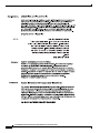
CONTENTS
Preface
CHAPTER
1
vii
Introducing the Cisco Wide Area Virtualization Engine 594 and 694
Supported Products
1-1
1-1
Hardware Features 1-1
Front Panel Components and LEDs 1-2
Back Panel Components and LEDs 1-4
Location of Ports and Connectors 1-5
Connecting a Console Terminal 1-6
Cabling 1-6
Installing the Cisco USB Driver 1-6
CHAPTER
2
Preparing to Install the WAVE-594 and WAVE-694
Safety Warnings and Cautions
2-1
Safety Guidelines 2-2
General Precautions 2-4
System Reliability Considerations 2-5
Protecting Against Electrostatic Discharge
2-5
Understanding the Environmental Requirements
Understanding the Power Requirements
3
Installing the WAVE-594 and WAVE-694
2-5
2-6
Understanding the Grounding Requirements
CHAPTER
2-1
2-6
3-1
Rack-Mounting Considerations, Parts, and Tools
3-1
Rack Mounting and Cabling the WAVE-594 and WAVE-694
Mounting in a 4-Post Rack 3-3
Front-Mounting in a 2-Post Rack 3-5
Cabling 3-7
Connecting Power and Booting the System
Checking the LEDs
3-2
3-8
3-8
Removing or Replacing a WAVE Appliance
3-9
Cisco Wide Area Virtualization Engine 594 and 694 Hardware Installation Guide
OL-24619-02
iii
Contents
CHAPTER
Installing Hardware Options for the WAVE-594 and WAVE-694
4
Installing a Cisco WAVE Interface Module
4-1
Replacing a Hard Disk Drive/Solid State Drive
Replacing a Fan
4-5
Installing Memory 4-6
Removing the Cover 4-6
Installing Memory Modules
WAVE Interface Modules
5
4-2
4-4
Replacing a Power Supply
CHAPTER
4-1
4-7
5-1
Interface Module Descriptions 5-1
Gigabit Ethernet Interface Module—Copper 5-1
Gigabit Ethernet Interface Module—Fiber Optic 5-2
10 Gigabit Ethernet Interface Module—Fiber Optic SFP+
Inline Interface 5-4
Ports and LED Indicators
5-3
5-5
Network Adapter Cabling Requirements 5-8
Gigabit Ethernet—Copper 5-8
Gigabit Ethernet—Fiber Optic 5-10
Installation Scenarios and Cabling Examples for Fast Ethernet Connections
CHAPTER
Troubleshooting the System Hardware
6
Identifying System Problems
6-1
6-1
Checking Connections and Switches
6-2
Troubleshooting the Ethernet Controller 6-2
Network Connection Problems 6-3
Ethernet Controller Troubleshooting Chart
Undetermined Problems
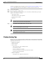
Problem-Solving Tips
Error Symptoms
APPENDIX
A
6-5
6-6
WAVE-594 and WAVE-694 Hardware Specifications
A-1
A-1
Interface Module Specifications
B
6-3
6-4
Appliance Specifications
APPENDIX
5-10
A-3
Maintaining the WAVE-594 and WAVE-694
Maintaining Your Site Environment
B-1
B-1
Cisco Wide Area Virtualization Engine 594 and 694 Hardware Installation Guide
iv
OL-24619-02
Contents
Temperature B-2
Humidity B-2
Altitude B-2
Dust and Particles B-3
Corrosion B-3
Electrostatic Discharge B-3
Electromagnetic and Radio Frequency Interference
Magnetism B-4
Shock and Vibration B-4
Power Source Interruptions B-5
B-4
Using Power Protection Devices B-5
Surge Protectors B-6
Line Conditioners B-6
Uninterruptible Power Supplies B-6
INDEX
Cisco Wide Area Virtualization Engine 594 and 694 Hardware Installation Guide
OL-24619-02
v
Contents
Cisco Wide Area Virtualization Engine 594 and 694 Hardware Installation Guide
vi
OL-24619-02
Preface
This preface describes the purpose of the Cisco Wide Area Virtualization Engine 594 and 694 Hardware
Installation Guide, who should read it, how it is organized, and its document conventions.
This preface contains the following sections:
•
Purpose, page vii
•
Audience, page vii
•
Organization, page viii
•
Conventions, page viii
•
Related Documentation, page xiii
•
Obtaining Documentation and Submitting a Service Request, page xiv
Purpose
This installation guide explains how to prepare your site for installation, how to install a Wide Area
Virtualization Engine 594 and 694 (WAVE-594 and WAVE-694) in an equipment rack, and how to
maintain and troubleshoot the system hardware. After completing the hardware installation procedures
covered in this guide, you will then use the appropriate related publications to configure your system.
(See the “Related Documentation” section on page xiii.)
Audience
To use this installation guide, you should be familiar with internetworking equipment and cabling, and
have a basic knowledge of electronic circuitry and wiring practices.
To complete the installation, including the software configuration for your WAVE-594 and WAVE-694
appliance and for the router that works with the WAVE-594 and WAVE-694 appliance, you should be
familiar with basic networking principles, router configuration, and web page protocols.
Warning
Only trained and qualified personnel should be allowed to install, replace, or service this equipment.
Statement 1030
Cisco Wide Area Virtualization Engine 594 and 694 Hardware Installation Guide
OL-24619-02
vii
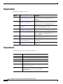
Organization
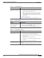
This guide is organized as follows:
Chapter
Title
Description
Chapter 1
Introducing the Cisco Wide Area Describes the physical properties and provides a
Virtualization Engine 594 and
functional overview of the WAVE-594 and
WAVE-694.
694
Chapter 2
Preparing to Install the
WAVE-594 and WAVE-694
Describes safety considerations and gives an
overview of the installation and procedures that you
should perform before the actual installation.
Chapter 3
Installing the WAVE-594 and
WAVE-694
Describes how to install the hardware and connect
the external network interface cables.
Chapter 4
Installing Hardware Options for
the WAVE-594 and WAVE-694
Describes how to install Cisco Interface Modules,
hard disk drives, fans, power supplies, and memory.
Chapter 5
WAVE Interface Modules
Describes the features and cabling requirements of
the Cisco WAVE-594 and WAVE-694 Cisco
Interface Modules.
Chapter 6
Troubleshooting the System
Hardware
Describes troubleshooting procedures for the
hardware installation.
Appendix A WAVE-594 and WAVE-694
Hardware Specifications
Gives a summary of the hardware features and
specifications.
Appendix B Maintaining the WAVE-594 and Describes how to maintain the WAVE-594 and
WAVE-694
WAVE-694.
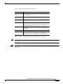
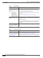
Conventions
Command descriptions use the following conventions:
Convention
Description
boldface font
Commands and keywords are in boldface.
italic font
Variables for which you supply values are in italics.
[ ]
Elements in square brackets are optional.
{x | y | z}
Alternative keywords are grouped in braces and separated
by vertical bars.
[x | y | z]
Optional alternative keywords are grouped in brackets and
separated by vertical bars.
string
A nonquoted set of characters. Do not use quotation marks
around the string, or the string will include the
quotation marks.
Cisco Wide Area Virtualization Engine 594 and 694 Hardware Installation Guide
viii
OL-24619-02
Screen examples use the following conventions:
Convention
screen
font
boldface screen
Description
Terminal sessions and information the system displays are
in screen font.
Information you must enter is in boldface screen font.
font
italic screen
font
Variables for which you supply values are in italic screen
font.
^
The symbol ^ represents the key labeled Control—for
example, the key combination ^D in a screen display means
hold down the Control key while you press the D key.
< >
Nonprinting characters, such as passwords, are in angle
brackets.
[ ]
Default responses to system prompts are in square brackets.
!, #
An exclamation point (!) or a pound sign (#) at the
beginning of a line of code indicates a comment line.
Notes, cautionary statements, and safety warnings use these conventions:
Note
Caution
Means reader take note. Notes contain helpful suggestions or references to materials not contained in
this manual.
Means reader be careful. You are capable of doing something that might result in equipment damage or
loss of data.
Cisco Wide Area Virtualization Engine 594 and 694 Hardware Installation Guide
OL-24619-02
ix
Warning
IMPORTANT SAFETY INSTRUCTIONS
This warning symbol means danger. You are in a situation that could cause
bodily injury. Before you work on any equipment, be aware of the hazards
involved with electrical circuitry and be familiar with standard practices for
preventing accidents. Use the statement number provided at the end of each
warning to locate its translation in the translated safety warnings that
accompanied this device. Statement 1071
SAVE THESE INSTRUCTIONS
Cisco Wide Area Virtualization Engine 594 and 694 Hardware Installation Guide
x
OL-24619-02
Cisco Wide Area Virtualization Engine 594 and 694 Hardware Installation Guide
OL-24619-02
xi
Cisco Wide Area Virtualization Engine 594 and 694 Hardware Installation Guide
xii
OL-24619-02
Related Documentation
The WAVE-594 and WAVE-694 appliance supports the Cisco Wide Area Application Services software
(WAAS) and can function as either a WAAS Central Manager or as an Application Acceleration Engine.
The Cisco WAAS software document set includes the following documents:
•
Release Note for Cisco Wide Area Application Services
•
Cisco Wide Area Application Services Upgrade Guide
•
Cisco Wide Area Application Services Quick Configuration Guide
•
Cisco Wide Area Application Services Configuration Guide
•
Cisco Wide Area Application Services Command Reference
•
Cisco Wide Area Application Services API Reference
•
Cisco Wide Area Application Services Monitoring Guide
•
Cisco WAAS Installation and Configuration Guide for Windows on a Virtual Blade
•
Cisco WAAS Troubleshooting Guide for Release 4.1.3 and Later
Cisco Wide Area Virtualization Engine 594 and 694 Hardware Installation Guide
OL-24619-02
xiii
The documentation for this product also includes the following hardware-related document:
•
Regulatory Compliance and Safety Information for the Cisco Wide Area Virtualization Engines
Obtaining Documentation and Submitting a Service Request
For information on obtaining documentation, submitting a service request, and gathering additional
information, see the monthly What’s New in Cisco Product Documentation, which also lists all new and
revised Cisco technical documentation, at:
http://www.cisco.com/en/US/docs/general/whatsnew/whatsnew.html
Subscribe to the What’s New in Cisco Product Documentation as a Really Simple Syndication (RSS) feed
and set content to be delivered directly to your desktop using a reader application. The RSS feeds are a free
service and Cisco currently supports RSS version 2.0.
Cisco Wide Area Virtualization Engine 594 and 694 Hardware Installation Guide
xiv
OL-24619-02
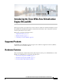
CH A P T E R
1
Introducing the Cisco Wide Area Virtualization
Engine 594 and 694
This chapter provides a basic functional overview of the Cisco Wide Area Virtualization Engine 594 and
694 (WAVE-594 and WAVE-694) appliance and describes the hardware, major components, and front
and back panel indicators and controls.
This chapter contains the following sections:
•
Supported Products, page 1-1
•
Hardware Features, page 1-1
•
Connecting a Console Terminal, page 1-6
Supported Products
The WAVE-594 and WAVE-694 appliance supports Cisco Wide Area Application Services (WAAS)
software version 4.4.1 and later releases.
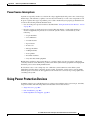
Hardware Features
This section illustrates and describes the front and back panel controls, ports, and LED indicators on the
WAVE-594 and WAVE-694. It contains the following topics:
•
Front Panel Components and LEDs, page 1-2
•
Back Panel Components and LEDs, page 1-4
•
Location of Ports and Connectors, page 1-5
Cisco Wide Area Virtualization Engine 594 and 694 Hardware Installation Guide
OL-24619-02
1-1
Chapter 1
Introducing the Cisco Wide Area Virtualization Engine 594 and 694
Hardware Features
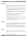
Front Panel Components and LEDs
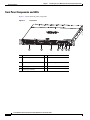
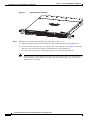
Figure 1-1 shows the front panel components.
Front Panel
246569
Figure 1-1
Cisco Wide Area Virtualization Engine 594
5
1
2
3
4
7
6
1
Interface Module slot
6
10/100/1000 GE 0/0 connector
2
Hard drive bay 1 (device number
0)
7
10/100/1000 GE 0/1 connector
3
Hard drive bay 2 (device number
1)
8
External USB port
4
Console port (mini-USB)
9
Power On button
5
Console port (RJ-45)
8
9
Cisco Wide Area Virtualization Engine 594 and 694 Hardware Installation Guide
1-2
OL-24619-02
Chapter 1
Introducing the Cisco Wide Area Virtualization Engine 594 and 694
Hardware Features
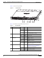
Figure 1-2 shows the front panel LEDs.
Front Panel LEDs
246570
Figure 1-2
Cisco Wide Area Virtualization Engine 594
7
8
1
2
3
4
5
6
9
Table 1-1 describes the front panel LEDs and their functions.
Table 1-1
Front Panel LEDs
LED
1,3
5
6
7
8
9
Drive activity LED
NIC link/activity
NIC speed
System power LED
System fault LED
Storage activity LED
Color
State
Description
Green
Blinking
Drive activity is normal.
Green
On
Online.
Green
Blinking
1Hz
Drive locate.
—
Off
No reading/writing, no activity.
Green
On
Link exists.
Green
Blinking
Activity exists.
—
Off
No link detected.
—
Off
10Mbps connection.
Green
On
100Mbps connection.
Yellow
On
1000Mbps connection.
Green
On
System is on.
—
Off
Power cord is not attached or power supply
failure has occurred.
Yellow
On
System has detected a fault. Refer to the
“Troubleshooting the System Hardware”
chapter for more information.
—
Off
System operation is normal.
Green
Blinking
Drive activity is normal.
Orange
On
Drive failure has occurred.
Cisco Wide Area Virtualization Engine 594 and 694 Hardware Installation Guide
OL-24619-02
1-3
Chapter 1
Introducing the Cisco Wide Area Virtualization Engine 594 and 694
Hardware Features
Back Panel Components and LEDs
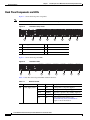
Figure 1-3 shows the back panel components.
Note
To monitor the boot process in normal operation, use a console port.
Figure 1-3
Back Panel Components
1
2
3
4
5
1
Power supply 1
5
Fan 4
2
Power supply 0
6
Fan 3
3
Fan 6
7
Fan 2
4
Fan 5
8
Fan 1
6
7
8
Figure 1-4 shows the back panel LEDs.
Figure 1-4
1
Back Panel LEDs
2
3
4
5
6
7
8
Table 1-2 describes the back panel LEDs and their functions.
Table 1-2
LED
1, 2
Back Panel LEDs
Color
State
Description
Off
No AC power to all power supplies.
Red
Blinking
No AC power to this power supply.
Green
Blinking
AC power is present, only standby output on.
Green
On
Power supply DC outputs on and OK.
Red
On
Power supply failure. Refer to the
“Troubleshooting the System Hardware”
chapter for more information.
Power supply status —
Cisco Wide Area Virtualization Engine 594 and 694 Hardware Installation Guide
1-4
OL-24619-02
Chapter 1
Introducing the Cisco Wide Area Virtualization Engine 594 and 694
Hardware Features
Table 1-2
Back Panel LEDs (continued)
LED
3-8
Fan status
Color
State
Description
Orange
On
Alarm.
Orange
Blinking
Alarm. Fan speed too low.
—
Off
Normal state.
Location of Ports and Connectors
The WAVE appliance supports two Ethernet connectors and two Console ports on the front of the
appliance.
Figure 1-3 shows the back panel ports and connectors.
Warning
To avoid electric shock, do not connect safety extra-low voltage (SELV) circuits to telephone-network
voltage (TNV) circuits. LAN ports contain SELV circuits, and WAN ports contain TNV circuits. Some
LAN and WAN ports both use RJ-45 connectors. Use caution when connecting cables. Statement 1021
This section contains the following topics:
•
Ethernet Port Connectors
•
Console Port Connector
Ethernet Port Connectors
Connect a Category 3, 4, or 5 unshielded twisted-pair cable to an Ethernet connector. 100BASE-TX and
1000BASE-T Fast Ethernet standards require Category 5 or higher cabling.
The WAVE-594 and WAVE-694 appliance has two Ethernet connectors that are attached to the Ethernet
controllers (see Figure 1-5). The Ethernet controllers are integrated on the system board. They provide
an interface for connecting to a 10-Mbps, 100-Mbps, or 1-Gbps network and provide full-duplex (FDX)
capability, which enables simultaneous transmission and reception of data on the network. If the
Ethernet ports in the server support auto negotiation, the controllers detect the data-transfer rate
(10BASE-T, 100BASE-TX, or 1000BASE-T) and duplex mode (full duplex or half duplex) of the
network and automatically operate at that rate and mode. You do not have to set any jumpers or configure
the controllers.
Note
There is a third RJ45 connector on the front of the appliance (see Figure 1-1). This is a console port. Do
not connect this port to your network.
Cisco Wide Area Virtualization Engine 594 and 694 Hardware Installation Guide
OL-24619-02
1-5
Chapter 1
Introducing the Cisco Wide Area Virtualization Engine 594 and 694
Connecting a Console Terminal
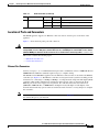
Figure 1-5
Ethernet Port Connector
Speed LED
330210
Link/Activity
LED
8
1
Console Port Connector
The WAVE-594 and WAVE-694 appliance has two console port connectors, serial and mini-USB (see
Figure 1-1). Use a console port connector to access the command-line interface (CLI) for controlling the
WAVE appliance.
For information on connecting a console terminal to the mini-USB console port, see the “Connecting a
Console Terminal” section on page 1-6.
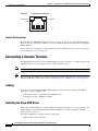
Connecting a Console Terminal
The WAVE appliance has both serial and mini-USB console ports (see Figure 1-1). These ports provide
administrative access to your appliance with a console terminal or PC.
Note
You cannot use both ports at the same time. If both ports are connected, the mini-USB port takes priority.
Note
When using the mini-USB port to connect to a Windows-based PC for the first time, you must install the
Windows USB driver on the PC first. See the “Installing the Cisco USB Driver” section on page 1-6.
Cabling
The following cables included with the WAVE appliance may be used for connecting the WAVE
appliance to a console terminal or PC:
•
USB Console cable—5-pin USB to mini-USB Type A-B
•
Serial Console cable— EIA RJ-45 to DB-9
Installing the Cisco USB Driver
When using the mini-USB port to connect a Microsoft Windows based PC as a console terminal to the
WAVE appliance, you must first install the Windows USB driver on the PC. Otherwise, the USB
interface may not function.
The following Windows operating systems are supported:
•
Windows XP—32-bit and 64-bit
Cisco Wide Area Virtualization Engine 594 and 694 Hardware Installation Guide
1-6
OL-24619-02
Chapter 1
Introducing the Cisco Wide Area Virtualization Engine 594 and 694
Connecting a Console Terminal
•
Vista—32-bit, Business edition
•
Vista—64-bit
•
Windows 7—32-bit and 64-bit
To install the Cisco Microsoft Windows USB driver, perform the following steps:
Note
Do not connect the cable from the Windows PC to the WAVE appliance until after the driver is installed.
Step 1
Load the DVD that came with your WAVE appliance and double-click the CUSBInst.exe file. The Cisco
Virtual Com InstallShield Wizard begins.
You can also access the driver from the WAAS software download area of Cisco.com located at:
http://www.cisco.com/cisco/pub/software/portal/select.html?&mdfid=280484571&catid=268437639&
softwareid=280836712
It’s located under release 4.4.1 and the filename is CUSBInst_Signed_18May2011.exe
Step 2
Click Next. The Ready to Install the Program window appears.
Step 3
Click Install. The InstallShield Wizard Completed window appears.
Step 4
Click Finish.
Step 5
Connect the USB cable to the PC USB port and WAVE appliance mini-USB console port. Within a few
moments, the Found New Hardware Wizard appears.
Follow the instructions to complete the installation of the driver.
Step 6
Note
Once the installation is finished, the USB console is ready for use.
If the driver has been installed on the PC but does not get bound to the hardware, you can manually
browse the driver installation query to the location C:\Windows\tiinst\. The newly attached hardware will
appear in the Windows Device Manager as "TUSB3410 EECode Ser".
This solution also applies when connecting additional WAVE appliances to the same PC. Multiple WAVE
appliances can be independently administered by console sessions on the same PC.
Note
You do not need to reinstall the driver if you change to a different USB port on your PC.
Note
If you happen to install the driver multiple times, each time the driver is installed the virtual COM port
number assigned to the USB port gets incremented. This is expected behavior and may not get reset even
if you uninstall the driver.
Cisco Wide Area Virtualization Engine 594 and 694 Hardware Installation Guide
OL-24619-02
1-7
Chapter 1
Introducing the Cisco Wide Area Virtualization Engine 594 and 694
Connecting a Console Terminal
Cisco Wide Area Virtualization Engine 594 and 694 Hardware Installation Guide
1-8
OL-24619-02
CH A P T E R
2
Preparing to Install the WAVE-594 and WAVE-694
This chapter contains important safety information that you should know before you work with the
WAVE-594 and WAVE-694. Use the guidelines in this chapter to ensure your own personal safety and
to help protect your appliance from potential damage.
This chapter contains the following sections:
Note
•
Safety Warnings and Cautions, page 2-1
•
Safety Guidelines, page 2-2
•
Understanding the Environmental Requirements, page 2-5
•
Understanding the Power Requirements, page 2-6
•
Understanding the Grounding Requirements, page 2-6
Read the Regulatory Compliance and Safety Information for Cisco Wide Area Virtualization Engines
document and the Site Preparation and Safety Guide that came with your appliance before you begin the
installation.
Safety Warnings and Cautions
Before you install the WAVE-594 and WAVE-694, observe the following safety warnings and cautions:
Warning
Read the installation instructions before connecting the system to the power source. Statement 1004
Warning
This unit is intended for installation in restricted access areas. A restricted access area can be
accessed only through the use of a special tool, lock and key, or other means of security.
Statement 1017
Warning
The plug-socket combination must be accessible at all times, because it serves as the main
disconnecting device. Statement 1019
Cisco Wide Area Virtualization Engine 594 and 694 Hardware Installation Guide
OL-24619-02
2-1
Chapter 2
Preparing to Install the WAVE-594 and WAVE-694
Safety Guidelines
Warning
This equipment must be grounded. Never defeat the ground conductor or operate the equipment in the
absence of a suitably installed ground conductor. Contact the appropriate electrical inspection
authority or an electrician if you are uncertain that suitable grounding is available. Statement 1024
Warning
This unit might have more than one power supply connection. All connections must be removed to
de-energize the unit. Statement 1028
Warning
Only trained and qualified personnel should be allowed to install, replace, or service this equipment.
Statement 1030
Warning
This product requires short-circuit (overcurrent) protection, to be provided as part of the building
installation. Install only in accordance with national and local wiring regulations. Statement 1045
Warning
Installation of the equipment must comply with local and national electrical codes. Statement 1074
Caution
To properly ventilate the system, you must provide at least 7.6 cm (3.0 in) of clearance at the front and
back of the WAVE appliance.
Caution
To reduce the risk of electric shock or damage to the equipment:
- Do not disable the power cord grounding plug. The grounding plug is an important safety feature.
- Plug the power cord into a grounded (earthed) electrical outlet that is easily accessible at all times.
- Unplug the power cord from the power supply to disconnect power to the equipment.
- Do not route the power cord where it can be walked on or pinched by items placed against it. Pay
particular attention to the plug, electrical outlet, and the point where the cord extends from the WAVE
appliance.
Caution
To reduce the risk of personal injury or damage to the equipment:
- Observe local occupation health and safety requirements and guidelines for manual handling.
- Obtain adequate assistance to lift and stabilize the chassis during installation or removal. The WAVE
appliance is unstable when not fastened to the rails. When mounting the WAVE appliance in a rack,
remove the power supplies and any other removable module to reduce the overall weight of the product.
Safety Guidelines
To reduce the risk of bodily injury, electrical shock, fire, and damage to the equipment, observe the
precautions in this section.
This section contains the following topics:
•
General Precautions, page 2-4
Cisco Wide Area Virtualization Engine 594 and 694 Hardware Installation Guide
2-2
OL-24619-02
Chapter 2
Preparing to Install the WAVE-594 and WAVE-694
Safety Guidelines
•
System Reliability Considerations, page 2-5
•
Protecting Against Electrostatic Discharge, page 2-5
Cisco Wide Area Virtualization Engine 594 and 694 Hardware Installation Guide
OL-24619-02
2-3
Chapter 2
Preparing to Install the WAVE-594 and WAVE-694
Safety Guidelines
General Precautions
Observe the following general precautions for using and working with the WAVE-594 and WAVE-694:
•
Observe and follow service markings. Do not service any Cisco product except as explained in your
system documentation. Opening or removing covers that are marked with the triangular symbol with
a lightning bolt may expose you to electrical shock. Components inside these compartments should
be serviced only by a trained and qualified service technician.
•
If any of the following conditions occur, unplug the product from the electrical outlet and replace
the part or contact your customer service representative:
– The power cable or plug is damaged.
– An object has fallen into the product.
– The product has been exposed to water.
– The product has been dropped or damaged.
– The product does not operate correctly when you follow the operating instructions.
•
Keep your system components away from radiators and heat sources. Also, do not block cooling
vents.
•
Do not spill food or liquids on your system components, and never operate the product in a wet
environment.
•
Do not push any objects into the openings of your system components. Doing so can cause fire or
electric shock by shorting out interior components.
•
Use the product only with other Cisco-approved equipment.
•
Allow the product to cool before removing covers or touching internal components.
•
Use the correct external power source. Operate the product only from the type of power source
indicated on the electrical ratings label. If you are not sure of the type of power source required,
consult your service representative or local power company.
•
Use only approved power cables. If you have not been provided with a power cable for your WAVE
appliance or for any AC-powered option intended for your system, purchase a power cable that is
approved for use in your country. The power cable must be rated for the product and for the voltage
and current marked on the product’s electrical ratings label. The voltage and current rating of the
cable should be greater than the ratings marked on the product.
•
To help prevent electric shock, plug the system components and peripheral power cables into
properly grounded electrical outlets. These cables are equipped with three-prong plugs to help
ensure proper grounding. Do not use adapter plugs or remove the grounding prong from a cable.
•
Observe power strip ratings. Make sure that the total ampere rating of all products plugged into the
power strip does not exceed 80 percent of the power strip ampere ratings limit.
•
Do not use appliance or voltage converters or kits sold for appliances with your product.
•
To help protect your system components from sudden, transient increases and decreases in electrical
power, use a surge suppressor, line conditioner, or uninterruptible power supply (UPS).
•
Position cables and power cords carefully; route cables and the power cord and plug so that they
cannot be stepped on or tripped over. Be sure that nothing rests on your system components’ cables
or power cord.
•
Do not modify power cables or plugs. Consult a licensed electrician or your power company for site
modifications. Always follow your local or national wiring rules.
Cisco Wide Area Virtualization Engine 594 and 694 Hardware Installation Guide
2-4
OL-24619-02
Chapter 2
Preparing to Install the WAVE-594 and WAVE-694
Understanding the Environmental Requirements
System Reliability Considerations
To help ensure proper cooling and system reliability, make sure that the following occurs:
•
Each of the hard drive bays has either a drive or a filler panel installed.
•
The Interface Module bay has either a Cisco Interface Module or a filler panel installed.
•
Each power supply bay has either a power supply of filler panel installed.
•
For rack configurations, make sure that space is available around the appliance to enable the cooling
system to work properly. See the documentation that comes with the rack for additional information.
•
A removed hot-swappable drive is replaced within 1 minute of removal.
•
Cables for optional adapters are routed according to the instructions provided with the adapters.
•
A failed fan is replaced within 48 hours.
Protecting Against Electrostatic Discharge
Static electricity can harm delicate components inside the appliance. To prevent static damage, discharge
static electricity from your body before you touch any of your system’s electronic components. You can
do so by touching an unpainted metal surface on the chassis.
You can also take the following steps to prevent damage from electrostatic discharge (ESD):
•
When unpacking a static-sensitive component from its shipping carton, do not remove the
component from the antistatic packing material until you are ready to install the component in your
system. Just before unwrapping the antistatic packaging, be sure to discharge static electricity from
your body.
•
When transporting a sensitive component, first place it in an antistatic container or packaging.
•
Handle all sensitive components in a static-safe area. If possible, use antistatic floor pads and
workbench pads.
•
Handle the appliance carefully, holding it by its edges or its frame.
•
Do not touch solder joints, pins, or exposed printed circuitry.
•
Do not leave the appliance where others can handle and possibly damage the appliance.
•
Take additional care when handling appliances during cold weather, because heating reduces indoor
humidity and increases static electricity.
Understanding the Environmental Requirements
To ensure continued safe and reliable equipment operation, install or position the system in a
well-ventilated, climate-controlled environment.
For details about the WAVE-594 and WAVE-694 environmental requirements, see Appendix A,
“WAVE-594 and WAVE-694 Hardware Specifications” and the “Temperature” section on page B-2.
Cisco Wide Area Virtualization Engine 594 and 694 Hardware Installation Guide
OL-24619-02
2-5
Chapter 2
Preparing to Install the WAVE-594 and WAVE-694
Understanding the Power Requirements
Understanding the Power Requirements
Installation of this equipment must comply with local and regional electrical regulations governing the
installation of information technology equipment by licensed electricians. This equipment is designed
to operate in installations covered by NFPA 70, 1999 Edition (National Electric Code) and NFPA-75,
1992 (code for Protection of Electronic Computer/Data Processing Equipment).
Warning
Take care when connecting units to the supply circuit so that wiring is not overloaded. Statement 1018
Caution
Protect the WAVE appliance from power fluctuations and temporary interruptions with a regulating
uninterruptible power supply (UPS). This device protects the hardware from damage caused by power
surges and voltage spikes and keeps the system in operation during a power failure.
When installing more than one WAVE appliance, you may need to use additional power distribution
devices to safely provide power to all devices. Observe the following guidelines:
•
Balance the WAVE appliance power load between available AC supply branch circuits.
•
Do not allow the overall system AC current load to exceed 80 percent of the branch circuit AC
current rating.
•
Do not use common power outlet strips for this equipment.
•
Provide a separate electrical circuit for the WAVE appliance.
For details about the WAVE-594 and WAVE-694 power requirements, see Appendix A, “WAVE-594 and
WAVE-694 Hardware Specifications.”
Understanding the Grounding Requirements
To ensure proper operation and safety, you must properly ground the WAVE appliance. In the United
States, install the equipment in accordance with NFPA 70, 1999 Edition (National Electric Code),
Article 250, as well as any local and regional building codes. In Canada, you must install the equipment
in accordance with Canadian Standards Association, CSA C22.1, Canadian Electrical Code. In all other
countries, you must install the equipment in accordance with any regional or national electrical wiring
codes, such as the International Electrotechnical Commission (IEC) Code 364, parts 1 through 7.
Furthermore, you must be sure that all power distribution devices used in the installation, such as branch
wiring and receptacles, are listed or certified grounding-type devices.
Because of the high ground-leakage currents associated with multiple WAVE appliances connected to
the same power source, we recommend the use of a PDU that is either permanently wired to the
building’s branch circuit or includes a nondetachable cord that is wired to an industrial-style plug.
NEMA locking-style plugs or those complying with IEC 60309 are considered suitable for this purpose.
Using common power outlet strips for the WAVE appliance is not recommended.
Cisco Wide Area Virtualization Engine 594 and 694 Hardware Installation Guide
2-6
OL-24619-02
CH A P T E R
3
Installing the WAVE-594 and WAVE-694
This chapter describes how to install a WAVE-594 and WAVE-694 in an equipment rack. This chapter
contains the following sections:
•
Rack-Mounting Considerations, Parts, and Tools, page 3-1
•
Rack Mounting and Cabling the WAVE-594 and WAVE-694, page 3-2
•
Connecting Power and Booting the System, page 3-8
•
Checking the LEDs, page 3-8
•
Removing or Replacing a WAVE Appliance, page 3-9
Before you begin the installation, read Chapter 2, “Preparing to Install the WAVE-594 and WAVE-694”
and the Regulatory Compliance and Safety Information for Cisco Wide Area Virtualization Engines
document.
Warning
Read the installation instructions before connecting the system to the power source. Statement 1004.
Rack-Mounting Considerations, Parts, and Tools
To allow for servicing and adequate airflow, observe the following space and airflow requirements when
deciding where to install a rack:
•
Leave a minimum clearance of 63.5 cm (25 in) in front of the rack.
•
Leave a minimum clearance of 76.2 cm (30 in) behind the rack.
•
Leave a minimum clearance of 121.9 cm (48 in) from the back of the rack to the back of another
rack or row of racks.
The WAVE-594 and WAVE-694 appliance draws in cool air through the front door and expels warm air
through the rear door. Therefore, the front and rear rack doors must be adequately ventilated to allow
ambient room air to enter the cabinet, and the rear door must be adequately ventilated to allow the warm
air to escape from the cabinet.
Caution
To prevent improper cooling and damage to the equipment, do not block the ventilation openings.
When vertical space in the rack is not filled by a WAVE appliance or rack component, the gaps between
the components cause changes in airflow through the rack and across the WAVE appliances. Cover all
gaps with filler panels to maintain proper airflow.
Cisco Wide Area Virtualization Engine 594 and 694 Hardware Installation Guide
OL-24619-02
3-1
Chapter 3
Installing the WAVE-594 and WAVE-694
Rack Mounting and Cabling the WAVE-594 and WAVE-694
Caution
Always use filler panels to fill empty vertical spaces in the rack. This arrangement ensures proper
airflow. Using a rack without filler panels results in improper cooling that can lead to thermal damage.
Observe the following additional requirements to ensure adequate airflow and to prevent damage to
the equipment:
•
– Front and rear doors—If the 42U rack includes closing front and rear doors, you must allow
5,350 sq cm (830 sq in) of holes evenly distributed from top to bottom to permit adequate
airflow (equivalent to the required 64 percent open area for ventilation).
– Side—The clearance between the installed rack component and the side panels of the rack must
be a minimum of 7 cm (2.75 in).
Note
Rack-mounting the WAVE-594 and WAVE-694 appliance is supported for rear mount in a 4-post rack or
front mount in a 2-post rack.
Table 3-1 lists the rack mounting hardware included in your shipping container. You will need a Phillips
screwdriver. Verify that you have received the following items for the installation:
Table 3-1
Rack Mount Hardware Provided
Rack Type
Item
Name
Description
Qty 2-post
1
Front rack mount
bracket
Front rack mount L bracket
2
2
Rear rack mount
bracket holder
Rear rack mount bracket holder
2
X
3
32” rear rack mount Rear rack mount bracket (32 inch)
bracket
2
X
4
Front rack mount
bracket screw
6
5
Rear rack mount
Rear bracket holder screw, M4 x0.7 x 4.85 mm,
6
bracket holder screw 120º, Flat Head, Phillips, Steel w/ Zinc and Black
6
Rack screw
Rack screw, #10-32 x 0.50”, Truss Head, Phillips, 8
Steel w/ Ni and Black
7
Rack screw
Rack screw, M5 x 12.7 mm, Truss Head, Phillips, 8
Steel w/ Ni and Black
Front rack bracket screw, #6-32 x 0.30”, Wafer
Head, Phillips, Steel w/ Zinc and Black
X
4-post
X
X
X
X
X
X
X
Rack Mounting and Cabling the WAVE-594 and WAVE-694
There are two ways you can rack mount the WAVE appliance. The following topics are included in this
section:
•
Mounting in a 4-Post Rack
•
Front-Mounting in a 2-Post Rack
•
Cabling
Cisco Wide Area Virtualization Engine 594 and 694 Hardware Installation Guide
3-2
OL-24619-02
Chapter 3
Installing the WAVE-594 and WAVE-694
Rack Mounting and Cabling the WAVE-594 and WAVE-694
Warning
To prevent bodily injury when mounting or servicing this unit in a rack, you
must take special precautions to ensure that the system remains stable. The
following guidelines are provided to ensure your safety:
•
This unit should be mounted at the bottom of the rack if it is the only unit in the rack.
•
When mounting this unit in a partially filled rack, load the rack from the bottom to the
top with the heaviest component at the bottom of the rack.
•
If the rack is provided with stabilizing devices, install the stabilizers before mounting
or servicing the unit in the rack. Statement 1006
Mounting in a 4-Post Rack
Follow these steps to mount the WAVE appliance in a 4-post rack:
Step 1
Prepare for installation by reading the “Rack-Mounting Considerations, Parts, and Tools” section on
page 3-1) and verify that you have the correct tools and rack-mount hardware necessary for the
installation.
Step 2
Attach the front rack mount brackets (item #1 in Table 3-1) using the six front bracket screws (item #4
in Table 3-1). (See Figure 3-4.)
Step 3
Attach the rear rack mount holder brackets (item #2 in Table 3-1) using the six rear bracket holder screws
(item #5 in Table 3-1).
Note
The front arrow must point toward the front of the chassis.
Attaching the Brackets
330144
Figure 3-1
Cisco Wide Area Virtualization Engine 594 and 694 Hardware Installation Guide
OL-24619-02
3-3
Chapter 3
Installing the WAVE-594 and WAVE-694
Rack Mounting and Cabling the WAVE-594 and WAVE-694
Step 4
Attach the rear mount bracket holders (item #3 in Table 3-1) to the rear rack posts using four appropriate
rack screws (item #6 or #7 in Table 3-1). (see Figure 3-2)
Attaching Rear Rack Mount to the Rack
330142
Figure 3-2
Step 5
Insert the chassis between the mounting posts and secure (see Figure 3-3):
a.
Insert the chassis into the rack with the rear rack mount holders sliding into the rear rack mount
brackets.
b.
Align the mounting holes in the front brackets with the mounting holes in the equipment rack.
c.
Secure the chassis using four (two on each side) rack screws (item #6 or #7 in Table 3-1) through
the holes in the front brackets and into the threaded holes in the mounting post.
Cisco Wide Area Virtualization Engine 594 and 694 Hardware Installation Guide
3-4
OL-24619-02
Chapter 3
Installing the WAVE-594 and WAVE-694
Rack Mounting and Cabling the WAVE-594 and WAVE-694
Rack-Mounting the Chassis
330145
Figure 3-3
Step 6
Verify that the chassis is securely installed in the rack.
Front-Mounting in a 2-Post Rack
Follow these steps to front-mount the WAVE appliance in a 2-post rack:
Note
There must be an empty 1RU space in the rack directly below the chassis to allow space for the back
edge to sag. A sag of up to 1/2RU (7/8”) is acceptable.
Step 1
Prepare for installation by reading the “Rack-Mounting Considerations, Parts, and Tools” section on
page 3-1) and verify that you have the correct tools and rack-mount hardware necessary for the
installation.
Step 2
Attach the front rack mount brackets (item #1 in Table 3-1) using the six front bracket screws (item #4
in Table 3-1). (See Figure 3-4.)
Cisco Wide Area Virtualization Engine 594 and 694 Hardware Installation Guide
OL-24619-02
3-5
Chapter 3
Installing the WAVE-594 and WAVE-694
Rack Mounting and Cabling the WAVE-594 and WAVE-694
Figure 3-4
Step 3
Attaching the Front Brackets
Insert the chassis between the mounting posts and secure (see Figure 3-5):
a.
Align the mounting holes in the front brackets with the mounting holes in the equipment rack.
b.
Secure the chassis using four (two on each side) rack screws (item #6 or #7 in Table 3-1) through
the holes in the front brackets and into the threaded holes in the mounting post.
c.
Use a tape measure and level to ensure that the chassis is installed straight and level.
Note
Since the chassis is secured in the rack by the front edge only, there must be an empty 1RU space
in the rack directly below the chassis to allow space for the back edge to sag. A sag of up to
1/2RU (7/8”) is acceptable.
Cisco Wide Area Virtualization Engine 594 and 694 Hardware Installation Guide
3-6
OL-24619-02
Chapter 3
Installing the WAVE-594 and WAVE-694
Rack Mounting and Cabling the WAVE-594 and WAVE-694
Figure 3-5
Step 4
Rack-mounting the Chassis
Verify that the chassis is securely installed in the rack.
Cabling
Use the following information (see Figure 3-6) when connecting peripheral cables to the WAVE
appliance.
Warning
To reduce the risk of electric shock, fire, or damage to the equipment, do not plug telephone or
telecommunications connectors into RJ-45 connectors.
Cisco Wide Area Virtualization Engine 594 and 694 Hardware Installation Guide
OL-24619-02
3-7
Chapter 3
Installing the WAVE-594 and WAVE-694
Connecting Power and Booting the System
Figure 3-6
2
3
4
5
330060
1
Cable Connections—Front
1
Console port (mini-USB)
4
10/100/1000 GE 0/1 connector
2
Console port (RJ-45)
5
External USB port
3
10/100/1000 GE 0/0 connector
Connecting Power and Booting the System
To connect power to your system, follow these steps:
Step 1
Review the information in the “Safety Guidelines” section on page 2-2.
Step 2
Plug a power cord into the power cord receptacle on the back of the WAVE appliance.
Step 3
Connect the other end of the power cord to a power source at your installation site.
Step 4
Power up all externally connected devices.
Step 5
Press the power control button on the front of the WAVE appliance.
The system should begin booting. Once the operating system boots, you are ready to initialize the basic
software configuration. (See the software configuration guide for details.)
Note
While the WAVE appliance is powering up, the green power-on LED on the front of the
appliance is on.
Checking the LEDs
When the WAVE-594 and WAVE-694 is up and running, observe the front panel LEDs (see Figure 1-1
and Table 1-1) to verify that your system is operating properly.
To troubleshoot using the LEDs, see Chapter 6, “Troubleshooting the System Hardware.”
Cisco Wide Area Virtualization Engine 594 and 694 Hardware Installation Guide
3-8
OL-24619-02
Chapter 3
Installing the WAVE-594 and WAVE-694
Removing or Replacing a WAVE Appliance
Removing or Replacing a WAVE Appliance
To remove a WAVE appliance from your network, power it down, disconnect the power cords and
network cables, and physically remove the chassis from the rack.
The WAVE appliance is in constant communication with the router on your network. When the router
notices that the WAVE appliance is no longer responding to it, the router stops sending requests to the
WAVE appliance. This action is transparent to users. If other WAVE appliances are attached to the router,
the router continues sending requests to the other WAVE appliances.
When you remove a WAVE appliance, the pages that were cached on that appliance are no longer
available to the router or other WAVE appliances. You might see an increase in outgoing web traffic that
might have otherwise been fulfilled by the WAVE appliance that you are removing. However, after a
time, the router and other WAVE appliances redistribute the load of web traffic.
If you remove the last WAVE appliance from your network, you can also disable WAVE support on the
router. However, this action is not necessary because leaving WAVE support enabled when there are no
WAVE appliances attached has no effect on the router’s performance.
To replace a WAVE appliance, remove it from the network, and then install a new WAVE appliance and
configure it using the same configuration parameters (IP address and so forth) that you used for the
removed WAVE appliance.
Cisco Wide Area Virtualization Engine 594 and 694 Hardware Installation Guide
OL-24619-02
3-9
Chapter 3
Installing the WAVE-594 and WAVE-694
Removing or Replacing a WAVE Appliance
Cisco Wide Area Virtualization Engine 594 and 694 Hardware Installation Guide
3-10
OL-24619-02
CH A P T E R
4
Installing Hardware Options for the WAVE-594
and WAVE-694
This chapter provides basic instructions for installing hardware options in your WAVE-594 and
WAVE-694. These instructions are intended for technicians who are experienced with setting up Cisco
WAVE-594 and WAVE-694 hardware.
This chapter contains the following sections:
•
Installing a Cisco WAVE Interface Module, page 4-1
•
Replacing a Hard Disk Drive/Solid State Drive, page 4-2
•
Replacing a Fan, page 4-4
•
Replacing a Power Supply, page 4-5
•
Installing Memory, page 4-6
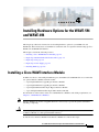
Installing a Cisco WAVE Interface Module
In addition to the two onboard Gigabit Ethernet ports, the WAVE-594 and WAVE-694 can accommodate
one optional Interface Module network module:
•
4-port Gigabit Ethernet Copper Bypass Interface Module
•
8-port Gigabit Ethernet Copper Bypass Interface Module
•
4-port Gigabit Ethernet Fiber Optic Bypass Interface Module
•
2-port 10 Gigabit Ethernet Fiber Optic SPF+ Interface Module
For information on the features of the Cisco WAVE Interface Modules and cabling requirements, see
Chapter 5, “WAVE Interface Modules.”
Note
Caution
Interface Modules are not hot-swappable therefore it is necessary to power the system down before
installing or replacing.
To maintain proper system cooling, do not operate the appliance for more than 1 minute without either
an Interface Module or a filler panel installed in the bay.
To install a Cisco Interface Module in the Interface Module slot, follow these steps:
Cisco Wide Area Virtualization Engine 594 and 694 Hardware Installation Guide
OL-24619-02
4-1
Chapter 4
Installing Hardware Options for the WAVE-594 and WAVE-694
Replacing a Hard Disk Drive/Solid State Drive
Step 1
Review the information in the “Safety Warnings and Cautions” section on page 2-1 and the “Safety
Guidelines” section on page 2-2.
Step 2
Power down the appliance.
Note
Step 3
You must power down the appliance before installing or removing an Interface Module. Interface
Modules are not hot-swappable.
Locate the Interface Module slot in the appliance chassis and slide the Cisco Interface Module into the
slot until the ejector lever is seated.
To remove an Interface Module, first use the ejector lever to unlatch and then pull out the Interface
Module. (See Figure 4-1.)
Interface Module—Removal
246553
Figure 4-1
1
2
Step 4
Power on the appliance.
Step 5
For information about connecting cables to the Cisco WAVE Interface Module ports, see Chapter 5,
“WAVE Interface Modules.”
Replacing a Hard Disk Drive/Solid State Drive
The WAVE appliance supports as many as two 2.5-inch (Small Form Factor) hard drives. The WAVE-594
supports SATA drives and the WAVE-694 supports SAS drives.
Cisco Wide Area Virtualization Engine 594 and 694 Hardware Installation Guide
4-2
OL-24619-02
Chapter 4
Installing Hardware Options for the WAVE-594 and WAVE-694
Replacing a Hard Disk Drive/Solid State Drive
Note
The WAVE-594 supports both Solid State Drives and Hard Disk Drives. You cannot mix HDD and SSD
in the same chasis.
For details about the WAVE-594 appliance specifications, see Appendix A, “Appliance Specifications”.
Hard drives are hot-swappable therefore it is not necessary to power the system down before installing
or replacing.
When removing hard drives from the WAVE appliance, observe the following general guidelines:
Note
Caution
•
The system automatically sets all drive numbers.
•
Drives must be the same capacity to provide the greatest storage space efficiency when drives are
grouped together into the same drive array.
All hard disk drives being used in the appliance must be identical.
To maintain proper system cooling, do not operate the appliance for more than 1 minute without either
a hard disk drive or a filler panel installed in each bay.
To replace a hard disk drive in a bay, follow these steps:
Step 1
Review the information in the “Safety Warnings and Cautions” section on page 2-1 and the “Safety
Guidelines” section on page 2-2.
Step 2
Press the button and swing the handle out. (See Figure 4-2).
Note
Wait 5 seconds before removing to let the disk spin down.
Figure 4-2
Removing a Hard Disk Drive
1
2
Step 3
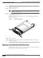
246552
3
After waiting 5 seconds, pull the handle to remove the drive assembly from the bay.
Cisco Wide Area Virtualization Engine 594 and 694 Hardware Installation Guide
OL-24619-02
4-3
Chapter 4
Installing Hardware Options for the WAVE-594 and WAVE-694
Replacing a Fan
Step 4
Within one minute, insert the new drive into the same slot by aligning the replacement drive assembly
with guide rails in the bay and sliding the drive assembly into the bay until it stops. Make sure that the
drive is properly seated in the bay.
Step 5
Close the drive handle.
Step 6
Check the hard disk drive status LED after the system has booted to verify that the hard disk drive is
operating correctly. If the amber hard disk drive status LED for a drive is lit continuously, that drive is
faulty and must be replaced. If the green hard disk drive activity LED is flashing, the drive is being
accessed.
Step 7
Wait 1 minute and then verify that the replaced disk drive is in the Rebuilding state by using the show
disks details command in EXEC mode.
Note
The system automatically starts the rebuild operation when it detects the removal and reinsertion
of a drive that is part of the logical RAID drive.
Step 8
Wait until the rebuild operation is complete. A disk rebuild operation may take several hours. You can
check if the rebuild operation is complete by using the show disk details command in EXEC mode. The
physical drive state will be Online and the RAID logical drive state will be Okay after the rebuild
operation is completed.
Step 9
Use the show disk tech command in EXEC mode to verify that the firmware and BIOS information is
correct for both hard drives.
If you have multiple disk failures and your RAID-1 logical status is Offline, you must recreate the
RAID-1 array. For more information on disk removal and replacement procedures, see the Cisco Wide
Area Application Services Configuration Guide chapter named “Maintaining Your WAAS System.”
Replacing a Fan
The WAVE appliance supports six fan assemblies that are hot-swappable.
Fan assemblies can only be inserted in one orientation.
Note
Caution
Fan assemblies must be inserted and can only function with the surface marked “TOP” facing up.
To maintain proper system cooling, do not operate the appliance for more than 1 minute without a fan
installed in each bay.
To replace a fan assembly, follow these steps:
Step 1
Review the information in the “Safety Warnings and Cautions” section on page 2-1 and the “Safety
Guidelines” section on page 2-2.
Step 2
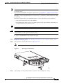
Disengage the fan latch and pull the fan out by the handle (see Figure 4-3).
Cisco Wide Area Virtualization Engine 594 and 694 Hardware Installation Guide
4-4
OL-24619-02
Chapter 4
Installing Hardware Options for the WAVE-594 and WAVE-694
Replacing a Power Supply
Figure 4-3
Fan Assembly
1
246554
2
Step 3
Within one minute, insert the new fan with the surface marked “TOP” facing up and verify that the latch
is engaged.
Step 4
Check the power LED to verify that the new fan is receiving power.
Note
If a fan alarm occurs and you power down the WAVE appliance to replace the fan, you must use the clear
bmc event-log global configuration command and then reboot to clear the alarm.
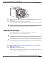
Replacing a Power Supply
The WAVE appliance supports two power supply assemblies that are hot-swap capable.
Power supply assemblies can only be inserted in one orientation.
Note
Power supply assemblies must be inserted and can only function with the surface marked “TOP” facing
up.
Caution
To maintain proper system cooling, do not operate the appliance for more than 1 minute without either
a power supply or a filler panel installed in each bay.
To replace a power supply assembly, follow these steps:
Step 1
Review the information in the “Safety Warnings and Cautions” section on page 2-1 and the “Safety
Guidelines” section on page 2-2.
Step 2
Remove the power cord from the power supply.
Note
When more than one power supply assembly is present, load-sharing is supported. If one loses
power, the second power supply takes over.
Cisco Wide Area Virtualization Engine 594 and 694 Hardware Installation Guide
OL-24619-02
4-5
Chapter 4
Installing Hardware Options for the WAVE-594 and WAVE-694
Installing Memory
Step 3
Disengage the latch and pull the power supply out by the handle. (See Figure 4-4.)
Power Supply Assembly
246692
Figure 4-4
Step 4
Within one minute, insert the new power supply with the surface marked “TOP” facing up and verify
that the latch is engaged.
Step 5
Insert the power cord into the replacement power supply.
Step 6
Check the power LED to verify that the new power supply is receiving power.
Note
If a power supply alarm occurs and you power down the WAVE appliance to replace the power supply,
you must use the clear bmc event-log global configuration command and then reboot to clear the alarm.
Installing Memory
This section provides basic instructions for installing memory in your WAVE-594 and WAVE-694. It
contains the following topics:
•
Removing the Cover, page 4-6
•
Installing Memory Modules, page 4-7
Removing the Cover
Warning
Caution
Before working on a system that has an on/off switch, turn OFF the power and unplug the power cord.
Statement 1
To reduce the risk of personal injury from hot surfaces, allow the drives and the internal system
components to cool before touching them.
Cisco Wide Area Virtualization Engine 594 and 694 Hardware Installation Guide
4-6
OL-24619-02
Chapter 4
Installing Hardware Options for the WAVE-594 and WAVE-694
Installing Memory
Caution
Do not operate the WAVE appliance with the access panel open or removed. Operating the WAVE
appliance in this manner results in improper airflow and improper cooling that can lead to thermal
damage.
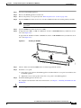
To remove the appliance cover, follow these steps:
Step 1
Review the information in the “Safety Warnings and Cautions” section on page 2-1 and the “Safety
Guidelines” section on page 2-2.
Step 2
Power off the appliance and all attached devices and disconnect all external cables and power cords.
Step 3
Remove the WAVE appliance from the rack.
Step 4
Loosen the screw on the top that secures the access panel to the WAVE appliance.
Step 5
Slide the access panel toward the front of the WAVE appliance, then lift it from the WAVE appliance.
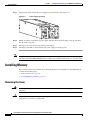
Installing Memory Modules
The WAVE-594 appliance supports either 8 GB or 12 GB of memory using 2-GB RDIMM memory
modules. The WAVE-694 appliance supports either 16 GB or 24 GB of memory using 4-GB RDIMM
memory modules.
Observe the following guidelines when installing additional memory:
•
Use only Cisco memory upgrades in your appliance.
•
BIOS detects the DIMM population and sets the system to dual-bank interleaved mode (DIMMs
installed in both banks with equal bank capacities).
Figure 4-5 shows the memory slot mapping on the system board.
Cisco Wide Area Virtualization Engine 594 and 694 Hardware Installation Guide
OL-24619-02
4-7
Chapter 4
Installing Hardware Options for the WAVE-594 and WAVE-694
Installing Memory
Figure 4-5
Memory Slot Mapping
330139
A3 A2 A1 B3 B2 B1
Table 4-1 and Table 4-2 list the RDIMM configurations available for the WAVE-594 and WAVE-694
appliance.
Table 4-1
WAVE-594 RDIMM Configurations
Slot A3
Slot A2
Slot A1
Slot B3
Slot B2
Slot B1
8 GB Memory
—
2-GB
2-GB
—
2-GB
2-GB
12 GB Memory
2-GB
2-GB
2-GB
2-GB
2-GB
2-GB
Table 4-2
WAVE-694 RDIMM Configurations
Slot A3
Slot A2
Slot A1
Slot B3
Slot B2
Slot B1
16 GB Memory
—
4-GB
4-GB
—
4-GB
4-GB
24 GB Memory
4-GB
4-GB
4-GB
4-GB
4-GB
4-GB
To install a Cisco memory upgrade on the WAVE-594 from 8 GB to 12 GB or on the WAVE-694 from
16 GB to 24 GB, follow these steps:
Cisco Wide Area Virtualization Engine 594 and 694 Hardware Installation Guide
4-8
OL-24619-02
Chapter 4
Installing Hardware Options for the WAVE-594 and WAVE-694
Installing Memory
Step 1
Power down the WAVE appliance.
Step 2
Remove the WAVE appliance from the rack.
Step 3
Remove the primary access panel (See the “Removing the Cover” section on page 4-6).
Step 4
Open the DIMM slot latches for slots A1, A2, B1, and B2 and remove the existing memory modules.
Note
All existing memory must be removed and replaced by the RDIMMS contained in the Cisco
upgrade kit.
Step 5
Open the DIMM slot latches for slots A3 and B3.
Step 6
To upgrade from 8 GB to 12 GB on a WAVE-594, install a 2-GB RDIMM memory module into all six
slots. (See Figure 4-6.)
To upgrade from 16 GB to 24 GB on a WAVE-694, install a 4-GB RDIMM memory module into all six
slots. (See Figure 4-6.)
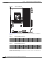
Figure 4-6
Installing an RDIMM
2
2
330140
1
Step 7
Check to make sure that the DIMM latches are fully engaged in the notches.
Step 8
Install the access panel.
Step 9
a.
Lower the access panel onto the WAVE appliance and then slide the access panel toward the back of
the WAVE appliance.
b.
Tighten the screw on the top that secures the access panel to the WAVE appliance.
Install the WAVE appliance into the rack.
For complete rack installation and removal instructions, see Chapter 3, “Installing the WAVE-594 and
WAVE-694.”
Caution
Install the appliance only in a rack cabinet with perforated doors.
Cisco Wide Area Virtualization Engine 594 and 694 Hardware Installation Guide
OL-24619-02
4-9
Chapter 4
Installing Hardware Options for the WAVE-594 and WAVE-694
Installing Memory
Caution
Do not leave open spaces above or below an installed appliance in the rack cabinet. To help prevent
damage to appliance components, always install a filler panel to cover the open space and to help ensure
proper air circulation. See the documentation that comes with your rack cabinet for more information.
Step 10
Connect the cables and power cords. For information on connecting cables and power cords, see the
“Rack Mounting and Cabling the WAVE-594 and WAVE-694” section on page 3-2.
Step 11
Reboot the WAVE appliance.
Step 12
Use the show memory EXEC mode command to verify that the memory you installed is recognized by
the WAVE appliance.
Step 13
Repartition the disks, using the disk delete-data-partitions command, and reload.
Note
Repartitioning the disks deletes all data, including all virtual blades on the hardware.
Note
Repartitioning the disks is required after adding memory to reset the DRE space allocation.
Cisco Wide Area Virtualization Engine 594 and 694 Hardware Installation Guide
4-10
OL-24619-02
CH A P T E R
5
WAVE Interface Modules
This chapter describes Cisco WAVE Interface Modules and contains the following sections:
•
Interface Module Descriptions, page 5-1
•
Ports and LED Indicators, page 5-5
•
Network Adapter Cabling Requirements, page 5-8
•
Installation Scenarios and Cabling Examples for Fast Ethernet Connections, page 5-10
For information on installing an inline adapter in your WAVE-594 and WAVE-694, see the “Installing a
Cisco WAVE Interface Module” section on page 4-1.
For adapter specifications, see Table A-2 in Appendix A.
Interface Module Descriptions
The WAVE appliance supports one optional 4-port Copper Gigabit Ethernet Interface Module, 8-port
Copper Gigabit Ethernet Interface Module, 4-port Fiber Optic Gigabit Ethernet Interface Module, or
2-port SFP+ Fiber Optic 10 Gigabit Ethernet Interface Module.
This section contains the following topics:
•
Gigabit Ethernet Interface Module—Copper
•
Gigabit Ethernet Interface Module—Fiber Optic
•
10 Gigabit Ethernet Interface Module—Fiber Optic SFP+
•
Inline Interface
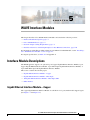
Gigabit Ethernet Interface Module—Copper
The copper Gigabit Ethernet Interface Module is available in 4 or 8 ports. Both models support bypass.
(See Figure 5-1 and Figure 5-2.)
Cisco Wide Area Virtualization Engine 594 and 694 Hardware Installation Guide
OL-24619-02
5-1
Chapter 5
WAVE Interface Modules
Interface Module Descriptions
Gigabit Ethernet Interface Module—4-Port Copper
Figure 5-2
Gigabit Ethernet Interface Module—8-Port Copper
246687
246685
Figure 5-1
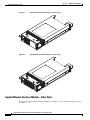
Gigabit Ethernet Interface Module—Fiber Optic
The fiber optic Gigabit Ethernet Interface Module is available in 4 ports. This model supports bypass.
(See Figure 5-3.)
Cisco Wide Area Virtualization Engine 594 and 694 Hardware Installation Guide
5-2
OL-24619-02
Chapter 5
WAVE Interface Modules
Interface Module Descriptions
Gigabit Ethernet Interface Module—4-Port Fiber Optic
246686
Figure 5-3
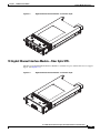
10 Gigabit Ethernet Interface Module—Fiber Optic SFP+
The fiber optic Gigabit Ethernet Interface Module is available in 2 ports. This model does not support
bypass. (See Figure 5-4.)
Gigabit Ethernet Interface Module—2-Port Fiber Optic
246684
Figure 5-4
Cisco Wide Area Virtualization Engine 594 and 694 Hardware Installation Guide
OL-24619-02
5-3
Chapter 5
WAVE Interface Modules
Interface Module Descriptions
Inline Interface
When you configure the WAVE appliance for inline interception mode, you can set attributes to control
which interfaces are to be used over which VLANs. By default, the module operates on all inline-capable
interfaces and VLANs. You can configure the inline redirection feature using the WAAS CLI or the
WAAS Central Manager GUI.
Note
Throughout this section, we refer to a WAVE appliance configured for inline interception mode as a
WAVE inline appliance.
The WAAS software defines two interface types: A group interface that represents an inline pair
grouping and a port interface that represents the individual port. These interfaces are referred to as
inlineGroup and inlinePort.
InlineGroup interfaces are numbered using the format slot/group. The slot number is the slot in which
the adapter is inserted. Since there is only one slot, the slot number is always 1.
The group number starts from 0 and can go up to 4 on 8-port Interface Modules. For 4-port Interface
Modules, the groups are numbered 0 and 1. Groups are numbered from left to right.
InlinePort interfaces are numbered slot/group/lan or slot/group/wan. The last attribute is the LAN or
WAN designator.
For copper Interface Modules, the top row consists of WAN ports and the bottom row consists of LAN
ports. For fiber Interface Modules, the ports are designated as WAN and LAN form left to right. For
example, the four ports on the 4-port fiber Interface Module are designated as “W0 L0 W1 L1” in inline
mode:
•
W0—InlineGroup 1/0/WAN
•
L0—InlineGroup 1/0/LAN
•
W1—InlineGroup 1/1/WAN
•
L1—InlineGroup 1/1/LAN
The inline network adapter also includes an onboard programmable watch dog timer (WDT) controller
that allows you to set the time to wait after a failure event, such as a power outage or a kernel crash,
before the unit begins to operate in mechanical bypass mode. This can be configured using the inline
failover timeout global configuration command:
(config)# inline failover timeout ?
<1-1> 1 second
<25-25> 25 seconds
<5-5> 5 seconds
In mechanical bypass mode, the traffic is bridged between the LAN and WAN ports of each group.
Mechanical bypass mode prevents the WAVE appliance from becoming a single point of failure and
allows traffic to continue to flow between the router and the client while it passes through an
unresponsive WAVE appliance without being processed.
For more information about configuring the inline network adapter, see the Cisco Wide Area Application
Services Configuration Guide.
Cisco Wide Area Virtualization Engine 594 and 694 Hardware Installation Guide
5-4
OL-24619-02
Chapter 5
WAVE Interface Modules
Ports and LED Indicators
Ports and LED Indicators
Figure 5-5 shows the 4-port Copper Gigabit Ethernet Interface Module port numbers, interface
designations, and LEDs. Figure 5-6 shows the same information for the 8-port adapter.
Figure 5-5
4-Port Copper Gigabit Ethernet Interface Module—Port Numbering and LEDs
4 PORT BYPASS
0
1
2
1
GE 0/1
246548
3
Status
GE 2/3
2
Figure 5-6
8-Port Copper Gigabit Ethernet Interface Module—Port Numbering and LEDs
0
0
1
1
2
2
3
3
Status
1
GE 0/1
GE 2/3
GE 4/5
GE 6/7
2
Status
246548
8 Port GE
Copper Inline
2
The Interface Module has an LED that corresponds to each port. Table 5-1 describes the LEDs.
Table 5-1
Copper Interface Module—Power and Status LEDs
LED
Name
Color
State
Description
1
Interface Module
power LED
Green
On
Interface Module is receiving power.
—
Off
Interface Module is not installed or a power
supply failure has occurred.
Bypass status
Green
Normal
Indicates the inline port pair is in interception
mode.
Amber
Bypass
Indicates the inline port pair is in bypass
mode.
—
Off
No activity exists.
2
Figure 5-7 shows the Gigabit Ethernet ports and LEDs for the 4-port and 8-port Copper Interface
Module.
Cisco Wide Area Virtualization Engine 594 and 694 Hardware Installation Guide
OL-24619-02
5-5
Chapter 5
WAVE Interface Modules
Ports and LED Indicators
Figure 5-7
Copper Interface Module—Gigabit Ethernet LEDs
Speed LED
330210
Link/Activity
LED
8
1
Table 5-2 describes the Gigabit Ethernet port LEDs.
Table 5-2
Copper Interface Module—Gigabit Ethernet LEDs
Name
Color
State
Description
NIC link/activity
Green
On
Link exists.
Green
Blinking
Activity exists.
—
Off
No link detected.
—
Off
10Mbps connection.
Green
On
100Mbps connection.
Yellow
On
1000Mbps connection.
NIC speed
Figure 5-8 shows the 4-port Fiber Optic Gibabit Ethernet Interface Module port numbers, interface
designations, and LEDs.
4-Port Fiber Optic Gigabit Ethernet Interface Module—Port Numbering and LEDs
GE 0
A Status
GE 1
GE 2
GE 3
A Status
A Status
A Status
4 Port GE SX Inline
1
246550
Figure 5-8
2 3
The Interface Module has an LED that corresponds to each port. Table 5-3 describes the LEDs.
Table 5-3
Fiber Optic Interface Module—Power and Status LEDs
LED
Name
Color
State
Description
1
Interface Module
power LED
Green
On
Interface Module is receiving power.
—
Off
Interface Module is not installed or a power
supply failure has occurred.
Cisco Wide Area Virtualization Engine 594 and 694 Hardware Installation Guide
5-6
OL-24619-02
Chapter 5
WAVE Interface Modules
Ports and LED Indicators
Table 5-3
2
Fiber Optic Interface Module—Power and Status LEDs
Activity
3
Bypass status
Green
On
Link exists.
Green
Blinking
Transmitting.
—
Off
No link detected.
Green
Normal
Indicates the inline port pair is in interception
mode.
Amber
Bypass
Indicates the inline port pair is in bypass
mode.
Figure 5-9 shows the 2-port Fiber Optic 10 Gibabit Ethernet SFP+ Interface Module port numbers,
interface designations, and LEDs.
Figure 5-9
2-Port Fiber Optic 10 Gigabit Ethernet SFP+ Interface Module—Port Numbering and
LEDs
2 3
2 Port 10GE SFP+
S
A
10GE 1
10GE 0
1
Note
S
246551
A
4
The 2-Port Fiber Optic 10 Gigabit Ethernet SFP+ Interface Module does not support mechanical bypass.
The Interface Module has an LED that corresponds to each port. Table 5-4 describes the LEDs.
Table 5-4
Inline Network Adapter LEDs
LED
Name
Color
State
Description
1
Interface Module
Power LED
Green
On
Interface Module is receiving power.
—
Off
Interface Module is not installed or a power
supply failure has occurred.
Activity
—
Off
No link is detected.
Green
On
Link is detected.
Green
Blinking
Transmitting.
Yellow
On
Interface Module is administratively shut
down.
2
Cisco Wide Area Virtualization Engine 594 and 694 Hardware Installation Guide
OL-24619-02
5-7
Chapter 5
WAVE Interface Modules
Network Adapter Cabling Requirements
Table 5-4
Inline Network Adapter LEDs (continued)
LED
Name
Color
State
Description
3
Speed
—
Off
No link is detected.
Green
On
10 Gigabit Ethernet connection.
Yellow
On
1 Gigabit Ethernet connection.
Network Adapter Cabling Requirements
Gigabit Ethernet—Copper
The Interface Module ships with two types of cables: crossover and straight-through. When you connect
the WAVE inline network adapter, the cable that you use depends on the link speed (Gigabit Ethernet or
Fast Ethernet) and the types of devices (DCE or DTE) being connected.
Note
You must retain the same link speed from one end of the connection to the other end. Inline adapter
interfaces are able to autonegotiate link speeds. If you configure any of your connecting interfaces for
Fast Ethernet (whether on a switch or a router), your WAVE inline adapter uses Fast Ethernet. If you
configure any of your connecting interfaces for Gigabit Ethernet, your WAVE inline adapter uses Gigabit
Ethernet. Speed and duplex settings are port specific so that two inline ports can negotiate different
speeds independently.
If you are connecting a WAVE inline appliance between two devices using Gigabit Ethernet, you can use
either straight-through cables, crossover cables, or any combination of the two cable types, regardless of
the type of device. However, for consistency, we recommend that you use straight-through cables for all
Gigabit Ethernet connections.
Table 5-5 shows the cable requirements for WAVE appliance and non-WAVE appliance connections
when you are using Gigabit Ethernet end to end.
Table 5-5
Cable Requirements for WAVE Connections Using Gigabit Ethernet
Connection
Required Cable
Switch to switch (no WAVE)
Crossover or straight-through
Switch to router (no WAVE)
Crossover or straight-through
Router to router (no WAVE)
Crossover or straight-through
Switch to WAVE and
Crossover or straight-through
WAVE to Router
Crossover or straight-through
Switch to WAVE and
Crossover or straight-through
WAVE to Switch
Crossover or straight-through
Router to WAVE and
Crossover or straight-through
WAVE to Router
Crossover or straight-through
WAVE to WAVE
Crossover or straight-through
Cisco Wide Area Virtualization Engine 594 and 694 Hardware Installation Guide
5-8
OL-24619-02
Chapter 5
WAVE Interface Modules
Network Adapter Cabling Requirements
Some switches support automatic medium-dependent interface crossover (MDIX). You can configure
MDIX by using the mdix auto global configuration switch command. If your switch supports MDIX,
you do not need to follow these cabling rules because MDIX automatically adjusts transmit and receive
pairs when an incorrect cable type (crossover or straight-through) is installed on a 10/100 Fast Ethernet
port. However, when you configure MDIX, you must also configure the port to use autosense (not
manual selection of speed/duplex).
Caution
If you are connecting to Fast Ethernet ports on both the LAN and the WAN sides of the WAVE inline
appliance, you must consider the types of devices that are being connected, and you must use the correct
cables. You must follow these cabling instructions for the inline network adapter to work properly. (See
Table 5-6. For illustrations and examples, see the “Installation Scenarios and Cabling Examples for Fast
Ethernet Connections” section on page 5-10.)
To connect the inline network adapter using the correct cables for Fast Ethernet connections, follow
these steps:
Step 1
Determine the type of cable that you would use for a direct connection between your two end devices
(without a WAVE inline network appliance connected between them) by using the following standard
cabling rules:
•
When you are directly connecting two network devices that are similar, such as two switches, use a
crossover cable.
•
When you are directly connecting two network devices that are different, such as a switch and router,
use a straight-through cable.
Note
Because the inline network adapter has an internal crossover connection that becomes active
when the InlineGroup interface is placed in mechanical bypass mode, you must decide which
cable you would use to connect the two network devices directly, and then you must install the
other cable type (on one side, usually the WAN side of the inline appliance) instead.
Table 5-6 shows the cable requirements for WAVE and non-WAVE connections when you are using Fast
Ethernet end to end.
Table 5-6
Cable Requirements for WAVE Connections Using Fast Ethernet
Connection
Required Cable
Switch to switch (no WAVE)
Crossover
Switch to router (no WAVE)
Straight-through
Router to router (no WAVE)
Crossover
Switch to WAVE and
Straight-through
WAVE to Router
Crossover
Switch to WAVE and
Straight-through
WAVE to Switch
Straight-through
Router to WAVE and
Straight-through
WAVE to Router
Straight-through
WAVE to WAVE
Crossover
Cisco Wide Area Virtualization Engine 594 and 694 Hardware Installation Guide
OL-24619-02
5-9
Chapter 5
WAVE Interface Modules
Installation Scenarios and Cabling Examples for Fast Ethernet Connections
Step 2
Connect Fast Ethernet ports on both the LAN and the WAN sides of the WAVE inline appliance by using
the following cable types:
•
On the LAN side of the connection, use a straight-through cable between the WAVE inline appliance
and the network device.
•
On the WAN side of the connection, use the cable that is different from the cable that you would use
to connect the two network devices directly (as determined in Step 1).
For example, if you are connecting a router and a switch (two different devices) through the WAVE
inline appliance, use a straight-through cable on the LAN side of the connection and use a crossover
cable on the WAN side of the connection. (If you were connecting the two different devices directly,
you would use a straight-through cable, so use the crossover cable instead.)
If you are connecting two switches (or two similar devices), use straight-through cables on both the
LAN and the WAN sides of the WAVE inline appliance.
Figure 5-10 through Figure 5-12 show which cables to use for the WAVE LAN and WAN
connections between Fast Ethernet ports.
Gigabit Ethernet—Fiber Optic
The following three SFP+ pluggable transceiver modules are supported for use with the 2-port Fiber
Optic 10 Gigabit Ethernet Interface Module:
•
SFP-10G-SR—Short range fiber xcvr
•
SFP-H10G-CU3M— Three meter captive copper cable with xcvrs
•
SFP-H10G-CU5M— Five meter captive copper cable with xcvrs
Transceivers not supported will be rejected by the software.
For fiber cable length reach and IEEE standards for the supported transceivers, refer to the pluggable
10G optics data sheet on Cisco.com:
http://www.cisco.com/en/US/prod/collateral/modules/ps5455/data_sheet_c78-455693.html
Optical reach is 137 m (449 ft) to any individual port. This allows for a total of 274 m (899 ft) when
operating in bypass mode.
Installation Scenarios and Cabling Examples for Fast Ethernet
Connections
WAVE appliances can be installed physically between two network devices (such as the branch office
router and branch office LAN switch) by connecting the WAVE inline network adapter ports to the
network devices using the proper cables.
If you are connecting a WAVE inline appliance between two devices using Gigabit Ethernet, you can use
either straight-through cables, crossover cables, or any combination of the two cable types, regardless of
the type of device. This section shows cabling examples for Fast Ethernet connections only, because Fast
Ethernet has specific cabling requirements.
The inline network adapter has four ports that are divided into two inline groups (see the “Ports and LED
Indicators” section on page 5-5). The WAVE appliance can be physically placed inline between two
distinct network paths, creating redundant WAN links. (See Figure 5-10.)
Cisco Wide Area Virtualization Engine 594 and 694 Hardware Installation Guide
5-10
OL-24619-02
Chapter 5
WAVE Interface Modules
Installation Scenarios and Cabling Examples for Fast Ethernet Connections
Two WAVE appliances with inline network adapters can also be installed back-to-back in a serial fashion
between two network devices for failover purposes. In this serial cluster configuration, if one WAVE
appliance fails, the other WAVE appliance can provide optimization. (See Figure 5-11.)
Note
When you connect two WAVE inline appliances to each other serially, always use a crossover cable
between the two WAVE appliances. (See Figure 5-12.)
Figure 5-10
Cabling for a Single Inline WAVE Appliance with Redundant WAN Connections
1
MGMT
WAN
4
2
Router A
WAVE
5
WAN
Router B
1
Connection: Management
2
243288
3
LAN switch
Gigabit Ethernet: 1/0
Connection: WAVE to LAN switch
(using InlineGroup 1/0)
Cable type: Straight-through (recommended)
Fast Ethernet: LAN0 (InlinePort 1/0/lan)
Cable type: Straight-through
3
5
Connection: WAVE to LAN switch
(using InlineGroup 1/1)
4
Connection: WAVE to WAN router A
(using InlineGroup 1/0)
Fast Ethernet: LAN1 (InlinePort 1/1/lan)
Fast Ethernet: WAN0 (InlinePort 1/0/wan)
Cable type: Straight-through
Cable type: Crossover
Connection: WAVE to WAN router B
(using InlineGroup 1/1)
Fast Ethernet: WAN1 (InlinePort 1/1/wan)
Cable type: Crossover
Cisco Wide Area Virtualization Engine 594 and 694 Hardware Installation Guide
OL-24619-02
5-11
Chapter 5
WAVE Interface Modules
Installation Scenarios and Cabling Examples for Fast Ethernet Connections
Figure 5-11
Cabling for Serial Cluster Inline WAVEs with a Single WAN Connection
MGMT
LAN switch
1
1
2
3
WAVE1
Router B
WAVE2
2
Connection: WAVE 1 to LAN switch
Fast Ethernet: LAN0 (InlinePort 1/0/lan)
243289
WAN
Connection: WAVE 1 to WAVE 2
Fast Ethernet: WAVE1 WAN0
(InlinePort 1/0/wan) to WAVE 2 LAN0
(InlinePort 1/0/lan)
Cable type: Straight-through
Cable type: Crossover
3
Connection: WAVE 2 to WAN router
Fast Ethernet: WAVE 2 WAN0
(InlinePort 1/0/wan)
Cable type: Crossover
Figure 5-12
Cabling Between Two Inline WAVEs
WAN
3
WAVE2
inline ada
Router
0
1
2
3
BYPASS
LINK/ACT
100
1000
2
WAVE1
inline adapter
1
0
1
LAN switch
3
BYPASS
LINK/ACT
100
1000
243290
2
Cisco Wide Area Virtualization Engine 594 and 694 Hardware Installation Guide
5-12
OL-24619-02
Chapter 5
WAVE Interface Modules
Installation Scenarios and Cabling Examples for Fast Ethernet Connections
1
Connection: WAVE 1 to LAN switch
Fast Ethernet: WAVE 1 LAN0
(InlinePort 1/0/lan)
Cable type: Straight-through
2
Connection: WAVE 1 to WAVE 2
Fast Ethernet: WAVE 1 WAN0
(InlinePort 1/0/wan) to WAVE 2 LAN0
(InlinePort 1/0/lan)
Cable type: Crossover
3
Connection: WAVE 2 to WAN router
Fast Ethernet: WAVE 2 WAN0
(InlinePort 1/0/wan)
Cable type: Crossover
Cisco Wide Area Virtualization Engine 594 and 694 Hardware Installation Guide
OL-24619-02
5-13
Chapter 5
WAVE Interface Modules
Installation Scenarios and Cabling Examples for Fast Ethernet Connections
Cisco Wide Area Virtualization Engine 594 and 694 Hardware Installation Guide
5-14
OL-24619-02
CH A P T E R
6
Troubleshooting the System Hardware
This chapter provides basic troubleshooting information to help you identify some common problems
that might occur with your WAVE-594 and WAVE-694.
This chapter contains the following sections:
•
Identifying System Problems, page 6-1
•
Checking Connections and Switches, page 6-2
•
Troubleshooting the Ethernet Controller, page 6-2
•
Undetermined Problems, page 6-4
•
Problem-Solving Tips, page 6-5
•
Error Symptoms, page 6-6
Use the information in this chapter to determine whether a problem originates with the hardware or the
software. For further assistance, contact your Cisco customer service representative.
Note
When console redirection is enabled (it is disabled by default), all the tests available from a keyboard
are accessible through the console connection as well. (Mouse support, however, is not available through
the console connection.)
Caution
Customer-replaceable components include the WAVE Interface Modules, hard disk drives, power supply
assemblies, fans, and memory. All other components that are not orderable as spare hardware options
can only be replaced by a qualified service technician. Once you have identified a faulty component,
contact the Cisco Technical Assistance Center (TAC).
Identifying System Problems
To identify system problems, follow these steps:
Step 1
Check the power LED.
Step 2
Check the system fault LED (see System fault LED, page 1-3). If the status is yellow, check for alarms
using the show alarms command.
Step 3
Power down the appliance and all external devices.
Step 4
Check all cables and power cords. (See the “Checking Connections and Switches” section on page 6-2.)
Cisco Wide Area Virtualization Engine 594 and 694 Hardware Installation Guide
OL-24619-02
6-1
Chapter 6
Troubleshooting the System Hardware
Checking Connections and Switches
Step 5
Power up the appliance.
Step 6
If the self-diagnostic programs were completed successfully and you still suspect a problem, see the
“Undetermined Problems” section on page 6-4.
Step 7
Check the system error log to see if an error was recorded by the system.
Checking Connections and Switches
Improperly set switches and controls and loose or improperly connected cables are the most likely source
of problems for the chassis or other external equipment. A quick check of all the switches, controls, and
cable connections can easily solve these problems. (See Figure 1-1 for the location of front panel
controls and indicators. See Figure 1-3 for the location of back panel connectors on the system.)
To check all the connections and switches, follow these steps:
Step 1
Power down the system. Disconnect all the power cables from their electrical outlets.
Step 2
If the system is connected to a power strip (or power distribution unit), turn the power strip off and then
on again.
If the power strip is receiving power go to Step 5.
If the power strip is not receiving power go to Step 3.
Step 3
Plug the power strip into another electrical outlet.
If the power strip is receiving power, the original electrical outlet probably does not function. Use a
different electrical outlet.
If the power strip is not receiving power go to Step 4.
Step 4
Plug a system that you know works into the electrical outlet.
If the system receives power, the power strip is probably not functioning properly. Use another power
strip.
If the system does not receive power, go to Step 5.
Step 5
Reconnect the system to the electrical outlet or power strip.
Make sure that all connections fit tightly together.
Step 6
Power up the system.
If the problem is resolved, the connections were loose. You have fixed the problem.
If the problem is not resolved, call your customer service representative. (See the “Obtaining
Documentation and Submitting a Service Request” section on page xiv.)
Troubleshooting the Ethernet Controller
This section provides troubleshooting information for problems that might occur with the
10/100/1000-Mbps Ethernet controller.
This section contains the following topics:
Cisco Wide Area Virtualization Engine 594 and 694 Hardware Installation Guide
6-2
OL-24619-02
Chapter 6
Troubleshooting the System Hardware
Troubleshooting the Ethernet Controller
•
Network Connection Problems, page 6-3
•
Ethernet Controller Troubleshooting Chart, page 6-3
Network Connection Problems
If the Ethernet controller cannot connect to the network, check the following conditions:
•
Make sure that the cable is installed correctly.
The network cable must be securely attached at all connections. If the cable is attached but the
problem remains, try a different cable.
If you set the Ethernet controller to operate at either 100 Mbps or 1000 Mbps, you must use Category
5 or higher cabling.
•
Determine whether the switch or device to which the WAVE appliance is connected supports
autonegotiation. If it does not, try configuring the integrated Ethernet controller manually to match
the speed and duplex mode of the switch.
•
Check the Ethernet controller LEDs on the appliance back panel. (See Figure 1-2.)
These LEDs indicate whether a problem exists with the connector, cable, or switch:
– The Ethernet link status LED is on when the Ethernet controller receives a link pulse from the
switch. If the LED is off, there might be a defective connector or cable or a problem with the
switch.
– The Ethernet activity LED is on when the Ethernet controller sends or receives data over the
Ethernet network. If the Ethernet activity LED is off, make sure that the switch and network are
operating and that the correct device drivers are installed.
Ethernet Controller Troubleshooting Chart
Table 6-1 lists solutions to 10/100/1000-Mbps Ethernet controller problems.
Cisco Wide Area Virtualization Engine 594 and 694 Hardware Installation Guide
OL-24619-02
6-3
Chapter 6
Troubleshooting the System Hardware
Undetermined Problems
Table 6-1
Ethernet Troubleshooting Chart
Ethernet Controller
Problem
Ethernet link status
LED does not work.
Actions
Check the following:
•
Make sure that the switch to which the WAVE appliance is connected is
powered on.
•
Check all connections at the Ethernet controller and the switch.
•
Use another port on the switch.
•
If the switch does not support autonegotiation, manually configure the
Ethernet controller to match the switch.
(Both sides of the connection must be set the same. Mixing
autonegotiation and hard-coded configurations will result in half duplex,
which causes a CRC error on the interface.)
•
The Ethernet activity
LED does not work.
Data is incorrect or
sporadic.
The Ethernet
controller stopped
working without
apparent cause.
If you manually configured duplex mode, make sure that you also
manually configure the speed.
Check the following:
•
The network might be idle. Try sending data from this appliance.
•
Check all connections at the Ethernet controller and the switch.
•
Use another port on the switch.
Check the following:
•
Make sure that you are using Category 5 or higher cabling when operating
the appliance at 100 Mbps or 1000 Mbps.
•
Make sure that the cables do not run close to noise-inducing sources such
as fluorescent lights.
•
Make sure the RJ-45 jack is securely latched (avoid cables with broken
latches).
Check the following:
•
Try a different connector on the switch.
•
If you suspect the adapter is faulty, contact the Cisco Technical Assistance
Center (TAC).
Undetermined Problems
Use the information in this section if the diagnostic tests did not identify the failure, the devices list is
incorrect, or the system is inoperative.
Note
Damaged data in CMOS can cause undetermined problems.
Note
Damaged data in BIOS code can cause undetermined problems.
Cisco Wide Area Virtualization Engine 594 and 694 Hardware Installation Guide
6-4
OL-24619-02
Chapter 6
Troubleshooting the System Hardware
Problem-Solving Tips
Check the system LEDs for the power supplies (see the “Back Panel Components and LEDs” section on
page 1-4). If the LEDs indicate the power supplies are working correctly, follow these steps:
Step 1
Power down the appliance.
Step 2
Be sure the appliance is cabled correctly.
Step 3
Remove or disconnect the following devices (one at a time) until you find the failure (power up the
appliance and reconfigure it each time):
•
Any non-Cisco devices
•
Surge suppressor device (on the appliance)
•
Each Cisco Interface Module
•
Disk drives
Note
Step 4
Any component that is internal to the appliance must be serviced by trained and qualified
personnel. Contact your customer service representative.
Power up the appliance. If the problem remains, contact Cisco TAC.
Note
If the problem goes away when you remove a device from the system, and replacing that device
does not correct the problem, contact Cisco TAC.
Note
If you suspect a networking problem and all the system tests pass, check if there is a network
cabling problem external to the system.
Problem-Solving Tips
Because of the variety of hardware and software combinations that can be encountered, use the following
information to assist you in identifying the problems. If possible, have this information available when
requesting technical assistance.
•
Machine type and model
•
Hardware upgrades
•
Failure symptom
– What, when, where; single or multiple systems?
– Is the failure repeatable?
– Has this configuration ever worked?
– If it has been working, what changes were made before it failed?
– Is this the original reported failure?
•
Hardware configuration
– Print (print screen) configuration currently in use
Cisco Wide Area Virtualization Engine 594 and 694 Hardware Installation Guide
OL-24619-02
6-5
Chapter 6
Troubleshooting the System Hardware
Error Symptoms
– BIOS level
•
WAAS system software type and version level
To eliminate confusion, identical systems are considered identical only if they meet all these conditions:
•
Are the exact machine type and models
•
Have the same BIOS level
•
Have the same devices or attachments in the same locations
•
Have the same cabling
•
Have the same WAAS software versions and levels
•
Have the same configuration options set in the system
•
Have the same setup for the operating system control files
Comparing the configuration and software setup in working and nonworking systems might help to
resolve the problem.
Error Symptoms
You can use the error symptom tables to find solutions to problems that have definite symptoms.
In the following tables (Table 6-2 to Table 6-8), the first entry in the “Cause and Action” column is the
most likely cause of the symptom.
Table 6-2
Hard Disk Drive Problems
Symptom
Cause and Action
Hard disk drive stops
responding during system
startup.
A hard disk drive was not
detected while the operating
system was being started.
Table 6-3
Symptom
1.
Remove the hard disk drive that stopped responding and try
starting the appliance again.
2.
If the system starts successfully, the drive that you removed needs
to be replaced.
Reseat all hard disk drives and cables.
General Problems
Cause and Action
Problems such as broken cover Broken component. Call your customer service representative.
latch or indicator LEDs not
working.
Cisco Wide Area Virtualization Engine 594 and 694 Hardware Installation Guide
6-6
OL-24619-02
Chapter 6
Troubleshooting the System Hardware
Error Symptoms
Table 6-4
Intermittent Problems
Symptom
Cause and Action
A problem occurs only
occasionally and is difficult to
detect.
1.
Verify the following items:
a. All cables and cords are connected securely to the rear of the
appliance and attached hardware options.
b. When the appliance is powered on, air is flowing from the
rear of the appliance at the fan grille. If there is no airflow, the
fans are not working. This causes the appliance to overheat
and shut down.
Table 6-5
Check the system error log.
3.
See the “Undetermined Problems” section on page 6-4.
Memory Problems
Symptom
Cause and Action
The amount of system
memory displayed is less than
the amount of physical
memory installed.
Table 6-6
2.
1.
Verify the system fault LED is not lit on the front panel.
2.
Verify the correct number of DIMMS are present (including serial
numbers) using the show hardware command.
3.
Check for memory alarms using the show alarms command.
Hardware Option Problems
Symptom
Cause and Action
A hardware option that was
just installed does not work.
1.
Verify the following items:
a. The hardware option is designed for the appliance.
b. You followed the installation instructions that came with the
hardware option.
c. The hardware option is installed correctly.
d. You have not loosened any other installed hardware options
or cables.
A hardware option that used to
work does not work now.
2.
Check the hardware option that you just installed.
1.
Verify that all of the hardware options and cable connections are
secure.
2.
Check for a failing hardware option and replace it if necessary.
Cisco Wide Area Virtualization Engine 594 and 694 Hardware Installation Guide
OL-24619-02
6-7
Chapter 6
Troubleshooting the System Hardware
Error Symptoms
Table 6-7
Power Problems
Symptom
FRU or Action
The power-control button does
not work (the appliance does
not start).
Note
The power-control
button will not
function until 20
seconds after the
appliance has been
connected to power.
The appliance does not power
down.
1.
Verify the following items:
a. The power cables are properly connected to the appliance.
b. The electrical outlet functions properly.
2.
If you just installed a hardware option, remove it, and restart the
appliance.
3.
See the “Undetermined Problems” section on page 6-4.
1.
Turn off the appliance by pressing the power-control button for 5
seconds.
2.
Restart the appliance.
3.
If the power-control button does not work, disconnect the power
cord for 20 seconds. Reconnect the power cord and restart the
appliance.
See the “Undetermined Problems” section on page 6-4.
The appliance unexpectedly
shuts down, and the LEDs on
the operator information panel
are not lit.
Table 6-8
Console Port Problems
Symptom
A console connection does not
work. For more information
about the console port, see the
“Console Port Connector”
section on page 1-6.
FRU or Action
1.
Verify that the console device is connected to the correct port (see
the “Console Port Connector” section on page 1-6).
2.
If using the mini-USB console port, verify that the driver has been
installed (see the “Console Port Connector” section on page 1-6).
Cisco Wide Area Virtualization Engine 594 and 694 Hardware Installation Guide
6-8
OL-24619-02
A P P E N D I X
A
WAVE-594 and WAVE-694 Hardware
Specifications
This appendix provides hardware specifications for the WAVE-594 and WAVE-694 appliance. It
contains the following sections:
•
Appliance Specifications, page A-1
•
Interface Module Specifications, page A-3
Appliance Specifications
Table A-1 provides a summary of the features and specifications of the WAVE-594 and WAVE-694.
Table A-1
Specification
Microprocessor
Memory
Mass storage
WAVE-594 and WAVE-694 Features and Specifications
Description
•
1 Intel Xeon Quad-Core Processor X3430, or
1 Intel Xeon Quad-Core Processor X3450
•
2.4 GHz and 2.67 GHz respectively
•
8 MB cache
•
8 GB to 24 GB ECC DDR3 SDRAM (RDIMM) 1333MT/s
WAVE-594
•
1 500-GB SATA hard disk drive or
RAID-1 array with two 500-GB SAS hard disk drives
OR
•
1 400-GB SATA Solid State Drive (SSD)or
RAID-1 array with two 400-GB SATA SSD
WAVE-694
•
RAID-1 array with two 600-GB SAS hard disk drives
Fans
•
6 externally accessible, hot-plug fans
Expansion slots
•
1 Interface Module Slot for Cisco Interface Modules
Cisco Wide Area Virtualization Engine 594 and 694 Hardware Installation Guide
OL-24619-02
A-1
Appendix A
WAVE-594 and WAVE-694 Hardware Specifications
Appliance Specifications
Table A-1
WAVE-594 and WAVE-694 Features and Specifications (continued)
Specification
Description
Dimensions
Weight
•
Height: 42 mm (1.69 in)
•
Depth: 516 mm (20.33 in); includes power supply handles
•
Width: 429 mm (16.89 in)
Maximum Weight (no carton): 10.21 kg (22.51 lb)
(Includes the weight of one Cisco Interface Module, one power supply,
and two hard disk drives.)
Electrical Input
Requirements 1
BTU Rating
Environment
Range Line Voltage: 90 to 132 VAC, 180 to 264 VAC
•
Maximum Rated Input Current: 5 A - 2.5 A (100 - 240VAC)
•
Rated Input Frequency: 47 to 63 Hz
•
Maximum Real Input Power: 530W total (shared load when
redundant
1808 BTU/hr Maximum
Power supply output
Acoustic noise
•
2
•
Rated steady-state power: 450 W (across input of 100 - 240 VAC)
•
Efficiency: Minimum of 85% at 100% electrical load
•
Idle: 43.9 dBA
•
Operating (70% load): 46.9 dBA
•
Air temperature:
– Operating3: 0 to 40 °C (32 to 104 °F)
– Non-operating: –30 to 60 °C (–22 to 140 °F)
•
Humidity:
– Operating: 10% to 90% RH (non-condensing)
– Nonoperating: 5% to 95% RH (non-condensing)
•
Altitude:
– Operating: 3,050 m (10,000 ft)
– Nonoperating: 4572 m (15,000 ft)
1. Electrical input specifications apply at 23 ºC (73.4 ºF).
2. Levels are A-weighted sound pressures measured in a 23 ºC (73.4 ºF) ambient environment. Measurements were made per
ISO 7779 (ECMA 74; ANSI S12.10) methods and are declared per ISO 9296 (ECMA 109).
3. All temperature ratings shown are for sea level to 1,000 meters (3,281 ft) with de-rating of maximum temperature for increase
in altitude. If operating location is above 1,000 meters (3,281 feet), deduct 3 ºC (5.4 ºF) from the maximum operating
temperature for each additional 1,000 meters (3,281 ft).
Cisco Wide Area Virtualization Engine 594 and 694 Hardware Installation Guide
A-2
OL-24619-02
Appendix A
WAVE-594 and WAVE-694 Hardware Specifications
Interface Module Specifications
Interface Module Specifications
Table A-2 describes the Interface Module technical and general specifications.
Table A-2
Inline Network Adapter Specifications
Specification
Description
Copper Gigabit Ethernet Bypass (4-port and 8-port)
IEEE standard
Gigabit Ethernet, 1000BASE-T, IEEE 802.3-2000
Fast Ethernet, 100BASE-T, IEEE 802.3-2000
Ethernet, 10BASE-T, IEEE 802.3-2000
Duplex
Supports both half-duplex and full-duplex operation in all operating
speeds
Autonegotiation
Autonegotiates between full-duplex and half-duplex operations and
between 1000 Mbps, 100 Mbps, and 10 Mbps speeds
Data transfer rate
1000 Mbps, 100 Mbps, and 10 Mbps speeds per port in half-duplex
mode
2000 Mbps, 200 Mbps, and 20 Mbps speeds per port in full-duplex mode
Ports
4-Port Interface Module: 4 × RJ-45 socket connectors
8-Port Interface Module: 8 × RJ-45 socket connectors
Fiber Optic Gigabit Ethernet Bypass (4-port)
IEEE standard
Gigabit Ethernet, 1000BASE-SX, IEEE 802.3-2000
Duplex
Supports full-duplex only
Optical reach
137 m (449 ft) to any individual port to account for 274 m (899 ft) total
when operating in bypass mode
Data transfer rate
2000 Mbps
Ports
4 Fixed LC Duplex Connectors
SFP+ 10 Gigabit Ethernet (2-port)
IEEE standard
The Cisco 10 Gigabit Ethernet Interface Module for WAAS only
supports Cisco pluggable optical transceiver modules. Consult the
following data sheet URL for supported modules:
Cisco 10GBASE SFP+ Modules
Duplex
Supports full-duplex only
Autonegotiation
Autonegotiates pluggable transceiver type 1 Gbps or 10 Gbps
Data transfer rate
2000 Mbps and 20,000 Mbps
Ports
2-Port Interface Module: 2 Pluggable SFP/SFP+ sockets
Optical reach
Varies per module type. Consult the following data sheet URL for
supported modules:
Cisco 10GBASE SFP+ Modules
General Technical Specifications
Dimensions
38 mm (1.5 in) H x 121 mm (4.75 in) W x 264 mm (10.38 in) D
Weight
0.73 kg to 0.91 kg (1.61 lb to 2.01 lb)
Cisco Wide Area Virtualization Engine 594 and 694 Hardware Installation Guide
OL-24619-02
A-3
Appendix A
WAVE-594 and WAVE-694 Hardware Specifications
Interface Module Specifications
Table A-2
Inline Network Adapter Specifications (continued)
Specification
Description
Operating humidity
10 to 90% RH (non-condensing)
Operating temperature
0 to 40 ºC (32 to 104 ºF)
Operating altitude
3,050 m (10,000 ft)
Non-operating temperature
-30 to 60 ºC (-22 to 140 ºC)
Non-operating humidity
5 to 95% RH (non-condensing)
Non-operating altitude
4,572 m (15,000 ft)
Cisco Wide Area Virtualization Engine 594 and 694 Hardware Installation Guide
A-4
OL-24619-02
A P P E N D I X
B
Maintaining the WAVE-594 and WAVE-694
Proper use of preventive maintenance procedures can keep the WAVE-594 and WAVE-694 in good
operating condition and minimize the need for costly, time-consuming service procedures. This chapter
contains maintenance procedures that you should perform regularly.
This chapter covers the tasks required for maintaining a WAVE-594 and WAVE-694 or a WAVE-594 and
WAVE-694 farm:
•
Maintaining Your Site Environment, page B-1
•
Using Power Protection Devices, page B-5
Maintaining Your Site Environment
An exhaust fan in the power supply cools the power supply and system by drawing air in through various
openings in the system and blowing it out the back. However, the fan also draws dust and other particles
into the system, causing contaminant buildup, which results in an increase in the system’s internal
temperature and interferes with the operation of various system components.
To avoid these conditions, we recommend keeping your work environment clean to reduce the amount
of dust and dirt around the system, thereby reducing the amount of contaminants drawn into the system
by the power supply fan.
This section discusses various environmental factors that can adversely affect system performance and
longevity.
•
Temperature, page B-2
•
Humidity, page B-2
•
Altitude, page B-2
•
Dust and Particles, page B-3
•
Corrosion, page B-3
•
Electrostatic Discharge, page B-3
•
Electromagnetic and Radio Frequency Interference, page B-4
•
Magnetism, page B-4
•
Shock and Vibration, page B-4
•
Power Source Interruptions, page B-5
Cisco Wide Area Virtualization Engine 594 and 694 Hardware Installation Guide
OL-24619-02
B-1
Appendix B
Maintaining the WAVE-594 and WAVE-694
Maintaining Your Site Environment
Temperature
Temperature extremes can cause a variety of problems, including premature aging and failure of chips
or mechanical failure of appliances. Extreme temperature fluctuations can cause chips to become loose
in their sockets and can cause expansion and contraction of disk drive platters, resulting in read or write
data errors.
To minimize the negative effects of the temperature on system performance, follow these guidelines:
•
Ensure that the system is operated in an environment that does not exceed 0 to 40ºC (32 to 104ºF)
in either direction. The upper end of operating temperature above applies up to an altitude of 1,000
meters (3,281 feet) and then subtract 3ºC for each additional 1,000 meters up to a maximum
operational altitude of 3,000 meters (9,843 feet).
•
Ensure that the system has adequate ventilation. Do not place it within a closed-in wall unit or on
top of cloth, which can act as insulation. Do not place it where it will receive direct sunlight,
particularly in the afternoon. Do not place it next to a heat source of any kind, including heating
vents during winter.
Adequate ventilation is particularly important at high altitudes. System performance may not be
optimum when the system is operating at high temperatures as well as high altitudes.
•
Make sure that all slots and openings on the system remain unobstructed,
especially the fan vent on the back of the system.
•
Clean the system at regular intervals to avoid any buildup of dust and debris, which can cause a
system to overheat.
•
If the system has been exposed to abnormally cold temperatures, allow a 2-hour warm-up period to
bring it up to a normal operating temperature before turning it on. Failure to do so may cause damage
to internal components, particularly the hard disk drives.
•
If intermittent system failures are noticed, try reseating any socketed chips, which might have
become loose because of temperature fluctuations.
Humidity
High-humidity conditions can cause moisture migration and penetration into the system. This moisture
can cause corrosion of internal components and degradation of properties such as electrical resistance
and thermal conductivity. Extreme moisture buildup inside the system can result in electrical shorts,
which can cause serious damage to the system.
Each system is rated to operate at 10 to 90 percent non-condensing relative humidity. Buildings in which
climate is controlled by air conditioning in the warmer months and by heat during the colder months
usually maintain an acceptable level of humidity for system equipment. However, if a system is located
in an unusually humid location, a dehumidifier can be used to maintain the humidity within an
acceptable range.
Altitude
Operating a system at high altitude (low pressure) reduces the efficiency of forced and convection
cooling and can result in electrical problems related to arcing and corona effects. This condition can also
cause sealed components with internal pressure, such as electrolytic capacitors, to fail or perform at
reduced efficiency.
Cisco Wide Area Virtualization Engine 594 and 694 Hardware Installation Guide
B-2
OL-24619-02
Appendix B
Maintaining the WAVE-594 and WAVE-694
Maintaining Your Site Environment
Each system is designed to operate at a maximum altitude of 3000 meters (9,843 feet) with some
de-rating of maximum operating temperature (see Appendix A, “WAVE-594 and WAVE-694 Hardware
Specifications”) and can be stored at a maximum altitude of 4572 meters (15,000 feet).
Dust and Particles
A clean operating environment can greatly reduce the negative effects of dust and other particles, which
act as insulators and interfere with the operation of a system’s mechanical components. In addition to
regular cleaning, you should follow these guidelines to deter contamination of the system equipment:
•
Do not permit smoking anywhere near the system.
•
Do not permit food or drink near the system.
•
Use dust covers when the system is not in use.
•
Close windows and outside doors to keep out airborne particles.
Corrosion
The oil from a person’s fingers or prolonged exposure to high temperature or humidity can corrode the
gold-plated edge connectors and pin connectors on various devices in the system. This corrosion on
system connectors is a gradual process that can eventually lead to intermittent failures of electrical
circuits.
To prevent corrosion, you should avoid touching contacts on boards and cards. Protecting the system
from corrosive elements is especially important in moist and salty environments, which tend to promote
corrosion. Also, as a further deterrent to corrosion, the system should not be used in extreme
temperatures, as explained in the “Temperature” section on page B-2.
Electrostatic Discharge
Electrostatic discharge (ESD) results from the buildup of static electricity on the human body and certain
other objects. This static electricity is often produced by simple movements such as walking across a
carpet. ESD is a discharge of a static electrical charge that occurs when a person whose body contains
such a charge touches a component in the system. This static discharge can cause components, especially
chips, to fail. ESD is a problem particularly in dry environments where the relative humidity is below 50
percent.
To reduce the effects of ESD, you should observe the following guidelines:
•
Wear a grounding wrist strap. If a grounding wrist strap is unavailable, touch an unpainted metal
surface on the chassis periodically to neutralize any static charge.
•
Keep components in their antistatic packaging until they are installed.
•
Avoid wearing clothing made of wool or synthetic materials.
Cisco Wide Area Virtualization Engine 594 and 694 Hardware Installation Guide
OL-24619-02
B-3
Appendix B
Maintaining the WAVE-594 and WAVE-694
Maintaining Your Site Environment
Electromagnetic and Radio Frequency Interference
Electromagnetic interference (EMI) and radio frequency interference (RFI) from a system can adversely
affect devices such as radio and television (TV) receivers operating near the system. Radio frequencies
emanating from a system can also interfere with cordless and low-power telephones. Conversely, RFI
from high-power telephones can cause spurious characters to appear on the system’s monitor screen.
RFI is defined as any EMI with a frequency above 10 kilohertz (kHz). This type of interference can travel
from the system to other devices through the power cable and power source or through the air like
transmitted radio waves. The Federal Communications Commission (FCC) publishes specific
regulations to limit the amount of EMI and RFI emitted by computing equipment. Each system meets
these FCC regulations.
To reduce the possibility of EMI and RFI, follow these guidelines:
•
Operate the system only with the system cover installed.
•
Ensure that the screws on all peripheral cable connectors are securely fastened to their
corresponding connectors on the back of the system.
•
Always use shielded cables with metal connector shells for attaching peripherals to the system.
Magnetism
Because they store data magnetically, hard disk drives are extremely susceptible to the effects of
magnetism. Hard disk drives should never be stored near magnetic sources such as the following:
•
Monitors
•
TV sets
•
Printers
•
Telephones with real bells
•
Fluorescent lights
Shock and Vibration
Excessive shock can damage the function, external appearance, and physical structure of a system. Each
system has been designed to operate properly even after withstanding a minimum of six consecutively
executed shock pulses in the positive and negative x, y, and z axes (one pulse on each side of the system).
Each shock pulse can measure up to 5 gravities (G) for up to 11 milliseconds (ms). In storage, the system
can withstand shock pulses of 20 G for 11 ms.
Excessive vibration can cause the same problems as mentioned earlier for shock, as well as causing
components to become loose in their sockets or connectors. Systems can be subject to significant
vibration when being transported by a vehicle or when operated in an environment with machinery that
causes vibration.
Cisco Wide Area Virtualization Engine 594 and 694 Hardware Installation Guide
B-4
OL-24619-02
Appendix B
Maintaining the WAVE-594 and WAVE-694
Using Power Protection Devices
Power Source Interruptions
Systems are especially sensitive to variations in voltage supplied by the AC power source. Overvoltage,
undervoltage, and transients (or spikes) can erase data from memory or even cause components to fail.
To protect against these types of problems, power cables should always be properly grounded and one
or both of the following methods should be used:
•
Use one of the power protection devices described in the “Using Power Protection Devices” section
on page B-5.
•
Place the system on a dedicated power circuit (rather than sharing a circuit with other heavy
electrical equipment). In general, do not allow the system to share a circuit with any of the
following:
– Copier machines
– Air conditioners
– Vacuum cleaners
– Space heaters
– Power tools
– Teletype machines
– Adding machines
– Laser printers
– Facsimile machines
– Any other motorized equipment
Besides these appliances, the greatest threats to a system’s supply of power are surges or blackouts
caused by electrical storms. Whenever possible, turn off the system and any peripherals and unplug them
from their power sources during thunderstorms.
If a blackout occurs—even a temporary one—while the system is turned on, turn off the system
immediately and disconnect it from the electrical outlet. Leaving the system on may cause problems
when the power is restored; all other appliances left on in the area can create large voltage spikes that
can damage the system.
Using Power Protection Devices
A number of devices are available that protect against power problems such as power surges, transients,
and power failures. The following subsections describe some of these devices:
•
Surge Protectors, page B-6
•
Line Conditioners, page B-6
•
Uninterruptible Power Supplies, page B-6
Cisco Wide Area Virtualization Engine 594 and 694 Hardware Installation Guide
OL-24619-02
B-5
Appendix B
Maintaining the WAVE-594 and WAVE-694
Using Power Protection Devices
Surge Protectors
Surge protectors are available in a variety of types and usually provide a level of protection
commensurate with the cost of the device. Surge protectors prevent voltage spikes, such as those caused
during an electrical storm, from entering a system through the electrical outlet. Surge protectors,
however, do not offer protection against brownouts, which occur when the voltage drops more than
20 percent below the normal AC line voltage level.
Line Conditioners
Line conditioners go beyond the overvoltage protection of surge protectors. Line conditioners keep a
system’s AC power source voltage at a fairly constant level and therefore can handle brownouts. Because
of this added protection, line conditioners cost more than surge protectors—up to several hundred
dollars. However, these devices cannot protect against a complete loss of power.
Uninterruptible Power Supplies
Uninterruptible power supply (UPS) systems offer the most complete protection against variations in
power because they use battery power to keep the system running when AC power is lost. The battery is
charged by the AC power while it is available, so once AC power is lost, the battery can provide power
to the system for a limited amount of time—from 15 minutes to an hour or so—depending on the UPS
system.
UPS systems range in price from a few hundred dollars to several thousand dollars, with the more
expensive units allowing you to run larger systems for a longer period of time when AC power is lost.
UPS systems that provide only 5 minutes of battery power let you conduct an orderly shutdown of the
system but are not intended to provide continued operation. Surge protectors should be used with all UPS
systems, and the UPS system should be Underwriters Laboratories (UL) safety-approved.
Cisco Wide Area Virtualization Engine 594 and 694 Hardware Installation Guide
B-6
OL-24619-02
INDEX
A
E
AC power
electromagnetic interference
specifications
See EMI
A-2
electrostatic discharge
altitude
guidelines
See ESD
B-2
EMI
preventing effects of
C
B-4
environment
maintaining
cabling requirements
inline network adapter
preventing damage
5-10
2-5, B-3
Ethernet controller
connections
power
ESD
5-8
inline network adapter (examples)
B-1
troubleshooting
3-8
troubleshooting
troubleshooting (chart)
6-2
locations
console port
connector pinouts
5-5, 5-6, 5-7
1-6
preventing damage
F
front panel
B-3
cover
4-6
figure
1-2
LEDs
1-3
D
H
DC power
hard disk drive
installation precautions
drives
installing
1-6
1-5
corrosion
removing
6-3
Ethernet port
connectors and ports
Interface Module
6-2
2-5
installing
4-3
problems
6-6
hardware
4-3
troubleshooting
dust
preventing damage
B-3
6-1
hardware option
problems
6-7
Cisco Wide Area Virtualization Engine 594 and 694 Hardware Installation Guide
OL-24619-02
IN-1
Index
humidity
N
maintenance guidelines
B-2
network
connection problems
I
6-3
removing WAVE from
I/O connectors
3-9
1-5
inline network adapter
P
cabling examples
5-10
cabling requirements
5-8
ports
Interface Module
installation
warnings
serial
2-1
5-5, 5-6, 5-7
1-6
power
installing
drives
connecting to system
4-3
problems
Interface Module
description
preventing damage from
A-3
B-5
power supplies
intermittent problems
troubleshooting
6-8
power source interruptions
5-1
specifications
3-8
using uninterruptible
6-7
B-6
problem solving
overview
L
tips
6-1
6-5
LEDs
checking
3-8
description
R
1-3, 1-4
front panel (table)
front view
1-3
See RFI
1-2, 1-4
Interface Module
5-5, 5-6, 5-7
removing or replacing WAVE
preventing effects of
B-6
M
S
magnetism
safety
preventing effects of
maintenance
B-1 to B-5
3-9
RFI
line conditioners
using
radio frequency interference
B-4
general precautions
warnings
B-4
2-4
2-1
serial port
memory
problems
6-7
description
problems
1-6
6-8
Cisco Wide Area Virtualization Engine 594 and 694 Hardware Installation Guide
IN-2
OL-24619-02
Index
shock
W
preventing damage
B-4
warnings
site environment
maintenance factors
solid state drive
installation
B-1
WAVE
4-2
installing
surge protectors
using
2-1
3-2
maintaining
B-6
B-1
removing or replacing
switches
troubleshooting
3-9
6-2
system problems
identifying
6-1
system reliability
2-5
T
temperature
maintenance guidelines
B-2
troubleshooting
connections
6-2
Ethernet controller
6-2
network connections
switches
6-3
6-2
system hardware
6-1
undetermined problems
6-4
U
undetermined problems
troubleshooting
6-4
uninterruptible power supplies
using
B-6
V
vibration
preventing damage
B-4
Cisco Wide Area Virtualization Engine 594 and 694 Hardware Installation Guide
OL-24619-02
IN-3
Index
Cisco Wide Area Virtualization Engine 594 and 694 Hardware Installation Guide
IN-4
OL-24619-02