1
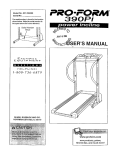
Model No. 831.299240
Serial No.
Find the serial number in the location
shown below. Write the serial number
in the space above for reference.
Serial
Number
Decal
HELPLINE!
/-800-735-5879
SEARS, ROEBUCK AND CO.
HOFFMAN ESTATES, IL 60179
USER'S MANUAL
PRO'FORA4 59oas
TABLE OF CONTENTS
IMPORTANT PRECAUTIONS .................................................................
BEFORE YOU BEGIN .......................................................................
ASSEMBLY ...............................................................................
OPERATION AND ADJUSTMENT
.............................................................
HOW TO FOLD AND MOVE THE TREADMILL" . _'._..'. i. i ........................................
MAINTENANCE AND TROUBLE-SHOOTING
...: .......
: .......................................
CONDITIONING GUIDELINES ........
_ • • _ _- .................................................
PART LIST ...............................................................................
ORDERING REPLACEMENT PARTS ......
• _ .:. ......
.'_ ...............................
FULL 90-DAY WARRANTY ............................................................
Note: An EXPLODED DRAWING is attached in the center of this manual.
3
5
6
8
15
16
18
19
Back Cover
Back Cover
IMPORTANT
1
PRECAUTIONS
t is the;res
3
21=When using i-Fit.com CD's and videos, an
24.1nspectandtigh
enal ipa i
t
,el
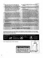
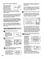
The decals shown below have been placed on your treadmill. If a decal is missing, or if it is not legible,
please call our toll-free HELPLINE to order a free replacement decal (see the back cover of this manual).
Apply the decal in the location shown.
Note: This decal is shown at 38% of actual size.
4
BEFORE YOU BEGIN
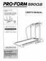
Thank you for selecting the revolutionary PROFORM ®
590QS treadmill. The 590QS treadmill combines advanced technology with innovative design to help you
get the most from your exercise program in the convenience and privacy of your home. And when you're not
exercising, the unique 590QS can be folded up, requiring less than half the floor space of other treadmills.
Monday through Saturday, 7 a.m. until 7 p.m. Central
Time (excluding holidays). To help us assist you,
please note the product model number and serial number before calling. The model number of the treadmill
is 831.299240. The serial number can be found on a
For your benefit, read this manual carefully before
using the treadmill, If you have additional questions,
please call our toll-free HELPLINE at 1-800-736-6879,
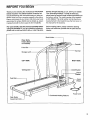
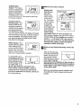
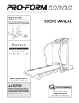
Before reading further, please review the drawing
below and familiarize yourself with the parts that are
labeled.
decal attached to the treadmill (see the front cover of
this manual for the location).
Book Holder
Water Bottle
Holder (Bottle
not included)
Pulse Bar
Handrail
Storage Latch
LEFT SIDE
RIGHT SIDE
Walking
Switch
Circuit
Breaker
Foot Rail
Front
Wheel
Powe Cord
Cushioned Walking Platform
r Roller
Adjustment Bolts
5
SSEMBLY
Assembly requires two people. Set the treadmill in a cleared area and remove all packing materials. Do not
dispose of the packing materials until assembly is completed. Assembly requires the included allen wrenc_
and your own phillips screwdriver (_3
=====_•
Note: The underside of the treadmill walking belt is coated with high-performance lubricant. During shipping, a
small amount of lubricant may be transferred to the top of the walking belt or the shipping carton. This is a normal
condition and does not affect treadmill performance. If there is lubricant on top of the walking belt, simply wipe off
the tubdcant with a soft cloth and a mild, non-abrasive c_eaner.
,
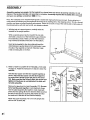
With the help of a second person, carefully raise the
treadmill to the upright position.
While a second person tips the treadmill to one side
and holds it, insert one of the Extension Legs (103) into
the treadmill as shown. Make sure that the Extension
Leg is turned so the Base Pad (97) is on the bottom.
Next, tip the treadmill to the other side and insert the
other Extension Leg (not shown) in the same way. Lower
the side of the treadmill so that both Extension Legs
(103) are resting flat on the floor.
\
97
.
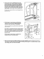
Refer to HOW TO LOWER THE TREADMILL FOR USE
on page 15. Follow the instructions in step 2 to lower the
treadmill.
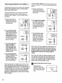
Hold the latch spacer and the latch support together as
shown. Attach the latch spacer and the latch support to
the center hole in the left Updght (82) with a 3/4" Screw
(89). Make sure that the Screw is tight, but do not overtighten it; if the Screw is overtightened, the latch will
not slide smoothly.
Remove the tape from the Latch Assembly (77), Be careful to hold the parts together. Inset drawing A shows
how the Latch Assembly fits together. Inset drawing B
shows how the springs fit into the bracket. Make sure that
the tabs on the latch are touching the bracket and that
the back end of the latch is flush with the bracket.
Attach the Latch Assembly (77) to the left Upright (82)
with two 3/4" Screws (89).
3. Slide the upper end of a Handrail (85) into the right
Upright (82) as shown. Note: It will be necessary to
pivot the Handrail to the side and back repeatedly
(see arrow A) while pushing on the Handrail (see
arrow B) to slide it fully into the Upright. Next, pivot
the lower end of the Handrail down, push it toward the
right Upright, and then align it with the indicated hole.
3
Slide the other Handrail (85) into the left Upright (82) as
described above.
Hole
4. With the help of a second person, carefully tip the
Uprights (82) down as shown. Make sure that the
Extension Legs (103) remain in the Uprights.
4
Attach each Extension Leg (103) with two Short Screws
(101) as shown.
Next, tighten a Handrail Bolt (78) with a Handrail Washer
(96) into each Extension Leg (103) and Handrail (85) as
shown. Note: It may be necessary to move the Handrails
up or down to align the Handrails with the holes in the
Extension Legs.
82
8201
°°
With the help of a second person, carefully tip the
Uprights (82) back to the upright position.
1 03 78
1o3 '"
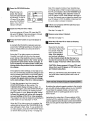
5. Make sure that all parts are tightened before you use the treadmill. Keep the included allen wrench in a
secure place. The allen wrench is used to adjust the walking belt (see page 17), To protect the floor or carpet
from damage, place a mat under the treadmill.
7
OPERATION-AND
THE PERFORMANT LUBE
TM
ADJUSTMENT
WALKING
BELT
Your treadmill features a walking belt coated with
PERFORMANT LUBE_, a high-performance lubricant.
IMPORTANT: Never apply silicone spray or other
substances to the walking belt or the walking platform. Such substances will deteriorate the walking
belt and cause excessive wear.
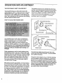
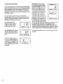
HOW TO PLUG IN THE POWER CORD
--
This product is for use on a nominal 120-volt circuit,
and has a grounding plug that looks like the plug illustrated in drawing 1 below. A temporary adapter that
looks like the adapter illustrated in drawing 2 may be
used to connect the surge suppressor to a 2-pole
receptacle as shown in drawing 2 if a properly
grounded outlet is not available.
1
]_\J
-Grounded
Outlet Box
,._
Surge Suppressor
joS-- _...
Grounding
Pin
Grounding Pin
Grounded Outlet
Grounding Plug
Grounded Outlet Box
Your treadmill, like any other type of sophisticated
electronic equipment, can be seriously damaged by
sudden voltage changes in your home's power.
Voltage surges, spikes, and noise interference can
result from weather conditions or from other appliances
being turned on or off. To decrease the possibility
of
your treadmill being damaged, always use a surge
suppressor with your treadmill (see drawing I at
the right).
Surge suppressors are sold at most hardware stores
and department stores. Use only a single-outlet surge
suppressor that is UL 1449 listed as a transient voltage
surge suppressor (TVSS). The surge suppressor must
have a UL suppressed voltage rating of 400 volts or
less and a minimum surge dissipation of 450 joules.
The surge suppressor must be electrically rated for
120 volts AC and 15 amps.
This product must be grounded. If it should malfunction or break down, grounding provides a path of least
resistance for electric current to reduce the risk of electric shock. This product is equipped with a cord having
an equipment-grounding conductor and a grounding
plug. Plug the power cord into a surge suppressor,
and plug the surge suppressor into an appropriate
outlet that is properly installed and grounded in
accordance with all local codes and ordinances.
8
Adapter
Surge Suppressor
Metal Screw
The temporary adapter should be used only until a
properly grounded outlet (drawing 1) can be installed
by a qualified electrician.
The green-colored rigid ear, lug, or the like extending
from the adapter must be connected to a permanent
ground such as a properly grounded outlet box cover.
Whenever the adapter is used it must be held in place
by a metal screw. Some 2-pole receptacle outlet box
covers are not grounded. Contact a qualified electrician to determine if the outlet box cover is
grounded before using an adapter.
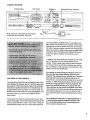
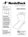
CONSOLE DIAGRAM
Incline _)isplay
LED Track
Displays
Manual/i-Fit.corn Indicators
...
.=.
-"-: --'-==)
Note: If there is a thin sheet of clear plastic
on the face of the console, remove it.
your home stereo, portable stereo, or computer, and
play special i-Fit.corn CD's (not included). These CD's
interactively control the speed and incline of the treadmill while a personal trainer coaches you through each
step of your workout. High-energy music provides added
motivation. Each CD features two different 30-minute
workout programs designed by certified personal
trainers.
In addition, you can connect the treadmill to your VCR
and TV and play i-Fit.com videocassettes (not included). These unique videos offer the same benefits
as i-Fit.corn CD's, but add the excitement and motivation of working out with a group and an instructor--the
hottest new trend at health clubs.
FEATURES OF THE CONSOLE
The treadmill console oliers an impressive array of features designed to help you get the most from your exercise program. When the manual mode of the console is
selected, the speed and incline of the treadmill can be
changed with a touch of a button. As you exercise, four
displays will provide continuous exercise :feedback. You
can even measure you heart rate using the built-in
pulse sensor.
The console also features revolutionary i-Fit.corn interactive technology. This breakthrough technology is like
having a personal trainer right in your home. Using the
included audio cable, you can connect the treadmill to
By plugging an optional upgrade module into the console, you can add virtually endless options to your
treadmill. The upgrade module enables you to connect
the treadmill to your home computer and log on to
www.i-fit.com, our powerful intemet site to be launched
October 1, 1999. By accessing www.i-fit.com, you can
download a large selection of workout programs that
match your specific exercise goals; access CD and
video workouts via the internet; participate in live webcast workouts; and watch exercise demonstrations via
web video conferences. You can even chat live with
your personal trainer and get individual fitness instruction.
To purchase i-Fit.corn CD's or videocassettes, or
to purchase the optional upgrade module, visit
your local department store or sporting goods
store or go to www.i-fit,com.
9
STt_P-BY-STEP
CONSOLE
OPERATION
Before operating the console, make sure that the
on/off switch near the
Position
power cord is in the on
position. Next, make sure
that the key is removed
from the console and the power cord is properly
plugged in (see HOW TO PLUG IN THE POWER
CORD on page 8).
begin walking. As you exercise, change .the speed
of the walking belt as desired by pressing the
SPEED buttons.
One{
To stop the walking belt, press the START/STOP
button. The TIME/MIN-MILE display will begin to
flash. To restart the walking belt, press the START/
STOP button or the SPEED _ button.
B
To change the incline of the treadmill, press the
incline buttons. Each time a button is pressed, the
incline will change by 0.5%. The buttons can be
held down to change the incline rapidly.
When you are ready to begin exercising, step onto the
foot rails of the treadmill. Find the clip attached to the
key (see the drawing on page 9), and slide the clip
onto the waistband of your clothing.
To use the manual mode, follow the steps below
and on page 11. To use i-Fit.com CD's or videocasaettes (not included), refer to pages 12 and 13. To
use other i-Flt.com technology, see page 13.
"r'_°
I1'
B
" "
Seleot the manual mode.
When the key is inserted, the manual
mode will automatically
be selected. If the iFit.com indicator is lit,
press the PROGRAM
button to select the
manual mode.
_1
Press the START/STOP button or the SPEED
button to start the walking belt.
A moment after the button is pressed, the walking belt will begin to
move at 1 mph. Hold the
handrails and carefully
'll
I|
o
'''
o
o
o
o
J
'/' '"
'='_"="
Note: In the incline display, the first indicator will
light when the incline is set at 1.5%. The second
indicator will light when the incline is set at 2% or
2.5%, the third indicator will light when the incline
is set at 3% or 3.5%, and so forth. After the incline
buttons are pressed, it will take a moment for the
treadmill to reach the selected incline setting.
Insert the key fully into the console.
When the key is
inserted, the four displays and various indicatom on the console
will light.
e
IF- ,nc,oeOisp,ay
'
Note: The console can display speed and distance in
either miles or kilometers (see SPEED DISPLAY on
page 1 I). For simplicity, all instructions in this manual
refer to miles.
D
Change the incline of the treadmill as desired.
g
Follow your progress with the LED track and
the four displays.
The LED Track-The LED track
oOO
O •
• •
represents a disOO
00
tance of 1/4 mile.
As you exemise,
the indicators
around the track
will light one at a
time until you have completed 1/4 mile. A new lap
will then begin.
play--This display shows
Ar w
the distance that you
LO "7
have walked or run and
""
the number of laps you
D=STANCELAPS
have completed (one lap
equals 1/4 mile). The display will alternate
between one number and the other every seven
seconds, as shown by the arrows in the display.
o,....c....o°,s
it
]
TIME/MIN-MILE
Measure your pulse, if desired.
display--This display
shows the elapsed time
and your current pace
(pace is measured in
minutes per mile). Your
pace will be shown for three seconds each time
the speed is adjusted.
Stand on the
foot rails and
place your
hands on the
metal contacts
on the pulse
bar. Your palms
must be resting
on the upper
contacts, and
your fingers must
be touching the
lower contacts--
CALS./FAT CALSJ
.GKG
;_
PULSE
PULSE display--This
display shows the approximate numbers of
calories and fat ca/ones
CALORIES FAT CALS.
you have burned (see
FAT BURNING on page
18). Every seven seconds, the display will change
from one number to the other, as shown by the arrows in the display. This display will also show
your heart rate when the pulse sensor is used
(see step 6 on this page).
_ t22]
SPEED display--This
display shows the speed
of the walking belt, in
miles per hour or kilometers per hour. The letters
"MPH" or =KPH" will show
which unit of measurement is selected.
measurement, hold down
the START/STOP button
To change
the the
unit key
of
while
inserting
7
SPEED _-]
into the console. An "E,"
for english miles, or an
=M," for metric kilometers, will appear in the
SPEED display. Press the SPEED zl button to
change the unit of measurement. When the desired unit of measurement is selected, remove and
then reinsert the key.
i[ E
Metal Contacts
eEKG2
PULSE
CALORIES
FAT CALS.
l" 12sl
avoid moving
your hands. When your pulse is detected, the
heart-shaped indicator in the CALS./FAT CALS./
PULSE display will flash steadily and a series Of
dashes (-- --) will appear. After a few seconds,
your heart rate will be shown. For the most accurate heart rate reading, continue to hold the
contacts for about 15 seconds.
B
I
When you are finished exercising, remove the
key.
Step onto the foot rails,
press the START/STOP
button, and remove the
key from the console.
Keep the key in a secure
place. Note: If the displays and various indicators on the console remain lit after the key is removed, the console is
in the "demo" mode. Refer to page 14 and turn
off the demo mode.
When you are finished using the treadmill, move
the on/off switch near the power cord to the off
position.
11
To use i-Fit.com videos, you must connectjhe treadmill to your VCR or TV. To do this, follow steps A to C
below.
Topurchasei-Fit.comCD'sandvideos(notincluded),
visityourlocaldepartment
storeor sportinggoods
storeorgotowww.i-fit.com+
To use i-Fit.corn CD's, you must first connect the
treadmill to your home stereo, portable stereo, or
computer with CD player. To do this, follow steps A
to D below.
A. Plug one end of the included audio cable into
the jack near the treadmill power cord.
A. Plug one end of the included audio cable into
the jack near the treadmill
power cord.
AUDIO OUT jack on the
portable stereo.
Cable
-_
o, ,j
i
into the included adapter
and plug the adapter into
an AUDIO OUT jack on
the VCR.
Cable V
C. To connect the treadmill to a TV, plug the
other end of the audio
cable into the included
adapter and plug the
adapter into an AUDIO
OUT jack on the TV.
o+, j
Adapter-_
Audio._l
Cable V
C. To connect the treadmill to a portable
stereo, plug the other
end of the audio cable
into e LINE OUT or an
J_
B. To connect the treadmill
to a VCR, plug the other
end of the audio cable
Cable'--_'-Audio
_
B. To connect the treadmill to a home stereo,
plug the other end of the
audio cable into the included adapter and plug
the adapter into a LINE
OUT or an AUDIO OUT
jack on the stereo.
Audio
Cable V
I.==o
I
+
Audio
Note: If your VCR is connected to a home stereo, you
may connect the audio cable to the home stereo as
descdbed in step B at the left. Remember, you must
be able to listen to the audio through speakers or
headphones in order to use i-Fit.com CD's or
videos.
I_
Cable _7
D. To connect the treadmill to e computer, plug
the other end of the
audio cable into a LINE
OUT or an AUDIO OUT
jack on the computer.
Audio
[
_
I
Cable V
Note: Depending on the model of your stereo or computer, the jacks may be labeled differently. You may
need to connect the audio cable to a SPEAKER jack or
a HEADPHONE jack. To do this, you must purchase a
Y-adapter at your local electronics store. CAUTION:
You must be able to listen to the audio through
speakers or headphones in order to use i-Fit.com
CD's or videos.
/2.
When the audio cable is properly connected, make
sure that the on/off switch near the treadmill power
cord is in the on position. Next, make sure that the
power cord is properly plugged in. Follow the steps
below to use an i-Fit.corn CD or video.
D
Insert the key fully into the console,
When the key is
inserted, the four displays and various indicators on the console will
I_ght.
la
Press the PROGRAM button.
Note: If the speed or incline of your treadmill does
not change when a "chirp" is heard, make sure that
the i-Fit.corn indicator is lit and the TIME/MIN-MiLE
display is not flashing. Next, adjust the volume of
your CD player or VCR. if the volume is too high or
too low, the console may not detect the signals from
your CD player or VCR. in addition, make sure that
the audio cable is propedy connected.
When the key is inserted, the manual
mode will automatically
be selected. To use an
i-Fit.corn CD or video,
press the PROGRAM
button. The i-Fit.com
indicator will light.
[]Follow
your progress with the LED track and
the four displays.
1_1 Insert the i-Fit.com CD or video.
If you are using an i-Fit.corn CD, insert the CD
into your CD player. If you are using an i-Fit.corn
video, insert the video into your VCR.
See step 5 on page 10.
r_
Measure your pulse, if desired.
See step 6 on page 11.
B
Press
VCR. the PLAY button on your CD player or
A moment after the button is pressed, your personal trainer will begin guiding you through your
workout. Simply follow your personar trainer's
instructions.
During the CD or video program, an electronic
"chirping"sound will alert you when the speed
and/or incline of the treadmill is about to change.
CAUTION: Always listen for the "chirp" and be
prepared for speed and/or incline changes. In
some instances, the speed and/or incline may
change before the personal trainer describes
the change.
If the speed or incline settings are too high or too
low, you can manually override the settings at any
time by pressing the SPEED or INCLINE buttons
on the console. However, when the next "chirp"
is heard, the speed and/or incline will change
to the next settings of the CD or video program.
To stop the program at any time, press the
START/STOP button on the console. The
TIME/MIN-MILE display will begin to flash. To
restart the program, press the START/STOP button again. After a moment, the walking belt will
begin to move at 1 mph. When the next "chirp"
is heard, the speed and incline will change to
the next settings of the CD or video program.
The program can also be stopped by pressing the
STOP button on your CD player or VCR.
When the CD or video program is completed, the
walking belt will stop and the TIME/MIN-MILE display will begin to flash. Note: To use another CD
or video program, press the START/STOP button
or remove the key and go to step 1 on page 12.
B
When the i-Fit.com CD or video is finished,
remove the key.
Step onto the foot rails
and remove the key from
the console. Keep the
key in a secure place.
Note: If the displays
and various indicators
on the console remain lit after the key is removed, the console is in the "demo" mode.
Refer to page 14 and turn off the demo mode.
CAUTION: Always remove i-Fit.com CD's and
videos from your CD player or VCR when you
are finished using them.
When you are finished using the treadmill, move
the on/off switch near the power cord to the off
position.
By adding the optional upgrade module to the console,
you can add virtually endless options to your treadmill
To purchase the upgrade module, visit your local
department store or sporting goods store or go to
www.i-fit.com.
Instructions for using other i-Fit.corn options will be
included with the upgrade module. In addition, make
sure to explore www.i-fit.com to learn more about
how you can get the most from i-Fit.corn technology!
13
THEINFORMATIONMODE
The console features an information mode that keeps
track of the total number of hours that the treadmill has
been operated and the total number of miles that the
walking belt has moved. The information mode also
allows you to switch the console from miles per hour to
kilometers per hour.
To select the information mode, hold down the
START/STOP button while inserting the key into the
console. When the information mode is selected, the
following information will be shown:
•
display will show the total
number of miles that the
walking belt has moved.
IMPORTANT: The CALSJ
FAT CALSJPULSE display
should be blank. If a "d" appears in the display, the conV EKG_-PULSE
1
sole is in the "demo" mode.
CALORIES
FAT CALS.
This mode is intended to be
used only when a treadmill is
displayed in a store. When
uEKG2 PULSE
the console is in the demo
mode, the power cord can be
plugged in, the key can be reCALORIES
FAT CALS.
moved from the console, and
the displays and indicators on
the console will automatically
light in a preset sequence, although the buttons on the
console will not operate. If a "d" appears in the
CALSJFAT OALSJ PULSE display when the information mode is selected, press the SPEED _7 button
l
Ii 121
|
|
OtSTANCE
LAPS
so the CALSJ FAT CALSJPULSE
The TIME/MIN-MILE display
will show the total number of
hours the treadmill has been
used.
An "E," for english miles, or
an =M," for metric kilometers,
will appear in the SPEED display. Press the SPEED A button to change the unit of measurement.
.)
II 311
TIME
MIN/MILE
(kin)
display is blank.
To exit the information mode, remove the key from the
console.
HOW TO FOLD AND MOVE THE TREADMILL
HOW TO FOLD THE TREADMILL
FOR STORAGE
Before folding the treadmill, adjust the incline to the
lowest position. If this is not done, the treadmill may be
permanently damaged. Next, unplug the power cord.
CAUTION: You must be able to safely lift 45 pounds (20
kg) in order to raise, lower, or move the treadmill.
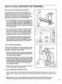
1. Hold the treadmill with your hands in the locations shown
at the right. CAUTION: To decrease the possibility of injury, bend your legs and keep your back straight. As
you raise the treadmill, make sure to lift with your legs
rather than your back. Raise the treadmill about halfway
to the vertical position.
2. Move your right hand to the position shown and hold the
treadmill firmly. Using your left thumb, slide the storage
latch to the left and hold it. Raise the treadmill until the
Open
storage latch closes over the catch. Make sure that the
storage latch is fully closed over the latch catch.
To protect the floor or carpet from damage, place a
mat under the treadmill. Keep the treadmill out of
direct sunlight. Do not leave the treadmill in the storage position in temperatures above 85 ° Fahrenheit.
Closed
HOW TO MOVE THE TREADMILL
Before moving the treadmill, convert the treadmill to the storage position as described above. Make sure that the storage latch is closed fully over the catch,
Book Holder
1. Hold the handrails as shown and place one foot against a
wheel. Do not hold or push on the book holder or the
book holder may be damaged.
2. Tilt the treadmill back until it rolls freely on the front wheels.
Carefully move the treadmill to the desired location. Never
move the treadmill without tipping it back. To reduce
the risk of injury, use extreme caution while moving
the treadmill. Do not attempt to move the treadmill
over an uneven surface.
3. Place one foot on the base, and carefully lower the treadmill until it is resting in the storage position.
HOW TO LOWER THE TREADMILL
FOR USE
1. Refer to drawing 2 above. Hold the upper end of the treadmill with your right hand as shown. Using your left
thumb, slide the storage latch to the left and hold it. Pivot the treadmill down until the frame is past the storage
latch.
2. Refer to drawing 1 above. Hold the treadmill firmly with both hands, and lower the treadmill to the floor.
CAUTION: To decrease the possibility of injury, bend your legs and keep your back straight.
15
-
_.
.
TROUBLE-SHOOTING
Most treadmill problems can be solved by following the simple steps below. Find the symptom that
applies, and follow the steps listed. If further assistance is needed, call our toll-free HELPLINE at
1-800-736-6879, Monday through Saturday, 7 a.m. until 7 p.m. Central Time (excluding holidays).
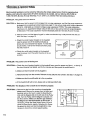
PROBLEM:
The power does not turn on
SOLUTION:
a. Make sure that the power cord is plugged into a surge suppressor, and that the surge suppressor
is plugged into a properly grounded outlet (see page 7). Use only a single-outlet surge suppressor
that is UL 1449 listed as a transient voltage surge suppressor (TVSS). The surge suppressor
must have a UL suppressed voltage rating of 400 volts or less and a minimum surge dissipation
of 450 joules. The surge suppressor must be electrically rated for 120 volts AC and 15 amps.
b. After the power cord has been plugged in, make sure that the key is fully inserted into the console. See step 1 on page 10.
C°
check the circuit breaker located on the treadmill
near the power cord. If the switch protrudes as
shown, the circuit breaker has tripped. To reset the
circuit breaker, wait for five minutes and then press
the switch back in.
d. Check the on/off switch located on the treadmill
near the power cord. The switch must be in the on
position.
c
Tripped
_
Reset
S
d
Position
PROBLEM:
The power turns off during use
SOLUTION:
a. Check the circuit breaker located on the treadmill frame near the power cord (see 1. c. above). If
the circuit breaker has tripped, wait for five minutes and then press the switch back in.
b. Make sure that the power cord is plugged in.
c. Remove the key from the console. Reinsert the key fully into the Console. See step I on page 10.
d. Make sure that the on/off switch is in the on position.
e. If the treadmill still will not run, please call our toll-free HELPLINE.
PROBLEM:
The displays of the console do not function properly
SOLUTION:
a. Remove the key from the console and unplug the
power cord. Remove the screws from the hood and
carefully remove the hood. Locate the Reed Switch
(21) and the Magnet (43) on the left side of the Pulley
(42). Turn the Pulley until the Magnet is aligned with
the Reed Switch, Make sure that the gap between
the Magnet and the Reed Switch is about 1/8". If
necessary, loosen the Reed Switch Screw (76) and
move the Reed Switch slightly. Retighten the Screw.
Re-attach the hood, and run the treadmill for a few
minutes to check for a correct speed reading.
I
I
1/8"--_
76_.
2tl
Top
View
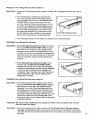
PROBLEM:The walkingbelt slowswhenwalkedon
SOLUTION:
a. Use only a UL-listed surge protector, rated at 15 amps, with a 14-gauge cord of five feet or less in
length.
b,
If the walking belt is overtightened, treadmill performance may decrease and the walking belt may become damaged. Remove the key and UNPLUG THE
POWER CORD. Using the allen wrench, turn both
rear roller adjustment bolts counterclockwise, 1/4 of a
turn. When the walking belt is properly tightened, you
should be able to lift each side of the walking belt 3 to
4 inches oft the walking platform. Be careful to keep
the walking belt centered. Plug in the power cord, insert the key and run the treadmill for a few minutes.
Repeat until the walking belt is properly tightened.
b
3"--4"
Rear Roller Adjustment Bolts
c. If the walking belt still slows when walked on, please call our toll-free HELPLINE.
PROBLEM: The walking belt is off-center
SOLUTION:
a. If the walking belt has shifted to the left, first remove
the key and UNPLUG THE POWER CORD. Using the
allen wrench, turn the left rear roller adjustment bolt
clockwise, and the right bolt counterclockwise, 1/4 of a
turn each. Be careful not to overtighten the walking belt.
Plug in the power cord, insert the key and run the treadmill for a few minutes. Repeat until the walking belt is
centered.
b. If the walking belt has shifted to the right, first remove the key and UNPLUG THE POWER CORD.
Using the allen wrench, turn the left rear roller adjustment bolt counterclockwise, and the right bolt clockwise,
1/4 of a turn each. Be careful not to overtighten the
walking belt. Plug in the power cord, insert the key and
run the treadmill for a few minutes. Repeat until the
walking belt is centered.
PROBLEM:
The walking belt slips when walked on
SOLUTION:
a. If the walking belt slips when walked on, first remove
the key and UNPLUG THE POWER CORD. Using the
allen wrench, turn both rear roller adjustment bolts
clockwise, 1/4 of a turn. When the walking belt is correctly tightened, you should be able to lift each side of
the walking belt 3 to 4 inches off the walking platform.
Be careful to keep the walking belt centered. Plug in the
power cord, insert the key and carefully walk on the
treadmill for a few minutes. Repeat until the walking belt
is properly tightened.
PROBLEM:
The incline of the treadmill does not change correctly or does not change when i-Fit.corn
CD's and videos are played
SOLUTION:
a. With the key inserted in the console, press one of the INCLINE buttons. While the incline is
changing, remove the key. After a few seconds, re-insert the key, The treadmill will automatically rise to the maximum incline level and then return to the minimum level. This will recalibrate
the incline.
17
( ONDITIONING
GUIDELINES
uses easily accessible carbohydrate calories for energy. Only after the first few minutes does your body
begin to use stored fat calories for energy. If your goal
is to burn fat, adjust the speed and incline of the treadmill until your heart rate is near the lowest number in
your training zone.
For maximum fat burning, adjust the speed and incline
of the treadm!ll until your heart rate is near the middle
number in your training zone.
Aerobic Exercise
The following guidelines will help you to plan your exercise program. Remember--these
are general guidelines only. For more detailed exercise information, obtain a reputable book or consult your physician.
EXERCISEINTENSITY
Whether your goal is to burn fat or to strengthen your
cardiovascular system, the key to achieving the
desired results is to exercise with the proper intensity.
The proper intensity level can be found by using your
heart rate as a guide. The chart below shows recommended heart rates for fat burning and aerobic exercise.
To find the proper heart rate for you, first find your age
near the bottom of the chart (ages are rounded off to
the nearest ten years). Next, find the three numbers
above your age. The three numbers define your "training zone." The lower two numbers are recommended
heart rates for fat burning; the higher number is the
recommended heart rate for aerobic exercise.
To measure your heart rate during exercise, use the
pulse sensor on the console, if your heart rate is too
high or too low, adjust the speed and incline of the
treadmill.
Fat Burning
To burn fat effectively, you must exercise at a relatively
low intensity level for a sustained period of time.
During the first few minutes of exercise, your body
18
If your goal is to strengthen your cardiovascular system, your exercise must be "aerobic." Aerobic exercise
is activity that requires large amounts of oxygen for
prolonged periods of time. This increases the demand
on the heart to pump blood to the muscles, and on the
lungs to oxygenate the blood. For aerobic exercise,
adjust the speed and incline of the treadmill until your
heart rate is near the highest number in your training
zone.
WORKOUT
GUIDELINES
Each workout should include the following three parts:
A Warm-up---Start each workout with 5 to 10 minutes
of stretching and light exercise. A proper warm-up increases your body temperature, heart rate and circulation in preparation for exercise.
Training Zone Exerclse--After warming up, increase
the intensity of your exercise until your pulse is in your
training zone for 20 to 60 minutes. (During the first few
weeks of your exercise program, do not keep your
pulse in your training zone for longer than 20 minutes.)
Breathe regularly and deeply as you exercise--never
hold your breath.
A Cool-down--Finish
each workout with 5 to 10 min-
utes of stretching to cool down. This will increase the
flexibility of your muscles and will help prevent post-exercise problems.
Exercise Frequency
To maintain or improve your condition, complete three
workouts each week, with at least one day of rest between workouts. After a few months, you may complete up to five workouts each week if desired.
The key to success is to make exercise a regular and
enjoyable part of your everyday life.
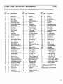
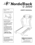
PART LIST--Model
No. 831.299240
RoaggA
To locate the parts listed below, refer to the EXPLODED DRAWING attached in the center of this manual.
Key
No.
Qty.
1
2
3
1
1
4
Motor Belt
Pulley/Flywheel/Fan
Motor Nut
4*
1
5
2
Motor/Pulley/
Flywheel/Fan
Incline Motor Bolt
6
7
8
9
10
11
12
13
14
15
16
17
18
19
20
21
22
23
24
25
26
27
28
29
30
31
32
33
34
35
36
37
1
1
1
1
2
1
1
1
1
8
14
4
2
2
2
1
1
1
1
1
1
1
1
1
1
1
2
2
1
1
5
2
38
39
40
41
42
4
4
1
2
1
Description
Incline Motor Spacer
Incline Motor
Stop Bracket
Small Nut
Star Washer
Optic Switch
Frame
Small Bolt
Incline Optic Disk
Incline Motor Nut
Screw
Plastic Stand-Off
Hood Bracket (short)
Hood Bracket (long)
Warning Decal
Reed Switch
Reed Switch Clip
Motor/Controller Wire
Controller
Electronics Bracket
Circuit Breaker
Power Cord
Power Cord Gromme!
On/Off Switch
Inlet Bracket
Inciine Leg
Frame Pivot Bolt
Frame Pivot Spacer
Upright Wire Harness
Front Roller Adj. Bolt
Roller Adj. Washer
Motor Tension Nut/
Front Roller Nut
Motor Bolt
Cap Screw
Left Foot Rail Cap
Foot Rail
Front Roller/Pulley
Key
No.
Qty.
Key
No.
Qty.
43
44
45
46
47
48
49
1
6
4
4
15
1
2
Magnet
Platform Screw
Isolator
Isolator Screw
Belly Pan Fastener
Shield
Belt Guide
85
86
87
88
89
90
91
2
2
1
1
11
1
1
50
51
52
53
54
55
56
1
1
1
4
4
1
1
Console Cover
Front Belly Pan
Power Supply
Cable Tie Clamp
Cable Tie
Walking Belt
20" Wire Harness
92
93
94
95
96
97
98
1
1
1
2
1
4
1
Right Foot Rail Cap
Book Holder
Motor Hood
Front Wheel
Incline Motor Shield
Base Pad
12" Audio Wire
57
58
59
60
61
62
63
64
65
66
67
68
69
70
71
72
73
74
75
76
1
2
2
2
1
7
1
1
2
1
1
2
2
1
1
5
1
1
1
12
77
78
79
80
81
82
83
84
1
2
4
1
4
1
2
2
Rear Roller
Rear Isolator
Rear Foot
Rear Foot Screw
Ground Wire
Ground Wire Screw
Belly Pan
Rear Endcap
Rear Roller Adj, Bolt
Motor
Latch Decal
Rear Platform Screw
Catch Screw
Latch Catch
Walking Platform
8" cable Tie
Jack
Motor Tension Bolt
Left Foot Rail Insert
Reed Switch Screw/
Belly Pan Screw
Storage Latch
Handrail Bolt
Long Screw
10' I-Fit Wire
Motor Star Washer
Upright
Incline Leg Pivot Bolt
Incline Leg Pivot
Washer
99
100
101
102
103
104
105
106
107
108
109
110
#
#
#
#
#
#
#
#
#
#
#
1
1
17
1
2
2
1
1
2
2
1
2
1
1
1
1
1
1
1
1
1
1
1
Upright Grommet
Allen Wrench
Short Screw
Upright Hole Plug
Extension Leg
Extension Leg Gap
Shock
Choke
Pulse Bar Bolt
Pulse Bar Washer
Pulse Bar
Handrail Insert
10" White Wire, 2F
8" White Wire, 2F
4" White Wire, M/F
9" Wire Harness
8" Blue Wire, 2F
4" Blue Wire, 2F
4" Black Wire, 2F
4" Green Wire, FIRing
8" Green Wire, F/Ring
8" Green Wire, 2 Ring
User's Manual
Description
Description
Handrail
Wheel Bolt
Console Base
Console
3/4" Screw
Key/Clip
Incline Motor Plate
* Includes all parts shown in the
box
# These parts are not illustrated
19
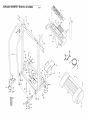
EXPLODED DRAWING--Model
107
No. 831.299240
-R0899A
108
9O
34
87
93
,89
109
77
89
84
83
i
86
i
73
84
20
11
16
I
15
i
_101
103
34
16
99
86
-_
105
..'"
"'" 20
•
101
100
1_
°"
101
94
"
-
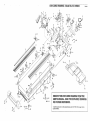
EXPLODED
4_
DRAWINGmModel
No. 831.299240
R0899A
37
25
15
41
32
75
45
4.
71
45
55
I
76
47
57
67
REMOVE THIS EXPLODED DRAWING FROM THE
USER'S MANUAL. SAVE THE EXPLODED DRAWING
FOR FUTURE REFERENCE.
63I
65
i
61
=
0
To identify the parts shown on this exploded drawing, refer to the PART LIST on page 19 of the
USER'S MANUAL.
The model number and serial number of your PROFORM ®590QS
treadmill are listed on a decal attached to the frame, See the front
cover of this manual to find the location of the decal,
Model No. 831.299240
All replacement parts are available for immediate purchase or
special order when you visit your nearest SEARS Service Center.
To request service or to order parts by telephone, call the toil-free
numbers listed at the left.
QUESTIONS?
if you find that:
• you need help assembling
operating the PROFORM
590QS treadmill
or
When requesting help or service, or ordering parts, please be
prepared to provide the following information:
• a part is missing
• The NAME OF THE PRODUCT (PROFORM '_590QS treadmill)
• or you need to schedule repair
service
• The MODEL NUMBER OF THE PRODUCT (831.299240)
call our toll-free HELPLINE
• The KEY NUMBER AND DESCRIPTION OF THE PART (see the
EXPLODED DRAWING and PART LIST included in this manual
1-800-736-6879
Monday-Saturday,
7 am-7 pm
Central Time (excluding holidays)
REPLACEMENT
PARTS
If parts become worn and need
to be replaced, call the following
toll-free number
1-800-FON-PART
(1-800-366-7278)
FULL 90 DAY WARRANTY
For 90 days from the date of pumhase, if failure occurs due to defect in materiai or workmanship in this
SEARS TREADMILL EXERCISER, contact the nearest SEARS Service Center throughout the United
States and SEARS will repair or replace the TREADMILL EXERCISER, free of charge.
This warranty does not apply when the TREADMILL
poses.
EXERCISER
is used commercially or for rental pur-
This warranty gives you specific legal rights, and you may also have other rights which vary from state
to state.
SEARS, ROEBUCK
Part No. 157778 RO899A
AND CO., DEPT. 817WA, HOFFMAN
ESTATES, IL 60179
Printed in USA © 1999 Sears, Roebuck and Co.