1
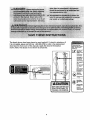
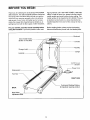
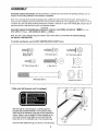
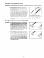
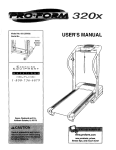
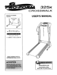
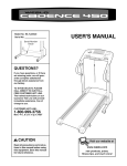
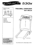
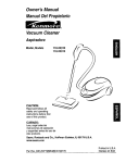
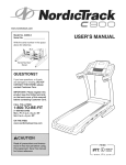
330x
TREADMILL
Model No. 831.293330
Serial No,
EXERCISER
User's Manual
Serial
Number
Decal
!
/
• Assembly
• Operation
• Maintenance
\
\
• P_rt List and Drawing
Sears, Roebuck
and Co., Hoffman
\
Estates, IL 60179
330x
TABLE OF CONTENTS
IMPORTANT PRECAUTIONS
................................................................
BEFORE YOU BEGIN ......................................................................
ASSEMBLY ...............................................................................
OPERATION AND ADJUSTMENT ............................................................
HOW TO FOLD AND MOVE THE TREADMILL ..................................................
TROUBLESHOOTING
.....................................................................
CONDITIONING GUIDELINES ...............................................................
ORDERING REPLACEMENT PARTS ..................................................
FULL 90 DAY WARRANTY ..........................................................
Note: An EXPLODED DRAWING and a PART LIST are attached in the center of this manual.
2
3
5
6
10
13
15
17
Back Cover
Back Cover
IMPORTANT PRECAUTIONS
The decals shown have been placed on your treadmill• If a decal is missing, or if
it is not legible, please call toll-free 1-800-999-3756 to order a free replacement
decal (see the front cover of this manual). Apply the decal in the location
shown. Note: The decals are not shown at actual size.
protect yourself and
o_*_ _om risk of serious
injury. Read the user's
manual and :
sm,l]l _r_n_
-HokJhandrailsto
a_ays
wear the
safelydip _ile
opera_g treadm_l.
!
• st_
_ you te_ taint
brea_
• Fully enga_
storage
_tch
_f_e
b'l_ad.
mill is r_vc_ _r
slomd,
lolding
•
_ea_i_i_
_to
ch[idt_ on c_
around
r,_ in use.
•Keepdothlng,
_y
_
KEEPHANDSANDFEETAWAY
FROMTHISAREAWHfLETHE
TREADMILL
ISIN OPERATION.
_'_,
I_m m_ng
_
t_r
-Nway_wear
BEFORE YOU BEGIN
Thank you for selecting the revolutionary PROFORM ®
330x treadmill. The 330x treadmill combines advanced
technology with innovative design to help you get the
most from your exercise program in the convenience
and privacy of your home. And when you're not exercising, the unique 330x treadmill can be folded up, requiring less than half the floor space of other treadmills.
ing this manual, call 1-800-4-MY-HOME ®(1-800-4694663).To help us assist you, please note the product
model number and serial number before calling. The
model number of the treadmill is 831.293330. The serial number can be found on a decal attached to the
treadmill (see the front cover of this manual for the location).
For your benefit, read this manual carefully before
using the treadmill. If you have questions after read-
Before reading further, please review the drawing
below and familiarize yourself with the labeled parts.
Bookrack
Water Bottle Holder
(Bottle not included)
Console
Key/Clip
Storage Latch
Upright
Handrail
OniOii Circuit
Breaker
Cord
Walking Belt
\
RIGHT SIDE
Cushioned Walking Platform
for maximum exercise comfort
BACK
Rear Roller
Adjustment Bolts
5
ASSEMBLY
Assembly requires two persons. Set the treadmill in a cleared area and remove all packing materials. Do not
dispose of the packing materials until assembly is completed.
Note: The underside of the treadmill walking belt is coated with high-performance lubricant. During shipping, a
small amount of lubricant may be transferred to the top of the walking belt or the shipping carton. This is a normal
condition and does not affect treadmill performance. If there is lubricant on top of the walking belt, simply wipe off
the lubricant with a soft cloth and a mild, non-abrasive cleaner.
Assembly requires the included allen wr_
wire cutters _
and your own phillips screwdriver
, and needlenose pliers _
.
Note: If a part is not in the parts bag, first check to see if it has been pre-assembled.
call toll-free 1-800-999-3756.
To identify small parts, use the PART IDENTIFICATION
Silver Ground
Screw (75)-1
(__,
If a part is missing,
CHART below.
3/4" Screw (2)-8
3/4" Tek Screw (58)-8
1©
1/2" Silver Screw (48)-1
1" Bolt (37)-6
Wheel Bolt (64)-2
Wheel Nut (104)-2
1. Make sure that the power cord is unplugged.
With the help of a second person, carefully raise the
Uprights (69) until the treadmill is in the position shown.
Insert one of the Extension Legs (63) into the treadmill as
shown. (Note: It may be helpful to tip the Uprights as you
insert the Extension Leg.) Make sure that the Warning
Decal (62) is on the indicated side of the Extension Leg.
Insert the other Extension Leg (not shown) in the same way.
6
63
2. With the help of a second person, carefully lower the
treadmill frame and then tip the Uprights (69) down as
shown. (Note: It may be helpful to place your foot on one
of the Extension Legs [63] as you tip the Uprights.) Make
sure that the Extension Legs remain in the Uprights.
2
/
58
Attach each Extension Leg (63) with two 3/4" Tek
Screws (58).
Attach four Base Pads (57) with 3/4" Tek Screws (58) as
shown.
Note: One replacement Base Pad (57) may be included•
If a Base Pad becomes worn and needs to be replaced,
use the replacement Base Pad.
3. With the help of a second person, raise the Uprights (69)
to the vertical Position• Attach the Storage Latch (36) to
the left Upright with two 3/4" Screws (2). Remove the
Latch Knob (30) from the Latch Pin (35). Make sure that
the Latch Pin Collar (33) and the Spring (32) are on the
Latch Pin as shown. Insert the Latch Pin into the Storage
Latch, and tighten the Latch Knob back onto the Latch
Pin.
I
57_-_
/
58
30
32
.33
35
4. Identify the Right Handrail (72), which has a large hole in
the left side. Feed the Wire Harness (42) up into the
bracket on the Right Handrail and out of the large hole in
the left side• (Note: It may be helpful to use needlenose
pliers to pull the Wire Harness out of the large hole.)
Press a Handrail Cap (76) onto the lower end of the
Right Handrail as shown.
• Insert the bracket on the Right Handrail (72) into the top
of the right Upright (69) so the Handrail Cap (76) is resting against the Upright. Attach the Right Handrail and the
Handrail Cap with three 1" Bolts (37) and two Washers
(38) as shown. Firmly tighten the indicated Bolt, but
do not tighten the other Bolts yet.
Attach the Left Handrail (not shown) as described above.
Note: There is not a wire harness on the left side.
7
Large
Hole
38
69
38
5. Attach the end of the ground wire to the small hole in the
side of the Hight Handrail (72) with a Silver Ground
Screw (75).
5
Ground
Wire
75
\
6. Place the Console Base (47) on the Right Handrail (72)
and the Left Handrail (not shown). Attach the Console
Base with four 3/4" Screws (2) (only two Screws are
shown). Do not overtighten the Screws.
Insert the Wire Hamess (42) through the two indicated
plastic ties on the Console Base (47). Next, touch the
Right Handrail (72) to discharge any static. Refer to the
inset drawing. Find the 3-wire connector on the end of the
Wire Harness (42). Insert the connector into the red
socket beneath the console. The connector should
slide easily into the socket and snap into place. If the
connector does not slide easily and snap into place, turn
the connector and then insert it.
6
47
72
2
43
Insert the 5-wire connector into the black socket beneath
the console in the same way.
Make sure that the connectors and wires appear as
shown at the right. IF THE CONNECTORS ARE NOT
INSERTED PROPERLY, THE CONSOLE MAY BE
DAMAGED WHEN THE POWER iS TURNED ON.
7. Insert the excess Wire Harness (42) into the large hole in
the side of the Right Handrail (72). Securely tighten the
plastic ties on the bottom of the Console Base (47) to
prevent the Wire Harness from slipping. Then, cut off
the ends of the plastic ties.
7
47
Ties
Route the Wire Harness (42) through the indicated opening in the Console Base (47). Attach the Wire Cover (44)
to the Console Base (47) with a 1/2" Silver Screw (48).
Tighten two 3/4" Screws (2) into the Console Base (47).
8
I
72
42
8. Attach a Wheel (66) to the inner side of each Extension
Leg (63) with a Wheel Bolt (64) and a Wheel Nut (104)
as shown. Do not overtighten the Bolts. The Wheels
should be able to turn freely.
Lift the treadmill frame (see HOW TO FOLD THE
TREADMILL FOR STORAGE on page 13), but do not
latch it. Make sure that the frame is centered between
the Handrails (not shown). Firmly tighten the bolts
used in assembly step 4. Then, lower the frame to the
floor.
66
9. Make sure that all parts are properly tightened before you use the treadmill. Note: Extra hardware may
be included, Keep the included allen wrenches in a secure place. The large allen wrench is used to adjust the
walking belt (see page 16). To protect the floor or carpet, place a mat under the treadmill.
9
OPERATION AND ADJUSTMENT
THE PERFORMANT
LUBE TM WALKING BELT
an equipment-grounding conductor and a grounding
plug. Plug the power cord into a surge suppressor,
and plug the surge suppressor into an appropriate
outlet that is properly installed and grounded in
accordance with all local codes and ordinances.
Your treadmill features a walking belt coated with
PERFORMANT LUBE TM, a high-performance lubricant.
IMPORTANT: Never apply silicone spray or other
substances to the walking belt or the walking platform. Such substances will deteriorate the walking
belt and cause excessive wear.
Important: The treadmill
GFCl-equipped outlets.
is not compatible with
This product is for use on a nominal 120-volt circuit,
and has a grounding plug that looks like the plug illustrated in drawing 1 below. A temporary adapter that
looks like the adapter illustrated in drawing 2 may be
used to connect the surge suppressor to a 2-pole
receptacle as shown in drawing 2 if a properly
grounded outlet is not available.
HOW TO PLUG IN THE POWER CORD
t/S_-Grounded
Outlet Box
_n"
Grounding Pin
SorooSuooro
Your treadmill, like any other type of sophisticated
electronic equipment, can be seriously damaged by
sudden voltage changes in your home's power.
Voltage surges, spikes, and noise interference can
result from weather conditions or from other appliances
being turned on or off. To decrease the possibility of
your treadmill being damaged, always use a surge
suppressor with your treadmill (see drawing 1 at
the right). To purchase a surge suppressor, see
your local Sears or call 1-800-366-7278 and order
part number 146148.
_
_F'_IIi _.J
Grou ded Outlet
,-,"...........
u_ourl,3tP_g
_._
hug
2
_Grounded
_J
Use only a single-ouUet surge suppressor that is
UL 1449 listed as a transient voltage surge suppressor (TVSS). The surge suppressor must have a
UL suppressed voltage rating of 400 volts or less
and a minimum surge dissipation of 450 joules.
The surge suppressor must be electrically rated
for 120 volts AC and 15 amps. There must be a
monitoring light on the surge suppressor to indicate whether it is functioning properly. Failure to
use a properly functioning surge suppressor could
result in damage to the control system of the
treadmill. If the control system is damaged, the
walking belt may change speed or stop unexpectedly, which may result in a fall and serious injury.
___.
Outlet Box
Adapter
^
.<
Surge buppressor
Metal Screw
The temporary adapter should be used only until a
propedy grounded outlet (drawing 1) can be installed
by a qualified electrician.
The green-colored rigid ear, tug, or the like extending
from the adapter must be connected to a permanent
ground such as a properly grounded outlet box cover.
Whenever the adapter is used it must be held in place
by a metal screw. Some 2-pole receptacle outlet box
covers are not grounded. Contact a qualified electrician to determine if the outlet box cover is
This product must be grounded, if it should malfunction or break down, grounding provides a path of least
resistance for electric current to reduce the risk of electric shock. This product is equipped with a cord having
grounded before using an adapter.
10
CONSOLE DIAGRAM
Displays
TIME
DISTANCE
FAT
CALS.
PULSE
SPEED
(
]
&.WARNING:
_1_
.
STOP
,o..,o ,o
Note: If there is a thin sheet of
plastic on the console, remove it.
Insert the key fully into the console. After a moment,
the displays will light. Test the clip by carefully taking a few steps backward until the key is pulled
from the console. If the key is not pulled from the
console, adjust the position of the clip.
Follow the steps below to operate the console.
B
Insert the key fully into the console.
A few seconds after the key is inserted, the displays will light.
B
STEP-BY-STEP
Press the Start button or the Speed G button to
start the walking belt.
A moment after the button is pressed, the walking
belt will begin to move. Hold the handrails and
begin walking.
CONSOLE OPERATION
As you exercise, change the speed of the walking
belt as desired by pressing the Speed buttons.
Each time a button is pressed, the speed setting
will change by 0.1 mph; if a button is held down,
the speed setting will.change in increments of 0.5
mph, Note: The console can display speed and
distance in either miles or kilometers (see
SPEED DISPLAY on page 12). For simplicity, all
instructions in this section refer to miles.
Before operating the console, make sure that the
power cord is properly plugged in (see page 10).
Next, stand on the foot rails of the treadmill. Find the
clip attached to the key (see the drawing above), and
slide the clip onto the waistband of your clothes.
11
To stop the walking belt, press the Stop button.
The elapsed time will begin to flash in the
Time/Distance display.
continue to hold the Stop button for a moment. An
"E" for English miles or an "M" for metric kilometers
will appear in the Fat Calories/Calories/Pulse display. Press the Speed A button to change the unit
of measurement. When the desired unit of mea-
Note: During the first few minutes that the treadmill
is used, inspect the alignment of the walking belt,
and align it if necessary (see page 16).
_1
surement is selected, remove the key and then
reinsert it.
To reset the displays, press the Stop button, remove the key, and then reinsert the key.
Change the incline of the treadmill as desired.
To change the incline of the treadmill, press either
of the Incline buttons until the desired incline level
is reached.
B
g
Measure your heart rate if desired.
To measure your
heart rate, stand on
the foot rails and
place your thumb
on the pulse sensor.
Do not press too
hard, or the circulation in your
thumb will be restricted and your pulse will not
be detected. After a few seconds, the heartshaped indicator in the Fat Calories/Calories/
Pulse display will begin to flash, one or two dashes
(- -) will appear, and then your heart rate will be
shown. Hold your thumb on the pulse sensor for
about 15 seconds for the most accurate reading.
Follow your progress with the three displays.
Time/Distance
Mode Indicator
display--This display
shows the elapsed time
and the distance that
you have walked or run.
TIME
OtSTANCE
The display will change
from one number to the
other every few seconds, as shown by the mode
indicators. When the Stop button is pressed, the
elapsed time will flash.
Fat Calories/Calories/
Pulse display--This
disp!__yshows the apFAT CALS.
PULSE
proximate numbers of
fat calories and calories
you have burned (see
FAT BURNING on page 17). The display will
change from one number to the other every few
seconds, as shown by the mode indicators. The
display will also show your heart rate when you
use the pulse sensor (see step 5).
If the displayed heart rate appears to be too high
or too low, or if your heart rate is not displayed, lift
your thumb off the pulse sensor for a few seconds.
Then, place your thumb on the pulse sensor as described above. Remember to stand still while measuring your heart rate.
B
Speed display--This
display shows the speed
of the walking belt
When you are finished
key.
exercising, remove the
Step onto the foot rails, press the Stop button, and
remove the key from the console. Keep the key in a
secure place.
Note: The console can
display speed and distance in either miles or
kilometers. To change
the unit of measurement, hold down the
Stop button, insert the key into the console, and
12
HOW TO FOLD AND MOVE THE TREADMILL
HOW TO FOLD THE TREADMILL
FOR STORAGE
Before folding the treadmill, unplug the power cord. CAUTION:
You must be able to safely lift 45 pounds (20 kg) in order to
raise, lower, or move the treadmill.
1. Hold the treadmill with your hands in the locations shown at
the right. To decrease the possibility of injury, bend your
legs and keep your back straight. As you raise the treadmill, make sure to lift with your legs rather than your
back. Raise the treadmill about halfway to the vertical position.
2. Move your right hand to the position shown and hold the
treadmill firmly. Using your left hand, pull the latch knob to
the felt and hold it. Raise the treadmill until the latch pin is
aligned with the square hole between the frame and the foot
rail. Slowly release the latch knob and insert the latch pin into
the hole. Make sure that the frame is securely held by the
latch pin.
To protect the floor or carpet from damage, place a mat
under the treadmill. Keep the treadmill out of direct sunlight. Do not leave the treadmill in the storage position in
temperatures above 85 ° Fahrenheit.
Engaged
HOW TO MOVE THE TREADMILL
Before moving the treadmill, convert the treadmill to the storage
position as described above. Make sure that the frame is securely held by the latch pin.
1. Hold the upper ends of the handrails. Place one foot on the
base as shown.
2. Tilt the treadmill back until it rolls freely on the front wheels.
Carefully move the treadmill to the desired location. TO reduce the risk of injury, use extreme caution while moving the treadmill. Do not move the treadmill over an uneven surface.
3. Place one foot on the base, and carefully lower the treadmill
until it is resting in the storage position.
13
Front Wheels
HOW TO LOWER THE TREADMILL
FOR USE
1. Hold the upper end of the treadmill with your right hand as
shown. Using your left hand, pull the latch knob to the left
and hold it. Pivot the treadmill down until the frame is past
the latch pin. Slowly release the latch knob.
Engaged
2. Hold the treadmill firmly with both hands, and lower the treadmill to the floor. Do not drop the treadmill frame to the
floor. To decrease the possibility of injury, bend your
legs and keep your back straight.
14
TROUBLESHOOTING
Most treadmill problems can be solved by following the simple steps below. Find the symptom that
applies, and follow the steps listed. If further assistance is needed, call toll-free 1-800-4-MY-HOME ®
(1-800-469-4663).
PROBLEM:
The power does not turn on
SOLUTION:
a. Make sure that the power cord is plugged into a surge suppressor, and that the surge suppressor
is plugged into a properly grounded outlet (see page 10). Use only a single-outlet surge suppressor that meets all of the specifications described on page 10. Important: The treadmill is not compatible with GFCI-equipped outlets.
b, After the power cord has been plugged in, make sure that the key is fully inserted into the console.
C.
Check the on/off circuit breaker located on the
treadmill frame near the power cord. If the switch
protrudes as shown, the on/off circuit breaker has
tripped. To reset the on/off circuit breaker, wait for
five minutes and then press the switch back in.
Reset_
PROBLEM:
The power turns off during use
SOLUTION:
a. Check the on/off circuit breaker lOCated on the treadmill frame near the power cord (see the drawing above). If the on/oft circuit breaker has tripped, wait for five minutes and then press the switch
back in.
b. Make sure that the power cord is plugged in. If the power cord is plugged in, unplug it, wait for
five minutes, and then pluQ it back in.
c. Remove the key from the console. Reinsert the key fully into the console.
d. If the treadmill still will not run, please call toll-free 1-800-4-MY-HOME ®(1-800-469-4663).
PROBLEM:
The displays of the console do not function
properly
SOLUTION: a. Remove the key from the console and UNPLUG THE
POWER CORD. Remove the two 3/4" Screws (2)
from the hood, and carefully pivot the Hood (1) off.
Locate the Reed Switch (10) and the Magnet (18) on
the left side of the Pulley (17). Turn the Pulley until the
Magnet is aligned with the Reed Switch. Make sure
that the gap between the Magnet and the Reed
Switch is about 1/8". If necessary, loosen the Screw
(56) and move the Reed Switch slightly. Retighten the
Screw. Re-attach the Hood, and run the treadmill for a
few minutes to check for a correct speed reading.
15
2
Top
V,ew
I!
I
PROBLEM: The walking belt slows when walked on
SOLUTION:
a. Use only a single-outlet surge suppressor that meets all of the specifications described on page 10.
b.
If the walking belt is overtightened, treadmill performance may decrease and the walking belt may become damaged. Remove the key and UNPLUG THE
POWER CORD. Using the allen wrench, turn both
rear roller adjustment bolts counterclockwise, 1/4 of a
turn. When the walking belt is properly tightened, you
should be able to lift each side of the walking belt 2 to
3 inches off the walking platform. Be careful to keep
the walking belt centered. Plug in the power cord, insert the key, and run the treadmill for a few minutes.
Repeat until the walking belt is properly tightened.
Rear Roller Adjustment Bolts
c. If the walking belt still slows when walked on, please call toll-free 1-800-4-MY-HOME ®(1-800469-4663).
PROBLEM:
The walking belt is off-center or slips when walked on
SOLUTION:
a. If the walking belt is off-center, first remove the key
and UNPLUG THE POWER CORD. If the walking
belt has shifted to the left, use the allen wrench to
turn the left rear roller bolt clockwise 1/2 of a turn; if
the walking belt has shifted to the right, turn the
bolt counterclockwise 1/2 of a turn. Be careful not to
overtighten the walking belt. Plug in the power cord,
insert the key, and run the treadmill for a few minutes.
Repeat until the walking belt is centered.
b.
If the walking belt slips when walked on, first remove
the key and UNPLUG THE POWER CORD. Using
the allen wrench, turn both rear roller bolts clockwise,
1/4 of a turn. When the walking belt is correctly tightened, you should be able to lift each side of the walking belt 2 to 3 inches off the walking platform. Be
careful to keep the walking belt centered. Plug in the
power cord, insert the key, and carefully walk on the
treadmill for a few minutes. Repeat until the walking
belt is properly tightened.
16
CONDITIONING
GUIDELINES
ergy. Only after the first few minutes does
begin to use stored fat calories for energy.
is to burn fat, adjust the speed and incline
mill until your heart rate is near the lowest
your training zone.
your body
If your goal
of the treadnumber in
For maximum fat burning, adjust the speed and incline
of the treadmill until your heart rate is near the middle
number in your training zone.
Aerobic Exercise
If your goal is to strengthen your cardiovascular system, your exercise must be "aerobic." Aerobic exercise
is activity that requires large amounts of oxygen for
prolonged periods of time. This increases the demand
on the heart to pump blood to the muscles, and on the
lungs to oxygenate the blood. For aerobic exercise,
adjust the speed and incline of the treadmill until your
heart rate is near the highest number in your training
zone.
The following guidelines will help you to plan your exercise program. For more detailed exercise information, obtain a reputable book or consult your physician.
EXERCISE INTENSITY
Whether your goal is to burn fat or to strengthen your
cardiovascular system, the key to achieving the
desired results is to exercise with the proper intensity.
The proper intensity level can be found by using your
heart rate as a guide. The chart( below shows recommended heart rates for fat burning and aerobic exercise.
HEART
RATE TRAINING
_5
Age 20
ZONES
i 55
145
30
40
t40
50
WORKOUT GUIDELINES
Each workout should include the following three parts:
A Warm-up--Start each workout with 5 to 10 minutes
ot stretclqing and light exercise. A proper warm-up increases your body temperature, heart rate and circulation in preparation for exercise.
i25
60
70
Training Zone Exercise--After
warming up, increase
the intensity of your exercise until your pulse is in your
training zone for 20 to 60 minutes. (During the first few
weeks of your exercise program, do not keep your
pulse in your training zone for longer than 20 minutes.)
Breathe regularly and deeply as you exercise--never
hold your breath.
80
To find the proper heart rate for you, first find your age
near the bottom of the chart (ages are rounded off to
the nearest ten years). Next, find the three numbers
above your age. The three numbers define your "training zone." The lower two numbers are recommended
head rates for fat burning; the higher number is the
recommended heart rate for aerobic exercise.
A Cool-down--Finish
each workout with 5 to 10 minutes of stretching to cool down. This will increase the
flexibility of your muscles and will help prevent postexercise problems.
To measure your heart rate during exercise, use the
pulse sensor. If your heart rate is too high or too low,
adjust the speed and incline of the treadmill.
EXERCISE FREQUENCY
To maintain or improve your condition, complete three
workouts each week, with at least one day of rest between workouts. After a few months, you may complete up to five workouts each week if desired. The key
to success is to make exercise a regular and enjoyable
part of your everyday life.
Fat Burning
To burn fat effectively, you must exercise at a relatively
low intensity level for a sustained period of time.
During the first few minutes of exercise, your body
uses easily accessible carbohydrate calories for en-
17
SUGGESTED
STRETCHES
The correct form for several basic stretches is shown at the right. Move slowly as you stretch--never
bounce.
1. Toe Touch Stretch
Stand with your knees bent slightly and slowly bend forward from
your hips. Allow your back and shoulders to relax as you reach
down toward your toes as far as possible. Hold for 15 counts, then
relax. Repeat 3 times. Stretches: Hamstrings, back of knees and
back,
2. Hamstring
Stretch
2
Sit with one leg extended. Bring the sole of the opposite foot toward you and rest it against the inner thigh of your extended leg.
Reach toward your toes as far as possible. Hold for 15 counts, then
relax. Repeat 3 times for each leg. Stretches: Hamstrings, lower
back and groin.
3. Calf/Achilles
Stretch
With one leg in front of the other, reach forward and place your
hands against a wall. Keep your back leg straight and your back
foot flat on the floor. Bend your front leg, lean forward and move
your hips toward the wall. Hold for 15 counts, then relax. Repeat 3
times for each leg. To cause further stretching of the achilles tendons, bend your back leg as well. Stretches: Calves, achilles tendons and ankles.
4. Quadriceps Stretch
With one hand against a wall for balance, reach back and grasp
one foot with your other hand. Bring your heel as close to your buttocks as possible. Hold for 15 counts, then relax. Repeat 3 times
for each leg. Stretches: Quadriceps and hip muscles.
5. Inner Thigh Stretch
Sit with the soles of your feet together and your knees outward.
Pull your feet toward your groin area as far as possible. Hold for 15
counts, then relax. Repeat 3 times. Stretches: Quadriceps and hip
muscles.
18
4
NOTES
19
PART LIST--Model No. 831.293330
Key
No.
Qty.
1
2
3
4
5
6
7
8
9*
10
11
12
13
14
15
16
17
18
19
2O
21
22
23
24
25
26
27
28
29
3O
31"
32
33
34
35
36
37
38
39
4O
41
42
43
44
45
46
47
48
49
50
51
52
53
54
55
56
57
58
1
15
1
1
5
1
1
1
1
1
1
2
5
2
4
1
1
1
1
2
1
2
1
4
1
6
1
1
1
1
1
1
1
1
1
1
6
6
2
1
1
1
1
1
1
1
1
1
2
1
1
1
2
2
2
t
4
11
Description
Hood
3/4" Screw
Motor Belt
Motor Tension Bolt
Flat Washer
Motor Star Washer
Flywheel
Motor
Motor Assembly
Reed Switch
Latch Warning Decal
Frame Spacer
Frame Pivot Nut/Motor Nut
Frame Pivot Bolt
Walking Platform Screw
Left Foot Rail
Front Roller/Pulley
Magnet
Motor Pivot Bolt
Motor Bracket Bolt
Right Foot Rail Endcap
Belly Pan Clip
Front Roller Adjustment Bolt
Plastic Stand-off
Electronics Bracket
Electronics Screw
Power Board
Motor Tension Nut
Choke
Latch Knob
Latch Knob Assembly
Spring
Latch Pin Collar
Latch Pin Clip
Latch Pin
Storage Latch
1" Bolt
Washer
Crossbar Screw
Crossbar
5/32" Allen Wrench
Wire Hamess
Console
Wire Cover
Warning Decal
Bookrack
Console Base
1/2" Silver Screw
1/2" Console Screw
Key/Clip
Incline Motor
Incline Bracket
Incline Motor Bolt
Clevis Pin
Cotter Pin
Motor Controller Wire
Base Pad
3/4" Tek Screw
Key
No.
Ro o3A
Qty.
Description
59
1
Controller
60
1
Lift Frame
61 *
2
Extension Leg Assembly
62
2
Warning Decal
63
2
Extension Leg
64
2
3 1/2" Bolt
65
4
Base Endcap
66
2
Wheel
67
1
Warning Decal
68
4
8" Cable Tie
69
1
Base
70
1
Grommet
71
1
Left Handrail
72
1
Right Handrail
73
4
Cage Nut
74
1
Left Foot Rail Endcap
75
1
1/2" Silver Ground Screw
76
2
Handrail Cap
77
4
Belly Pan Screw
78
1
On/Off Circuit Breaker
79
1
Power Cord
80
1
Power Cord Grommet
81
1
Belly Pan
82
2
Belt Guide
83
4
Belt Guide Screw
84
4
Plastic Fastener
85
2
Isolator Cushion
86
1
Frame
87
4
Releasable Tie
88
1
Incline Motor Wire
89
2
Cable Tie Clamp
90
1
Ground Wire
91
1
Right Rear Endcap Pad
92
2
Rear Roller Adjustable Bolt
93
1
Right Rear Endcap
94
1
Allen Wrench
95
1
Left Rear Endcap
96
1
Walking Belt
97
1
Walking Platform
98
1
Right Foot Rail
99
1
Left Rear Endcap Pad
100
1
Rear Roller
101
2
Plastic Tie
102
12
Rear Endcap Screw
103
1
Motor Mount Bracket
104
2
Wheel Nut
#
1
8" Red Wire, M/F
#
1
8" Blue Wire, 2F
#
1
4" Blue Wire, 2F
#
1
4" Blue Wire, M/F
#
1
4" White Wire, M/F
#
1
8" White Wire, 2F
#
1
8" Green Wire, 2 Ring
#
1
User's Manual
* Includes all parts shown in the box
# These parts are not illustrated
If a part is missing, call toll-free 1-800-999-3756.
EXPLODED DRAWING--Model
No. 831.293330
RO503A
72
3
42
75
38
2
47
46
44
37
2
-88
38
36
53
37
13
5O
13
19
54
101_
48
5
, 5 54
61"
82
65
70
104
73
73
65
81
69
76
Your Home
For repair - in your home - of all major brand appliances, lawn and garden equipment,
or heating and cooling systems, no matter who made It, no matter who sold it!
For the replacement parts, accessories, and user's manuals that you need to do-it-yourself
For Sears professional installation of home appliances
and items like garage door openers and water heaters.
1-800-4-MY-HOME
(1-800-469-4663)
www.sears.com
®
Anytime,day or night
(U.&A. and Canada)
www.sears.ca
Our Home
For repair of carry-in products like vacuums, lawn equipment,
and electronics, call or go on-line for the location of your nearest
Sears Parts and Repair Center.
1-800-488-1222
Anytime,day or night(U.S.A. only)
www.sears.com
To purchase a protection agreement (U.S.A.)
or maintenance agreement (Canada) on a product serviced by Sears:
!-800-827-6655
(u SA)
1-800-361-6665
_Canadal
!!iiiiiiii
Para pedir servicio de reparaci_n a domicilio, y para ordenar piezas:
1-888-SU-HOGAR
s" (1-888-784-6427)
SEARS
® Registered Tradernad_ / _MTrademark / SMService Mark of Sears, Roebuck and CO.
® Marca Registrada / _M Marca_de F_tbdca / SMMarca de Servlcio de Seam, Roebuck and Co.
f
FULL 90 DAY WARRANTY
For 90 days from the date of purchase, if failure occurs due to defect in material or workmanship in this
Sears Treadmill Exerciser, contact the nearest Sears Service Center throughout the United States and
Sears will repair or replace the Treadmill Exerciser, free of charge.
This warranty does not apply when the Treadmill Exerciser is used commercially or for rental purposes.
This warranty gives you specific legal rights, and you may also have other rights which vary from state to
state.
Sears, Roebuck and Co., Dept. 817WA, Hoffman Estates, IL 60179
J
J
Part No. 196524 R0503A
Printed in USA © 2003 Sears, Roebuck and Co.