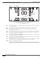
1
C H A P T E R
17
DLPs E100 to E199
Note
The terms "Unidirectional Path Switched Ring" and "UPSR" may appear in Cisco literature. These terms
do not refer to using Cisco ONS 15xxx products in a unidirectional path switched ring configuration.
Rather, these terms, as well as "Path Protected Mesh Network" and "PPMN," refer generally to Cisco's
path protection feature, which may be used in any topological network configuration. Cisco does not
recommend using its path protection feature in any particular topological network configuration.
DLP-E100 Initiate a Force Switch on a Port in a 1+1 Protection Group
Purpose
This task applies the Force external switching command to a 1+1
protection scheme.
Tools/Equipment
Installed OC-N cards
Prerequisite Procedures
DLP-E26 Log into CTC, page 16-33
Required/As Needed
As needed
Onsite/Remote
Onsite or remote
Security Level
Provisioning or higher
Step 1
In node view, click the Maintenance > Protection tabs.
Step 2
In the Protection Group area, select the protection group with the port you want to switch.
In the Selected Group area, each port is identified as Working or Protect. Each port also has a status:
•
Active—The port is carrying traffic.
•
Standby—The port is not carrying traffic.
•
[MANUAL TO WORKING]—A Manual switch has moved traffic to the working port.
•
[MANUAL TO PROTECT]—A Manual switch has moved traffic to the protect port.
•
[FORCE TO WORKING]—A Force switch has moved traffic to the working port.
•
[FORCE TO PROTECT]—A Force switch has moved traffic to the protect port.
The normal status is for one port to be Working/Active and the other to be Protect/Standby.
Step 3
In the Selected Group area, select the port that you want to switch. For example, if you want to switch
traffic from the working port to the protect port, click the working port.
Step 4
Click Force.
Cisco ONS 15600 Procedure Guide, R8.0
17-1
Chapter 17 DLPs E100 to E199
DLP- E101 Apply a Lock On in a 1+1 Group
If the Force switch is successful, CTC shows both ports as [FORCE TO PROTECT] (or
[FORCE TO WORKING]). This indication is shown whether or not the ONS 15600 system has been
able to move traffic from one port to the other.
If the Bidirectional switching check box is checked, both the near-end and far-end nodes switch to the
designated protection ports. For example, if the near-end node has a loss of signal (LOS), it switches to
the protection port and transmits a switch request to the far-end node to switch to the protection port also.
This ensures that both nodes process traffic from the same span.
If the Bidirectional switching check box is not selected, the near-end and far-end nodes switch
independently of each other. For example, if the near-end node has an LOS on its working port, it
switches to the protection port. If the far-end node does not have a LOS, traffic remains on the working
port.
If the Force switch is unsuccessful, clear the switch immediately using the “DLP-E167 Clear a Manual
or Force Switch in a 1+1 Protection Group” task on page 17-53, and then troubleshoot the problems
preventing the switch by referring to the Cisco ONS 15600 Troubleshooting Guide.
Step 5
Click the Conditions tab and click Retrieve to see new events. The switch procedure raises a
FORCED-REQ-SPAN condition that is visible in the window unless Not Alarmed conditions have been
filtered out from the view.
Step 6
Click the Alarms tab.
No new traffic loss alarms or failure-to-switch alarms should appear.
Step 7
Return to your originating procedure (NTP).
DLP-E101 Apply a Lock On in a 1+1 Group
Note
Purpose
This task locks traffic onto a working port to prevent traffic from
switching to the protect port in a protection group.
Tools/Equipment
None
Prerequisite Procedures
DLP-E26 Log into CTC, page 16-33
Required/As Needed
As needed
Onsite/Remote
Onsite or remote
Security Level
Provisioning or higher
A lock on can be applied to a working port only.
Step 1
In node view, click the Maintenance > Protection tabs.
Step 2
In the Protection Groups area, select the protection group where you want to apply a lock on.
Step 3
If you determine that the protect port is in standby and you want to apply the lock on to the protect port,
make the protect port active:
a.
In the Selected Group field, click the protect port.
b.
In the Switch Commands field, click Force.
Step 4
In the Selected Group area, choose the active port where you want to lock on traffic.
Step 5
In the Inhibit Switching field, click Lock On.
Cisco ONS 15600 Procedure Guide, R8.0
17-2
Chapter 17 DLPs E100 to E199
DLP- E102 Apply a Lockout in a 1+1 Group
Step 6
Click Yes in the confirmation dialog box.
The lock on has been applied and traffic cannot be switched from that port. See the “DLP-E168 Clear a
Lock On or Lockout in a 1+1 Protection Group” task on page 17-53 as needed.
Step 7
Return to your originating procedure (NTP).
DLP-E102 Apply a Lockout in a 1+1 Group
Note
Purpose
This task locks traffic out of a protect port in a 1+1 protection group,
which prevents traffic from switching to that port.
Tools/Equipment
None
Prerequisite Procedures
DLP-E26 Log into CTC, page 16-33
Required/As Needed
As needed
Onsite/Remote
Onsite or remote
Security Level
Provisioning or higher
A Lock Out can be applied to a protect port only.
Step 1
In node view, click the Maintenance > Protection tabs.
Step 2
In the Protection Groups field, click the protection group that contains the card you want to lock out.
Step 3
In the Selected Group area, select the card you want to lock out.
Step 4
In the Inhibit Switching field, click Lock Out.
Step 5
Click Yes on the confirmation dialog box.
The lock out has been applied and traffic is switched to the opposite card. To clear the lockout, see the
“DLP-E168 Clear a Lock On or Lockout in a 1+1 Protection Group” task on page 17-53.
Step 6
Return to your originating procedure (NTP).
DLP-E103 Initiate a Manual Switch on a Path Protection Circuit
Step 1
Purpose
This task switches traffic to the path protectionusing a Manual switch.
A Manual switch will switch traffic if the path has an error rate less than
the signal degrade.
Tools/Equipment
None
Prerequisite Procedures
DLP-E26 Log into CTC, page 16-33
Required/As Needed
As needed
Onsite/Remote
Onsite or remote
Security Level
Provisioning or higher
In node view, click the Circuits > Circuits tabs.
Cisco ONS 15600 Procedure Guide, R8.0
17-3
Chapter 17 DLPs E100 to E199
DLP- E104 Initiate a Force Switch to a Path Protection Circuit
Step 2
Click the path you want to switch and then click Edit.
Step 3
In the Edit Circuit window, click the Path Protection Selectors tab.
Step 4
In the Switch State column, click the row for the path you want to switch and select Manual to Protect
or Manual to Working as appropriate.
Step 5
Click Apply.
Step 6
To verify that the switch has occurred, view the Path Protection Selectors tab Switch State column. The
row for the circuit you switched will show a MANUAL status.
Traffic switches from the working path protection to the protect path. If the path is configured for
revertive switching, the traffic reverts to the working path when the Manual switch is cleared. See the
“DLP-E170 Clear a Switch or Lockout on a Path Protection Circuit” task on page 17-55 as needed.
Step 7
Return to your originating procedure (NTP).
DLP-E104 Initiate a Force Switch to a Path Protection Circuit
Purpose
This task switches traffic to the working path protection circuit using a
Force switch. A Force switch will switch traffic even if the path has
signal degrade (SD) or signal fail (SF) conditions. A Force switch has a
higher priority than a Manual switch.
Tools/Equipment
None
Prerequisite Procedures
DLP-E26 Log into CTC, page 16-33
Required/As Needed
As needed
Onsite/Remote
Onsite or remote
Security Level
Provisioning or higher
Step 1
In node view, click the Circuits > Circuits tabs.
Step 2
Click the path you want to switch and click Edit.
Step 3
In the Edit Circuit window, click the Path Protection Selectors tab.
Step 4
In the Switch State column, click the row for the path you want to switch and select Force to Working
or Force to Protect as appropriate.
Step 5
Click Apply.
Step 6
To verify that the switch has occurred, view the Path Protection Selectors tab Switch State column. The
circuit row shows a FORCE status.
Traffic switches from the protect path to the working path. Protection switching cannot occur until the
Force switch is cleared. See the “DLP-E170 Clear a Switch or Lockout on a Path Protection Circuit” task
on page 17-55 as needed.
Step 7
Return to your originating procedure (NTP).
Cisco ONS 15600 Procedure Guide, R8.0
17-4
Chapter 17 DLPs E100 to E199
DLP- E105 Create a DCC Tunnel
DLP-E105 Create a DCC Tunnel
Purpose
This task creates a data communications channel (DCC) tunnel to transport
traffic from third-party SONET equipment across ONS 15600 networks.
Tunnels can be created on the Section DCC (SDCC) channel (D1-D3) (if
not used by a node as a terminated DCC), or any Line DCC (LDCC)
channel (D4-D6, D7-D9, or D10-D12).
Tools/Equipment
None
Prerequisite Procedures NTP-E32 Verify Node Turn-Up, page 5-2
NTP-E128 Modify or Delete Communications Channel Terminations, page
11-8, as needed
Note
Required/As Needed
As needed
Onsite/Remote
Onsite or remote
Security Level
Provisioning or higher
The ONS 15600 can support up to 64 DCC tunnels. Terminated SDCCs cannot be used as a DCC tunnel
endpoint, and an SDCC that is used as a DCC tunnel endpoint cannot be terminated. You must delete the
terminated SDCCs in a path before creating a DCC tunnel. All DCC tunnel connections are bidirectional.
Step 1
In network view, click the Provisioning > Overhead Circuits tabs.
Step 2
Click Create.
Step 3
In the Circuit Creation dialog box, provision the DCC tunnel:
•
Name—Type the tunnel name.
•
Type—Choose one:
– DCC Tunnel - D1-D3—Allows you to choose either the Section DCC (D1-D3) or a Line DCC
(D4-D6, D7-D9, or D10-D12) as the source or destination endpoints.
– DCC Tunnel - D4-D12—Provisions the full Line DCC as a tunnel.
Note
Step 4
DCC Tunnel - D4-D12 type is not supported on ONS 15600. Use the DCC tunneling functionality if the
network has nodes other than ONS 15600, and you do not want the tunnel to go through ONS 15600.
In the Source area, complete the following:
•
Node—Choose the source node.
•
Slot—Choose the source slot.
•
Port—Choose the source port.
•
Channel—Shown if you chose DCC Tunnel-D1-D3 as the tunnel type. Choose one of the following:
– DCC1 (D1-D3)—Section DCC
– DCC2 (D4-D6)—Line DCC 1
– DCC3 (D7-D9)—Line DCC 2
– DCC4 (D10-D12)—Line DCC 3
DCC options do not appear if they are used by the ONS 15600 (DCC1) or other tunnels.
Cisco ONS 15600 Procedure Guide, R8.0
17-5
Chapter 17 DLPs E100 to E199
DLP- E106 Clean Fiber Connectors
Step 5
In the Destination area, complete the following:
•
Node—Choose the destination node.
•
Slot—Choose the destination slot.
•
Port—Choose the destination port.
•
Channel—Shown if you chose DCC Tunnel-D1-D3 as the tunnel type. Choose one of the following:
– DCC1 (D1-D3)—Section DCC
– DCC2 (D4-D6)—Line DCC 1
– DCC3 (D7-D9)—Line DCC 2
– DCC4 (D10-D12)—Line DCC 3
DCC options do not appear if they are used by the ONS 15600 (DCC1) or other tunnels.
Step 6
Click Finish.
Step 7
Put the ports that are hosting the DCC tunnel in service. See the “DLP-E115 Change the Service State
for a Port” task on page 17-16 for instructions.
Step 8
Return to your originating procedure (NTP).
DLP-E106 Clean Fiber Connectors
Purpose
This task cleans the fiber connectors.
Tools/Equipment
Inspection microscope (suggested: Westover FBP-CIS-1)
Desktop hand tool
Scrub tool
3M high-performance fiber-optic wipes
Compressed air/duster
Note
Prerequisite Procedures
None
Required/As Needed
Required
Onsite/Remote
Onsite
Security Level
None
Replace all dust caps whenever the equipment will be unused for 30 minutes or more.
Step 1
Remove the dust cap from the fiber connector.
Step 2
To use the desktop hand tool:
a.
Advance the 3M high-performance fiber-optic wipe in the desktop hand tool to access the unused
wipe area.
Note
To replace the fiber-optic wipe in the desktop hand tool, remove the frame cover. Put a new
wipe over the base of the desktop hand tool with the stitching of the wipe aligned lengthwise
with the tool. Place the frame cover on the tool and press firmly to reattach.
Cisco ONS 15600 Procedure Guide, R8.0
17-6
Chapter 17 DLPs E100 to E199
DLP- E107 Clean the Fiber Adapters
Step 3
b.
Place the connector tip at the top of the slot at a slight angle. In a single stroke, move the connector
down the wipe without lifting the connector from the wipe. Before lifting the connector from the
wipe, straighten the connector.
c.
Repeat the single stroke motion on each side of the alignment pins to clean the entire connector face.
d.
Blow off any wipe lint left on the fiber connector using the compressed air.
To use the scrub tool:
a.
Connect the grounding strap to the scrub tool and to suitable ground.
b.
Install or replace the scrub wipe in the scrub tool with a new wipe. Avoid handling the wipe
excessively.
c.
Scrub between the alignment pins of the fiber connector, and then wipe around the outside of each
alignment pins.
Step 4
Inspect the connector for cleanliness. Repeat Steps 2 and 3 as necessary.
Step 5
Replace the dust cap on the fiber connector until ready for use.
Step 6
Return to your originating procedure (NTP).
DLP-E107 Clean the Fiber Adapters
Purpose
This task cleans the fiber adapters.
Tools/Equipment
Inspection microscope (suggested: Westover FBP-CIS-1)
Scrub tool
Grounding strap
Wipes
Rinse tool
HFE-based cleaning fluid and pump head assembly
Replacement scrub tool wipes
Replacement rinse tool absorbent pads
Empty disposable container
Prerequisite Procedures
None
Required/As Needed
Required
Onsite/Remote
Onsite
Security Level
None
Step 1
Remove the dust plugs from the fiber adapter.
Step 2
To remove stubborn particles from the fiber adapter:
a.
Connect the grounding strap to the scrub tool and to suitable ground.
b.
Install or replace the scrub wipe in the scrub tool with a new wipe. Avoid handling the wipe
excessively.
c.
Insert the scrub tool tip into the fiber adapter.
Cisco ONS 15600 Procedure Guide, R8.0
17-7
Chapter 17 DLPs E100 to E199
DLP- E108 Verify that a 1+1 Working Port is Active
d.
Step 3
Remove and insert the scrub tool tip several times to clean the fiber adapter.
To remove loose particles from the fiber adapter:
a.
Remove the dust cap from the rinse tool.
Note
If the absorbent pad on the rinse tool needs replacement, slide the old pad and mesh retainer
off of the rinse tool tube. Slide the new absorbent pad and mesh retainer over the rinse tip
onto the rinse tool tube. Roll the absorbent pad and mesh retainer between your hands until
the opening on the absorbent pad is closed. Discard the old absorbent pad and mesh retainer.
b.
Connect the grounding strap to the rinse tool and to suitable ground.
c.
Connect the rinse tool to the HFE-based cleaning fluid bottle and pump head assembly.
d.
Turn the aluminum nozzle on the pump one-half turn counterclockwise and squirt the cleaning fluid
into an empty container to soak the rinse tool.
e.
Remove the dust cover from the fiber adapter.
f.
Insert the rinse tool tip into the fiber adapter with the bent part of the handle pointing downwards.
Squirt twice.
g.
Remove the rinse tool and replace the dust cover on the adapter. Replace the dust cap on the rinse
tool.
h.
Turn the aluminum nozzle on the pump clockwise until it is tight and disconnect the HFE bottle from
the pump.
Step 4
Inspect the fiber adapter to ensure it is clean. If it is not clean, repeat Steps 2 and 3.
Step 5
Replace the dust plug in the fiber adapter until ready for use.
Step 6
Return to your originating procedure (NTP).
DLP-E108 Verify that a 1+1 Working Port is Active
Purpose
This task verifies that a working slot in a 1+1 protection scheme is active
(and that the protect slot is in standby).
Tools/Equipment
None
Prerequisite Procedures
DLP-E26 Log into CTC, page 16-33
Required/As Needed
As needed
Onsite/Remote
Both
Security Level
Maintenance or higher
Step 1
In node view, click the Maintenance > Protection tabs.
Step 2
In the Selected Group area, verify that the working slot/port is shown as Working/Active. If so, this task
is complete.
Step 3
If the working slot says Working/Standby, perform a Manual switch on the working port:
a.
In the Selected Group area, choose the Protect/Active port.
b.
In the Switch Commands field, choose Manual.
Cisco ONS 15600 Procedure Guide, R8.0
17-8
Chapter 17 DLPs E100 to E199
DLP- E109 Drill Holes to Anchor and Provide Access to the Bay Assembly
c.
Step 4
Verify that the working slot is carrying traffic (Working/Active).
Note
Step 5
Click Yes in the confirmation dialog box.
If the slot is not active, look for conditions or alarms that might be preventing the card from
carrying working traffic. Refer to the Cisco ONS 15600 Troubleshooting Guide for procedures
to clear alarms.
When the working port is carrying traffic, clear the Manual switch:
a.
In the Switch Commands field, choose Clear.
b.
Click Yes in the confirmation dialog box.
Step 6
Verify that the working port does not revert to Standby, which might indicate a problem on the working
span.
Step 7
Return to your originating procedure (NTP).
DLP-E109 Drill Holes to Anchor and Provide Access to the Bay Assembly
Purpose
This procedure describes how to use the floor template to locate and drill
the appropriate holes that are needed to anchor and provide additional
access to the bay assembly at your site.
Tools/Equipment
Floor template (53-2141-XX)
Marking pen
Concrete drill
Reciprocating saw
Prerequisite Procedures NTP-E1 Unpack and Inspect the ONS 15600 Bay Assembly, page 1-4
Note
Step 1
Required/As Needed
Required
Onsite/Remote
Onsite
Security Level
None
If the bay will use wide cable routing modules (CRMs) for cable routing, you need to use 900-mm
(35.4-in) spacing between bays.
Determine the proper location of your bay:
a.
For a 900-mm (35.4-inch) wide bay, position the floor template so that corner indicators “B” fall
where you want the corners of the bay to reside (Figure 17-1).
b.
For a 600-mm (23.6-inch) wide bay, position the floor template so that corner indicators “A” fall
where you want the corners of the bay to reside (Figure 17-1).
Note
If space allows, Cisco recommends you reserve an additional 1/4 inch (6.35 mm) of space
on each side of the bay assembly you are installing.
Cisco ONS 15600 Procedure Guide, R8.0
17-9
Chapter 17 DLPs E100 to E199
DLP- E109 Drill Holes to Anchor and Provide Access to the Bay Assembly
Figure 17-1
Floor Template
A
A
UNDERFLOOR CMP CABLE
C
B
OPTICAL CABLE ACCESS
G
F
H
UNDERFLOOR CMP CABLE
D
B
G
H
C
F
D
OPTICAL CABLE ACCESS
E
UNDERFLOOR SYSTEM CABLE
H
E
H
UNDERFLOOR SYSTEM CABLE
Bolt Hole
Pattern
UNDERFLOOR POWER
UNDERFLOOR POWER
UNDERFLOOR NETWORK CABLE
UNDERFLOOR NETWORK CABLE
OPTICAL CABLE ACCESS
C
CABLE ROUTING MODULE
B
J
J
F
A
H
H
D
FRONT
D
F
A
CABLE ROUTING MODULE
B
ADJACENT RACK
C
83488
ADJACENT RACK
600 mm Footprint
900 mm Footprint
Adjacent Rack
Step 2
Use the corner indicators “C” to determine the closest recommended position of an adjacent 900-mm
(35.4-inch) bay assembly.
Step 3
Use a marking pen to mark the floor with the corner indicators appropriate to your installation.
Step 4
At the four locations marked “D,” drill floor bolt holes according to the bolt manufacturer’s
recommendation for bolt hole size.
Step 5
If you will use under-floor power, use the drill and saw to cut out the rectangular floor areas marked “E.”
Step 6
If you will route optical cables in a 900-mm (35.4-inch) bay from under the floor, use the drill and saw
to cut out the rectangular floor areas marked “F.”
Step 7
If you will route optical cables in a 600-mm (23.6-inch) bay from under the floor, use the drill and saw
to cut out the rectangular floor areas marked “J.”
Step 8
If you will route any timing, alarm, or LAN cables through the floor to the customer access panel (CAP),
use the drill to cut out the floor areas marked “G.”
Step 9
(Optional.) If you want to create other access holes for under-floor access (for AC power, for example),
use the reciprocating saw to cut sufficient holes within any of the locations marked “H.”
Step 10
Return to your originating procedure (NTP).
Cisco ONS 15600 Procedure Guide, R8.0
17-10
Chapter 17 DLPs E100 to E199
DLP- E110 Assign a Name to a Port
DLP-E110 Assign a Name to a Port
Purpose
This task assigns a name to a port on any ONS 15600 card.
Tools/Equipment
None
Prerequisite Procedures DLP-E26 Log into CTC, page 16-33
NTP-E21 Verify Card Installation, page 4-2
Required/As Needed
As needed
Onsite/Remote
Onsite or remote
Security Level
Provisioning or higher
Step 1
Double-click the card that has the port you want to provision.
Step 2
Click the Provisioning tab.
Step 3
Click the Port Name column for the port number you are assigning a name to and enter the desired port
name.
The port name can be up to 32 alphanumeric/special characters and is blank by default.
Step 4
Click Apply.
Step 5
Return to your originating procedure (NTP).
DLP-E111 Provision Path Protection Selectors During Circuit Creation
Purpose
This task provisions path protection selectors during circuit creation. Use
this task only if the circuit will be routed on a path protection.
Tools/Equipment
None
Prerequisite Procedures You must have the Circuit Creation wizard open.
Note
Step 1
Required/As Needed
As needed
Onsite/Remote
Onsite or remote
Security Level
Provisioning or higher
Provisioning signal degrade–path (SD-P) or signal fail–path (SF-P) thresholds in the Circuit Attributes
page of the Circuit Creation wizard sets the values only for path protection-protected spans. The circuit
source and destination use the node default values of 10E-4 for SD-P and 10E-6 for SF-P for unprotected
circuits and for the source and drop of path protection circuits.
In the Circuit Attributes area of the Circuit Creation wizard, set the path protection path selectors:
•
Provision working go and return on primary path—Check this box to route the working path on one
fiber pair and the protect path on a separate fiber pair. This feature only applies to bidirectional path
protection circuits.
•
Revertive—Check this box if you want traffic to revert to the working path when the conditions that
diverted it to the protect path are repaired. If you do not choose Revertive, traffic remains on the
protect path after the switch.
Cisco ONS 15600 Procedure Guide, R8.0
17-11
Chapter 17 DLPs E100 to E199
DLP- E112 Provision a Half Circuit Source and Destination on a BLSR or 1+1
Step 2
•
Reversion time—If Revertive is checked, click the Reversion time field and choose a reversion time
from the drop-down list. The range is 0.5 to 12.0 minutes. The default is 5.0 minutes. This is the
amount of time that will elapse before the traffic reverts to the working path. Traffic can revert when
conditions causing the switch are cleared.
•
SF threshold—For STS circuits, set the path protection path-level signal failure bit error rate (BER)
thresholds.
•
SD threshold—For STS circuits, set the path protection path-level signal degrade BER thresholds.
•
Switch on PDI-P—For STS circuits, check this box if you want traffic to switch when an STS
payload defect indication–path is received.
Return to your originating procedure (NTP).
DLP-E112 Provision a Half Circuit Source and Destination on a BLSR or 1+1
Purpose
This task provisions a half circuit source and destination for bidirectional
line switched rings (BLSRs) and 1+1 protection.
Tools/Equipment
None
Prerequisite Procedures NTP-E82 Create a Half Circuit on a BLSR or 1+1 Node, page 6-18
Required/As Needed
As needed
Onsite/Remote
Onsite or remote
Security Level
Provisioning or higher
Step 1
From the Node drop-down list, choose the node that will contain the half circuit.
Step 2
From the Slot drop-down list, choose the slot containing the card where the circuit will originate.
Step 3
From the Port drop-down list, choose the port where the circuit will originate.
Step 4
Click Next.
Step 5
From the Node drop-down list, choose the node chosen in Step 1.
Step 6
From the Slot drop-down list, choose the OC-N card to map the OC-N STS circuit to an synchronized
transport signal (STS).
Step 7
Choose the destination STS from the additional drop-down lists that appear based on your choices.
Step 8
Return to your originating procedure (NTP).
Cisco ONS 15600 Procedure Guide, R8.0
17-12
Chapter 17 DLPs E100 to E199
DLP- E113 Provision a Half Circuit Source and Destination on a Path Protection
DLP-E113 Provision a Half Circuit Source and Destination on a Path Protection
Purpose
This task provisions a half circuit source and destination for a path
protection. This task is used to create path protection selectors on the node.
Depending on the specific network configuration, the path protection
selector can be created on the source side (two sources, one destination);
the destination side (one source, two destinations); or both (two sources,
two destinations). Selectors are required on both the source and destination
sides when two STS path protection paths (rings) are interconnected at a
single node.
Tools/Equipment
None
Prerequisite Procedures NTP-E83 Create a Half Circuit on a Path Protection Node, page 6-20
The Source page of the Circuit Creation wizard must be open.
Required/As Needed
As needed
Onsite/Remote
Onsite or remote
Security Level
Provisioning or higher
Step 1
From the Node drop-down list, choose the node that will contain the half circuit.
Step 2
From the Slot drop-down list, choose the slot containing the card where the circuit will originate.
Step 3
From the Port drop-down list, choose the port where the circuit will originate.
Step 4
If applicable, choose the source STS.
Step 5
If you want to create a path protection with two sources, click Use Secondary Source and repeat Steps
1 through 4. If not, skip this step and continue with Step 6.
Step 6
Click Next.
Step 7
From the Node drop-down list, choose the node chosen in Step 1.
Step 8
From the Slot drop-down list, choose the destination slot.
Step 9
From the Port drop-down list, choose the destination port.
Step 10
If applicable, choose the destination STS.
Step 11
If you want to create a path protection with two destinations, click Use Secondary Destination and
repeat Steps 7 through 10.
Step 12
Return to your originating procedure (NTP).
Cisco ONS 15600 Procedure Guide, R8.0
17-13
Chapter 17 DLPs E100 to E199
DLP- E114 Provision Section DCC Terminations
DLP-E114 Provision Section DCC Terminations
Purpose
This task creates SONET Section DCC terminations required for alarms,
administration data, signal control information, and messages.
Tools/Equipment
None
Prerequisite Procedures DLP-E26 Log into CTC, page 16-33
Required/As Needed
As needed
Onsite/Remote
Onsite or remote
Security Level
Provisioning or higher
Step 1
In node view, click the Provisioning > Comm Channels > SDCC tabs.
Step 2
In the SDCC Terminations area, click Create.
Step 3
In the Create SDCC Terminations dialog box, click the ports where you want to create the DCC
termination. To select more than one port, press the Shift key or the Ctrl key.
Note
SDCC refers to the Section DCC, which is used for ONS 15600 DCC terminations. You can
provision the SONET Line DCCs and SDCCs (when not used as a DCC termination by the
ONS 15600) as DCC tunnels. See the “DLP-E105 Create a DCC Tunnel” task on page 17-5. You
can provision SDCC and Line DCC on the same port but it is not recommend. SDCC and Line
DCC are only needed on the same port during a software upgrade if the software version does
not support SDCC. Provision Line DCC termination on the port that already has SDCC see
“DLP-E189 Provision Line DCC Terminations” task on page 17-70. Delete SDCC provisioned
on that port, see “DLP-E198 Delete a Section DCC Termination” task on page 17-76. Enable
OSPF on the Line DCC termination if not enabled see “DLP-E197 Change a Line DCC
Termination” task on page 17-75.
Step 4
In the Port Admin State area, click Set to IS to put the port in service.
Step 5
Verify that the Disable OSPF on SDCC Link is unchecked.
Step 6
If the SDCC termination is to include a non-ONS node, check the Far End is Foreign check box. This
automatically sets the far-end node IP address to 0.0.0.0, which means that any address can be specified
by the far end. To change the default to a specific the IP address, see the “DLP-E196 Change a Section
DCC Termination” task on page 17-75.
Step 7
In the Layer 3 box, perform one of the following:
•
Check the IP box only—if the SDCC is between the ONS 15600 and another ONS node and only
ONS nodes reside on the network. The SDCC will use PPP (point-to-point protocol).
•
Check the IP and OSI boxes—if the SDCC is between the ONS 15600 and another ONS node and
third party NEs that use the Open System Interconnection (OSI) protocol stack are on the same
network. The SDCC will use PPP.
•
Check OSI box only—if the SDCC is between an ONS node and a third party NE that uses the OSI
protocol stack. The SDCC will use the LAP-D protocol.
Note
If OSI is checked and IP is not checked (LAP-D), no network connections will appear in
network view.
Cisco ONS 15600 Procedure Guide, R8.0
17-14
Chapter 17 DLPs E100 to E199
DLP- E114 Provision Section DCC Terminations
Step 8
If you checked OSI, complete the following steps. If you checked IP only, continue with Step 9.
a.
Click Next.
b.
Provision the following fields:
– Router—Choose the OSI router.
– ESH—Sets the End System Hello (ESH) propagation frequency. End system NEs transmit
ESHs to inform other ESs and ISs about the NSAPs it serves. The default is 10 seconds. The
range is 10 to 1000 seconds.
– ISH—Sets the Intermediate System Hello (ISH) PDU propagation frequency. Intermediate
system NEs send ISHs to other ESs and ISs to inform them about the IS NETs it serves. The
default is 10 seconds. The range is 10 to 1000 seconds.
– IIH—Sets the Intermediate System to Intermediate System Hello (IIH) PDU propagation
frequency. The IS-IS Hello PDUs establish and maintain adjacencies between ISs. The default
is 3 seconds. The range is 1 to 600 seconds.
– IS-IS Cost—Sets the cost for sending packets on the LAN subnet. The IS-IS protocol uses the
cost to calculate the shortest routing path. The default metric cost for LAN subnets is 20. It
normally should not be changed.
– Default button—If clicked, sets the default values for the Router, ESH, ISH, IIH, and IS-IS Cost
fields.
c.
If the OSI and IP boxes are checked, continue with Step 9. If only the OSI is checked, click Next
and provision the following fields:
– Mode
AITS—(Acknowledged Information Transfer Service) (Default) Does not exchange data until
a logical connection between two LAP-D users is established. This service provides reliable
data transfer, flow control, and error control mechanisms.
UITS—(Unacknowledged Information Transfer Service) Transfers frames containing user data
with no acknowledgement. The service does not guarantee that the data presented by one user
will be delivered to another user, nor does it inform the user if the delivery attempt fails. It does
not provide any flow control or error control mechanisms.
– Role—Set to the opposite of the mode of the NE at the other end of the SDCC.
– MTU (Maximum transmission unit)—Sets the maximum number of octets in a LAP-D
information frame. The range is 512 to 1500 octets. The default is 512. You normally should not
change it.
– T200— Sets the time between Set Asynchronous Balanced Mode (SABME) frame
retransmissions. The default is 0.2 seconds. The range is 0.2 to 20 seconds.
– T203—Provisions the maximum time between frame exchanges, that is, the trigger for
transmission of the LAP-D “keep-alive” Receive Ready (RR) frames. The default is 10 seconds.
The range is 4 to 120 seconds.
Step 9
Click Finish.
Step 10
Return to your originating procedure (NTP).
Cisco ONS 15600 Procedure Guide, R8.0
17-15
Chapter 17 DLPs E100 to E199
DLP- E115 Change the Service State for a Port
DLP-E115 Change the Service State for a Port
Purpose
This task puts a port in service or removes a port from service.
Tools/Equipment
None
Prerequisite Procedures DLP-E26 Log into CTC, page 16-33
Required/As Needed
As needed
Onsite/Remote
Onsite or remote
Security Level
Provisioning or higher
Step 1
In node view, double-click the card with the port(s) you want to put in or out of service. The card view
appears.
Step 2
Click the Provisioning > Line tabs.
Step 3
In the Admin State column for the target port, choose one of the following from the drop-down list:
•
IS—Puts the port in the In-Service and Normal (IS-NR) service state.
•
OOS, DSBLD—Puts the port in the Out-of-Service and Management, Disabled (OOS-MA,DSBLD)
service state. In this service state, traffic is not passed on the port until the service state is changed
to IS-NR; Out-of-Service and Management, Maintenance (OOS-MA,MT); or Out-of-Service and
Autonomous, Automatic In-Service (OOS-AU,AINS).
•
OOS, MT—Puts the port in the OOS-MA,MT service state. This service state does not interrupt
traffic flow and loopbacks are allowed, but alarm reporting is suppressed. Raised fault conditions,
whether or not their alarms are reported, can be retrieved on the CTC Conditions tab or by using the
TL1 RTRV-COND command. Use the OOS-MA,MT service state for testing or to suppress alarms
temporarily. Change to the IS-NR or OOS-AU,AINS service states when testing is complete.
•
IS, AINS—Puts the port in the OOS-AU,AINS service state. In this service state, alarm reporting is
suppressed, but traffic is carried and loopbacks are allowed. After the soak period passes, the port
changes to IS-NR. Raised fault conditions, whether their alarms are reported or not, can be retrieved
on the CTC Conditions tab or by using the TL1 RTRV-COND command.
Note
CTC will not allow you to change a port service state from IS-NR to OOS-MA,DSBLD. You
must first change a port to the OOS-MA,MT service state before putting it in the
OOS-MA,DSBLD service state.
For more information about service states, refer to the “Administrative and Service States” appendix of
the Cisco ONS 15600 Reference Manual.
Step 4
If the port is in loopback (OOS-MA,LPBK & MT) and you set the Admin State to IS, a confirmation
window appears indicating that the loopback will be released and that the action could be service
affecting. To continue, click Yes.
Step 5
If you set the Admin State to IS,AINS, set the soak period time in the AINS Soak field. This is the
amount of time that the port will stay in the OOS-AU,AINS service state after a signal is continuously
received. When the soak period elapses, the port changes to the IS-NR service state.
Step 6
Click Apply.
Step 7
As needed, repeat this task for each port.
Cisco ONS 15600 Procedure Guide, R8.0
17-16
Chapter 17 DLPs E100 to E199
DLP- E116 Remap the K3 Byte
Step 8
Return to your originating procedure (NTP).
DLP-E116 Remap the K3 Byte
Purpose
This task provisions the K3 byte. Do not remap the K3 byte unless
specifically required to run an ONS 15600 BLSR through third-party
equipment. This task is unnecessary for most users.
Tools/Equipment
None
Prerequisite Procedures DLP-E26 Log into CTC, page 16-33
Caution
Required/As Needed
As needed
Onsite/Remote
Onsite
Security Level
Provisioning or higher
If you remap the K3 byte, remap to the same extended byte (Z2, E2, or F1) on either side of the span.
Step 1
In node view, double-click the card that connects to the third-party equipment.
Step 2
Click the Provisioning > Line tabs.
Step 3
Click BLSR Ext Byte and choose the alternate byte: Z2, E2, or F1.
Step 4
Click Apply.
Step 5
Repeat Steps 1 through 4 at the node and card on the other end of the BLSR span.
Note
Step 6
The extension byte set in Step 3 should match at both ends of the span.
Return to your originating procedure (NTP).
DLP-E119 Set Auto-Refresh Interval for Displayed PM Counts
Purpose
This task changes the window auto-refresh intervals for updating the PM
counts.
Tools/Equipment
None
Prerequisite Procedures
DLP-E26 Log into CTC, page 16-33.
Required/As Needed
As needed
Onsite/Remote
Onsite or remote
Security Level
Retrieve or higher
Step 1
In node view, double-click an OC-N card. The card view appears.
Step 2
Click the Performance tab.
Cisco ONS 15600 Procedure Guide, R8.0
17-17
Chapter 17 DLPs E100 to E199
DLP- E120 Remove the Narrow CRMs
Step 3
Step 4
From the Auto-refresh drop-down list choose one of the following options:
•
None: This option disables the auto-refresh feature.
•
15 Seconds: This option sets the window auto-refresh to 15-second time intervals.
•
30 Seconds: This option sets the window auto-refresh to 30-second time intervals.
•
1 Minute: This option sets the window auto-refresh to one-minute time intervals.
•
3 Minutes: This option sets the window auto-refresh to three-minute time intervals.
•
5 Minutes: This option sets the window auto-refresh to five-minute time intervals.
Click Refresh. The PM counts for the new time interval appear.
Depending on the selected auto-refresh interval, the PM counts shown automatically update when each
refresh interval is complete. If the auto-refresh interval is set to None, the PM counts are not updated
unless you click the Refresh button.
Step 5
Return to your originating procedure (NTP).
DLP-E120 Remove the Narrow CRMs
Purpose
This task removes existing narrow CRMs on the ONS 15600 bay so that
you can install the wide CRMs.
Tools/Equipment
Phillips screwdriver, 6 inches long
Retaining screws
Prerequisite Procedures None
Step 1
Required/As Needed
As needed
Onsite/Remote
Onsite
Security Level
None
Use a Phillips screwdriver to loosen the three screws (approximately five revolutions each) on the
existing cable routers (Figure 17-2).
Cisco ONS 15600 Procedure Guide, R8.0
17-18
Chapter 17 DLPs E100 to E199
DLP- E120 Remove the Narrow CRMs
Figure 17-2
Narrow CRMs
Right
narrow
CRM
Left
cable
radius
Right
cable
radius
96608
Left
narrow
CRM
Step 2
Lift the cable router slightly and pull it away from the bay.
Step 3
Repeat this procedure for the router on the other side.
Step 4
Unscrew and remove the cable radius pieces at the lower right and left sides of the shelf.
Step 5
Return to your originating procedure (NTP).
Cisco ONS 15600 Procedure Guide, R8.0
17-19
Chapter 17 DLPs E100 to E199
DLP- E121 Replace the Existing 600-mm Kick Plates with 900-mm Kick Plates
DLP-E121 Replace the Existing 600-mm Kick Plates with 900-mm Kick Plates
Purpose
This task removes the existing 600-mm (23.6-inch) kick plates so you can
install the 900-mm (35.4-inch) kick plates. You should install 900-mm
(35.4-inch) kick plates if you plan to install the wide CRMs.
Tools/Equipment
900-mm kick plate kit (53-2178-XX)
Screwdriver
Retaining screws
Prerequisite Procedures None
Required/As Needed
As needed
Onsite/Remote
Onsite
Security Level
None
Step 1
Using the screwdriver, remove the five screws located on the 600-mm (23.6-inch) kick plate on the front
of the bay.
Step 2
Repeat Step 1 for the kick plate at the rear of the bay.
Step 3
Place a 900-mm (35.4-inch) kick plate (700-16756-XX) at the front of the bay and use a screwdriver to
install the five screws.
Step 4
On the right side of the bay, install the side kick plate (700-16758-XX) using the two appropriate screws.
Note
Make sure the side kick plate’s larger flange is on the floor.
Step 5
Repeat Step 4 for the left and rear kick plates.
Step 6
Return to your originating procedure (NTP).
DLP-E122 Manual Switch the Node Timing Reference
Purpose
This task commands the network element (NE) to switch to the timing
reference you have selected if the synchronization status message (SSM)
quality of the requested reference is not less than the current reference.
Tools/Equipment
None
Prerequisite Procedures
DLP-E26 Log into CTC, page 16-33
Required/As Needed
As needed
Onsite/Remote
Onsite or remote
Security Level
Maintenance or higher
Step 1
In node view, click the Maintenance > Timing > Source tabs. The Timing source window appears.
Step 2
In the Reference drop-down list for the desired Clock, choose the desired reference.
Step 3
In the Operation drop-down list, choose Manual.
Cisco ONS 15600 Procedure Guide, R8.0
17-20
Chapter 17 DLPs E100 to E199
DLP- E123 Clear a Manual Switch on a Node Timing Reference
This operation commands the node to switch to the reference you have selected if the SSM quality of the
reference is not lower than the current timing reference.
Step 4
Click the Apply button.
Step 5
Click Yes in the confirmation dialog box. If the selected timing reference is an acceptable valid
reference, the node switches to the selected timing reference.
Step 6
If the selected timing reference is invalid, a warning dialog box appears. Click OK; the timing reference
does not revert.
Step 7
Return to your originating procedure (NTP).
DLP-E123 Clear a Manual Switch on a Node Timing Reference
Purpose
This task clears a Manual switch on a node timing reference and reverts
the timing reference to its provisioned reference.
Tools/Equipment
None
Prerequisite Procedures
DLP-E26 Log into CTC, page 16-33
Required/As Needed
As needed
Onsite/Remote
Onsite or remote
Security Level
Maintenance or higher
Step 1
In node view, click the Maintenance > Timing > Source tabs. The Timing source window appears.
Step 2
Find the Clock reference that is currently set to Manual in the Operation menu.
Step 3
In the Operation drop-down list, choose Clear.
Step 4
Click the Apply button.
Step 5
Click Yes in the confirmation dialog box. If the normal timing reference is an acceptable valid reference,
the node switches back to the normal timing reference as defined by the system configuration.
Step 6
If the normal timing reference is invalid or has failed, a warning dialog box appears. Click OK; the
timing reference does not revert.
Step 7
Return to your originating procedure (NTP).
Cisco ONS 15600 Procedure Guide, R8.0
17-21
Chapter 17 DLPs E100 to E199
DLP- E124 Set the Optical Power Received Nominal Value
DLP-E124 Set the Optical Power Received Nominal Value
Purpose
This task sets the optical power received (OPR) threshold for each optical
card. The ONS 15600 node uses the value set as a performance monitoring
parameter to determine if the power level has degraded.
Tools/Equipment
None
Prerequisite Procedures DLP-E26 Log into CTC, page 16-33
Required/As Needed
Required
Onsite/Remote
Onsite or remote
Security Level
Provisioning or higher
Step 1
In node view, double-click the OC-N card that you want to provision. The card view appears.
Step 2
Click the Provisioning > SONET Thresholds tabs.
Step 3
From the Types list, choose Physical and click the Refresh button.
Step 4
For Port 1, click the Set button in the Set OPR column. At the confirmation dialog box, click OK.
Step 5
Repeat Step 4 for each port on the card.
Step 6
Repeat this task for each optical card.
Step 7
Return to your originating procedure (NTP).
DLP-E125 Provision the IIOP Listener Port on the ONS 15600
Note
Purpose
This task provisions the IIOP listener port on the ONS 15600, which
enables you to access ONS 15600s that reside behind a firewall.
Tools/Equipment
IIOP listener port number provided by your LAN or firewall administrator
Prerequisite Procedures
DLP-E26 Log into CTC, page 16-33
Required/As Needed
As needed
Onsite/Remote
Onsite or remote
Security Level
Provisioning or higher
If the Enable Proxy Server on port 1080 check box is checked, CTC will use Port 1080 and ignore the
configured IIOP port setting. If Enable Proxy Server is subsequently unchecked, the configured IIOP
listener port is used.
Step 1
Click the Provisioning > Security > Access subtabs.
Step 2
In the TSC CORBA (IIOP) Listener Port area, choose a listener port option:
•
Default - TSC Fixed—Uses Port 57790 to connect to ONS 15600s on the same side of the firewall
or if no firewall is used (default). This option can be used for access through a firewall if Port 57790
is open.
•
Standard Constant—Uses Port 683, the CORBA default port number.
Cisco ONS 15600 Procedure Guide, R8.0
17-22
Chapter 17 DLPs E100 to E199
DLP- E126 Provision the IIOP Listener Port on the CTC Computer
•
Other Constant—If Port 683 is not used, type the IIOP port specified by your firewall administrator.
Step 3
Click Apply.
Step 4
When the Change Network Configuration message appears, click Yes.
Both Timing and Shelf controllers (TSCs) reboot, one at a time. The reboot will take approximately
15 minutes.
Step 5
Return to your originating procedure (NTP).
DLP-E126 Provision the IIOP Listener Port on the CTC Computer
Purpose
This task selects the IIOP listener port on CTC.
Tools/Equipment
IIOP listener port number from LAN or firewall administrator
Prerequisite Procedures
NTP-E21 Verify Card Installation, page 4-2
DLP-E26 Log into CTC, page 16-33
Required/As Needed
Required only if the computer running CTC resides behind a firewall
Onsite/Remote
Onsite or remote
Security Level
Provisioning or higher
Step 1
From the Edit menu, choose Preferences.
Step 2
In the Preferences dialog box, click the Firewall tab.
Step 3
In the CTC CORBA (IIOP) Listener Port area, choose a listener port option:
•
Default - Variable—Use to connect to ONS 15600s from within a firewall or if no firewall is used
(default).
•
Standard Constant—Use Port 683, the CORBA default port number.
•
Other Constant—If Port 683 is not used, enter the IIOP port defined by your administrator.
Step 4
Click Apply. A warning appears telling you that the port change will apply during the next CTC login.
Step 5
Click OK.
Step 6
In the Preferences dialog box, click OK.
Step 7
To access the ONS 15600 using the IIOP port, log out of CTC then log back in. (To log out, choose Exit
from the File menu.)
Step 8
Return to your originating procedure (NTP).
Cisco ONS 15600 Procedure Guide, R8.0
17-23
Chapter 17 DLPs E100 to E199
DLP- E127 Edit Path Protection Circuit Path Selectors
DLP-E127 Edit Path Protection Circuit Path Selectors
Purpose
This task changes the path protection SF and SD thresholds, the reversion
time, and payload defect indication–path (PDI-P) settings.
Tools/Equipment
None
Prerequisite Procedures DLP-E26 Log into CTC, page 16-33
NTP-E35 Provision Path Protection Nodes, page 5-17
Required/As Needed
As needed
Onsite/Remote
Onsite or remote
Security Level
Provisioning or higher
Step 1
Click the Circuits tab.
Step 2
In the Circuits tab, click the path protection circuit that you want to edit. To change the settings for
multiple circuits, press the Shift key (to choose adjoining circuits) or the Ctrl key (to choose
nonadjoining circuits) and click each circuit you want to change.
Step 3
From the Tools menu, choose Circuits > Set Path Selector Attributes.
Note
Step 4
Step 5
Alternatively, for single circuits, you can click the Edit button, then click the path protection
Selectors tab in the Edit Circuits window.
In the Path Selectors Attributes dialog box, edit the following path protection selectors, as needed:
•
Revertive—If checked, traffic reverts to the working path when conditions that diverted it to the
protect path are repaired. If not checked, traffic does not revert.
•
Reversion Time (Min)—If Revertive is checked, sets the amount of time that will elapse before
traffic reverts to the working path. The range is 0.5 to 12 minutes in 0.5 minute increments.
In the STS Circuits Only area, set the following thresholds:
•
SF Ber Level—(STS circuits only.) Sets the path protection signal failure BER threshold.
•
SD Ber Level—(STS circuits only.) Sets the path protection signal degrade BER threshold.
•
PDI-P—(STS circuits only.) When checked, traffic switches if an STS payload defect indication is
received.
Step 6
Click OK and verify that the changed values are correct.
Step 7
Return to your originating procedure (NTP).
Cisco ONS 15600 Procedure Guide, R8.0
17-24
Chapter 17 DLPs E100 to E199
DLP- E128 Change the Node Name, Date, Time, and Contact Information
DLP-E128 Change the Node Name, Date, Time, and Contact Information
Purpose
This task changes basic node information such as node name, date, time,
and contact information.
Tools/Equipment
None
Prerequisite Procedures DLP-E26 Log into CTC, page 16-33
Note
Required/As Needed
As needed
Onsite/Remote
Onsite or remote
Security Level
Provisioning or higher
Changing the date, time, or time zone might invalidate node performance monitoring counters.
Step 1
In node view, click the Provisioning > General tabs.
Step 2
Change any of the following:
•
General: Node Name
•
General: Contact
•
Location: Latitude
•
Location: Longitude
•
Location: Description
Note
To see changes to longitude or latitude on the network map, you must go to network view
and right-click the specified node, then click Reset Node Position.
•
Time: Use SNTP Server
•
Time: Date (M/D/Y)
•
Time: Time (H:M:S)
•
Time: Time Zone
•
Time: Use Daylight Saving Time
See the “NTP-E22 Set Up Date, Time, and Contact Information” procedure on page 4-4 for detailed field
descriptions.
Step 3
Click Apply. Confirm that the changes appear; if not, repeat the task.
Step 4
Return to your originating procedure (NTP).
Cisco ONS 15600 Procedure Guide, R8.0
17-25
Chapter 17 DLPs E100 to E199
DLP- E129 Enable Dialog Box Do-Not-Display Option
DLP-E129 Enable Dialog Box Do-Not-Display Option
Purpose
This task enables or disables the “Do not show this dialog again” dialog box
preference for subsequent sessions or disables the do not display option.
Tools/Equipment
None
Prerequisite procedures DLP-E26 Log into CTC, page 16-33
Note
Required/As needed
As needed
Onsite/Remote
Onsite or remote
Security Level
Provisioning or higher
If any user who has rights to perform an operation (for example, creating a circuit) selects the “Do not
show this dialog again” check box on a dialog box, the dialog box is not displayed for any other users
who perform that operation on the network unless the command is overridden using the following task.
Step 1
From the Edit menu, choose Preferences.
Step 2
In the Preferences dialog box, click the General tab.
The Preferences Management area field lists all dialog boxes where “Do not show this dialog again” was
checked.
Step 3
Choose one of the following:
•
Don’t Show Any—Hides all do-not-display check boxes.
•
Show All—Overrides do-not-display check box selections and displays all dialog boxes.
Step 4
Click OK.
Step 5
Return to your originating procedure (NTP).
DLP-E130 Change Security Policy on a Single Node
Purpose
This task changes the security policy for a single node, including idle user
timeouts, user lockouts, password changes, and concurrent login policies.
Tools/Equipment
None
Prerequisite Procedures DLP-E26 Log into CTC, page 16-33
Required/As Needed
As needed
Onsite/Remote
Onsite or remote
Security Level
Superuser
Step 1
In node view, click the Provisioning > Security > Policy tabs.
Step 2
In the Idle User Timeout area, you can modify the timeout times for each security level by clicking the
hour (H) and minute (M) arrows. You can choose values between 0 and 16 hours and 0 and 59 minutes.
Cisco ONS 15600 Procedure Guide, R8.0
17-26
Chapter 17 DLPs E100 to E199
DLP- E131 Change Security Policy on Multiple Nodes
Step 3
Step 4
In the User Lockout area, you can modify the following:
•
Failed Logins Before Lockout—Choose the number of failed login attempts a user can make before
the user is locked out from the node. You can choose a value between 0 and 10.
•
Manual Unlock by Superuser—Check this box if you want to allow a user with Superuser privileges
to manually unlock a user who has been locked out from a node. The user will remain locked out
until a Superuser manually unlocks the user.
•
Lockout Duration—Choose the amount of time the user will be locked out after a failed login. You
can choose a value between 0 and 10 minutes, and 0 and 55 seconds (in five-second intervals).
In the Password Change area, you can modify the following:
•
Require [nn] different passwords...—Choose a value between 0 and 10 to determine how many
different passwords have to be created before a password can be reused.
•
...or a waiting period of [nn] days before password reuse—Choose a value between 0 and 30 days
to set the amount of time (in days) before a password can be reused.
Note
“Require [nn] different passwords or a waiting period of [nn] days before password reuse” is an
OR statement, meaning that either one of the two conditions that you set can be satisfied for a
password to be reused.
Step 5
In the Concurrent Logins area, click Single Session Per User if you want to limit users to a single login
session.
Step 6
Click Apply. Confirm that the changes appear; if not, repeat the task.
Step 7
Return to your originating procedure (NTP).
DLP-E131 Change Security Policy on Multiple Nodes
Purpose
This task changes the security policy for multiple nodes including idle user
timeouts, user lockouts, password change, and concurrent login policies.
Tools/Equipment
None
Prerequisite Procedures DLP-E26 Log into CTC, page 16-33
Required/As Needed
As needed
Onsite/Remote
Onsite or remote
Security Level
Superuser
Step 1
From the View menu, choose Go To Network View.
Step 2
Click the Provisioning > Security > Policy tabs. A read-only table of nodes and their policies appears.
Step 3
Click a node on the table that you want to modify, then click Change.
Step 4
In the Idle User Timeout area, you can modify the timeout times for each security level by clicking the
hour (H) and minute (M) arrows. You can choose values between 0 and 16 hours and 0 and 59 minutes.
Step 5
In the User Lockout area, you can modify the following:
•
Failed Logins Before Lockout—Choose the number failed login attempts a user can make before the
user is locked out from the node. You can choose a value between 0 and 10.
Cisco ONS 15600 Procedure Guide, R8.0
17-27
Chapter 17 DLPs E100 to E199
DLP- E132 Change User Password and Security Levels for a Single Node
Step 6
•
Manual Unlock by Superuser—Check this box if you want to allow a user with Superuser privileges
to manually unlock a user who has been locked out from a node. The user will remain locked out
until a Superuser manually unlocks the user.
•
Lockout Duration—Choose the amount of time the user will be locked out after a failed login. You
can choose a value between 0 and 10 minutes, and 0 and 55 seconds (in five-second intervals).
In the Password Change area, you can modify the following:
•
Require [nn] different passwords...—Choose the number of different passwords that have to be
created before a password can be reused. You can choose a value between 0 and 10 days.
•
...or a waiting period of [nn] days before password reuse—Choose the number of days the user must
wait before reusing a password. You can choose a value between 0 and 30 days.
Note
“Require [nn] different passwords or a waiting period of [nn] days before password reuse” is an
OR statement, meaning that either one of the two conditions you set can be satisfied for a
password to be reused.
Step 7
In the Concurrent Logins area, click Single Session Per User if you want to limit users to a single login
session.
Step 8
Click OK. The Security Policy Change Results dialog box appears.
Step 9
Confirm that the changes are correct and click OK.
Step 10
Return to your originating procedure (NTP).
DLP-E132 Change User Password and Security Levels for a Single Node
Purpose
This task changes settings for an existing user at one node.
Tools/Equipment
None
Prerequisite Procedures DLP-E26 Log into CTC, page 16-33
Required/As Needed
As needed
Onsite/Remote
Onsite or remote
Security Level
Superuser
Step 1
In node view, click the Provisioning > Security > Users tabs.
Step 2
Click the user whose settings you want to modify, then click Change.
Step 3
In the Change User dialog box, you can:
•
Change a user’s password.
•
Modify the user’s security level.
•
Lock out the user.
See the “NTP-E26 Create Users and Assign Security” procedure on page 4-3 for field descriptions.
Step 4
Click Apply.
Cisco ONS 15600 Procedure Guide, R8.0
17-28
Chapter 17 DLPs E100 to E199
DLP- E133 Change User and Security Settings for Multiple Nodes
Note
Step 5
User settings that you changed during this task will not appear until that user logs off and logs
back in again.
Return to your originating procedure (NTP).
DLP-E133 Change User and Security Settings for Multiple Nodes
Purpose
This task changes an existing user’s settings for multiple nodes.
Tools/Equipment
None
Prerequisite Procedures DLP-E26 Log into CTC, page 16-33
Note
Required/As Needed
As needed
Onsite/Remote
Onsite or remote
Security Level
Superuser
You must add the same user name and password to each node the user will access.
Step 1
From the View menu, choose Go To Network View. Verify that all the nodes where you want to add
users are accessible in network view.
Step 2
Click the Provisioning > Security > Users tabs. Click the user’s name whose settings you want to
change.
Step 3
Click Change. The Change User window appears.
Step 4
In the Change User dialog box, you can:
•
Change a user’s password.
•
Modify the user’s security level.
•
Lock out the user.
See the “DLP-E36 Create a New User on Multiple Nodes” task on page 16-48 for field descriptions.
Step 5
In the Select applicable nodes list dialog box, uncheck any nodes where you do not want to change the
user’s settings (all network nodes are selected by default).
Step 6
Click OK. The User Change Results confirmation dialog box appears.
Step 7
Click OK. Confirm that the changes appear; if not, repeat the task.
Step 8
Return to your originating procedure (NTP).
Cisco ONS 15600 Procedure Guide, R8.0
17-29
Chapter 17 DLPs E100 to E199
DLP- E135 Log Out a User on a Single Node
DLP-E135 Log Out a User on a Single Node
Purpose
This task logs out a user from a single node.
Tools/Equipment
None
Prerequisite Procedures DLP-E26 Log into CTC, page 16-33
Required/As Needed
As needed
Onsite/Remote
Onsite or remote
Security Level
Superuser
Step 1
In node view, click the Provisioning > Security > Active Logins tabs.
Step 2
Choose the user you want to log out.
Step 3
Click Logout.
Step 4
In the Logout User dialog box, check Lockout before Logout if you want to lock the user out before
logout. This prevents the user from logging in after logout based on parameters set under User Lockouts
in the Policy tab. Either a manual unlock by a Superuser is required, or the user is locked out for the
amount of time specified in the Lockout Duration field. See the “DLP-E130 Change Security Policy on
a Single Node” task on page 17-26 for more information.
Step 5
Click OK. A confirmation dialog box appears.
Step 6
Click OK. Confirm that the changes appear; if not, repeat the task.
Step 7
Return to your originating procedure (NTP).
DLP-E136 Log Out a User on Multiple Nodes
Purpose
This task logs out a user from multiple nodes.
Tools/Equipment
None
Prerequisite Procedures DLP-E26 Log into CTC, page 16-33
Required/As Needed
As needed
Onsite/Remote
Onsite or remote
Security Level
Superuser
Step 1
From the View menu, chose Go To Network View.
Step 2
Click the Provisioning > Security > Active Logins tabs.
Step 3
Choose the user you want to log out.
Step 4
Click Logout.
Step 5
In the Logout User dialog box, uncheck the nodes where you do not want to log out the user.
Step 6
Check Lockout before Logout if you want to lock the user out before logout. This prevents the user
from logging in after logout based on parameters set under User Lockouts in the Policy tab. Either a
manual unlock by a Superuser is required, or the user is locked out for the amount of time specified in
the Lockout Duration field. See the “DLP-E130 Change Security Policy on a Single Node” task on
page 17-26 for more information.
Cisco ONS 15600 Procedure Guide, R8.0
17-30
Chapter 17 DLPs E100 to E199
DLP- E137 Check the Network for Alarms and Conditions
Step 7
Click OK. A confirmation dialog box appears.
Step 8
Click OK.
Step 9
Return to your originating procedure (NTP).
DLP-E137 Check the Network for Alarms and Conditions
Purpose
This task verifies that no alarms or conditions exist on the network.
Tools/Equipment
None
Prerequisite Procedures
DLP-E26 Log into CTC, page 16-33
Required/As Needed
As needed
Onsite/Remote
Remote
Security Level
Retrieve or higher
Step 1
From the View menu, choose Go To Network View. Verify that all affected spans on the network map
are green.
Step 2
Verify that the affected spans do not have active switches on the network map. Span ring switches are
graphically displayed on the span with the letters L for lockout ring, F for Force ring, M for manual ring,
and E for Exercise ring.
Another way you can verify that no active switches exist is to click the Conditions tab, and click
Retrieve. Make sure the Filter button is not selected.
Step 3
Step 4
Click the Alarms tab.
a.
Verify that the alarm filter is not on. See the “DLP-E157 Disable Alarm Filtering” task on
page 17-47 for instructions.
b.
Verify that no unexplained alarms appear on the network. If unexplained alarms appear, resolve
them before continuing. Refer to the Cisco ONS 15600 Troubleshooting Guide for procedures.
Return to your originating procedure (NTP).
DLP-E140 Disable Proxy Service Using Internet Explorer (Windows)
Purpose
This task disables proxy service for PCs running Internet Explorer.
Tools/Equipment
None
Prerequisite Procedures None
Step 1
Required/As Needed
Required if your computer is connected to a network computer proxy
server and your browser is Internet Explorer.
Onsite/Remote
Onsite or remote
Security Level
None
From the Start menu, select Settings > Control Panel.
Cisco ONS 15600 Procedure Guide, R8.0
17-31
Chapter 17 DLPs E100 to E199
DLP- E141 Disable Proxy Service Using Netscape (Windows and UNIX)
Note
If your computer is running Windows XP, you can select Control Panel directly from the Start
menu. Make sure that you are in Classic View before continuing with this procedure.
Step 2
In the Control Panel window, choose Internet Options.
Step 3
From the Internet Properties dialog box, click Connections > LAN Settings.
Step 4
In the LAN Settings dialog box, complete one of the following tasks:
Step 5
•
Uncheck Use a proxy server to disable the service.
•
Leave Use a proxy server selected and click Advanced. In the Proxy Setting dialog box under
Exceptions, enter the IP addresses of ONS 15600 nodes that you will access. Separate each address
with a semicolon. You can insert an asterisk for the host number to include all the ONS nodes on
your network. Click OK to close each open dialog box.
Return to your originating procedure (NTP).
DLP-E141 Disable Proxy Service Using Netscape (Windows and UNIX)
Purpose
This task disables proxy service for PCs and UNIX workstations running
Netscape.
Tools/Equipment
None
Prerequisite Procedures None
Required/As Needed
Required if your computer is connected to a network computer proxy server
and your browser is Netscape.
Onsite/Remote
Onsite or remote
Security Level
None
Step 1
Open Netscape.
Step 2
From the Edit menu, choose Preferences.
Step 3
In the Preferences dialog box under Category, choose Advanced > Proxies.
Step 4
In the right side of the Preferences dialog box under Proxies, perform one of the following options:
Step 5
•
Choose Direct connection to the Internet to bypass the proxy server.
•
Choose Manual proxy configuration to add exceptions to the proxy server, then click View. In the
Manual Proxy Configuration dialog box under Exceptions, enter the IP addresses of the ONS 15600
nodes that you will access. Separate each address with a comma. Click OK to close each open dialog
box.
Return to your originating procedure (NTP).
Cisco ONS 15600 Procedure Guide, R8.0
17-32
Chapter 17 DLPs E100 to E199
DLP- E142 Install the Narrow CRMs
DLP-E142 Install the Narrow CRMs
Purpose
This task installs narrow CRMs on the ONS 15600 bay.
Tools/Equipment
Narrow CRM kit (53-2193-01) (optional)
•
Fiber radiuses (2; left and right)
•
Narrow CRMs (2; left and right)
•
6-32 panhead screws (4; for fiber radiuses)
•
8-32 panhead screws (6; for narrow CRMs)
Phillips screwdriver, 6 inches long
Retaining screws
Prerequisite Procedures None
Required/As Needed
As needed
Onsite/Remote
Onsite
Security Level
None
Step 1
On the bottom left and bottom right, install the cable radius (2 screws).
Step 2
Lift the right-side narrow CRM and align it with the three screw holes you will use to mount the CRM.
Step 3
Use a Phillips screwdriver to tighten the three screws, starting with the bottom screw and moving up
(Figure 17-2 on page 17-19).
Step 4
Repeat this procedure for the router on the other side.
Step 5
Return to your originating procedure (NTP).
Cisco ONS 15600 Procedure Guide, R8.0
17-33
Chapter 17 DLPs E100 to E199
DLP- E143 Install the Wide CRMs
DLP-E143 Install the Wide CRMs
Purpose
This task installs the wide CRMs.
Tools/Equipment
Wide CRM kit (53-2181-XX) (optional)
•
Latch catches (2 left and 2 right)
•
Velcro tie-wrap (26)
•
Wide CRMs (2 left and 2 right)
•
6-32 panhead screws (8; for latch catches)
•
8-32 panhead screws (10; for wide CRMs)
Screwdriver
Retaining screws
Prerequisite Procedures None
Required/As Needed
As needed
Onsite/Remote
Onsite
Security Level
None
Note
If you are installing CRMs on more than one shelf, it is easiest to install the lowest CRMs first.
Note
If your site uses under-floor cabling, mount the CRMs on the sides of the bay directly next to the shelf
below the node for which you want to route cables. (For instance, if you are routing cables that originate
in the top shelf, mount the CRMs that will route those cables on the sides of the bay at the middle shelf
level.)
Step 1
To install the lower latch bracket for the right-side CRM, line up the holes with the holes on the shelf
where you removed the plastic cable radius.
Step 2
Screw the two screws through the brackets into the shelf.
Step 3
Repeat for the right-side CRM’s top latch bracket.
Step 4
Repeat Steps 1 through 3 for the left-side latch brackets.
Step 5
On the front right edge of the bay, locate the three screw holes that will be used to secure the right-side
CRM to the bay. Insert a #8 screw in the top hole and turn five revolutions. Do not tighten the screw
completely, but make sure it is started enough so that it is secure in the bay (Figure 17-3).
Note
Step 6
Only the left-side CRM front door has the cutout and label for the ESD jack.
Repeat for the two remaining screws on that side of the bay.
Cisco ONS 15600 Procedure Guide, R8.0
17-34
Chapter 17 DLPs E100 to E199
DLP- E143 Install the Wide CRMs
Figure 17-3
CRM Screw Holes (Front)
96609
CRM screw holes
(front)
Step 7
Align the front of the CRM keyholes with the screws and carefully slide the CRM down so it rests on
the screws. Tighten the screws, starting with the bottom screw and proceeding up to the middle and top
screws.
Step 8
Locate the two screw holes on the side of the shelf toward the rear of the bay and make sure they are
aligned with the holes on the CRM. Install and tighten the bottom screw and then the top screw
(Figure 17-4).
Figure 17-4
CRM Screw Holes (Rear)
96609
CRM screw holes
(back)
Cisco ONS 15600 Procedure Guide, R8.0
17-35
Chapter 17 DLPs E100 to E199
DLP- E144 Use the Reinitialization Tool to Clear the Database and Upload Software (Windows)
Step 9
Repeat Steps 5 through 8 for the left-side CRM.
Step 10
Return to your originating procedure (NTP).
DLP-E144 Use the Reinitialization Tool to Clear the Database and Upload
Software (Windows)
Purpose
This task reinitializes the ONS 15600 using the CTC reinitialization (reinit)
tool on a Windows computer. Reinitialization uploads a new software
package to the TSC cards, clears the node database, and restores the factory
default parameters.
Tools/Equipment
ONS 15600 SONET System Software CD, Version8.0.x
JRE 5.0 must be installed on the computer to log into the node at the
completion of the reinitialization. The reinitialization tool can run on
JRE 1.3.1_02, JRE 1.4.2, or JRE 5.0.
Prerequisite procedures DLP-E26 Log into CTC, page 16-33
Note
Required/As needed
As needed
Onsite/Remote
Onsite or remote
Security Level
Superuser
Restoring a node to the factory configuration deletes all cross-connects on the node.
Step 1
Insert the ONS 15600 SONET System Software CD, Version 8.0.x, into the computer CD-ROM drive.
If the CTC Installation Wizard appears, click Cancel.
Step 2
From the Windows Start menu, choose Run. In the Run dialog box, click Browse and navigate to the
CISCO15600 folder on the software CD.
Step 3
In the Browse dialog box Files of Type field, choose All Files.
Step 4
Choose the RE-INIT.jar file and click Open. The NE Reinitialization window appears.
Step 5
Complete the following fields:
•
GNE IP—If the node you are reinitializing is accessed through another node configured as a gateway
network element (GNE), enter the GNE IP address. If you have a direct connection to the node, leave
this field blank.
•
Node IP—Enter the node name or IP address of the node that you are reinitializing.
•
User ID—Enter the user ID needed to access the node.
•
Password—Enter the password for the user ID.
•
Upload Package—Check this box to send the software package file to the node. If unchecked, the
software stored on the node is not modified.
•
Force Upload—Check this box to send the software package file to the node even if the node is
running the same software version. If unchecked, reinitialization will not send the software package
if the node is already running the same version.
Cisco ONS 15600 Procedure Guide, R8.0
17-36
Chapter 17 DLPs E100 to E199
DLP- E145 Connect the PDU Ground Cables to the PDU
Step 6
Caution
Step 7
•
Activate/Revert—Check this box to activate the uploaded software (if the software is a later than the
installed version) or revert to the uploaded software (if the software is earlier than the installed
version) as soon as the software file is uploaded. If unchecked, the software is not activated or
reverted after the upload, allowing you to initiate the functions later from the node view
Maintenance > Software tabs.
•
Re-init Database—Check this box to send a new database to the node. (This is equivalent to the CTC
database restore operation.) If unchecked, the node database is not modified.
•
Confirm—Check this box if you want a warning message displayed before any operation is
performed. If unchecked, reinitialization does not display a warning message.
•
Search Path—Enter the path to the CISCO 15600 folder on the CD drive.
Click Go.
Before continuing with the next step, verify that the database to upload is correct. You cannot reverse
the upload process after you click Yes.
Review the information on the Confirm NE Re-Initialization dialog box, then click Yes to start the
reinitialization.
The reinitialization begins. After the software is downloaded and activated, and the database is uploaded
to the TSC cards, “Complete” appears in the status bar and the TSC cards will reboot. Wait a few minutes
for the reboot to complete.
Step 8
After the reboot is complete, log into the node using the “DLP-E26 Log into CTC” task on page 16-33.
Step 9
Complete the “NTP-E22 Set Up Date, Time, and Contact Information” procedure on page 4-4.
Step 10
Return to your originating procedure (NTP).
DLP-E145 Connect the PDU Ground Cables to the PDU
Purpose
This task connects the preinstalled power distribution unit (PDU) ground
cables to the PDU.
Tools/Equipment
Screwdriver
7/16-inch socket
Torque wrench calibrated to inch-pounds
9/64-inch Allen wrench
Prerequisite Procedures None
Step 1
Required/As Needed
Required
Onsite/Remote
Onsite
Security Level
None
Locate the PDU ground cables (Figure 16-3 on page 16-8). Remove the PDU safety cover on the right
side and install the free end of the green terminal closest to the rear of the rack. This terminal is labeled
“Frame Ground” in Figure 17-5.
Cisco ONS 15600 Procedure Guide, R8.0
17-37
Chapter 17 DLPs E100 to E199
DLP- E145 Connect the PDU Ground Cables to the PDU
Note
A shunt is preinstalled between logic and frame ground to bond the two grounds. If you are
providing a separate logic ground, remove this shunt on both sides before installing the PDU
frame ground.
Figure 17-5
Power Terminal Block (Right Side Shown)
Center
Shelf
Top
Logic
Frame
Shelf Ground Ground
78396
Bottom
Shelf
Supply
power
lugs
Bay front
Return
power
lugs
Return
power
lugs
Supply
power
lugs
Return
power
lugs
Step 2
Tighten the nuts to 36 in-lb.
Step 3
Repeat Steps 1 and 2 for the left side of the PDU.
Step 4
Replace the PDU safety covers.
Step 5
Return to your originating procedure (NTP).
Cisco ONS 15600 Procedure Guide, R8.0
17-38
Supply
power
lugs
Bay rear
Chapter 17 DLPs E100 to E199
DLP- E146 Install Isolated Logic Ground
DLP-E146 Install Isolated Logic Ground
Purpose
This optional task isolates logic ground from frame ground if required by
site specifications. The ONS 15600 ships with the frame ground strapped
to the logic ground with metal shunts at the PDU input terminals.
Tools/Equipment
Screwdriver
Ground wire
Two-hole power lugs, 0.625-inch hole spacing, 0.25-inch bolt holes (2)
(Panduit LCCF2-14AZFW-E)
Prerequisite Procedures None
Required/As Needed
As needed
Onsite/Remote
Onsite
Security Level
None
Step 1
Remove the PDU safety cover on the right side.
Step 2
Remove the metal shunt connecting the frame ground to the logic ground terminals. Terminal
designations are marked on the top of the PDU.
Step 3
Replace the green ground wire on the frame ground terminals and secure the wire with two Kepnuts
torqued to 36 in-lb.
Step 4
Repeat Steps 1 through 3 for the left side of the bay.
Step 5
Build a 36-inch-long logic ground strap with two-hole lugs on each side. Use AWG #2 cable with green
insulation and crimp lugs on the terminals at each end.
Note
Lugs must be no wider than 0.60 inches (15.24 mm) to fit on the PDU terminals.
Step 6
Put one end of the strap on the left-side PDU logic ground terminals and secure the strap with two
Kepnuts torqued to 36 in-lb.
Step 7
Put the other end of the ground strap on the right-side PDU logic ground terminals.
Step 8
Put the two-hole lug from the office logic ground cable on the right-side PDU logic ground terminals
and secure it with two Kepnuts torqued to 36 in-lb.
Step 9
Secure the other end of the office logic ground cable to the office logic ground bar.
Step 10
Return to your originating procedure (NTP).
Cisco ONS 15600 Procedure Guide, R8.0
17-39
Chapter 17 DLPs E100 to E199
DLP- E147 Check BLSR or Path Protection Alarms and Conditions
DLP-E147 Check BLSR or Path Protection Alarms and Conditions
Purpose
This task checks a BLSR or a path protection for alarms and conditions
before performing any major administrative change to the ring such as
adding and removing nodes.
Tools/Equipment
None
Prerequisite Procedures DLP-E26 Log into CTC, page 16-33
Required/As Needed
As needed
Onsite/Remote
Onsite
Security Level
Retrieve or higher
Step 1
From the View menu, choose Go to Network View. Verify that all BLSR or path protection spans on the
network map are green.
Step 2
Click the Alarms tab. Verify that no critical or major alarms are present, nor any facility alarms or
conditions, such as loss of signal (LOS), loss of frame alignment (LOF), alarm indication signal–line
(AIS-L), signal fail (SF), and signal degrade (SD). In a BLSR, these facility conditions might be reported
as minor alarms. Make sure the Filter button in the lower right corner of the window is off (not indented).
Step 3
Click the Conditions tab and click Retrieve Conditions. Verify that no ring switches are active. Make
sure the Filter button in the lower right corner of the window is off (not indented).
Step 4
Return to the originating procedure (NTP).
DLP-E150 Clear a BLSR Force Ring Switch
Purpose
This task removes a Force switch from a BLSR port.
Tools/Equipment
None
Prerequisite Procedures DLP-E26 Log into CTC, page 16-33
Required/As Needed
As needed
Onsite/Remote
Onsite
Security Level
Provisioning or higher
Step 1
From the View menu, choose Go to Network View.
Step 2
Click the Provisioning > BLSR tabs.
Step 3
Select the BLSR and click Edit.
Note
Step 4
If node icons overlap, drag and drop the icons to a new location or return to network view and
change the positions of the network node icons. BLSR node icons are based on the network view
node icon positions.
To clear a Force switch on the west line:
a.
Right-click the BLSR west port where you want to clear the protection switch and choose
Set West Protection Operation. Ports with a Force switch applied are marked with an F.
Cisco ONS 15600 Procedure Guide, R8.0
17-40
Chapter 17 DLPs E100 to E199
DLP- E152 Install Public-Key Security Certificate
Step 5
b.
In the Set West Protection Operation dialog box, choose CLEAR from the drop-down list. Click
OK.
c.
In the Confirm BLSR Operation dialog box, click Yes.
To clear a Force switch on the east line:
a.
Right-click the BLSR east port where you want to clear the protection switch and choose
Set East Protection Operation. Ports with a Force switch applied are marked with an F.
b.
In the Set East Protection Operation dialog box, choose CLEAR from the drop-down list. Click OK.
c.
In the Confirm BLSR Operation dialog box, click Yes.
On the BLSR network graphic, a green and a purple span line connects each node. This is normal for
BLSRs when protection operations are not invoked.
Step 6
From the File menu, choose Close.
Step 7
Return to your originating procedure (NTP).
DLP-E152 Install Public-Key Security Certificate
Purpose
This task installs the ITU Recommendation X.509 public-key security
certificate. The pubic-key certificate is required to run Software Release 1.1
or later.
Tools/Equipment
None
Prerequisite Procedures This task is performed during the “DLP-E26 Log into CTC” task on
page 16-33. You cannot perform it outside of this task.
Step 1
Step 2
Required/As Needed
Required
Onsite/Remote
Onsite or remote
Security Level
Provisioning or higher
If the Java Plug-in Security Warning dialog box appears, choose one of the following options:
•
Yes (Grant This Session)—Installs the public-key certificate to your PC only for the current
session. After the session is ended, the certificate is deleted. This dialog box will appear the next
time you log into the ONS 15327.
•
No (Deny)—Denies permission to install certificate. If you choose this option, you cannot log into
the ONS 15327.
•
Always (Grant Always)—Installs the public-key certificate and does not delete it after the session
is over. Cisco recommends this option.
•
More Details (View Certificate)—Allows you to view the public-key security certificate.
If the Login dialog box appears, continue with Step 3. If the Change Java Policy File dialog box appears,
complete this step. The Change Java Policy File dialog box appears if CTC finds a modified Java policy
file (.java.policy) on your PC. In Software Release 1.0, the Java policy file was modified to allow CTC
software files to be downloaded to your PC. The modified Java policy file is not needed in Software R1.1
and later, so you can remove it unless you will log into ONS 15600s running Software R1.0. Choose one
of the following options:
Cisco ONS 15600 Procedure Guide, R8.0
17-41
Chapter 17 DLPs E100 to E199
DLP- E153 Changing the Maximum Number of Session Entries for Alarm History
Step 3
•
Yes—Removes the modified Java policy file from your PC. Choose this option only if you will log
into ONS 15600s running Software R1.1 or later.
•
No—Does not remove the modified Java policy file from your PC. Choose this option if you will
log into ONS 15600s running Software R1.0. If you choose No, this dialog box will appear every
time you log into the ONS 15600. If you do not want it to appear, check the Do not show the
message again check box.
Return to your originating procedure (NTP).
DLP-E153 Changing the Maximum Number of Session Entries for Alarm History
Purpose
This task changes the maximum number of session entries included in the
alarm history. Use this task to extend the history list in order to save
information for future reference or troubleshooting.
Tools/Equipment
None
Prerequisite Procedures DLP-E26 Log into CTC, page 16-33
Step 1
Required/As Needed
Onsite/Remote
As needed
Security Level
Provisioning or higher
Onsite or remote
From the Edit menu, choose Preferences.
The CTC Preferences Dialog box appears (Figure 17-6).
Figure 17-6
Step 2
CTC Preferences Dialog Box
Click the up or down arrow buttons next to the Maximum History Entries field to change the entry.
Cisco ONS 15600 Procedure Guide, R8.0
17-42
Chapter 17 DLPs E100 to E199
DLP- E154 Delete Alarm Severity Profiles
Step 3
Step 4
Click Apply and OK.
Note
Setting the Maximum History Entries value to the high end of the range uses more CTC memory
and could impair CTC performance.
Note
This task changes the maximum history entries recorded for CTC sessions. It does not affect the
maximum number of history entries viewable for a network, node, or card.
Return to your originating procedure (NTP).
DLP-E154 Delete Alarm Severity Profiles
Purpose
This task deletes a custom or default alarm severity profile.
Tools/Equipment
None
Prerequisite Procedures DLP-E26 Log into CTC, page 16-33
Required/As Needed
As needed
Onsite/Remote
Onsite or remote
Security Level
Provisioning or higher
Step 1
From the View menu, choose Go to Network View.
Step 2
Click the Provisioning > Alarm Profiles > Alarm Profile Editor tabs.
Step 3
Click the column heading for the profile column you want to delete.
The selected alarm profile name appears in the Description field.
Step 4
Click Delete.
The Select Node/Profile Combination for Delete dialog box appears.
Step 5
Click the node name(s) in the Node Names list to highlight the profile location.
Tip
If you hold the Shift key down, you can select consecutive node names. If you hold the Ctrl key
down, you can select any combination of nodes.
Step 6
Click the profile name(s) that you want to delete in the Profile Names list.
Step 7
Click OK.
The Delete Alarm Profile confirmation dialog box appears.
Step 8
Click Yes for each Delete Alarm Profile confirmation dialog box.
Note
If you delete a profile from a node, it is still displayed in the network view
Provisioning > Alarm Profiles > Alarm Profile Editor window unless you remove it by choosing
Remove.
Cisco ONS 15600 Procedure Guide, R8.0
17-43
Chapter 17 DLPs E100 to E199
DLP- E155 Enable Alarm Filtering
Step 9
Step 10
To remove the alarm profile from the Provisioning > Alarm Profiles > Alarm Profile Editor window,
right-click the column of the profile you deleted and choose Remove from the shortcut menu.
Note
If a node and profile combination is selected but does not exist, a warning appears: “One or more
of the profile(s) selected do not exist on one or more of the node(s) selected.” For example, if
Node A has only Profile 1 and the user tries to delete both Profile 1 and Profile 2 from Node A,
this warning appears. However, the operation still removes Profile 1 from Node A.
Note
The Default and Inherited special profiles cannot be deleted and do not appear in the
Select Node/Profile Combination for Delete window.
Return to your originating procedure (NTP).
DLP-E155 Enable Alarm Filtering
Purpose
This task filters the display of alarms, history, or conditions on the login
workstation.
Tools/Equipment
None
Prerequisite Procedures DLP-E26 Log into CTC, page 16-33
Note
Required/As Needed
As needed
Onsite/Remote
Onsite or remote
Security Level
Retrieve or higher
The Filter button in the Alarms, History, and Conditions windows allows you to display data that meets
a certain severity level, time frame, and/or condition. CTC retains user filter activation. The filter button
remains active when the user logs out and logs back in.
Step 1
In the node view Alarms, History, or Conditions windows, click the Filter button.
Step 2
In the Filter Dialog window, click the General tab. The Filter Dialog window appears (Figure 17-7).
Cisco ONS 15600 Procedure Guide, R8.0
17-44
Chapter 17 DLPs E100 to E199
DLP- E155 Enable Alarm Filtering
Figure 17-7
Step 3
Conditions Window Filter Dialog Box
In the Show Severity area, alarm severities appear. All of the applicable severities are checked by default.
If a severity is checked, it appears in the alarm list.
Note
The Alarms window and History window have Critical (CR), Major (MJ), Minor (MN), and
Not Alarmed (NA) severities available. The Conditions window also has the Not Reported (NR)
severity.
Uncheck a severity to prevent it from appearing in the alarm list.
Step 4
In the Time area:
a.
Check the Enable Time check box to establish time as a parameter in the filter.
b.
Click the From Date and To Date up and down arrows to set the date range for the filter.
c.
Click the From Time and To Time up and down arrows to set the time range for the filter.
Step 5
To set conditions, click the Conditions tab.
Step 6
In the Available list, double-click the desired conditions to move them to the Selected list.
Step 7
Click OK.
Step 8
Return to your originating procedure (NTP).
Cisco ONS 15600 Procedure Guide, R8.0
17-45
Chapter 17 DLPs E100 to E199
DLP- E156 Modify Alarm and Condition Filtering Parameters
DLP-E156 Modify Alarm and Condition Filtering Parameters
Purpose
This task modifies alarm and condition reporting in all network nodes.
Tools/Equipment
None
Prerequisite Procedures DLP-E155 Enable Alarm Filtering, page 17-44
DLP-E26 Log into CTC, page 16-33
Required/As Needed
Onsite/Remote
As needed
Security Level
Retrieve or higher
Onsite or remote
Step 1
In the node, network, or card view, click the Alarms tab.
Step 2
Click the Filter button at the lower-left of the bottom toolbar.
The Alarm Filter Dialog box appears, showing the General tab.
In the General tab Show Severity area, you can choose which alarm severities will show through the
alarm filter and provision a time period during which filtered alarms show through the filter. To change
the alarm severities shown in the filter, go to Step 3. To change the time period filter for the alarms, go
to Step 4.
Step 3
In the Show Severity area, click the check boxes for the severities [Critical (CR), Major (MJ), Minor
(MN), or Not Alarmed (NA)] that you want to be reported at the network level. Leave severity check
boxes unchecked to prevent them from appearing.
When alarm filtering is disabled, all alarms show.
Step 4
In the Time area, click the Show alarms between time limits check box to enable it; then click the up
and down arrows in the From Date, To Date, and Time fields to modify the period of alarms shown.
To modify filter parameters for conditions, continue with Step 5. If you do not need to modify them,
continue with Step 6.
Step 5
Click the Conditions tab.
When alarm filtering is enabled, conditions in the Show list are visible and conditions in the Hide list
are invisible.
•
To move conditions individually from the Show list to the Hide list, click the > button.
•
To move conditions individually from the Hide list to the Show list, click the < button.
•
To move conditions collectively from the Show list to the Hide list, click the >> button.
•
To move conditions collectively from the Hide list to the Show list, click the << button.
Note
Step 6
Conditions include alarms.
Click Apply and OK.
Alarm and condition filtering parameters are enforced when alarm filtering is enabled (see the
“DLP-E155 Enable Alarm Filtering” task on page 17-44), and are not enforced when alarm filtering is
disabled (see the “DLP-E157 Disable Alarm Filtering” task on page 17-47).
Step 7
Return to your originating procedure (NTP).
Cisco ONS 15600 Procedure Guide, R8.0
17-46
Chapter 17 DLPs E100 to E199
DLP- E157 Disable Alarm Filtering
DLP-E157 Disable Alarm Filtering
Purpose
This task turns off specialized alarm filtering in all network nodes so that
all severities are reported in CTC.
Tools/Equipment
None
Prerequisite Procedures DLP-E155 Enable Alarm Filtering, page 17-44
DLP-E26 Log into CTC, page 16-33
Required/As Needed
Onsite/Remote
As needed
Security Level
Retrieve or higher
Onsite or remote
Step 1
In the node, network, or card view, click the Alarms tab.
Step 2
Click the Filter tool at the lower-right side of the bottom toolbar.
Alarm filtering is enabled if the tool is selected and disabled if the tool is raised (not selected).
Step 3
If you want alarm filtering disabled when you view conditions, click the Conditions tab and repeat
Step 2.
Step 4
If you want alarm filtering disabled when you view alarm history, click the History tab and repeat
Step 2.
Step 5
Return to your originating procedure (NTP).
DLP-E158 Manually Lock or Unlock a User on a Single Node
Purpose
This task manually locks out or unlocks a user from a single node.
Tools/Equipment
None
Prerequisite Procedures DLP-E26 Log into CTC, page 16-33
Required/As Needed
As needed
Onsite/Remote
Onsite or remote
Security Level
Superuser
Step 1
In node view, click the Provisioning > Security > Users tabs.
Step 2
Choose the user you want to lock out.
Step 3
Click Change.
Step 4
Complete one of the following:
•
To lock a user out so the user cannot log into the node, check the Locked out check box.
•
If the user is currently locked out, uncheck the Locked out check box.
See the “DLP-E130 Change Security Policy on a Single Node” task on page 17-26 for more
information about manual lockouts and lockout duration.
Step 5
Click OK. A confirmation dialog box appears.
Cisco ONS 15600 Procedure Guide, R8.0
17-47
Chapter 17 DLPs E100 to E199
DLP- E159 Manually Lock or Unlock a User on Multiple Nodes
Step 6
Click OK.
Step 7
Return to your originating procedure (NTP).
DLP-E159 Manually Lock or Unlock a User on Multiple Nodes
Purpose
This task manually locks out or unlocks a user from multiple nodes.
Tools/Equipment
None
Prerequisite Procedures DLP-E26 Log into CTC, page 16-33
Required/As Needed
As needed
Onsite/Remote
Onsite or remote
Security Level
Superuser
Step 1
From the View menu, chose Go To Network View.
Step 2
Click the Provisioning > Security > Users tabs.
Step 3
Click the user you want to lock out.
Step 4
Click Change.
Step 5
Complete one of the following:
•
To lock a user out so the user cannot log into nodes on the network, check the Locked out check box.
•
If the user is currently locked out, uncheck the Locked out check box.
See the “DLP-E130 Change Security Policy on a Single Node” task on page 17-26 for more
information about manual lockouts and lockout duration.
Step 6
Click OK. A confirmation dialog box appears.
Step 7
Click OK. Confirm that the changes appear; if not, repeat the task.
Step 8
Return to your originating procedure (NTP).
Cisco ONS 15600 Procedure Guide, R8.0
17-48
Chapter 17 DLPs E100 to E199
DLP- E160 Verify BLSR Extension Byte Mapping
DLP-E160 Verify BLSR Extension Byte Mapping
Purpose
This task verifies that the extension byte mapping is the same on BLSR
trunk (span) cards that will be connected after a node is removed from a
BLSR. K3 extension byte mapping is supported on all ONS 15600 OC-48
and OC-192 line cards, as well as the ONS 15454 OC-48 AS card.
Tools/Equipment
OC-N cards must be installed at one or both ends of the BLSR span that
will be connected.
Prerequisite Procedures DLP-E26 Log into CTC, page 16-33
Required/As Needed
As needed
Onsite/Remote
Onsite or remote
Security Level
Provisioning or higher
Step 1
In network view, double-click one of the BLSR nodes with OC-N trunk cards that will be reconnected
after a BLSR node removal.
Step 2
Double-click one OC-N BLSR trunk card to open the card view.
Step 3
Click the Provisioning > Line tab.
Step 4
Record on paper the byte in the BLSR Ext Byte column.
Step 5
Repeat Steps 2 through 4 for the second OC-N trunk card.
Step 6
If the trunk cards on each end of the new span are not mapped to the same BLSR extension byte, remap
the extension byte of the trunk cards at one of the nodes. See the “DLP-E116 Remap the K3 Byte” task
on page 17-17.
Step 7
Return to your originating procedure (NTP).
DLP-E161 Single Shelf Control Card Switch Test
Purpose
This task tests the Single Shelf Cross-Connect Card (SSXC) diagnostics
and switching functionality of the TSC and SSXC cards.
Tools/Equipment
The test set specified by the acceptance test procedure, connected and
configured as specified in the acceptance test procedure.
Prerequisite Procedures DLP-E26 Log into CTC, page 16-33
Step 1
Required/As Needed
Required
Onsite/Remote
Onsite
Security Level
Provisioning or higher
Test the SSXC card switch functionality:
a.
Connect the test set to a slot/port on the node.
b.
Create a one-way STS48c or STS192c circuit (based on the OC-N card connected in Step a) to
monitor with the test set. See Chapter 6, “Create Circuits.”
c.
Verify that the test set is alarm and error free.
Cisco ONS 15600 Procedure Guide, R8.0
17-49
Chapter 17 DLPs E100 to E199
DLP- E161 Single Shelf Control Card Switch Test
Step 2
Step 3
d.
In node view, click the Maintenance > Preferred Copy tabs.
e.
From the Set Preferred drop-down list, choose Copy B. Click Apply.
f.
Remove the SSXC card from Slot 8. (The SSXC card faceplate extends to cover Slot 9.)
g.
Verify that the traffic switches to Copy A. You will experience an interruption of less than 50 ms,
and after that the test set should remain error free. If not, refer to the Cisco ONS 15600
Troubleshooting Guide.
h.
Replace the SSXC card and allow it to recover.
i.
Remove the SSXC card from Slot 6. (The SSXC card faceplate extends to cover Slot 7.)
j.
Verify that the traffic switches to Copy B. You will experience an interruption of less than 50 ms,
and after that the test set should remain error free. If not, refer to the Cisco ONS 15600
Troubleshooting Guide.
k.
Replace the SSXC card and allow it to recover.
l.
From the Set Preferred drop-down list, choose Copy A. Click Apply.
Test the TSC card switch functionality:
a.
Make a note of which TSC card is active and which is standby by moving the mouse over the TSC
cards on the CTC shelf graphic and viewing the tooltips. TSC cards are installed in Slot 5 and
Slot 10.
b.
On the shelf graphic, right-click the active TSC card and choose Soft-reset Card from the shortcut
menu.
c.
In the Resetting Card confirmation dialog box, click Yes. After 20 to 40 seconds, a “lost node
connection, changing to network view” message appears.
d.
Click OK. On the network view map, the node with the reset TSC card will be gray.
e.
After the node icon turns yellow (from 1 to 2 minutes), double-click it. The node will remain yellow
because of the UNPROT-SYNCCLK alarm for about 12 minutes. Move the mouse over the TSC
cards on the shelf graphic and observe the following in the tooltips:
•
The previous standby TSC card is active.
•
The previously active TSC card is now standby.
f.
Verify that the traffic on the test set connected to the node is still running. If a traffic interruption
occurs, do not continue. Refer to your next level of support.
g.
Repeat Steps b through f to return the active/standby TSC cards to their configuration at the start of
the procedure.
h.
Verify that the TSC cards appear as they did in Step a.
Return to your originating procedure (NTP).
Cisco ONS 15600 Procedure Guide, R8.0
17-50
Chapter 17 DLPs E100 to E199
DLP- E163 Delete Circuits
DLP-E163 Delete Circuits
Purpose
This task deletes circuits.
Tools/Equipment
None
Prerequisite Procedures DLP-E26 Log into CTC, page 16-33
Required/As Needed
As needed
Onsite/Remote
Onsite or remote
Security Level
Provisioning or higher
Step 1
Complete the “NTP-E69 Back Up the Database” procedure on page 14-4.
Step 2
Investigate all network alarms and resolve any problems that could be affected by the circuit deletion. If
necessary, refer to the Cisco ONS 15600 Troubleshooting Guide.
Step 3
Verify that traffic is no longer carried on the circuit and that the circuit can be safely deleted.
Step 4
Click the Circuits tab.
Step 5
Choose the circuit you want to delete, then click Delete.
Step 6
In the Delete Circuits confirmation dialog box, check one or both of the following, as needed:
•
Check Change drop port admin state and choose OOS,DSBLD from the drop-down list to put the
circuit source and destination ports out of service if the circuit is the same size as the port or is the
only circuit using the port. If the circuit is not the same size as the port or the only circuit using the
port, CTC will not change the port state.
•
If you check Notify when completed, the CTC Alerts confirmation dialog box indicates when all
circuit source/destination ports are in the OOS-MA,DSBLD service state and the circuit is deleted.
During this time, you cannot perform other CTC functions. If you are deleting many circuits, waiting
for confirmation can take a few minutes. Circuits are deleted whether or not this check box is
checked.
Note
Step 7
Step 8
Step 9
The CTC Alerts dialog box does not automatically open to show a deletion error unless you
checked All alerts or Error alerts only in the CTC Alerts dialog box. For more information,
see the “DLP-E184 Configure the CTC Alerts Dialog Box for Automatic Popup” task on
page 17-67. If the CTC Alerts dialog box is not set to open automatically with a notification,
a red triangle inside the CTC Alerts toolbar icon indicates that a notification exists.
Complete one of the following:
•
If you checked “Notify when completed,” the CTC Alerts dialog box appears. If you want to save
the information, continue with Step 8. If you do not want to save the information, continue with
Step 9.
•
If you did not check “Notify when completed,” the Circuits window appears. Continue with Step 10.
If you want to save the information in the CTC Alerts dialog box, complete the following steps. If you
do not want to save, continue with the next step.
a.
Click Save.
b.
Click Browse and navigate to the directory where you want to save the file.
c.
Type the file name using a .txt file extension, and click OK.
Click Close to close the CTC Alerts dialog box.
Cisco ONS 15600 Procedure Guide, R8.0
17-51
Chapter 17 DLPs E100 to E199
DLP- E165 Change an OC-N Card
Step 10
Complete the “NTP-E69 Back Up the Database” procedure on page 14-4, if needed.
Note
Step 11
If a schedule is established for database backup, you do not need to complete a backup after
every circuit addition and deletion.
Return to your originating procedure (NTP).
DLP-E165 Change an OC-N Card
Purpose
This task describes how to change an OC-N card.
Note
Tools/Equipment
To change a card, you must first delete all circuits, DCCs, and
timing references on the card.
None
Prerequisite Procedures DLP-E26 Log into CTC, page 16-33
Caution
Note
Step 1
Required/As Needed
As needed
Onsite/Remote
Onsite
Security Level
Provisioning or higher
Physically removing an OC-N card can cause a loss of working traffic.
Do not use this procedure to replace a card with an identical card. Instead, use the “DLP-E17 Delete a
Card from CTC” task on page 16-19.
If the card the active card in a 1+1 protection group, switch traffic away from the card:
a.
Log into a node on the network. If you are already logged in, go to Step b.
b.
Display the CTC node (login) view.
c.
Click the Maintenance > Protection tabs.
d.
Double-click the protection group that contains the reporting card.
e.
Click the active card of the selected group.
f.
Click Switch and Yes in the Confirmation dialog box.
Step 2
Delete all circuits, DCCs, and timing references on the card.
Step 3
In CTC, right-click the card that you want to remove and choose Change Card.
Step 4
From the Change Card drop-down list, choose the desired card type and click OK. A Mismatched
Equipment Alarm (MEA) appears until you replace the card.
Step 5
Physically remove the card:
a.
Open the card latches/ejectors.
b.
Use the latches/ejectors to pull the card forward and away from the shelf.
Cisco ONS 15600 Procedure Guide, R8.0
17-52
Chapter 17 DLPs E100 to E199
DLP- E167 Clear a Manual or Force Switch in a 1+1 Protection Group
Step 6
Complete the “NTP-E11 Install the OC-N Cards” procedure on page 2-4.
Step 7
Return to your originating procedure (NTP).
DLP-E167 Clear a Manual or Force Switch in a 1+1 Protection Group
Purpose
For ports configured for revertive switching, this task clears the Manual
or Force switch and restores traffic to the pre-switch port. For
nonrevertive ports, it clears the switch but does not revert traffic to the
previous port.
Tools/Equipment
None
Prerequisite Procedures
DLP-E99 Initiate a Manual Switch on a Port in a 1+1 Protection Group,
page 16-93 or
DLP-E100 Initiate a Force Switch on a Port in a 1+1 Protection Group,
page 17-1
Required/As Needed
As needed
Onsite/Remote
Onsite or remote
Security Level
Provisioning or higher
Step 1
In node view, click the Maintenance > Protection tabs.
Step 2
In the Protection Groups area, choose the protection group that contains the card you want to clear.
Step 3
In the Selected Group area, choose the card you want to clear.
Step 4
In the Inhibit Switching area, click Clear.
Step 5
Click Yes in the confirmation dialog box.
The Manual or Force switch is cleared.
Step 6
Return to your originating procedure (NTP).
DLP-E168 Clear a Lock On or Lockout in a 1+1 Protection Group
Purpose
This task clears the lock on or lockout to resume normal protection
switching capability.
Tools/Equipment
None
Prerequisite Procedures
DLP-E101 Apply a Lock On in a 1+1 Group, page 17-2 or
DLP-E102 Apply a Lockout in a 1+1 Group, page 17-3
Step 1
Required/As Needed
As needed
Onsite/Remote
Onsite or remote
Security Level
Provisioning or higher
In node view, click the Maintenance > Protection tabs.
Cisco ONS 15600 Procedure Guide, R8.0
17-53
Chapter 17 DLPs E100 to E199
DLP- E169 Initiate a Lockout on a Path Protection Path
Step 2
In the Protection Groups area, choose the protection group that contains the card you want to clear.
Step 3
In the Selected Group area, choose the card you want to clear.
Step 4
In the Inhibit Switching area, click Unlock.
Step 5
Click Yes in the confirmation dialog box.
The Lock On or Lock Out is cleared.
Step 6
Return to your originating procedure (NTP).
DLP-E169 Initiate a Lockout on a Path Protection Path
Purpose
This task applies a lock out of protection to a path protection circuit so
that working traffic cannot switch to the protection path. Lockouts
prevent traffic from switching under any circumstance and have a higher
priority than Manual or Force switches.
Tools/Equipment
None
Prerequisite Procedures
DLP-E26 Log into CTC, page 16-33
Required/As Needed
As needed
Onsite/Remote
Onsite or remote
Security Level
Provisioning or higher
Step 1
In node view, click the Circuits > Circuits tabs.
Step 2
Click the path you want to switch and click Edit.
Step 3
In the Edit Circuit window, click the Path Protection Selectors tab.
Step 4
In the Switch State column, click the row for the path you want to switch and select
Lockout of Protection.
Note
Step 5
Refer to the Cisco ONS 15600 Reference Manual for a description of protection switching and
switch state priorities.
Click Apply.
Working traffic is prevented from switching to the protect path.To clear the Path Protection path Lock
Out, complete the “DLP-E170 Clear a Switch or Lockout on a Path Protection Circuit” task on
page 17-55.
Step 6
Return to your originating procedure (NTP).
Cisco ONS 15600 Procedure Guide, R8.0
17-54
Chapter 17 DLPs E100 to E199
DLP- E170 Clear a Switch or Lockout on a Path Protection Circuit
DLP-E170 Clear a Switch or Lockout on a Path Protection Circuit
Purpose
This task clears an external switching command on a path protection
circuit.
Tools/Equipment
None
Prerequisite Procedures
DLP-E103 Initiate a Manual Switch on a Path Protection Circuit, page
17-3, or
DLP-E104 Initiate a Force Switch to a Path Protection Circuit, page
17-4, or
DLP-E169 Initiate a Lockout on a Path Protection Path, page 17-54
Required/As Needed
As needed
Onsite/Remote
Onsite or remote
Security Level
Provisioning or higher
Step 1
Click the Circuits > Circuits tabs.
Step 2
Click the path you want to switch and click Edit.
Step 3
In the Edit Circuit window, click the Path Protection Selectors tab.
Step 4
In the Switch State column, click the row for the path you want to switch and select Clear.
Step 5
Click Apply.
Note
Step 6
This task does revert traffic unless ports are configured for revertive switching.
Return to your originating procedure (NTP).
DLP-E171 Verify Fan Operation
Purpose
This task verifies that all fans are working before you insert the cards.
Insufficient cooling by the fans can damage the equipment.
Tools/Equipment
None
Prerequisite Procedures None
Required/As Needed
Required
Onsite/Remote
Onsite
Security Level
None
Warning
Voltage is present on the backplane when the system is operating. To reduce risk of an electric shock,
keep hands and fingers out of the power supply bays and backplane areas. Statement 166
Step 1
Locate the three fan trays at the front of the bay. Figure 17-8 shows an unpopulated ONS 15600 with one
of the three fan trays and the fan-tray air filter removed.
Cisco ONS 15600 Procedure Guide, R8.0
17-55
Chapter 17 DLPs E100 to E199
DLP- E171 Verify Fan Operation
ONS 15600 Shelf with One Fan Tray and Air Filter Removed
78564
Figure 17-8
Step 2
To ensure the three front fans are operating, carefully place your hand in the card cage two to three inches
(50 to 76 mm) from the top of the cage, palm up, to feel for air flow from each fan. If you do not feel air
flow from one or more fans, refer to the Cisco ONS 15600 Troubleshooting Guide and make sure all fans
work before you install any cards.
Step 3
To ensure the three rear fans are operating, at the back of the bay carefully place your hand in the fan
outlet area above the CAP and place your palm face down on the grate to feel for air flow from each fan.
If you do not feel air flow from one or more fans, refer to the Cisco ONS 15600 Troubleshooting Guide
and make sure all fans work before you install any cards.
Step 4
Return to your originating procedure (NTP).
Cisco ONS 15600 Procedure Guide, R8.0
17-56
Chapter 17 DLPs E100 to E199
DLP- E172 Install Fiber-Optic Cables for Path Protection Configurations
DLP-E172 Install Fiber-Optic Cables for Path Protection Configurations
Purpose
This task installs the fiber-optic cables to the path protection ports at each
node. See Chapter 5, “Turn Up a Network” to provision and test path
protection configurations.
Tools/Equipment
Fiber-optic cables
Prerequisite Procedures NTP-E11 Install the OC-N Cards, page 2-4
NTP-E77 Clean Fiber Connectors and Adapters, page 14-15
Caution
Note
Required/As Needed
Required
Onsite/Remote
Onsite
Security Level
None
To avoid loss of traffic, do not create a path protection using two ports on the same card. You can create
a path protection on different ports on the same side of the shelf, but Cisco recommends using one port
on one side of the shelf and another port on the opposite side.
See Table 16-1 on page 16-20 and Table 16-2 on page 16-20 for OGI connector pinouts of OC-48 and
OC-192 cards.
Step 1
Plug the fiber into the transmit (Tx) connector of an OC-N card at one node and plug the other end of
the fiber into the receive (Rx) connector of an OC-N card at the adjacent node. The card will display an
SF LED if the transmit and receive fibers are mismatched (one fiber connects a receive port on one card
to a receive port on another card, or the same situation with transmit ports).
Step 2
Repeat Step 1 until you have configured the ring.
Step 3
Return to your originating procedure (NTP).
Cisco ONS 15600 Procedure Guide, R8.0
17-57
Chapter 17 DLPs E100 to E199
DLP- E176 Edit Path Protection Dual-Ring Interconnect Circuit Hold-Off Timer
DLP-E176 Edit Path Protection Dual-Ring Interconnect Circuit Hold-Off Timer
Purpose
This task changes the amount of time a path selector switch is delayed for
circuits routed on a path protection dual-ring interconnect (DRI) topology.
Setting a switch hold-off time (HOT) prevents unnecessary back and forth
switching when a circuit is routed through multiple path protection
selectors.
Tools/Equipment
None
Prerequisite Procedures NTP-E35 Provision Path Protection Nodes, page 5-17
DLP-E26 Log into CTC, page 16-33
Note
Required/As Needed
As needed
Onsite/Remote
Onsite or remote
Security Level
Provisioning or higher
Cisco recommends that you set the DRI port HOT value to zero and the circuit path selector HOT value
to a number equal to or greater than zero.
Step 1
From the View menu, choose Go to Network View.
Step 2
Click the Circuits tab.
Step 3
Click the path protection circuit you want to edit, then click Edit.
Step 4
In the Edit Circuit window, click the Path Protection Selectors tab.
Step 5
Create a hold-off time for the circuit source and destination ports:
a.
In the Hold-Off Timer area, double-click the cell of the circuit source port (top row), then type the
new hold-off time. The range is 0 to 10,000 ms in increments of 100.
b.
In the Hold-Off Timer area, double-click the cell of the circuit destination port (bottom row), then
type the hold-off time entered in Step a.
Step 6
Click Apply, then close the Edit Circuit window by choosing Close from the File menu.
Step 7
Return to your originating procedure (NTP).
Cisco ONS 15600 Procedure Guide, R8.0
17-58
Chapter 17 DLPs E100 to E199
DLP- E177 Change Tunnel Type
DLP-E177 Change Tunnel Type
Purpose
This task converts a traditional DCC tunnel to an IP-encapsulated tunnel or
an IP-encapsulated tunnel to a traditional DCC tunnel.
Tools/Equipment
None
Prerequisite Procedures DLP-E105 Create a DCC Tunnel, page 17-5
DLP-E6 Create an IP-Encapsulated Tunnel, page 16-9
Required/As Needed
As needed
Onsite/Remote
Onsite or remote
Security Level
Provisioning or higher
Step 1
From the View menu, choose Go to Network View.
Step 2
Click the Provisioning > Overhead Circuits tabs.
Step 3
Click the circuit tunnel that you want to convert.
Step 4
Click Edit.
Step 5
In the Edit Circuit window, click the Tunnel tab.
Step 6
In the Attributes area, complete the following:
•
If you are converting a traditional DCC tunnel to an IP-encapsulated tunnel, check the Change to
IP Tunnel check box and type the percentage of total DCC bandwidth used in the Maximum
Bandwidth field (the minimum percentage is 10 percent).
•
If you are converting an IP tunnel to a traditional DCC tunnel, check the Change to SDCC Tunnel
check box.
Step 7
Click Apply.
Step 8
In the confirmation dialog box, click Yes to continue.
Step 9
In the Circuit Changed status box, click OK to acknowledge that the circuit change was successful.
Step 10
Return to your originating procedure (NTP).
DLP-E178 Delete Overhead Circuits
Purpose
This task deletes overhead circuits. ONS 15600 overhead circuits include
DCC tunnels and IP-encapsulated tunnels.
Tools/Equipment
None
Prerequisite Procedures DLP-E26 Log into CTC, page 16-33
Caution
Required/As Needed
As needed
Onsite/Remote
Onsite or remote
Security Level
Provisioning or higher
Deleting overhead circuits is service affecting if the circuit ports are in service. To put circuit ports out
of service, see the “DLP-E115 Change the Service State for a Port” task on page 17-16.
Cisco ONS 15600 Procedure Guide, R8.0
17-59
Chapter 17 DLPs E100 to E199
DLP- E179 Repair an IP Tunnel
Step 1
From the View menu, choose Go to Network View.
Step 2
Click the Provisioning > Overhead Circuits tabs.
Step 3
Click the overhead circuit that you want to delete.
Step 4
Click Delete.
Step 5
In the confirmation dialog box, click Yes to continue.
Step 6
Return to your originating procedure (NTP).
DLP-E179 Repair an IP Tunnel
Purpose
This task repairs circuits that are in the PARTIAL status as a result of node
IP address changes.
Tools/Equipment
None
Prerequisite Procedures See Chapter 6, “Create Circuits” for circuit creation procedures.
Required/As Needed
As needed
Onsite/Remote
Onsite or remote
Security Level
Provisioning or higher
Step 1
Obtain the original IP address of the node in question.
Step 2
From the View menu, choose Go to Network View.
Step 3
From the Tools menu, choose Overhead Circuits > Repair IP Circuits.
Step 4
Review the text in the IP Repair wizard and click Next.
Step 5
In the Node IP address area, complete the following:
•
Node—Choose the node that has a PARTIAL circuit.
•
Old IP Address—Type the node’s original IP address.
Step 6
Click Next.
Step 7
Click Finish.
Step 8
Return to your originating procedure (NTP).
Cisco ONS 15600 Procedure Guide, R8.0
17-60
Chapter 17 DLPs E100 to E199
DLP- E180 Provision Path Trace on Circuit Source and Destination Ports
DLP-E180 Provision Path Trace on Circuit Source and Destination Ports
Purpose
This task creates a path trace on STS circuit source ports and destination.
Tools/Equipment
ONS 15600 cards capable of transmitting and receiving path trace must be
installed at the circuit source and destination ports. See Table 17-1 for a list
of cards.
Prerequisite Procedures DLP-E26 Log into CTC, page 16-33
Note
Required/As Needed
As needed
Onsite/Remote
Onsite or remote
Security Level
Provisioning or higher
This task assumes you are setting up path trace on a bidirectional circuit and setting up transmit strings
at the circuit source and destination.
Step 1
From the View menu, choose Go to Network View.
Step 2
Click the Circuits tab.
Step 3
For the STS circuit you want to monitor, verify that the source and destination ports are on a card that
can transmit and receive the path trace string. Table 17-1 provides a list of cards that support path trace.
Table 17-1
ONS 15600 Cards for Path Trace
J1 Function
Cards
Transmit and Receive
ASAP (Gigabit Ethernet ports)
Receive Only
ASAP (Optical ports)
OC48/STM16 LR/LH 16 Port 1550
OC48/STM16 SR/SH 16 Port 1310
OC192/STM64 LR/LH 4 Port 1550
OC192/STM64 SR/SH 4 Port 1310
Step 4
Choose the STS circuit you want to trace, then click Edit.
Step 5
In the Edit Circuit window, click the Show Detailed Map check box at the bottom of the window. A
detailed map of the source and destination ports appears.
Step 6
Provision the circuit source transmit string:
a.
On the detailed circuit map, right-click the circuit source port (the square on the left or right of the
source node icon) and choose Edit J1 Path Trace (port) from the shortcut menu. Figure 17-9 shows
an example.
Cisco ONS 15600 Procedure Guide, R8.0
17-61
Chapter 17 DLPs E100 to E199
DLP- E180 Provision Path Trace on Circuit Source and Destination Ports
Figure 17-9
Step 7
Step 8
Selecting the Edit Path Trace Option
b.
In the New Transmit String field, enter the circuit source transmit string. Enter a string that makes
the source port easy to identify, such as the node IP address, node name, circuit name, or another
string. If the New Transmit String field is left blank, the J1 transmits a string of null characters.
c.
Click Apply, then click Close.
Provision the circuit destination transmit string:
a.
On the detailed circuit map, right-click the circuit destination port and choose Edit Path Trace from
the shortcut menu (Figure 17-9).
b.
In the New Transmit String field, enter the string that you want the circuit destination to transmit.
Enter a string that makes the destination port easy to identify, such as the node IP address, node
name, circuit name, or another string. If the New Transmit String field is left blank, the J1 transmits
a string of null characters.
c.
Click Apply.
Provision the circuit destination expected string:
a.
b.
On the Circuit Path Trace window, enable the path trace expected string by choosing Auto or
Manual from the Path Trace Mode drop-down list:
•
Auto—The first string received from the source port is automatically provisioned as the current
expected string. An alarm is raised when a string that differs from the baseline is received.
•
Manual—The string entered in the Current Expected String field is the baseline. An alarm is
raised when a string that differs from the Current Expected String is received.
If you set the Path Trace Mode field to Manual, enter the string that the circuit destination should
receive from the circuit source in the New Expected String field. If you set Path Trace Mode to Auto,
skip this step.
Cisco ONS 15600 Procedure Guide, R8.0
17-62
Chapter 17 DLPs E100 to E199
DLP- E180 Provision Path Trace on Circuit Source and Destination Ports
c.
Click the Disable AIS and RDI if TIM-P is detected check box if you want to suppress the alarm
indication signal (AIS) and remote defect indication (RDI) when the STS Path Trace Identifier
Mismatch Path (TIM-P) alarm appears. Refer to the Cisco ONS 15600 Troubleshooting Guide for
descriptions of alarms and conditions.
d.
(Check box visibility depends on card selection.) Click the Disable AIS on C2 Mis-Match check
box if you want to suppress the AIS when a C2 mismatch occurs.
e.
Click Apply, then click Close.
Note
Step 9
Provision the circuit source expected string:
a.
In the Edit Circuit window (with Show Detailed Map chosen; see Figure 17-9 on page 17-62)
right-click the circuit source port and choose Edit Path Trace from the shortcut menu.
b.
In the Circuit Path Trace window, enable the path trace expected string by choosing Auto or Manual
from the Path Trace Mode drop-down list:
•
Auto—Uses the first string received from the port at the other path trace end as the baseline
string. An alarm is raised when a string that differs from the baseline is received.
•
Manual—Uses the Current Expected String field as the baseline string. An alarm is raised when
a string that differs from the Current Expected String is received.
c.
If you set the Path Trace Mode field to Manual, enter the string that the circuit source should receive
from the circuit destination in the New Expected String field. If you set Path Trace Mode to Auto,
skip this step.
d.
Click the Disable AIS and RDI if TIM-P is detected check box if you want to suppress the AIS
and RDI when the TIM-P alarm appears. Refer to the Cisco ONS 15600 Troubleshooting Guide for
descriptions of alarms and conditions.
e.
(Check box visibility depends on card selection.) Click the Disable AIS on C2 Mis-Match check
box if you want to suppress the AIS when a C2 mismatch occurs.
f.
Click Apply.
Note
Step 10
Caution
It is not necessary to set the format (16 or 64 bytes) for the circuit destination expected
string; the path trace process automatically determines the format.
It is not necessary to set the format (16 or 64 bytes) for the circuit source expected string;
the path trace process automatically determines the format.
After you set up the path trace, the received string appears in the Received field on the path trace setup
window. The following options are available:
•
Click Hex Mode to display path trace in hexadecimal format. The button name changes to
ASCII Mode. Click it to return the path trace to ASCII format.
•
Click the Reset button to reread values from the port.
•
Click Default to return to the path trace default settings (Path Trace Mode is set to Off and the
New Transmit and New Expected Strings are null).
Clicking Default will generate alarms if the port on the other end is provisioned with a different string.
Cisco ONS 15600 Procedure Guide, R8.0
17-63
Chapter 17 DLPs E100 to E199
DLP- E181 Provision Path Trace on OC-N Ports
The expect and receive strings are updated every few seconds if the Path Trace Mode field is set to Auto
or Manual.
Step 11
Click Close.
The detailed circuit window indicates path trace with an M (manual path trace) or an A (automatic path
trace) at the circuit source and destination ports.
Step 12
Return to your originating procedure (NTP).
DLP-E181 Provision Path Trace on OC-N Ports
Purpose
This task monitors a path trace on OC-N ports within the circuit path.
Tools/Equipment
The OC-N ports you want to monitor must be on OC-N cards capable of
receiving path trace. See Table 17-1 on page 17-61.
Prerequisite Procedures DLP-E180 Provision Path Trace on Circuit Source and Destination Ports,
page 17-61
DLP-E26 Log into CTC, page 16-33
Required/As Needed
As needed
Onsite/Remote
Onsite or remote
Security Level
Provisioning or higher
Step 1
From the View menu, choose Go to Other Node. In the Select Node dialog box, choose the node where
path trace was provisioned on the circuit source and destination ports.
Step 2
Click Circuits.
Step 3
Choose the STS circuit that has path trace provisioned on the source and destination ports, then click
Edit.
Step 4
In the Edit Circuit window, click the Show Detailed Map check box at the bottom of the window. A
detailed circuit graphic showing source and destination ports appears.
Step 5
In the detailed circuit map right-click the circuit OC-N port (the square on the left or right of the source
node icon) and choose Edit Path Trace from the shortcut menu.
Note
Step 6
The OC-N port must be on a receive-only card listed in Table 17-1 on page 17-61. If not, the
Edit Path Trace menu item will not appear.
In the Circuit Path Trace window, enable the path trace expected string by choosing Auto or Manual
from the Path Trace Mode drop-down list:
•
Auto—Uses the first string received from the port at the other path trace end as the current expected
string. An alarm is raised when a string that differs from the baseline is received. For OC-N ports,
Auto is recommended because Manual mode requires you to trace the circuit on the Edit Circuit
window to determine whether the port is the source or destination path.
•
Manual—Uses the Current Expected String field as the baseline string. An alarm is raised when a
string that differs from the Current Expected String is received.
Cisco ONS 15600 Procedure Guide, R8.0
17-64
Chapter 17 DLPs E100 to E199
DLP- E182 Create Login Node Groups
Step 7
If you set the Path Trace Mode field to Manual, enter the string that the OC-N port should receive in the
New Expected String field. To do this, trace the circuit path on the detailed circuit window to determine
whether the port is in the circuit source or destination path, then set the New Expected String to the string
transmitted by the circuit source or destination. If you set the Path Trace Mode field to Auto, skip this
step.
Step 8
Click Apply, then click Close.
Step 9
Return to your originating procedure (NTP).
DLP-E182 Create Login Node Groups
Purpose
This task creates a login node group to display ONS 15600s that have an IP
connection but not a DCC connection to the login node.
Tools/Equipment
None
Prerequisite Procedures DLP-E26 Log into CTC, page 16-33
Required/As Needed
As needed
Onsite/Remote
Onsite or remote
Security Level
Provisioning or higher
Step 1
From the Edit menu in node view, choose Preferences.
Step 2
Click the Login Node Group tab.
Step 3
Click Create Group.
Step 4
In the Create Login Group Name dialog box, enter a name for the group.
Step 5
Click OK.
Step 6
In the Members area, type the IP address (or node name) of a node you want to add to the group. Click
Add. Repeat this step for each node that you want to add to the group.
Step 7
Click OK.
The next time you log into an ONS 15600, the login node group will be available in the Additional Nodes
list of the Login dialog box. For example, in Figure 17-10, a login node group, “Test Group,” is created
that contains the IP addresses for Nodes 1, 4, and 5. During login, if you choose the Test Group group
from the Additional Nodes list and Disable Network Discovery is not selected, all nodes in the figure
appear. If Test Group and Disable Network Discovery are both selected, Nodes 1, 4, and 5 appear. You
can create as many login groups as you need. The groups are stored in the CTC preferences file and are
not visible to other users.
Cisco ONS 15600 Procedure Guide, R8.0
17-65
Chapter 17 DLPs E100 to E199
DLP- E183 Delete a Node from the Current Session or Login Group
Figure 17-10
Login Node Group
Laptop PC
IP Address
192.168.106.100
LAN/WAN (Ethernet)
Node 1
IP Address
192.168.106.143
Node 4
IP Address
192.168.105.119
Node 5
IP Address
192.168.104.109
Two node ring
Node 2
Step 8
Single
Node 3
Node 6
IP Address
192.168.103.199
55029
Three node ring
Return to your originating procedure (NTP).
DLP-E183 Delete a Node from the Current Session or Login Group
Purpose
This task removes a node from the current CTC session or login node
group. To remove a node from a login node group that is not the current
one, see “DLP-E187 Delete a Node from a Specified Login Node Group”
task on page 17-69.
Tools
None
Prerequisite Procedures DLP-E26 Log into CTC, page 16-33
Required/As Needed
As needed
Onsite/Remote
Onsite or remote
Security Level
Provisioning or higher
Step 1
From the View menu, choose Go to Network View.
Step 2
Click the node that you want to delete.
Step 3
From the File menu, click Delete Selected Node.
After a few seconds, the node disappears from the network view map.
Step 4
Return to your originating procedure (NTP).
Cisco ONS 15600 Procedure Guide, R8.0
17-66
Chapter 17 DLPs E100 to E199
DLP- E184 Configure the CTC Alerts Dialog Box for Automatic Popup
DLP-E184 Configure the CTC Alerts Dialog Box for Automatic Popup
Purpose
This task sets up the CTC Alerts dialog box to open for all alerts, for circuit
deletion errors only, or never. The CTC Alerts dialog box displays
information about network disconnection, Send-PDIP inconsistency,
circuit deletion status, condition retrieval errors, and software download
failure.
Tools
None
Prerequisite Procedures DLP-E26 Log into CTC, page 16-33
Required/As Needed
As needed
Onsite/Remote
Onsite or remote
Security Level
Provisioning or higher
Step 1
Click the CTC Alerts toolbar icon.
Step 2
In the CTC Alerts dialog box, choose one of the following:
•
All alerts—Sets the CTC Alerts dialog box to open automatically for all notifications.
•
Error alerts only—Sets the CTC Alerts dialog box to open automatically for circuit deletion errors
only.
•
Never—Sets the CTC Alerts dialog box to never open automatically.
Step 3
Click Close.
Step 4
Return to your originating procedure (NTP).
DLP-E185 Change the JRE Version
Purpose
This task changes the Java Runtime Environment (JRE) version, which is
useful if you would like to upgrade to a later JRE version from an earlier
one without using the software CD. This does not affect the browser default
version. After selecting the desired JRE version, you must exit CTC. The
next time you log into a node, the new JRE version will be used.
Tools
None
Prerequisite Procedures DLP-E26 Log into CTC, page 16-33
Required/As Needed
As needed
Onsite/Remote
Onsite or remote
Security Level
Provisioning or higher
Step 1
From the Edit menu, choose Preferences.
Step 2
Click the JRE tab. The JRE tab shows the current JRE version and the recommended version.
Step 3
Click the Browse button and navigate to the JRE directory on your computer.
Step 4
Choose the JRE version.
Step 5
Click OK.
Cisco ONS 15600 Procedure Guide, R8.0
17-67
Chapter 17 DLPs E100 to E199
DLP- E186 Remove Pass-through Connections
Step 6
From the File menu, choose Exit.
Step 7
In the confirmation dialog box, click Yes.
Step 8
Return to your originating procedure (NTP).
DLP-E186 Remove Pass-through Connections
Purpose
This task removes pass-through connections from a node deleted from a
ring.
Tools/Equipment
None
Prerequisite Procedures DLP-E26 Log into CTC, page 16-33
Required/As Needed
As needed
Onsite/Remote
Onsite or remote
Security Level
Provisioning or higher
Step 1
Log into the deleted node.
Step 2
In the CTC Login dialog box, check the Disable Network Discovery check box.
Step 3
Choose None from the Additional Nodes drop-down list.
Step 4
Click the Login button.
Step 5
Click the Circuits tab. All internode circuits are shown as PARTIAL.
Step 6
Refer to the diagram or CTC printout you created in the “NTP-E169 Remove a BLSR Node” procedure
on page 13-7 or the “NTP-E123 Remove a Path Protection Node” procedure on page 13-12. Find the
circuits on the line cards of the removed node.
Step 7
Click the Filter button.
Step 8
Type the slot and port of a trunk card on the removed node.
Step 9
Click OK.
Step 10
In the Circuits tab, select all PARTIAL circuits that pass the filter and click the Delete button.
Note
To select more than one circuit, press the Shift key and simultaneously click on all circuits to be
deleted.
Step 11
Repeat Steps 6 through 10 for the other trunk card.
Step 12
Log out of CTC.
Step 13
Return to your originating procedure (NTP).
Cisco ONS 15600 Procedure Guide, R8.0
17-68
Chapter 17 DLPs E100 to E199
DLP- E187 Delete a Node from a Specified Login Node Group
DLP-E187 Delete a Node from a Specified Login Node Group
Purpose
This task removes a node from a login node group.
Tools
None
Prerequisite Procedures DLP-E26 Log into CTC, page 16-33
Required/As Needed
As needed
Onsite/Remote
Onsite or remote
Security Level
Provisioning or higher
Step 1
From the CTC Edit menu, choose Preferences.
Step 2
In the Preferences dialog box, click the Login Node Groups tab.
Step 3
Click the login node group tab containing the node you want to remove.
Step 4
Click the node you want to remove, then click Remove.
Step 5
Click OK.
Step 6
Return to your originating procedure (NTP).
DLP-E188 Change a Circuit Service State
Purpose
This task changes the service state of a circuit.
Tools/Equipment
None
Prerequisite Procedures DLP-E26 Log into CTC, page 16-33
Required/As Needed
As needed
Onsite/Remote
Onsite or remote
Security Level
Provisioning or higher
Step 1
From the View menu, choose Go to Network View.
Step 2
Click the Circuits tab.
Step 3
Click the circuit with the state that you want to change.
Step 4
From the Tools menu, choose Circuits > Set Circuit State.
Step 5
In the Set Circuit State dialog box, choose the administrative state from the Target Circuit Admin State
drop-down list:
•
IS—Puts the circuit cross-connects in the IS-NR service state.
•
OOS,DSBLD—Puts the circuit cross-connects in the OOS-MA,DSBLD service state. Traffic is not
passed on the circuit.
•
IS,AINS—Puts the circuit cross-connects in the OOS-AU,AINS service state. When the connections
receive a valid signal, the cross-connect service states automatically change to IS-NR.
Cisco ONS 15600 Procedure Guide, R8.0
17-69
Chapter 17 DLPs E100 to E199
DLP- E189 Provision Line DCC Terminations
•
Note
OOS,MT—Puts the circuit cross-connects in the OOS-MA,MT service state. This service state does
not interrupt traffic flow and allows loopbacks to be performed on the circuit, but suppresses alarms
and conditions. Use the OOS,MT administrative state for circuit testing or to suppress circuit alarms
temporarily. Change the administrative state to IS, OOS, or IS,AINS when testing is complete.
Alternatively, you can choose the circuit on the Circuits tab, click the Edit button, then click the
State tab on the Edit Circuits window.
For additional information about circuit service states, refer to the “Circuits and Tunnels” chapter in the
Cisco ONS 15600 Reference Manual.
Step 6
If you want to apply the state to the circuit source and destination ports, check the Apply to Drop Ports
check box.
Note
CTC will not allow you to change a drop port service state from IS-NR to OOS-MA,DSBLD.
You must first change a port to the OOS-MA,MT service state before putting it in the
OOS-MA,DSBLD service state.
Step 7
Click Apply.
Step 8
If the Apply to Ports Results dialog box appears, view the results and click OK.
CTC will not change the service state of the circuit source and destination port in certain circumstances.
For example, if a port is in loopback (OOS-MA,LPBK & MT), CTC will not change the port to IS-NR.
In another example, if the circuit size is smaller than the port, CTC will not change the port service state
from IS-NR to OOS-MA,DSBLD. If CTC cannot change the port service state, you must change the port
service state manually. For more information, see the “DLP-E115 Change the Service State for a Port”
task on page 17-16.
Step 9
Return to your originating procedure (NTP).
DLP-E189 Provision Line DCC Terminations
Purpose
This task creates the LDCC terminations required for alarms,
administration, data, signal control information, and messages. In this task,
you can also set up the node so that it has direct IP access to a far-end
non-ONS node over the DCC network.
Tools/Equipment
None
Prerequisite Procedures DLP-E26 Log into CTC, page 16-33
Required/As Needed
As needed
Onsite/Remote
Onsite or remote
Security Level
Provisioning or higher
Cisco ONS 15600 Procedure Guide, R8.0
17-70
Chapter 17 DLPs E100 to E199
DLP- E189 Provision Line DCC Terminations
Note
User can provision SDCCs and LDCCs (Line DCC) on different ports . User can provision the
SONET Line DCCs and SDCCs (when not used as a DCC termination by the ONS 15600) as
DCC tunnels. See the “DLP-E105 Create a DCC Tunnel” task on page 17-5. When LDCC is
provisioned, an SDCC termination is allowed on the same port, but is not recommended. SDCC
and LDCC are only needed on the same port during a software upgrade if the software version
does not support LDCC. Provision Section DCC termination on the port that already has LDCC
see “DLP-E114 Provision Section DCC Terminations” task on page 17-14. Delete LDCC
provisioned on that port, see “DLP-E199 Delete a Line DCC Termination” task on page 17-76.
Enable OSPF on the Section DCC termination if not enabled see “DLP-E196 Change a Section
DCC Termination” task on page 17-75.
Step 1
In node view, click the Provisioning > Comm Channels > LDCC tabs.
Step 2
Click Create.
Step 3
In the Create LDCC Terminations dialog box, click the ports where you want to create the LDCC
termination. To select more than one port, press the Shift key or the Ctrl key.
Note
LDCC refers to the Line DCC, which is used for ONS 15600 DCC terminations. The SONET
Line DCCs and the Section DCC (when not used as a DCC termination by the ONS 15600) can
be provisioned as DCC tunnels. See the “DLP-E105 Create a DCC Tunnel” task on page 17-5.
Step 4
In the Port Admin State area, click Set to IS to put the port in service.
Step 5
Verify that the Disable OSPF on DCC Link check box is unchecked.
Step 6
If the SDCC termination is to include a non-ONS node, check the Far End is Foreign check box. This
automatically sets the far-end node IP address to 0.0.0.0, which means that any address can be specified
by the far end. To change the default to a specific the IP address, see the “DLP-E197 Change a Line DCC
Termination” task on page 17-75.
Step 7
In the Layer 3 box, perform one of the following:
•
Check the IP box only—if the LDCC is between the ONS 15600 and another ONS node and only
ONS nodes reside on the network. The LDCC will use PPP (point-to-point protocol).
•
Check the IP and OSI boxes—if the LDCC is between the ONS 15600 and another ONS node and
third party NEs that use the OSI protocol stack are on the same network. The LDCC will use PPP.
Note
Step 8
OSI-only (LAP-D) is not available for LDCCs.
If you checked OSI, complete the following steps. If you checked IP only, continue with Step 9.
a.
Click Next.
b.
Provision the following fields:
– Router—Choose the OSI router.
– ESH—Sets the End System Hello propagation frequency. End system NEs transmit ESHs to
inform other ESs and ISs about the NSAPs it serves. The default is 10 seconds. The range is 10
to 1000 seconds.
– ISH—Sets the Intermediate System Hello PDU propagation frequency. Intermediate system
NEs send ISHs to other ESs and ISs to inform them about the IS NETs it serves. The default is
10 seconds. The range is 10 to 1000 seconds.
Cisco ONS 15600 Procedure Guide, R8.0
17-71
Chapter 17 DLPs E100 to E199
DLP- E190 Provision a Proxy Tunnel
– IIH—Sets the Intermediate System to Intermediate System Hello PDU propagation frequency.
The IS-IS Hello PDUs establish and maintain adjacencies between ISs. The default is 3 seconds.
The range is 1 to 600 seconds.
– IS-IS Cost—Sets the cost for sending packets on the LAN subnet. The IS-IS protocol uses the
cost to calculate the shortest routing path. The default metric cost for LAN subnets is 20. It
normally should not be changed.
– Default button—If clicked, sets the default values for the Router, ESH, ISH, IIH, and IS-IS Cost
fields.
Step 9
Click Finish.
Note
Step 10
Line DCC Termination Failure (EOC-L) and Loss of Signal (LOS) alarms appear until you
create all network DCC terminations and put the DCC termination OC-N ports in service.
Return to your originating procedure (NTP).
DLP-E190 Provision a Proxy Tunnel
Purpose
This task sets up a proxy tunnel to communicate with a non-ONS far-end
node. Proxy tunnels are only necessary when the proxy server is enabled
and a foreign DCC termination exists, or if static routes exist so that the
DCC network is used to access remote networks or devices. You can
provision a maximum of 12 proxy server tunnels.
Tools/Equipment
None
Prerequisite Procedures DLP-E26 Log into CTC, page 16-33
DLP-E114 Provision Section DCC Terminations, page 17-14
Note
Required/As Needed
As needed
Onsite/Remote
Onsite or remote
Security Level
Superuser
If the proxy server is disabled, you cannot set up a proxy tunnel.
Step 1
Click the Provisioning > Network > Proxy subtabs.
Step 2
Click Create.
Step 3
In the Create Tunnel dialog box, complete the following:
Step 4
•
Source Address—Type the IP address of the source node (32 bit length) or source subnet (any other
length).
•
Length—Choose the length of the source subnet mask.
•
Destination Address—Type the IP address of the destination node (32 bit length) or destination
subnet (any other length).
•
Length—Choose the length of the destination subnet mask.
Click OK.
Cisco ONS 15600 Procedure Guide, R8.0
17-72
Chapter 17 DLPs E100 to E199
DLP- E191 Provision a Firewall Tunnel
Step 5
Continue with your originating procedure (NTP).
DLP-E191 Provision a Firewall Tunnel
Purpose
This task provisions destinations that will not be blocked by the firewall.
Firewall tunnels are only necessary when the proxy server is enabled and a
foreign DCC termination exists, or if static routes exist so that the DCC
network is used to access remote networks or devices. You can provision a
maximum of 12 firewall tunnels.
Tools/Equipment
None
Prerequisite Procedures DLP-E26 Log into CTC, page 16-33
DLP-E114 Provision Section DCC Terminations, page 17-14
Note
Required/As Needed
As needed
Onsite/Remote
Onsite or remote
Security Level
Superuser
If the proxy server is configured as proxy-only or is disabled, you cannot set up a firewall tunnel.
Step 1
Click the Provisioning > Network > Firewall subtabs.
Step 2
Click Create.
Step 3
In the Create Tunnel dialog box, complete the following:
•
Source Address—Type the IP address of the source node (32 bit length) or source subnet (any other
length).
•
Length—Choose the length of the source subnet mask.
•
Destination Address—Type the IP address of the destination node (32 bit length) or destination
subnet (any other length).
•
Length—Choose the length of the destination subnet mask.
Step 4
Click OK.
Step 5
Continue with your originating procedure (NTP).
Cisco ONS 15600 Procedure Guide, R8.0
17-73
Chapter 17 DLPs E100 to E199
DLP- E192 Delete a Proxy Tunnel
DLP-E192 Delete a Proxy Tunnel
Purpose
This task removes a proxy tunnel.
Tools/Equipment
None
Prerequisite Procedures DLP-E26 Log into CTC, page 16-33
Required/As Needed
As needed
Onsite/Remote
Onsite or remote
Security Level
Superuser
Step 1
Click the Provisioning > Network > Proxy subtabs.
Step 2
Click the proxy tunnel that you want to delete.
Step 3
Click Delete.
Step 4
Continue with your originating procedure (NTP).
DLP-E193 Delete a Firewall Tunnel
Purpose
This task removes a firewall tunnel.
Tools/Equipment
None
Prerequisite Procedures DLP-E26 Log into CTC, page 16-33
Required/As Needed
As needed
Onsite/Remote
Onsite or remote
Security Level
Superuser
Step 1
Click the Provisioning > Network > Firewall subtabs.
Step 2
Click the firewall tunnel that you want to delete.
Step 3
Click Delete.
Step 4
Return to your originating procedure (NTP).
Cisco ONS 15600 Procedure Guide, R8.0
17-74
Chapter 17 DLPs E100 to E199
DLP- E196 Change a Section DCC Termination
DLP-E196 Change a Section DCC Termination
Purpose
This task modifies an SDCC termination. You can enable or disable Open
Shortest Path First (OSPF) and enable or disable the foreign node setting.
Tools/Equipment
None
Prerequisite Procedures DLP-E26 Log into CTC, page 16-33
Required/As Needed
As needed
Onsite/Remote
Remote
Security Level
Provisioning or higher
Step 1
Click the Provisioning > Comm Channels > SDCC tabs.
Step 2
Click the SDCC that you want to change.
Step 3
Click Edit.
Step 4
In the SDCC Termination Editor dialog box, complete the following as necessary:
•
Disable OSPF on SDCC Link—If checked, OSPF is disabled on the link. OSPF should be disabled
only when the slot and port connect to third-party equipment that does not support OSPF.
•
Far End is Foreign—Check this box to specify that the SDCC termination is a non-ONS node.
•
Far End IP—If you checked the Far End is Foreign check box, type the IP address of the far-end
node or leave the 0.0.0.0 default. An IP address of 0.0.0.0 means that any address can be used by the
far end.
Step 5
Click OK.
Step 6
Return to your originating procedure (NTP).
DLP-E197 Change a Line DCC Termination
Purpose
This task modifies a SONET LDCC termination. You can enable or disable
OSPF and enable or disable the foreign node setting.
Tools/Equipment
None
Prerequisite Procedures DLP-E26 Log into CTC, page 16-33
Required/As Needed
As needed
Onsite/Remote
Remote
Security Level
Provisioning or higher
Step 1
Click the Provisioning > Comm Channels > LDCC tabs.
Step 2
Click the LDCC that you want to change.
Step 3
Click Edit.
Step 4
In the LDCC Termination Editor dialog box, complete the following as necessary:
•
Disable OSPF on LDCC Link—If checked, OSPF is disabled on the link. OSPF should be disabled
only when the slot and port connect to third-party equipment that does not support OSPF.
Cisco ONS 15600 Procedure Guide, R8.0
17-75
Chapter 17 DLPs E100 to E199
DLP- E198 Delete a Section DCC Termination
•
Far End is Foreign—Check this box to specify that the LDCC termination is a non-ONS node.
•
Far end IP—If you checked the Far End is Foreign check box, type the IP address of the far-end node
or leave the 0.0.0.0 default. An IP address of 0.0.0.0 means that any address can be used by the far
end.
Step 5
Click OK.
Step 6
Return to your originating procedure (NTP).
DLP-E198 Delete a Section DCC Termination
Purpose
This task deletes a SONET Section DCC termination.
Tools/Equipment
None
Prerequisite Procedures DLP-E26 Log into CTC, page 16-33
Required/As Needed
As needed
Onsite/Remote
Onsite or remote
Security Level
Provisioning or higher
Step 1
Click the Provisioning > Comm Channel > SDCC tabs.
Step 2
Click the SDCC termination to be deleted and click Delete. The Delete SDCC Termination dialog box
appears.
Step 3
Click Yes in the confirmation dialog box. Confirm that the changes appear; if not, repeat the task.
Step 4
Return to your originating procedure (NTP).
DLP-E199 Delete a Line DCC Termination
Purpose
This task deletes a SONET Line DCC termination.
Tools/Equipment
None
Prerequisite Procedures DLP-E26 Log into CTC, page 16-33
Caution
Required/As Needed
As needed
Onsite/Remote
Onsite or remote
Security Level
Provisioning or higher
Deleting a DCC termination can cause you to lose visibility of nodes that do not have other DCCs or
network connections to the CTC computer.
Step 1
Click the Provisioning > Comm Channel > LDCC tabs.
Step 2
Click the LDCC termination to be deleted and click Delete. The Delete LDCC Termination dialog box
appears.
Step 3
Click Yes in the confirmation dialog box. Confirm that the changes appear; if not, repeat the task.
Cisco ONS 15600 Procedure Guide, R8.0
17-76
Chapter 17 DLPs E100 to E199
DLP- E199 Delete a Line DCC Termination
Step 4
Return to your originating procedure (NTP).
Cisco ONS 15600 Procedure Guide, R8.0
17-77
Chapter 17 DLPs E100 to E199
DLP- E199 Delete a Line DCC Termination
Cisco ONS 15600 Procedure Guide, R8.0
17-78