1
Cisco ONS 15600 Troubleshooting Guide
Product and Documentation Release 6.0
Last Updated: March 2009
Corporate Headquarters
Cisco Systems, Inc.
170 West Tasman Drive
San Jose, CA 95134-1706
USA
http://www.cisco.com
Tel: 408 526-4000
800 553-NETS (6387)
Fax: 408 526-4100
Text Part Number: 78-16900-01
THE SPECIFICATIONS AND INFORMATION REGARDING THE PRODUCTS IN THIS MANUAL ARE SUBJECT TO CHANGE WITHOUT NOTICE. ALL
STATEMENTS, INFORMATION, AND RECOMMENDATIONS IN THIS MANUAL ARE BELIEVED TO BE ACCURATE BUT ARE PRESENTED WITHOUT
WARRANTY OF ANY KIND, EXPRESS OR IMPLIED. USERS MUST TAKE FULL RESPONSIBILITY FOR THEIR APPLICATION OF ANY PRODUCTS.
THE SOFTWARE LICENSE AND LIMITED WARRANTY FOR THE ACCOMPANYING PRODUCT ARE SET FORTH IN THE INFORMATION PACKET THAT
SHIPPED WITH THE PRODUCT AND ARE INCORPORATED HEREIN BY THIS REFERENCE. IF YOU ARE UNABLE TO LOCATE THE SOFTWARE LICENSE
OR LIMITED WARRANTY, CONTACT YOUR CISCO REPRESENTATIVE FOR A COPY.
The following information is for FCC compliance of Class A devices: This equipment has been tested and found to comply with the limits for a Class A digital device, pursuant
to part 15 of the FCC rules. These limits are designed to provide reasonable protection against harmful interference when the equipment is operated in a commercial
environment. This equipment generates, uses, and can radiate radio-frequency energy and, if not installed and used in accordance with the instruction manual, may cause
harmful interference to radio communications. Operation of this equipment in a residential area is likely to cause harmful interference, in which case users will be required
to correct the interference at their own expense.
The following information is for FCC compliance of Class B devices: The equipment described in this manual generates and may radiate radio-frequency energy. If it is not
installed in accordance with Cisco’s installation instructions, it may cause interference with radio and television reception. This equipment has been tested and found to
comply with the limits for a Class B digital device in accordance with the specifications in part 15 of the FCC rules. These specifications are designed to provide reasonable
protection against such interference in a residential installation. However, there is no guarantee that interference will not occur in a particular installation.
Modifying the equipment without Cisco’s written authorization may result in the equipment no longer complying with FCC requirements for Class A or Class B digital
devices. In that event, your right to use the equipment may be limited by FCC regulations, and you may be required to correct any interference to radio or television
communications at your own expense.
You can determine whether your equipment is causing interference by turning it off. If the interference stops, it was probably caused by the Cisco equipment or one of its
peripheral devices. If the equipment causes interference to radio or television reception, try to correct the interference by using one or more of the following measures:
• Turn the television or radio antenna until the interference stops.
• Move the equipment to one side or the other of the television or radio.
• Move the equipment farther away from the television or radio.
• Plug the equipment into an outlet that is on a different circuit from the television or radio. (That is, make certain the equipment and the television or radio are on circuits
controlled by different circuit breakers or fuses.)
Modifications to this product not authorized by Cisco Systems, Inc. could void the FCC approval and negate your authority to operate the product.
The Cisco implementation of TCP header compression is an adaptation of a program developed by the University of California, Berkeley (UCB) as part of UCB’s public
domain version of the UNIX operating system. All rights reserved. Copyright © 1981, Regents of the University of California.
NOTWITHSTANDING ANY OTHER WARRANTY HEREIN, ALL DOCUMENT FILES AND SOFTWARE OF THESE SUPPLIERS ARE PROVIDED “AS IS” WITH
ALL FAULTS. CISCO AND THE ABOVE-NAMED SUPPLIERS DISCLAIM ALL WARRANTIES, EXPRESSED OR IMPLIED, INCLUDING, WITHOUT
LIMITATION, THOSE OF MERCHANTABILITY, FITNESS FOR A PARTICULAR PURPOSE AND NONINFRINGEMENT OR ARISING FROM A COURSE OF
DEALING, USAGE, OR TRADE PRACTICE.
IN NO EVENT SHALL CISCO OR ITS SUPPLIERS BE LIABLE FOR ANY INDIRECT, SPECIAL, CONSEQUENTIAL, OR INCIDENTAL DAMAGES, INCLUDING,
WITHOUT LIMITATION, LOST PROFITS OR LOSS OR DAMAGE TO DATA ARISING OUT OF THE USE OR INABILITY TO USE THIS MANUAL, EVEN IF CISCO
OR ITS SUPPLIERS HAVE BEEN ADVISED OF THE POSSIBILITY OF SUCH DAMAGES.
CCDE, CCSI, CCENT, Cisco Eos, Cisco HealthPresence, the Cisco logo, Cisco Lumin, Cisco Nexus, Cisco Nurse Connect, Cisco Stackpower, Cisco StadiumVision,
Cisco TelePresence, Cisco WebEx, DCE, and Welcome to the Human Network are trademarks; Changing the Way We Work, Live, Play, and Learn and Cisco Store are
service marks; and Access Registrar, Aironet, AsyncOS, Bringing the Meeting To You, Catalyst, CCDA, CCDP, CCIE, CCIP, CCNA, CCNP, CCSP, CCVP, Cisco, the
Cisco Certified Internetwork Expert logo, Cisco IOS, Cisco Press, Cisco Systems, Cisco Systems Capital, the Cisco Systems logo, Cisco Unity, Collaboration Without
Limitation, EtherFast, EtherSwitch, Event Center, Fast Step, Follow Me Browsing, FormShare, GigaDrive, HomeLink, Internet Quotient, IOS, iPhone, iQuick Study,
IronPort, the IronPort logo, LightStream, Linksys, MediaTone, MeetingPlace, MeetingPlace Chime Sound, MGX, Networkers, Networking Academy, Network Registrar,
PCNow, PIX, PowerPanels, ProConnect, ScriptShare, SenderBase, SMARTnet, Spectrum Expert, StackWise, The Fastest Way to Increase Your Internet Quotient, TransPath,
WebEx, and the WebEx logo are registered trademarks of Cisco Systems, Inc. and/or its affiliates in the United States and certain other countries.
All other trademarks mentioned in this document or website are the property of their respective owners. The use of the word partner does not imply a partnership relationship
between Cisco and any other company. (0903R)
Cisco ONS 15600 Troubleshooting Guide, Release 6.0
Copyright © 2002–2009 Cisco Systems, Inc. All rights reserved.
CONTENTS
About this Guide
Revision History
25
1-25
Document Objectives
Audience
CHAPTER
1
1-26
1-26
Document Organization
1-26
Related Documentation
1-26
Document Conventions
1-27
General Troubleshooting
1-1
1.1 Network Troubleshooting Tests 1-2
1.1.1 Facility Loopbacks 1-2
1.1.1.1 General Behavior 1-2
1.1.1.2 Card Behavior 1-2
1.1.2 Payload Loopbacks 1-3
1.1.3 Terminal Loopbacks 1-3
1.1.3.1 General Behavior 1-3
1.1.3.2 Card Behavior 1-4
1.1.4 Cross-Connect (XC) Loopbacks 1-5
1.2 Troubleshooting Optical Circuit Paths With Loopbacks 1-6
1.2.1 Perform a Facility (Line) Loopback or Payload Loopback on a Source-Node Optical Port 1-6
Create the Facility (Line) Loopback or Payload Loopback on the Source Optical Port 1-7
Test and Clear the Facility (Line) Loopback or Payload Loopback Circuit 1-8
Test the Optical Card 1-8
1.2.2 Perform a Terminal (Inward) Loopback on a Source-Node Optical Port 1-9
Create the Terminal (Inward) Loopback on a Source-Node Optical Port 1-10
Test and Clear the Terminal Loopback Circuit 1-11
Test the ASAP Card 1-11
1.2.3 Perform an XC Loopback on the Source Optical Port 1-12
Create the XC Loopback on the Source-Node Optical Port 1-13
Test and Clear the XC Loopback Circuit 1-14
Test the Alternate SSXC Card 1-14
Retest the Preferred SSXC Card 1-15
1.2.4 Perform a Facility (Line) Loopback or Payload Loopback on an Intermediate-Node Optical
Port 1-16
Cisco ONS 15600 Troubleshooting Guide, R6.0
March 2009
iii
Contents
Create a Facility (Line) Loopback or Payload Loopback on an Intermediate-Node Optical
Port 1-16
Test and Clear the Facility (Line) Loopback or Payload Loopback Circuit 1-17
Test the Optical Card 1-18
1.2.5 Perform a Facility (Line) Loopback or Payload Loopback on a Destination-Node Optical
Port 1-19
Create the Facility (Line) Loopback or Payload Loopback on a Destination-Node Optical
Port 1-19
Test and Clear the Optical Facility (Line) Loopback or Payload Loopback Circuit 1-20
Test the Optical Card 1-21
1.2.6 Perform a Terminal Loopback on a Destination-Node Optical Port 1-22
Create the Terminal Loopback on a Destination-Node Optical Port 1-22
Test and Clear the Optical Terminal Loopback Circuit 1-23
Test the ASAP Card 1-24
1.3 Troubleshooting an Ethernet Circuit Path With Loopbacks 1-25
1.3.1 Perform a Facility (Line) Loopback on a Source-Node Ethernet Port 1-25
Create the Facility (Line) Loopback on the Source-Node Ethernet Port 1-26
Test and Clear the Facility (Line) Loopback Circuit 1-26
Test the ASAP Card 1-27
1.3.2 Perform a Terminal (Inward) Loopback on a Source-Node Ethernet Port 1-28
Create the Terminal (Inward) Loopback on a Source-Node Ethernet Port 1-28
Test and Clear the Ethernet Terminal Loopback Circuit 1-29
Test the ASAP Card 1-30
1.3.3 Create a Facility (Line) Loopback on an Intermediate-Node Ethernet Port 1-31
Create a Facility (Line) Loopback on an Intermediate-Node Ethernet Port 1-31
Test and Clear the Ethernet Facility (Line) Loopback Circuit 1-32
Test the ASAP Card 1-33
1.3.4 Create a Terminal (Inward) Loopback on an Intermediate-Node Ethernet Port 1-34
Create a Terminal Loopback on an Intermediate-Node Ethernet Port 1-35
Test and Clear the Ethernet Terminal Loopback Circuit 1-36
Test the ASAP Card 1-36
1.3.5 Perform a Facility (Line) Loopback on a Destination-Node Ethernet Port 1-37
Create the Facility (Line) Loopback on a Destination-Node Ethernet Port 1-38
Test and Clear the Ethernet Facility (Line) Loopback Circuit 1-39
Test the ASAP Card 1-40
1.3.6 Perform a Terminal Loopback on a Destination-Node Ethernet Port 1-41
Create the Terminal Loopback on a Destination-Node Ethernet Port 1-41
Test and Clear the Ethernet Terminal Loopback Circuit 1-42
Test the ASAP Card 1-43
1.4 Using CTC Diagnostics
1-44
Cisco ONS 15600 Troubleshooting Guide, R6.0
iv
March 2009
Contents
1.4.1 Card LED Lamp Tests 1-44
1.4.1.1 Verify Card LED Operation 1-45
1.4.2 Retrieve Diagnostics File Button 1-45
Off-Load the Diagnostics File 1-45
1.5 Restoring the Database to a Previous or Original Configuration 1-46
1.5.1 Node is Functioning Improperly or Has Incorrect Data 1-46
1.6 PC Connectivity Troubleshooting 1-46
1.6.1 PC System Minimum Requirements 1-46
1.6.2 Sun System Minimum Requirements 1-46
1.6.3 Supported Platforms, Browsers, and JREs 1-47
1.6.4 Unsupported Platforms and Browsers 1-47
1.6.5 Retrieve the Node Information 1-48
1.6.6 Unable to Ping Your PC 1-49
1.6.6.1 Verify the IP Configuration of Your PC 1-49
1.6.7 Browser Login Does Not Launch Java 1-49
1.6.7.1 Reconfigure the PC Operating System and the Browser
1.6.8 Unable to Verify the NIC Connection on your PC 1-51
1.6.9 TCP/IP Connection is Lost 1-51
Ping the ONS 15600 1-52
1-50
1.7 CTC Operation Troubleshooting 1-52
1.7.1 Cisco Transport Controller Installation Wizard Hangs 1-52
Abort the Stalled Installation Wizard 1-53
1.7.2 Browser Stalls When Downloading JAR Files From TSC Card 1-53
1.7.2.1 Disable the VirusScan Download Scanning 1-54
1.7.3 Cisco Transport Controller Does Not Launch 1-54
1.7.3.1 Redirect the Communicator Cache to a Valid Directory 1-54
1.7.4 Sluggish Cisco Transport Controller Operation or Login Problems 1-55
1.7.4.1 Delete the CTC Cache File Automatically 1-55
1.7.4.2 Delete the CTC Cache File Manually 1-56
1.7.4.3 Set the CTC_HEAP and CTC_MAX_PERM_SIZE_HEAP Environment Variables for
Windows 1-56
1.7.4.4 Set the CTC_HEAP and CTC_MAX_PERM_SIZE_HEAP Environment Variables for
Solaris 1-57
1.7.5 Node Icon is Gray on Cisco Transport Controller Network View 1-57
1.7.6 Cisco Transport Controller Does Not Recognize the Node 1-58
1.7.7 Username or Password Mismatch 1-58
1.7.7.1 Verify Correct Username and Password 1-59
1.7.8 Superuser Password Needs to Be Reset 1-59
Reset the ONS 15600 Password 1-59
1.7.9 No IP Connectivity Exists Between Nodes 1-60
Cisco ONS 15600 Troubleshooting Guide, R6.0
March 2009
v
Contents
1.7.10 DCC Connection Lost 1-61
1.7.11 Loss of IP Communication Between Nodes on an OSPF LAN
1-61
1.8 Circuits and Timing 1-62
1.8.1 ONS 15600 Switches Timing Reference 1-62
1.8.2 Holdover Synchronization Alarm 1-63
1.8.3 Free-Running Synchronization Mode 1-63
1.8.4 Daisy-Chained BITS Not Functioning 1-64
1.8.5 Circuits Remain in PARTIAL Status 1-64
1.8.5.1 Repair Circuits 1-64
1.9 Fiber and Cabling 1-65
1.9.1 Bit Errors Appear for an Optical Traffic Card 1-65
1.9.2 Faulty Fiber-Optic Connections 1-65
1.9.2.1 Verify Fiber-Optic Connections 1-66
1.9.2.2 Crimp Replacement CAT-5 Cables 1-67
1.9.3 Optical Traffic Card Transmit and Receive Levels 1-69
1.10 Power Supply Problems 1-70
1.10.0.1 Isolate the Cause of Power Supply Problems
CHAPTER
2
Alarm Troubleshooting
1-71
2-1
2.1 Alarm Indexes by Default Severity 2-1
2.1.1 Critical Alarms (CR) 2-2
2.1.2 Major Alarms (MJ) 2-2
2.1.3 Minor Alarms (MN) 2-2
2.1.4 Not Alarmed (NA) Conditions 2-3
2.1.5 Not Reported (NR) Conditions 2-4
2.2 Alarms and Conditions Listed by Alphabetical Entry
2.3 Alarm Logical Objects
2-5
2-7
2.4 Alarm List by Logical Object Type
2-8
2.5 Trouble Notifications 2-11
2.5.1 Alarm Characteristics 2-11
2.5.2 Condition Characteristics 2-11
2.5.3 Severities 2-11
2.5.4 Alarm Hierarchy 2-12
2.5.5 Service Effect 2-14
2.5.6 States 2-14
2.5.7 Safety Summary 2-14
2.6 Alarm Procedures 2-15
2.6.1 AIS 2-15
Clear the AIS Condition
2-15
Cisco ONS 15600 Troubleshooting Guide, R6.0
vi
March 2009
Contents
2.6.2 AIS-L 2-16
Clear the AIS-L Condition 2-16
2.6.3 AIS-P 2-16
Clear the AIS-P Condition 2-16
2.6.4 APSB 2-16
Clear the APSB Alarm 2-17
2.6.5 APSCDFLTK 2-17
Clear the APSCDFLTK Alarm 2-17
2.6.6 APSC-IMP 2-18
Clear the APSC-IMP Alarm 2-19
2.6.7 APSCINCON 2-19
Clear the APSCINCON Alarm 2-19
2.6.8 APSCM 2-20
Clear the APSCM Alarm 2-20
2.6.9 APSCNMIS 2-21
Clear the APSCNMIS Alarm 2-21
2.6.10 APSIMP 2-21
Clear the APSIMP Condition 2-22
2.6.11 APSMM 2-22
Clear the APSMM Alarm 2-22
2.6.12 AUD-LOG-LOSS 2-23
Clear the AUD-LOG-LOSS Condition 2-23
2.6.13 AUD-LOG-LOW 2-23
2.6.14 AUTORESET 2-24
Clear the AUTORESET Alarm 2-24
2.6.15 AUTOSW-AIS 2-24
Clear the AUTOSW-AIS Condition 2-25
2.6.16 AUTOSW-LOP (STSMON) 2-25
Clear the AUTOSW-LOP (STSMON) Condition 2-25
2.6.17 AUTOSW-PDI 2-25
Clear the AUTOSW-PDI Condition 2-26
2.6.18 AUTOSW-SDBER 2-26
Clear the AUTOSW-SDBER Condition 2-26
2.6.19 AUTOSW-SFBER 2-26
Clear the AUTOSW-SFBER Condition 2-26
2.6.20 AUTOSW-UNEQ (STSMON) 2-27
Clear the AUTOSW-UNEQ (STSMON) Condition 2-27
2.6.21 BKUPMEMP 2-27
Clear the BKUPMEMP Alarm 2-27
2.6.22 BLSROSYNC 2-28
Cisco ONS 15600 Troubleshooting Guide, R6.0
March 2009
vii
Contents
2.6.23 BLSR-SW-VER-MISM 2-28
Clear the BLSR-SW-VER-MISM Alarm 2-28
2.6.24 CARLOSS (GIGE) 2-28
Clear the CARLOSS (GIGE) Alarm 2-28
2.6.25 CHANLOSS 2-29
Clear the CHANLOSS Condition 2-29
2.6.26 CIDMISMATCH-A 2-30
Clear the CIDMISMATCH-A Alarm 2-30
2.6.27 CIDMISMATCH-B 2-31
Clear the CIDMISMATCH-B Alarm 2-31
2.6.28 CLKFAIL 2-31
Clear the CLKFAIL Alarm 2-32
2.6.29 CONTBUS-CLK-A 2-32
Clear the CONTBUS-CLK-A Alarm 2-32
2.6.30 CONTBUS-CLK-B 2-33
Clear the CONTBUS-CLK-B Alarm 2-33
2.6.31 CONTBUS-IO-A 2-33
Clear the CONTBUS-IO-A Alarm 2-34
2.6.32 CONTBUS-IO-B 2-34
Clear the CONTBUS-IO-B Alarm 2-35
2.6.33 CONTCOM 2-35
Clear the CONTCOM Alarm 2-36
2.6.34 CTNEQPT-PB-A 2-36
Clear the CTNEQPT-PB-A Alarm 2-37
2.6.35 CTNEQPT-PB-B 2-38
Clear the CTNEQPT-PB-B Alarm 2-38
2.6.36 CXCHALT 2-38
Clear the CXCHALT Alarm 2-39
2.6.37 DATAFLT 2-39
Clear the DATAFLT Alarm 2-39
2.6.38 DBOSYNC 2-39
Clear the DBOSYNC Alarm 2-40
2.6.39 DUP-IPADDR 2-40
Clear the DUP-IPADDR Alarm 2-40
2.6.40 DUP-NODENAME 2-41
Clear the DUP-NODENAME Alarm 2-41
2.6.41 ENCAP-MISMATCH-P 2-41
2.6.42 EOC 2-41
Clear the EOC Alarm 2-42
2.6.43 EOC-L 2-43
Cisco ONS 15600 Troubleshooting Guide, R6.0
viii
March 2009
Contents
Clear the EOC-L Alarm 2-44
2.6.44 EQPT (CAP) 2-44
2.6.45 EQPT (EQPT) 2-44
Clear the EQPT Alarm 2-44
2.6.46 EQPT (PIM) 2-45
Clear the EQPT (PIM) Alarm 2-45
2.6.47 EQPT (PPM) 2-45
Clear the EQPT (PPM) Alarm 2-46
2.6.48 EQPT-BOOT 2-46
Clear the EQPT-BOOT Alarm 2-46
2.6.49 EQPT-CC-PIM 2-46
Clear the EQPT-CC-PIM Alarm 2-46
2.6.50 EQPT-HITEMP 2-47
Clear the EQPT-HITEMP Alarm 2-47
2.6.51 EQPT-PIM-PPM 2-47
Clear the EQPT-PIM-PPM Alarm 2-48
2.6.52 E-W-MISMATCH 2-48
Clear the E-W-MISMATCH Alarm with a Physical Switch 2-48
Clear the E-W-MISMATCH Alarm in CTC 2-49
2.6.53 EXERCISE-RING-FAIL 2-50
Clear the EXERCISE-RING-FAIL Condition 2-50
2.6.54 EXERCISE-RING-REQ 2-50
2.6.55 EXERCISE-SPAN-FAIL 2-50
Clear the EXERCISE-SPAN-FAIL Condition 2-51
2.6.56 EXERCISING-RING 2-51
2.6.57 EXERCISING-SPAN 2-51
2.6.58 EXT 2-51
Clear the EXT Alarm 2-52
2.6.59 EXTRA-TRAF-PREEMPT 2-52
Clear the EXTRA-TRAF-PREEMPT Alarm 2-52
2.6.60 FAILTOSW 2-52
Clear the FAILTOSW Condition 2-53
2.6.61 FAILTOSW-PATH 2-53
Clear the FAILTOSW-PATH Alarm in a Path Protection Configuration 2-53
2.6.62 FAILTOSWR 2-54
Clear the FAILTOSWR Condition in a Two-Fiber BLSR Configuration 2-55
2.6.63 FAILTOSWS 2-56
Clear the FAILTOSWS Condition 2-56
2.6.64 FAN-DEGRADE 2-57
Clear the FANDEGRADE Alarm 2-58
Cisco ONS 15600 Troubleshooting Guide, R6.0
March 2009
ix
Contents
2.6.65 FAN-FAIL 2-58
Clear the FAN-FAIL Alarm 2-58
2.6.66 FAN-FAIL-PARTIAL 2-58
2.6.67 FAN-PWR 2-59
Clear the FAN-PWR Alarm 2-59
2.6.68 FE-EXERCISING-RING 2-59
2.6.69 FE-FRCDWKSWPR-RING 2-59
Clear the FE-FRCDWKSWPR-RING Condition
2.6.70 FE-FRCDWKSWPR-SPAN 2-60
Clear the FE-FRCDWKSWPR-SPAN Condition
2.6.71 FE-LOCKOUTOFPR-ALL 2-61
2.6.72 FE-LOCKOUTOFPR-SPAN 2-61
Clear the FE-LOCKOUTOFPR-SPAN Condition
2.6.73 FE-MANWKSWPR-RING 2-61
Clear the FE-MANWKSWPR-RING Condition
2.6.74 FE-MANWKSWPR-SPAN 2-62
Clear the FE-MANWKSWPR-SPAN Condition
2.6.75 FE-SDPRLF 2-62
Clear the FE-SDPRLF Alarm 2-62
2.6.76 FE-SF-RING 2-63
Clear the FE-SF-RING Alarm 2-63
2.6.77 FE-SF-SPAN 2-63
2.6.78 FORCED-REQ 2-63
Clear the FORCED-REQ Condition 2-63
2.6.79 FORCED-REQ-RING 2-64
Clear the FORCED-REQ-RING Condition 2-64
2.6.80 FORCED-REQ-SPAN 2-64
Clear the FORCED-REQ-SPAN Condition 2-64
2.6.81 FRCDSWTOINT 2-64
2.6.82 FRCDSWTOPRI 2-65
2.6.83 FRCDSWTOSEC 2-65
2.6.84 FRCDSWTOTHIRD 2-65
2.6.85 FREQ-MISMATCH 2-65
Clear the FREQ-MISMATCH Alarm 2-66
2.6.86 FRNGSYNC 2-66
Clear the FRNGSYNC Condition 2-67
2.6.87 FSTSYNC 2-67
2.6.88 FULLPASSTHR-BI 2-67
Clear the FULLPASSTHR-BI Condition 2-67
2.6.89 GFP-LFD 2-68
2-60
2-60
2-61
2-61
2-62
Cisco ONS 15600 Troubleshooting Guide, R6.0
x
March 2009
Contents
Clear the GFP-LFD Alarm 2-68
2.6.90 GFP-UP-MISMATCH 2-68
Clear the GFP-UP-MISMATCH Alarm 2-68
2.6.91 HELLO 2-68
Clear the HELLO Alarm 2-69
2.6.92 HI-LASERBIAS 2-69
Clear the HI-LASERBIAS Alarm 2-69
2.6.93 HI-RXPOWER 2-70
Clear the HI-RXPOWER Alarm 2-70
2.6.94 HI-TXPOWER 2-71
Clear the HI-TXPOWER Alarm 2-71
2.6.95 HLDOVRSYNC 2-71
Clear the HLDOVRSYNC Condition 2-71
2.6.96 IMPROPRMVL (CAP) 2-72
2.6.97 IMPROPRMVL (EQPT, PIM, PPM) 2-72
Clear the IMPROPRMVL (EQPT, PIM, PPM) Alarm 2-73
2.6.98 IMPROPRMVL (EQPT for the SSXC or TSC Card) 2-74
Clear the IMPROPRMVL (SSXC, TSC) Alarm 2-74
2.6.99 IMPROPRMVL (FAN) 2-74
Clear the IMPROPRMVL (FAN) Alarm 2-74
2.6.100 IMPR-XC 2-75
2.6.101 INTRUSION-PSWD 2-75
Clear the INTRUSION-PSWD Condition 2-75
2.6.102 INVMACADR 2-76
2.6.103 ISIS-ADJ-FAIL 2-76
Clear the ISIS-ADJ-FAIL Alarm 2-76
2.6.104 KB-PASSTHR 2-77
Clear the KB-PASSTHR Condition 2-77
2.6.105 KBYTE-APS-CHANNEL-FAILURE 2-78
Clear the KBYTE-APS-CHANNEL-FAILURE Alarm 2-78
2.6.106 LASER-BIAS 2-78
Clear the LASER-BIAS Alarm 2-78
2.6.107 LASER-OVER-TEMP 2-79
2.6.108 LKOUTPR-S 2-79
Clear the LKOUTPR-S Condition 2-79
2.6.109 LOCKOUT-REQ 2-79
Clear the LOCKOUT-REQ Condition 2-80
2.6.110 LOCKOUT-REQ-RING 2-80
Clear the LOCKOUT-REQ-RING Condition 2-80
2.6.111 LOF (BITS) 2-80
Cisco ONS 15600 Troubleshooting Guide, R6.0
March 2009
xi
Contents
Clear the LOF (BITS) Alarm 2-81
2.6.112 LOF (OCN) 2-81
Clear the LOF (OCN) Alarm 2-81
2.6.113 LO-LASERBIAS 2-82
Clear the LO-LASERBIAS Alarm 2-82
2.6.114 LOP-P 2-83
Clear the LOP-P Alarm 2-83
2.6.115 LO-RXPOWER 2-84
Clear the LO-RXPOWER Alarm 2-84
2.6.116 LOS (BITS) 2-84
Clear the LOS (BITS) Alarm 2-85
2.6.117 LOS (OCN) 2-85
Clear the LOS (OCN) Alarm 2-85
2.6.118 LO-TXPOWER 2-86
Clear the LO-TXPOWER Alarm 2-86
2.6.119 LPBKCRS 2-87
Clear the LBKCRS Condition 2-87
2.6.120 LPBKFACILITY (GIGE) 2-87
Clear the LPBKFACILITY (GIGE) Condition 2-88
2.6.121 LPBKFACILITY (OCN) 2-88
Clear the LBKFACILITY (OCN) Condition 2-88
2.6.122 LPBKPAYLOAD 2-89
Clear the LPBKPAYLOAD Condition 2-89
2.6.123 LPBKTERMINAL (GIGE) 2-89
Clear the LPBKTERMINAL (GIGE) Condition 2-89
2.6.124 LPBKTERMINAL (OCN) 2-89
Clear the LBKTERMINAL (OCN) Condition 2-90
2.6.125 MAN-REQ 2-90
Clear the MAN-REQ Condition 2-90
2.6.126 MANRESET 2-91
2.6.127 MANSWTOINT 2-91
2.6.128 MANSWTOPRI 2-91
2.6.129 MANSWTOSEC 2-91
2.6.130 MANSWTOTHIRD 2-92
2.6.131 MANUAL-REQ-RING 2-92
Clear the MANUAL-REQ-RING Condition 2-92
2.6.132 MANUAL-REQ-SPAN 2-92
Clear the MANUAL-REQ-SPAN Condition 2-92
2.6.133 MATECLK 2-93
Clear the MATECLK Alarm 2-93
Cisco ONS 15600 Troubleshooting Guide, R6.0
xii
March 2009
Contents
2.6.134 MEA 2-93
Clear the MEA Alarm 2-93
2.6.135 MEM-GONE 2-94
2.6.136 MEM-LOW 2-94
2.6.137 MFGMEM (CAP) 2-94
Clear the MFGMEM Alarm on the CAP by Resetting the TSC Card 2-95
2.6.138 MFGMEM (FAN) 2-95
Clear the MFGMEM (FAN) Alarm 2-95
2.6.139 MFGMEM (for the PIM, PPM, SSXC, Traffic Card, or TSC Card) 2-96
Clear the MFGMEM Alarm (for the PIM,PPM, SSXC, Traffic Card, or TSC Card)
2.6.140 NOT-AUTHENTICATED 2-97
2.6.141 OPEN-SLOT 2-97
Clear the OPEN-SLOT Alarm 2-97
2.6.142 PDI-P 2-97
Clear the PDI-P Condition 2-98
2.6.143 PLM-P 2-98
Clear the PLM-P Alarm 2-99
2.6.144 PRC-DUPID 2-99
Clear the PRC-DUPID Alarm 2-99
2.6.145 PROV-MISMATCH 2-100
Clear the PROV-MISMATCH Alarm 2-100
2.6.146 PWR 2-100
Clear the PWR Alarm 2-101
2.6.147 PWR-FA 2-101
2.6.148 PWR-FAIL-A 2-101
Clear the PWR-FAIL-A Alarm 2-101
2.6.149 PWR-FAIL-B 2-103
2.6.150 PWR-FAIL-RET-A 2-103
2.6.151 PWR-FAIL-RET-B 2-103
2.6.152 PWRRESTART 2-103
2.6.153 RFI-L 2-104
Clear the RFI-L Condition 2-104
2.6.154 RFI-P 2-104
Clear the RFI-P Condition 2-104
2.6.155 RING-MISMATCH 2-105
Clear the RING-MISMATCH Alarm 2-105
2.6.156 RING-SW-EAST 2-105
2.6.157 RING-SW-WEST 2-106
2.6.158 ROLL 2-106
2.6.159 ROLL-PEND 2-106
2-96
Cisco ONS 15600 Troubleshooting Guide, R6.0
March 2009
xiii
Contents
2.6.160 SD-L 2-106
Clear the SD-L Condition 2-107
2.6.161 SD-P 2-108
2.6.162 SF-L 2-108
2.6.163 SF-P 2-109
2.6.164 SFTWDOWN 2-109
2.6.165 SNTP-HOST 2-109
Clear the SNTP-HOST Alarm 2-109
2.6.166 SPAN-SW-EAST 2-110
2.6.167 SPAN-SW-WEST 2-110
2.6.168 SQUELCH 2-110
Clear the SQUELCH Condition 2-111
2.6.169 SSM-DUS 2-112
2.6.170 SSM-FAIL 2-112
Clear the SSM-FAIL Alarm 2-112
2.6.171 SSM-OFF 2-112
2.6.172 SSM-PRS 2-113
2.6.173 SSM-RES 2-113
2.6.174 SSM-SMC 2-113
2.6.175 SSM-ST2 2-113
2.6.176 SSM-ST3 2-113
2.6.177 SSM-ST3E 2-113
2.6.178 SSM-ST4 2-114
2.6.179 SSM-STU 2-114
Clear the SSM-STU Condition 2-114
2.6.180 SSM-TNC 2-114
2.6.181 SWTOPRI 2-114
2.6.182 SWTOSEC 2-115
2.6.183 SWTOTHIRD 2-115
2.6.184 SW-VER 2-115
2.6.185 SYNCCLK 2-115
Clear the SYNCCLK Alarm 2-115
2.6.186 SYNC-FREQ 2-116
Clear the SYNC-FREQ Alarm 2-116
2.6.187 SYNCPRI 2-116
Clear the SYNCPRI Alarm 2-117
2.6.188 SYNCSEC 2-117
Clear the SYNCSEC Alarm 2-117
2.6.189 SYNCTHIRD 2-117
Clear the SYNCTHIRD Alarm 2-118
Cisco ONS 15600 Troubleshooting Guide, R6.0
xiv
March 2009
Contents
2.6.190 SYSBOOT 2-118
2.6.191 TIM-P 2-118
Clear the TIM-P Alarm 2-119
2.6.192 TPTFAIL (POS) 2-119
2.6.193 UNEQ-P 2-119
Clear the UNEQ-P Alarm 2-120
2.6.194 UNPROT-SYNCCLK 2-120
Clear the UNPROT-SYNCCLK Alarm 2-120
2.6.195 UNPROT-XCMTX 2-121
Clear the UNPROT-XCMTX Alarm 2-121
2.6.196 UNROUTEABLE-IP 2-122
Clear the EXERCISE-SPAN-FAIL Condition 2-122
2.6.197 UPGRADE 2-122
2.6.198 WKSWPR 2-122
Clear the WKSWPR Condition 2-123
2.6.199 WTR 2-123
2.6.200 XCMTX 2-123
2.7 LED Behavior 2-123
2.7.1 TSC Card-Level Indicators 2-123
2.7.2 TSC Card Network-Level Indicators
2.7.3 SSXC Card-Level Indicators 2-124
2.7.4 OC-N Card Indicators 2-125
2-124
2.8 Frequently Used Alarm Troubleshooting Procedures 2-125
2.8.1 Node and Ring Identification, Change, Visibility, and Termination 2-125
Identify a BLSR Ring ID or Node ID Number 2-125
Change a BLSR Ring ID Number 2-125
Change a BLSR Node ID Number 2-126
Verify Node Visibility for Other Nodes 2-126
2.8.2 Protection Switching, Lock Initiation, and Clearing 2-126
Initiate a 1+1 Protection Port Force Switch Command 2-126
Initiate a 1+1 Protection Port Manual Switch Command 2-127
Clear a 1+1 Protection Port Force or Manual Switch Command 2-127
Initiate a Card or Port Lock On Command 2-128
Initiate a Card or Port Lock Out Command 2-128
Clear a Card or Port Lock On or Lock Out Command 2-129
Initiate a 1:1 Card Switch Command 2-129
Initiate a Force Switch for All Circuits on a Path Protection Span 2-129
Initiate a Manual Switch for All Circuits on a Path Protection Span 2-130
Initiate a Lock Out of Protect Switch for All Circuits on a Path Protection Span
Clear a Path Protection Span External Switching Command 2-131
2-130
Cisco ONS 15600 Troubleshooting Guide, R6.0
March 2009
xv
Contents
Initiate a Force Ring Switch on a BLSR 2-131
Initiate a Force Span Switch on a Four-Fiber BLSR 2-132
Initiate a Manual Span Switch on a BLSR 2-132
Initiate a Manual Ring Switch on a BLSR 2-132
Initiate a Lock Out on a BLSR Protect Span 2-133
Initiate an Exercise Ring Switch on a BLSR 2-133
Initiate an Exercise Ring Switch on a Four Fiber BLSR 2-133
Clear a BLSR External Switching Command 2-134
2.8.3 CTC Card Resetting and Switching 2-134
Soft-Reset a Card Using CTC 2-134
Hard-Reset a Card Using CTC 2-135
Request a Cross-Connect Card Preferred Copy Switch 2-136
2.8.4 Physical Card Reseating, Resetting, and Replacement 2-136
Reset a Card with a Card Pull (Reseat) 2-136
Replace an SSXC Card 2-137
Replace an OC-48 Card or OC-192 Card 2-138
Replace a TSC Card 2-140
Replace an ASAP Carrier Module 2-141
Replace an ASAP 4PIO (PIM) Module 2-141
Replace an ASAP SFP (PPM) Module 2-142
2.8.5 Verify or Create Node DCC Terminations 2-143
Set the Optical Power Received Nominal Value 2-143
CHAPTER
3
Transients Conditions
3-1
3.1 Transients Indexed By Alphabetical Entry
3.2 Trouble Notifications 3-3
3.2.1 Condition Characteristics
3.2.2 Condition States 3-3
3-1
3-3
3.3 Transient Conditions 3-4
3.3.1 ADMIN-DISABLE 3-4
3.3.2 ADMIN-DISABLE-CLR 3-4
3.3.3 ADMIN-LOCKOUT 3-4
3.3.4 ADMIN-LOCKOUT-CLR 3-4
3.3.5 ADMIN-LOGOUT 3-4
3.3.6 ADMIN-SUSPEND 3-4
3.3.7 ADMIN-SUSPEND-CLR 3-5
3.3.8 AUTOWDMANS 3-5
3.3.9 BLSR-RESYNC 3-5
3.3.10 DBBACKUP-FAIL 3-5
Cisco ONS 15600 Troubleshooting Guide, R6.0
xvi
March 2009
Contents
3.3.11
3.3.12
3.3.13
3.3.14
3.3.15
3.3.16
3.3.17
3.3.18
3.3.19
3.3.20
3.3.21
3.3.22
3.3.23
3.3.24
3.3.25
3.3.26
3.3.27
3.3.28
3.3.29
3.3.30
3.3.31
3.3.32
3.3.33
3.3.34
3.3.35
3.3.36
3.3.37
3.3.38
3.3.39
3.3.40
3.3.41
DBRESTORE-FAIL 3-5
EXERCISING-RING 3-5
FIREWALL-DIS 3-6
FRCDWKSWBK-NO-TRFSW 3-6
FRCDWKSWPR-NO-TRFSW 3-6
INTRUSION 3-6
INTRUSION-PSWD 3-6
LOGIN-FAILURE-LOCKOUT 3-6
LOGIN-FAILURE-ONALRDY 3-6
LOGIN-FAILURE-PSWD 3-7
LOGIN-FAILURE-USERID 3-7
LOGOUT-IDLE-USER 3-7
MANWKSWBK-NO-TRFSW 3-7
MANWKSWPR-NO-TRFSW 3-7
PARAM-MISM 3-7
PM-TCA 3-8
PS 3-8
PSWD-CHG-REQUIRED 3-8
RMON-ALARM 3-8
RMON-RESET 3-8
SESSION-TIME-LIMIT 3-8
SFTWDOWN-FAIL 3-8
SPANLENGTH-OUT-OF-RANGE 3-9
SWFTDOWNFAIL 3-9
USER-LOCKOUT 3-9
USER-LOGIN 3-9
USER-LOGOUT 3-9
WKSWBK 3-9
WKSWPR 3-10
WRMRESTART 3-10
WTR-SPAN 3-10
CHAPTER
4
Error Messages
CHAPTER
5
Performance Monitoring
4-1
5-1
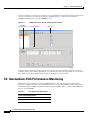
5.1 Threshold Performance Monitoring
5-1
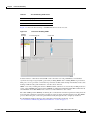
5.2 Intermediate-Path Performance Monitoring
5.3 Pointer Justification Count
5-2
5-4
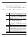
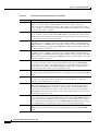
5.4 Performance-Monitoring Parameter Definitions
5-5
Cisco ONS 15600 Troubleshooting Guide, R6.0
March 2009
xvii
Contents
5.5 Optical Card Performance Monitoring 5-9
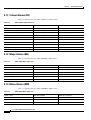
5.5.1 OC-48/STM16 and OC-192/STM64 Card Performance Monitoring Parameters
5.5.2 Physical Layer Parameters 5-11
5-9
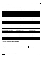
5.6 ASAP Card Performance Monitoring 5-11
5.6.1 ASAP Card Optical Performance Monitoring Parameters 5-11
5.6.2 ASAP Card Ethernet Performance Monitoring Parameters 5-12
5.6.2.1 ASAP Card Ether Port Statistics Window 5-12
5.6.2.2 ASAP Card Ether Ports Utilization Window 5-15
5.6.2.3 ASAP Card Ether Ports History Window 5-16
5.6.2.4 ASAP Card POS Ports Statistics Parameters 5-16
5.6.2.5 ASAP Card POS Ports Utilization Window 5-17
5.6.2.6 ASAP Card Ether Ports History Window 5-17
CHAPTER
6
SNMP
6-1
6.1 SNMP Overview
6-1
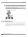
6.2 Basic SNMP Components
6-2
6.3 SNMP External Interface Requirement
6.4 SNMP Version Support
6-4
6.5 SNMP Message Types
6-4
6-4
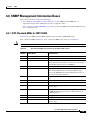
6.6 SNMP Management Information Bases 6-5
6.6.1 IETF-Standard MIBs for ONS 15600 6-5
6.6.2 Proprietary ONS 15600 MIBs 6-6
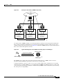
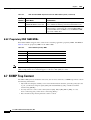
6.7 SNMP Trap Content 6-6
6.7.1 Generic and IETF Traps
6.7.2 Variable Trap Bindings
6-7
6-7
6.8 Proxy Over Firewalls 6-11
6.8.1 Remote Monitoring 6-12
6.8.2 64-Bit RMON Monitoring over DCC 6-12
6.8.2.1 Row Creation in MediaIndependentTable 6-12
6.8.2.2 Row Creation in cMediaIndependentHistoryControlTable
6.8.3 HC-RMON-MIB Support 6-12
6.8.4 Ethernet Statistics RMON Group 6-13
6.8.4.1 Row Creation in etherStatsTable 6-13
6.8.4.2 Get Requests and GetNext Requests 6-13
6.8.4.3 Row Deletion in etherStatsTable 6-13
6.8.5 History Control RMON Group 6-13
6.8.5.1 History Control Table 6-13
6.8.5.2 Row Creation in historyControlTable 6-14
6.8.5.3 Get Requests and GetNext Requests 6-14
6-12
Cisco ONS 15600 Troubleshooting Guide, R6.0
xviii
March 2009
Contents
6.8.5.4 Row Deletion in historyControl Table 6-14
6.8.5.5 Ethernet History RMON Group 6-14
6.8.5.6 64-Bit etherHistoryHighCapacityTable 6-14
6.8.5.7 Alarm RMON Group 6-14
6.8.5.8 Alarm Table 6-15
6.8.5.9 Get Requests and GetNext Requests 6-15
6.8.5.10 Row Deletion in alarmTable 6-15
6.8.5.11 Event RMON Group 6-15
6.8.5.12 Event Table 6-15
6.8.5.13 Log Table 6-15
Cisco ONS 15600 Troubleshooting Guide, R6.0
March 2009
xix
Contents
Cisco ONS 15600 Troubleshooting Guide, R6.0
xx
March 2009
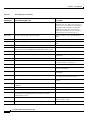
F I G U R E S
Figure 1-1
Facility/Payload Loopback Process on an OC-N Port
Figure 1-2
Terminal Loopback Path on an OC-N Card
Figure 1-3
Terminal Loopback on an OC-N Card with Bridged Signal
Figure 1-4
Cross-Connect Loopback Path on an OC-N Port
Figure 1-5
Network Element with SONET Cross-Connect Loopback Function
Figure 1-6
Facility (Line) Loopback on a Circuit Source OC-N Port
Figure 1-7
Terminal (Inward) Loopback on a Source-Node OC-N Port
Figure 1-8
XC Loopback on a Source OC-N Port
Figure 1-9
Facility (Line) Loopback Path to an Intermediate-Node OC-N Port
Figure 1-10
Facility (Line) Loopback Path to a Destination-Node OC-N Port
Figure 1-11
Facility (Line) Loopback on a Circuit Source Ethernet Port
Figure 1-12
Facility (Line) Loopback on an Intermediate-Node Ethernet Port
Figure 1-13
Terminal Loopback on an Intermediate-Node Ethernet Port
Figure 1-14
Facility (Line) Loopback on a Destination-Node Ethernet Port
Figure 1-15
Terminal Loopback on a Destination-Node Ethernet Port
Figure 1-16
The Delete the CTC Cache Window
Figure 1-17
RJ-45 Pin Numbers
Figure 1-18
Straight-Through Cable Layout
Figure 1-19
Crossover Cable Layout
Figure 4-1
Error Dialog Box
Figure 5-1
SONET Thresholds Tab for Setting Threshold Values
Figure 5-2
STS Tab for Enabling IPPM
Figure 5-3
Viewing Pointer Justification Count Parameters
Figure 5-4
PM Read Points on the OC-48/STM16 and OC-192/STM64 Cards
Figure 6-1
Basic Network Managed by SNMP
Figure 6-2
Example of the Primary SNMP Components
Figure 6-3
Agent Gathering Data from a MIB and Sending Traps to the Manager
1-2
1-4
1-4
1-5
1-5
1-7
1-9
1-13
1-16
1-19
1-26
1-31
1-34
1-38
1-41
1-56
1-68
1-68
1-69
4-1
5-2
5-3
5-4
5-10
6-2
6-3
6-3
Cisco ONS 15600 Troubleshooting Guide, R6.0
March 2009
xxi
Figures
Cisco ONS 15600 Troubleshooting Guide, R6.0
xxii
March 2009
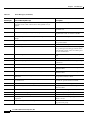
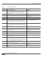
T A B L E S
Table 1
Cisco ONS 15600 Troubleshooting Guide Chapters
Table 1-1
Node is Functioning Improperly or Has Incorrect Data
Table 1-2
Unable to Ping Your PC
Table 1-3
Browser Login Does Not Launch Java
Table 1-4
Unable to Verify the NIC Connection on Your PC
Table 1-5
TCP/IP Connection is Lost
Table 1-6
Cisco Transport Controller Installation Wizard Hangs
Table 1-7
Browser Stalls When Downloading JAR Files From TSC Card
Table 1-8
Cisco Transport Controller Does Not Launch
Table 1-9
Sluggish Cisco Transport Controller Operation or Login Problems
Table 1-10
Node Icon is Gray on Cisco Transport Controller Network View
Table 1-11
Cisco Transport Controller Does Not Recognize the Node
Table 1-12
Username or Password Mismatch
Table 1-13
No IP Connectivity Exists Between Nodes
1-59
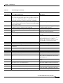
Table 1-14
No IP Connectivity Exists Between Nodes
1-61
Table 1-15
DCC Connection Lost
Table 1-16
Loss of IP Communication in Segmented OSPF Area
Table 1-17
ONS 15600 Switches Timing Reference
Table 1-18
Holdover Synchronization Alarm
Table 1-19
Free-Running Synchronization Mode
1-63
Table 1-20
Daisy-Chained BITS Not Functioning
1-64
Table 1-21
Circuits Remain in PARTIAL Status
1-64
Table 1-22
Bit Errors Appear for a Traffic Card
1-65
Table 1-23
Faulty Fiber-Optic Connections
1-66
Table 1-24
Straight-Through Cable Pinout
1-68
Table 1-25
Crossover Cable Pinout
Table 1-26
Optical Transmit and Receive Levels
Table 1-27
Power Supply Problems
Table 2-1
ONS 15600 Critical Alarm List
Table 2-2
ONS 15600 Major Alarm List
2-2
Table 2-3
ONS 15600 Minor Alarm List
2-2
1-26
1-46
1-49
1-50
1-51
1-52
1-53
1-53
1-54
1-55
1-57
1-58
1-59
1-61
1-62
1-62
1-63
1-69
1-69
1-71
2-2
Cisco ONS 15600 Troubleshooting Guide, R6.0
March 2009
xxiii
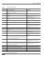
Tables
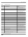
Table 2-4
ONS 15600 NA Conditions List
2-3
Table 2-5
ONS 15600 NR Conditions List
2-4
Table 2-6
ONS 15600 Alarm and Condition Alphabetical List
Table 2-7
Alarm Logical Object Type Definitions
Table 2-8
ONS 15600 Alarm List by Logical Object in Alarm Profile
Table 2-9
Path Alarm Hierarchy
Table 2-10
Facility Alarm Hierarchy
Table 2-11
Near-End Alarm Hierarchy
Table 2-12
Far-End Alarm Hierarchy
Table 2-13
TSC Card-Level Indicators
Table 2-14
TSC Card Network-Level Indicators
Table 2-15
SSXC Card-Level Indicators
2-124
Table 2-16
OC-N Card-Level Indicators
2-125
Table 3-1
ONS 15600 Transient Condition Alphabetical Index
Table 4-1
Error Messages
Table 5-1
Line Terminating Traffic Cards
Table 5-2
Performance Monitoring Parameters
Table 5-3
OC48/STM16 and OC-192/STM64 Card PMs
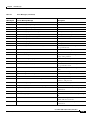
Table 5-4
Non-Normalized Transceiver Physical Optics for the OC-48/STM16 and OC-192/STM64 Cards
Table 5-5
ASAP Card PMs
Table 5-6
ASAP Ethernet Statistics Parameters
Table 5-7
maxBaseRate for STS Circuits
Table 5-8
Ethernet History Statistics per Time Interval
Table 5-9
ASAP Card POS Ports Parameters
Table 6-1
ONS 15600 SNMP Message Types
Table 6-2
IETF Standard MIBs Implemented in the ONS 15600 System
Table 6-3
ONS 15600 Proprietary MIBs
Table 6-4
ONS 15600 Generic Traps
Table 6-5
15600 SNMPv2 Trap Variable Bindings
Table 6-6
RMON History Control Periods and History Categories
2-5
2-7
2-8
2-12
2-12
2-13
2-14
2-124
2-124
3-1
4-1
5-2
5-5
5-10
5-11
5-11
5-12
5-16
5-16
5-16
6-4
6-5
6-6
6-7
6-7
6-14
Cisco ONS 15600 Troubleshooting Guide, R6.0
xxiv
March 2009
About this Guide
This section explains the objectives, intended audience, and organization of this guide and describes the
conventions that convey instructions and other information.
Note
The terms "Unidirectional Path Switched Ring" and "UPSR" may appear in Cisco literature. These terms
do not refer to using Cisco ONS 15xxx products in a unidirectional path switched ring configuration.
Rather, these terms, as well as "Path Protected Mesh Network" and "PPMN," refer generally to Cisco's
path protection feature, which may be used in any topological network configuration. Cisco does not
recommend using its path protection feature in any particular topological network configuration.
Revision History
Date
Notes
March 2007
Revision History Table added for the first time
April 2007
Updated About this Guide chapter
March 2009
Updated input and output voltage information in Power Supply
Problems section of Chapter 1, General Troubleshooting.
This section provides the following information:
•
Document Objectives
•
Audience
•
Document Organization
•
Related Documentation
•
Document Conventions
•
Obtaining Optical Networking Information
•
Obtaining Documentation and Submitting a Service Request
Cisco ONS 15600 Troubleshooting Guide, R6.0
March 2009
xxv
About this Guide
Document Objectives
Document Objectives
The Cisco ONS 15600 Troubleshooting Guide provides troubleshooting procedures for SONET alarms
and error messages, and provides symptoms and solutions for general troubleshooting problems such as
CTC and hardware errors. This guide also contains hardware replacement procedures.
Usethe guide in conjunction with the appropriate publications listed in the Related Documentation
section.
Audience
To use this guide you should be familiar with Cisco or equivalent optical transmission equipment.
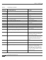
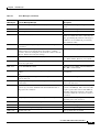
Document Organization
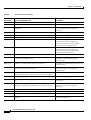
Table 1
Cisco ONS 15600 Troubleshooting Guide Chapters
Title
Summary
Chapter 1, “General Troubleshooting”
Provides procedures for troubleshooting the most
common problems encountered when operating a
Cisco ONS 15600.
Chapter 2, “Alarm Troubleshooting”
Provides ONS 15600 alarm and condition
severities, descriptions, and when necessary,
troubleshooting procedures.
Chapter 3, “Transients Conditions.”
Describes transient (temporary) conditions on the
ONS 15600.
Chapter 4, “Error Messages”
Defines error messages for the ONS 15600.
Chapter 5, “Performance Monitoring”
Provides definitions of all performance monitoring
parameters for ONS 15600 cards and ports.
Chapter 6, “SNMP”
Describes Simple Network Management Protocol
(SNMP) as implemented by the ONS 15600.
Related Documentation
Use this Cisco ONS 15600 Troubleshooting Guide in conjunction with the following referenced
publications:
•
Cisco ONS 15600 Reference Manual
Provides detailed card specifications, hardware and software feature descriptions, network topology
information, and network element defaults.
•
Cisco ONS 15600 Procedure Guide
Provides installation, turn up, test, and maintenance procedures.
•
Cisco ONS SONET TL1 Command Guide
Provides a full TL1 command and autonomous message set including parameters, AIDs, conditions
and modifiers for the Cisco ONS 15454, ONS 15327, ONS 15600 and ONS 15310-CL systems.
Cisco ONS 15600 Troubleshooting Guide, R6.0
xxvi
March 2009
About this Guide
Document Conventions
•
Cisco ONS SONET TL1 Reference Guide
Provides general information, procedures, and errors for TL1 in the ONS 15454, ONS 15327,
ONS 15600, and ONS 15310-CL systems.
•
Release Notes for the Cisco ONS 15600 Release 6.0
Provides caveats, closed issues, and new feature and functionality information.
Document Conventions
This publication uses the following conventions:
Convention
Application
boldface
Commands and keywords in body text.
italic
Command input that is supplied by the user.
[
Keywords or arguments that appear within square brackets are optional.
]
{x|x|x}
A choice of keywords (represented by x) appears in braces separated by
vertical bars. The user must select one.
Ctrl
The control key. For example, where Ctrl + D is written, hold down the
Control key while pressing the D key.
screen font
Examples of information displayed on the screen.
boldface screen font
Examples of information that the user must enter.
<
Command parameters that must be replaced by module-specific codes.
>
Note
Means reader take note. Notes contain helpful suggestions or references to material not covered in the
document.
Caution
Means reader be careful. In this situation, the user might do something that could result in equipment
damage or loss of data.
Cisco ONS 15600 Troubleshooting Guide, R6.0
March 2009
xxvii
About this Guide
Document Conventions
Warning
IMPORTANT SAFETY INSTRUCTIONS
This warning symbol means danger. You are in a situation that could cause bodily injury. Before you
work on any equipment, be aware of the hazards involved with electrical circuitry and be familiar
with standard practices for preventing accidents. Use the statement number provided at the end of
each warning to locate its translation in the translated safety warnings that accompanied this
device. Statement 1071
SAVE THESE INSTRUCTIONS
Waarschuwing
BELANGRIJKE VEILIGHEIDSINSTRUCTIES
Dit waarschuwingssymbool betekent gevaar. U verkeert in een situatie die lichamelijk letsel kan
veroorzaken. Voordat u aan enige apparatuur gaat werken, dient u zich bewust te zijn van de bij
elektrische schakelingen betrokken risico's en dient u op de hoogte te zijn van de standaard
praktijken om ongelukken te voorkomen. Gebruik het nummer van de verklaring onderaan de
waarschuwing als u een vertaling van de waarschuwing die bij het apparaat wordt geleverd, wilt
raadplegen.
BEWAAR DEZE INSTRUCTIES
Varoitus
TÄRKEITÄ TURVALLISUUSOHJEITA
Tämä varoitusmerkki merkitsee vaaraa. Tilanne voi aiheuttaa ruumiillisia vammoja. Ennen kuin
käsittelet laitteistoa, huomioi sähköpiirien käsittelemiseen liittyvät riskit ja tutustu
onnettomuuksien yleisiin ehkäisytapoihin. Turvallisuusvaroitusten käännökset löytyvät laitteen
mukana toimitettujen käännettyjen turvallisuusvaroitusten joukosta varoitusten lopussa näkyvien
lausuntonumeroiden avulla.
SÄILYTÄ NÄMÄ OHJEET
Attention
IMPORTANTES INFORMATIONS DE SÉCURITÉ
Ce symbole d'avertissement indique un danger. Vous vous trouvez dans une situation pouvant
entraîner des blessures ou des dommages corporels. Avant de travailler sur un équipement, soyez
conscient des dangers liés aux circuits électriques et familiarisez-vous avec les procédures
couramment utilisées pour éviter les accidents. Pour prendre connaissance des traductions des
avertissements figurant dans les consignes de sécurité traduites qui accompagnent cet appareil,
référez-vous au numéro de l'instruction situé à la fin de chaque avertissement.
CONSERVEZ CES INFORMATIONS
Warnung
WICHTIGE SICHERHEITSHINWEISE
Dieses Warnsymbol bedeutet Gefahr. Sie befinden sich in einer Situation, die zu Verletzungen führen
kann. Machen Sie sich vor der Arbeit mit Geräten mit den Gefahren elektrischer Schaltungen und
den üblichen Verfahren zur Vorbeugung vor Unfällen vertraut. Suchen Sie mit der am Ende jeder
Warnung angegebenen Anweisungsnummer nach der jeweiligen Übersetzung in den übersetzten
Sicherheitshinweisen, die zusammen mit diesem Gerät ausgeliefert wurden.
BEWAHREN SIE DIESE HINWEISE GUT AUF.
Cisco ONS 15600 Troubleshooting Guide, R6.0
xxviii
March 2009
About this Guide
Document Conventions
Avvertenza
IMPORTANTI ISTRUZIONI SULLA SICUREZZA
Questo simbolo di avvertenza indica un pericolo. La situazione potrebbe causare infortuni alle
persone. Prima di intervenire su qualsiasi apparecchiatura, occorre essere al corrente dei pericoli
relativi ai circuiti elettrici e conoscere le procedure standard per la prevenzione di incidenti.
Utilizzare il numero di istruzione presente alla fine di ciascuna avvertenza per individuare le
traduzioni delle avvertenze riportate in questo documento.
CONSERVARE QUESTE ISTRUZIONI
Advarsel
VIKTIGE SIKKERHETSINSTRUKSJONER
Dette advarselssymbolet betyr fare. Du er i en situasjon som kan føre til skade på person. Før du
begynner å arbeide med noe av utstyret, må du være oppmerksom på farene forbundet med
elektriske kretser, og kjenne til standardprosedyrer for å forhindre ulykker. Bruk nummeret i slutten
av hver advarsel for å finne oversettelsen i de oversatte sikkerhetsadvarslene som fulgte med denne
enheten.
TA VARE PÅ DISSE INSTRUKSJONENE
Aviso
INSTRUÇÕES IMPORTANTES DE SEGURANÇA
Este símbolo de aviso significa perigo. Você está em uma situação que poderá ser causadora de
lesões corporais. Antes de iniciar a utilização de qualquer equipamento, tenha conhecimento dos
perigos envolvidos no manuseio de circuitos elétricos e familiarize-se com as práticas habituais de
prevenção de acidentes. Utilize o número da instrução fornecido ao final de cada aviso para
localizar sua tradução nos avisos de segurança traduzidos que acompanham este dispositivo.
GUARDE ESTAS INSTRUÇÕES
¡Advertencia!
INSTRUCCIONES IMPORTANTES DE SEGURIDAD
Este símbolo de aviso indica peligro. Existe riesgo para su integridad física. Antes de manipular
cualquier equipo, considere los riesgos de la corriente eléctrica y familiarícese con los
procedimientos estándar de prevención de accidentes. Al final de cada advertencia encontrará el
número que le ayudará a encontrar el texto traducido en el apartado de traducciones que acompaña
a este dispositivo.
GUARDE ESTAS INSTRUCCIONES
Varning!
VIKTIGA SÄKERHETSANVISNINGAR
Denna varningssignal signalerar fara. Du befinner dig i en situation som kan leda till personskada.
Innan du utför arbete på någon utrustning måste du vara medveten om farorna med elkretsar och
känna till vanliga förfaranden för att förebygga olyckor. Använd det nummer som finns i slutet av
varje varning för att hitta dess översättning i de översatta säkerhetsvarningar som medföljer denna
anordning.
SPARA DESSA ANVISNINGAR
Cisco ONS 15600 Troubleshooting Guide, R6.0
March 2009
xxix
About this Guide
Document Conventions
Cisco ONS 15600 Troubleshooting Guide, R6.0
xxx
March 2009
About this Guide
Document Conventions
Aviso
INSTRUÇÕES IMPORTANTES DE SEGURANÇA
Este símbolo de aviso significa perigo. Você se encontra em uma situação em que há risco de lesões
corporais. Antes de trabalhar com qualquer equipamento, esteja ciente dos riscos que envolvem os
circuitos elétricos e familiarize-se com as práticas padrão de prevenção de acidentes. Use o
número da declaração fornecido ao final de cada aviso para localizar sua tradução nos avisos de
segurança traduzidos que acompanham o dispositivo.
GUARDE ESTAS INSTRUÇÕES
Advarsel
VIGTIGE SIKKERHEDSANVISNINGER
Dette advarselssymbol betyder fare. Du befinder dig i en situation med risiko for
legemesbeskadigelse. Før du begynder arbejde på udstyr, skal du være opmærksom på de
involverede risici, der er ved elektriske kredsløb, og du skal sætte dig ind i standardprocedurer til
undgåelse af ulykker. Brug erklæringsnummeret efter hver advarsel for at finde oversættelsen i de
oversatte advarsler, der fulgte med denne enhed.
GEM DISSE ANVISNINGER
Cisco ONS 15600 Troubleshooting Guide, R6.0
March 2009
xxxi
About this Guide
Document Conventions
Cisco ONS 15600 Troubleshooting Guide, R6.0
xxxii
March 2009
About this Guide
Document Conventions
Obtaining Optical Networking Information
This section contains information that is specific to optical networking products. For information that
pertains to all of Cisco, refer to the “Obtaining Documentation and Submitting a Service Request”
section on page 33.
Where to Find Safety and Warning Information
For safety and warning information, refer to the Cisco Optical Transport Products Safety and
Compliance Information document that accompanied the product. This publication describes the
international agency compliance and safety information for the Cisco ONS 15600 systems. It also
includes translations of the safety warnings that appear in the ONS 15600 SDH system documentation.
Cisco Optical Networking Product Documentation CD-ROM
Optical networking-related documentation, including Cisco ONS 15xxx product documentation, is
available in a CD-ROM package that ships with your product. The Optical Networking Product
Documentation CD-ROM is updated periodically and may be more current than printed documentation.
Obtaining Documentation and Submitting a Service Request
For information on obtaining documentation, submitting a service request, and gathering additional
information, see the monthly What’s New in Cisco Product Documentation, which also lists all new and
revised Cisco technical documentation, at:
http://www.cisco.com/en/US/docs/general/whatsnew/whatsnew.html
Subscribe to the What’s New in Cisco Product Documentation as a Really Simple Syndication (RSS)
feed and set content to be delivered directly to your desktop using a reader application. The RSS feeds
are a free service and Cisco currently supports RSS version 2.0.
Cisco ONS 15600 Troubleshooting Guide, R6.0
March 2009
xxxiii
About this Guide
Document Conventions
Cisco ONS 15600 Troubleshooting Guide, R6.0
xxxiv
March 2009
C H A P T E R
1
General Troubleshooting
This chapter provides procedures for troubleshooting the most common problems encountered when
operating a Cisco ONS 15600. To troubleshoot specific ONS 15600 alarms, see Chapter 2, “Alarm
Troubleshooting.” If you cannot find what you are looking for, contact the Cisco Technical Assistance
Center (1 800 553-2447).
This chapter begins with the following sections on network problems:
•
1.1 Network Troubleshooting Tests, page 1-2—Describes loopbacks and hairpin circuits, which
you can use to test circuit paths through the network or logically isolate faults.
Note
For network acceptance tests, refer to the Cisco ONS 15600 Procedure Guide.
•
1.2 Troubleshooting Optical Circuit Paths With Loopbacks, page 1-6—Explains how to perform the
tests described in the “1.1 Network Troubleshooting Tests” section on page 1-2 for OC-N ports and
cards.
•
1.3 Troubleshooting an Ethernet Circuit Path With Loopbacks, page 1-25—Explains how to
perform the tests described in the “1.1 Network Troubleshooting Tests” section on page 1-2 for
Gigabit Ethernet (GIGE) ASAP card ports.
The remaining sections describe symptoms, problems, and solutions that are categorized according to
the following topics:
•
1.4 Using CTC Diagnostics, page 1-44—Provides procedures for testing LED operation and
downloading a machine-readable diagnostic information file to be used by Technical Support.
•
1.5 Restoring the Database to a Previous or Original Configuration, page 1-46—Provides
troubleshooting for node operation errors that might require procedures to restore software data or
restoring the node to the default setup.
•
1.6 PC Connectivity Troubleshooting, page 1-46—Provides troubleshooting procedures for PC and
network connectivity to the ONS 15600.
•
1.7 CTC Operation Troubleshooting, page 1-52—Provides troubleshooting procedures for CTC
log-in or operation problems.
•
1.8 Circuits and Timing, page 1-62—Provides troubleshooting procedures for circuit creation, error
reporting, and timing reference errors and alarms.
•
1.9 Fiber and Cabling, page 1-65—Provides troubleshooting procedures for fiber and cabling
connectivity errors.
•
1.10 Power Supply Problems, page 1-70—Provides troubleshooting information for common
power supply issues.
Cisco ONS 15600 Troubleshooting Guide, R6.0
March 2009
1-1
Chapter 1
General Troubleshooting
1.1 Network Troubleshooting Tests
1.1 Network Troubleshooting Tests
Use loopbacks to test newly created circuits before running live traffic or to logically locate the source
of a network failure. All ONS 15600 optical (OC-N) cards allow loopbacks.
Caution
On optical cards, a loopback can only be applied to a port that is out of service.
1.1.1 Facility Loopbacks
The following sections give general information about facility loopback operations and specific
information about ONS 15600 card loopback activity.
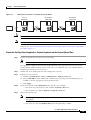
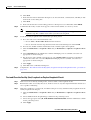
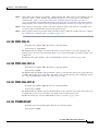
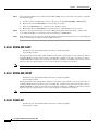
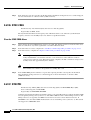
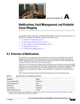
1.1.1.1 General Behavior
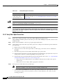
A facility loopback tests the line interface unit (LIU) of an ASAP card or OC-48 card and related cabling.
After applying a facility loopback on a port, use a test set to run traffic over the loopback. A successful
facility loopback isolates the LIU or the cabling plant as the potential cause of a network problem. To
test an OC-N port or Ethernet port, connect an optical test set to the port and perform a facility loopback.
Alternately, use a loopback or hairpin circuit on a card that is farther along the circuit path.
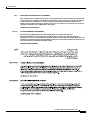
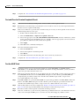
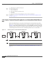
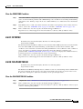
Figure 1-1 shows a facility/payload loopback on an OC-N port.
Figure 1-1
Facility/Payload Loopback Process on an OC-N Port
Test Set
OC-Nx
SSXC
OC-Ny
124003
x1
Caution
Before performing a facility loopback on an OC-N port, be sure the ASAP card contains at least two data
communications channel (DCC) paths to the node where the card is installed. A second DCC provides
a nonlooped path to log into the node after the loopback is applied, enabling you to remove the facility
loopback. Ensuring a second DCC is not necessary if you are directly connected to the ONS 15600
containing the loopbacked ASAP card.
1.1.1.2 Card Behavior
Loopbacks either terminate or bridge the loopback signal. When a port terminates a facility loopback
signal, the signal only loops back to the originating port and is not transmitted downstream. When a port
bridges a loopback signal, the signal loops back to the originating port and is also transmitted
downstream.
The loopback itself is listed in the Conditions window. For example, the window would list the
LPBKFACILITY condition for a tested port. (The Alarms window will show AS-MT, which means that
alarms are suppressed on the facility during loopback.)
Cisco ONS 15600 Troubleshooting Guide, R6.0
1-2
March 2009
Chapter 1
General Troubleshooting
1.1.2 Payload Loopbacks
In addition to the Conditions window listing, the following behaviors occur:
Caution
•
If an electrical or optical port is in the Out-of-Service and Management, Disabled
(OOS-MA,DSBLD) service state, it injects an AIS signal upstream and downstream.
•
When an electrical or optical port is placed in the OOS-MA,MT service state before loopback
testing, the port clears the AIS signal upstream and downstream unless there is a service-affecting
defect that would also cause an AIS signal to be injected. For more information about placing ports
into alternate states for testing, refer to the “Change Card Settings” chapter of the Cisco ONS 15600
Procedure Guide.
A lock out of protection must be executed before putting a two-fiber or four-fiber BLSR span into a
facility loopback state. That is, a span lockout of one side (such as the east side) of a two-fiber BLSR is
required before operating a facility loopback on the same (east) side of the ring. A span lockout of one
protection side (such as the east protection side) of a four-fiber BLSR is required before operating a
facility loopback on the same (east) side working line of the ring. If you do not execute the lockout prior
to creating the loopback, the ring can become stuck in an anomalous state after you release the loopback.
1.1.2 Payload Loopbacks
The payload loopback is similar to a facility loopback but occurs on OC-192 cards. Another difference
is that a payload loopback terminates and regenerates section and line overhead; a facility loopback
passes section and line overhead through, untouched. The OC-48 card executes a facility loopback by
looping the signal back just before the framer chip. The OC-192 card cannot do this because of the
differences in the design. To execute a loopback on an OC-192 card, the loopback signal passes through
the framer chip and then terminates and regenerates line and section overhead. Since OC-192 card line
and section overhead is terminated and regenerated, this type of loopback is called a payload loopback.
1.1.3 Terminal Loopbacks
The following sections give general information about ASAP card and OC-48 card terminal loopback
operations.
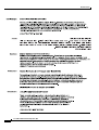
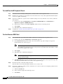
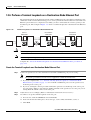
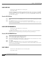
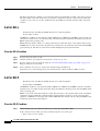
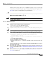
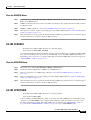
1.1.3.1 General Behavior
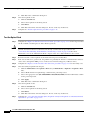
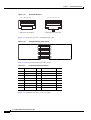
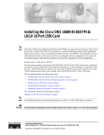
A terminal loopback tests a circuit path as it passes through the SSXC card and loops back from the card
with the loopback. Figure 1-2 shows a terminal loopback on an OC-48 card. The test-set traffic enters
the optical or Ethernet port and travels through the cross-connect card to the optical port. A terminal
loopback turns the signal around before it reaches the LIU and sends it back through the SSXC card to
the card. This test verifies that the SSXC card and terminal circuit paths are valid, but does not test the
LIU on the optical card.
Cisco ONS 15600 Troubleshooting Guide, R6.0
March 2009
1-3
Chapter 1
General Troubleshooting
1.1.3 Terminal Loopbacks
Figure 1-2
Terminal Loopback Path on an OC-N Card
DS-N
XC
OC-N
137598
Test Set
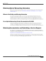
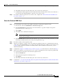
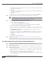
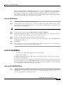
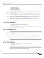
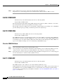
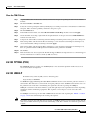
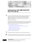
1.1.3.2 Card Behavior
ONS 15600 terminal port loopbacks can either terminate or bridge the signal. (Some ONS 15600 cards
bridge the loopback signal, while others terminate it.)
If a port terminates a terminal loopback signal, the signal only loops back to the originating port and is
not transmitted downstream. If the port bridges a loopback signal, the signal loops back to the originating
port and is also transmitted downstream.
An OC-N terminal loopback example is shown in Figure 1-3.
Figure 1-3
Terminal Loopback on an OC-N Card with Bridged Signal
Source
ONS Node
OC-N
XC
Destination
ONS Node
OC-N
Test Set
OC-N
XC
OC-N
137605
Test Set
The loopback is listed in the Conditions window. For example, the window would list the
LPBKTERMINAL condition or LPBKFACILITY condition for a tested port. (The Alarms window
would show AS-MT, which indicates that all alarms are suppressed on the port during loopback testing.)
In addition to the Conditions window listing, the following behaviors occur:
Caution
•
If an electrical or optical port is in the OOS-MA,DSBLD service state, it injects an AIS signal
upstream and downstream.
•
When an optical or Ethernet port is placed in the OOS-MA,MT service state before loopback testing,
the port clears the AIS signal upstream and downstream unless there is a service-affecting defect
that would also cause an AIS signal to be injected. For more information about placing ports into
alternate states for testing, refer to the “Change Card Settings” chapter of the Cisco ONS 15600
Procedure Guide.
A lock out of protection must be executed before putting a two-fiber or four-fiber BLSR span into a
terminal loopback state. That is, a span lockout of one side (such as the east side) of a two-fiber BLSR
is required before operating a facility loopback on the same (east) side of the ring. A span lockout of one
Cisco ONS 15600 Troubleshooting Guide, R6.0
1-4
March 2009
Chapter 1
General Troubleshooting
1.1.4 Cross-Connect (XC) Loopbacks
protection side (such as the east protection side) of a four-fiber BLSR is required before operating a
terminal loopback on the same (east) side working line of the ring. If you do not execute the lockout prior
to creating the loopback, the ring can become stuck in an anomalous state after you release the loopback.
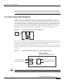
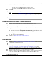
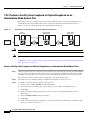
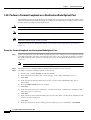
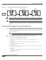
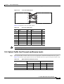
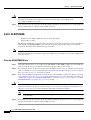
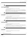
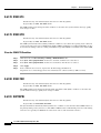
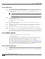
1.1.4 Cross-Connect (XC) Loopbacks
An XC loopback tests a SONET STS circuit path as it passes through a single-shelf cross-connect
(SSXC) card and loops back to the port being tested without affecting other traffic on the optical port.
Cross-connect loopbacks are less invasive than terminal or facility loopbacks. Testing with facility or
terminal loopbacks testing often involve taking down the whole line; however, an XC loopback allows
you to create a loopback on any embedded channel at supported payloads of STS-1 granularity and
higher. For example, you can place a loopback on a single STS-1, STS-3c, STS-6c, etc. on an optical
facility without interrupting the other STS circuits. Figure 1-4 shows the XC loopback path.
Figure 1-4
OC-Nx
SSXC
OC-Ny
x
124001
Test Set
Cross-Connect Loopback Path on an OC-N Port
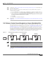
This test can be conducted locally or remotely through the CTC interface without on-site personnel. It
takes place on an OC-48, OC-192, or ASAP port and tests the traffic path on that STS (or higher) circuit
through the port and SSXC. The signal path is similar to a facility loopback.
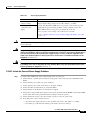
The XC loopback breaks down the existing path and creates a new cross-connect—a hairpin—while the
source of the original path is set to inject a line-side AIS-P. The signal path and AIS injection are shown
in Figure 1-5.
Figure 1-5
Network Element with SONET Cross-Connect Loopback Function
Equipment to perform
framing, scrambling, etc.
(such as signal terminating equipment)
AIS
O/E
External signals from
and to other equipment
R
Internal signals to and from
other equipment in the NE
OOS
T
124542
E/O
Note
If a terminal or facility loopback exists on a port, you cannot create an XC loopback on it.
Cisco ONS 15600 Troubleshooting Guide, R6.0
March 2009
1-5
Chapter 1
General Troubleshooting
1.2 Troubleshooting Optical Circuit Paths With Loopbacks
Note
When testing OC-192 signals with jitter analyzers, be sure to verify with the manufacturer that you are
using the most current test equipment. Some test equipment has demonstrated false high jitter readings
caused by accumulated jitter dependencies within the test equipment.
1.2 Troubleshooting Optical Circuit Paths With Loopbacks
Facility loopbacks or payload loopbacks, terminal loopbacks, and cross-connect (XC) loopback circuits
are often used together to test the circuit path through the network or to logically isolate a fault.
Performing a loopback test at each point along the circuit path systematically isolates possible points of
failure.
The procedures in this section apply to OC-48, OC-192, and ASAP optical ports. (For instructions on
ASAP Ethernet ports, go to the “1.3 Troubleshooting an Ethernet Circuit Path With Loopbacks” section
on page 1-25.) The example in this section tests an OC-N circuit on a three-node BLSR. Using a series
of facility, cross-connect, and terminal loopbacks, the example scenario traces the circuit path, tests the
possible failure points, and eliminates them. The logical progression contains seven network test
procedures:
Note
Note
The test sequence for your circuits will differ according to the type of circuit and network topology.
1.
A facility (or payload) loopback on the source-node OC-N port
2.
A terminal loopback on the source-node OC-N port
3.
A cross-connect loopback on the source OC-N port
4.
A facility (or payload) loopback on the intermediate-node OC-N port
5.
A terminal loopback on the intermediate-node OC-N port
6.
A facility (or payload) loopback on the destination-node OC-N port
7.
A terminal loopback on the destination-node OC-N port
Facility and terminal loopback tests require on-site personnel.
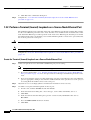
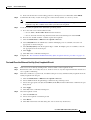
1.2.1 Perform a Facility (Line) Loopback or Payload Loopback on a
Source-Node Optical Port
The OC-48 card or ASAP card optical port facility loopback test is performed on the node source port
in the network circuit. Likewise for the OC-192 payload loopback. In the testing situation used in this
example, the source optical port in the source node. Completing a successful facility loopback on this
port isolates the optical port as a possible failure point. Figure 1-6 shows an example of a facility
loopback on a circuit source OC-N port.
Cisco ONS 15600 Troubleshooting Guide, R6.0
1-6
March 2009
Chapter 1
General Troubleshooting
1.2.1 Perform a Facility (Line) Loopback or Payload Loopback on a Source-Node Optical Port
Figure 1-6
Facility (Line) Loopback on a Circuit Source OC-N Port
Source
ONS Node
OC-N
XC
Intermediate
ONS Node
OC-N
OC-N
XC
Destination
ONS Node
OC-N
OC-N
XC
OC-N
138601
Test Set
Caution
Note
Performing a loopback on an in-service circuit is service-affecting.
Facility and payload loopbacks require on-site personnel.
Complete the “Create the Facility (Line) Loopback or Payload Loopback on the Source Optical Port”
procedure on page 1-7.
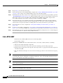
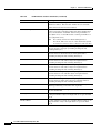
Create the Facility (Line) Loopback or Payload Loopback on the Source Optical Port
Step 1
Connect an optical test set to the port you are testing.
For specific procedures to use the test set equipment, consult the manufacturer.
Note
Use appropriate cabling to attach the Tx and Rx terminals of the optical test set to the port you are
testing. The Tx and Rx terminals connect to the same port. Adjust the test set accordingly. (Refer to
manufacturer instructions for test-set use.)
Step 2
In CTC node view, double-click the card to display the card view.
Step 3
Take the port out of service:
Step 4
Step 5
a.
Clicking the Maintenance > Line (or Maintenance > Optical > Line) tabs.
b.
Choose OOS,MT from the Admin State column for the port being tested. If multiple ports are
available, select the appropriate row for the desired port.
c.
Click Apply.
Create the loopback. On the Maintenance tab, click the correct subtab:
•
For an OC-48 card or OC-192 card, click the Loopback > Port tabs.
•
For an ASAP card, click the Optical > Loopback > Port tabs.
Choose the loopback type:
If multiple ports are available, choose the row associated with the correct port and then configure
the loopback.
Note
•
For an OC-48 card, click Facility (Line) in the Loopback Type column.
Cisco ONS 15600 Troubleshooting Guide, R6.0
March 2009
1-7
Chapter 1
General Troubleshooting
1.2.1 Perform a Facility (Line) Loopback or Payload Loopback on a Source-Node Optical Port
•
For an OC-192 card, click Payload in the Loopback Type column.
•
For an ASAP card, click Facility (Line) in the Loopback Type column.
Step 6
Click Apply.
Step 7
Click Yes in the confirmation dialog box.
It is normal for the “LPBKFACILITY (OCN)” condition on page 2-88 or the
“LPBKTERMINAL (GIGE)” condition on page 2-89 to appear during loopback setup. The
condition clears when you remove the loopback.
Note
Step 8
Complete the “Test and Clear the Facility (Line) Loopback or Payload Loopback Circuit” procedure on
page 1-8.
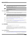
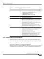
Test and Clear the Facility (Line) Loopback or Payload Loopback Circuit
Step 1
If the test set is not already sending traffic, send test traffic on the loopback circuit.
Step 2
Examine the traffic received by the test set. Look for errors or any other signal information that the test
set is capable of indicating.
Step 3
If the test set indicates a good circuit, no further testing is necessary with the facility loopback. Clear the
loopback:
Step 4
a.
Click the Maintenance > Loopback > Port (or Maintenance > Optical > Loopback > Port) tabs.
b.
Choose the appropriate state (IS; OOS,DSBLD; OOS,MT; IS,AINS) from the Admin State column
for the port being tested. If multiple ports are available, select the appropriate row for the desired
port. (The new admin state will override the loopback.)
c.
Click Apply.
d.
Click Yes in the confirmation dialog box.
Complete the “Test the Optical Card” procedure on page 1-8.
Test the Optical Card
Step 1
Complete the “Replace an OC-48 Card or OC-192 Card” procedure on page 2-138 for the suspected bad
card and replace it with a known-good one.
Caution
Removing a card that currently carries traffic on one or more ports can cause a traffic hit. To avoid this,
perform an external switch if a switch has not already occurred. See the procedures in the
“2.8.2 Protection Switching, Lock Initiation, and Clearing” section on page 2-126. For more
information, refer to the “Maintain the Node” chapter of the Cisco ONS 15600 Procedure Guide.
Step 2
Resend test traffic on the loopback circuit with a known-good card installed.
Step 3
If the test set indicates a good circuit, the problem was probably the defective card. Return the defective
card to Cisco through the RMA process. Contact Cisco Technical Support (1 800 553-2447).
Cisco ONS 15600 Troubleshooting Guide, R6.0
1-8
March 2009
Chapter 1
General Troubleshooting
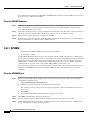
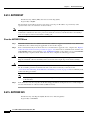
1.2.2 Perform a Terminal (Inward) Loopback on a Source-Node Optical Port
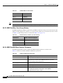
Step 4
Complete the “Replace an OC-48 Card or OC-192 Card” procedure on page 2-138 for the faulty card.
Step 5
Clear the facility loopback:
Step 6
If the test set indicates a good circuit, no further testing is necessary with the facility or payload
loopback. Clear the loopback:
Step 7
a.
Click the Maintenance > Loopback > Port (or Maintenance > Optical > Loopback > Port) tabs.
b.
Choose the appropriate state (IS; OOS,DSBLD; OOS,MT; IS,AINS) from the Admin State column
for the port being tested. If multiple ports are available, select the appropriate row for the desired
port. (The new admin state will override the loopback.)
c.
Click Apply.
d.
Click Yes in the confirmation dialog box.
Complete the “1.2.2 Perform a Terminal (Inward) Loopback on a Source-Node Optical Port” procedure
on page 1-9.
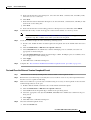
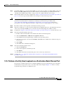
1.2.2 Perform a Terminal (Inward) Loopback on a Source-Node Optical Port
The terminal loopback test is only available on ASAP card optical and Ethernet ports. (This section will
only address the optical ports; Ethernet ports are covered in 1.3 Troubleshooting an Ethernet Circuit
Path With Loopbacks, page 1-25.) Terminal loopbacks are not available on OC-48 or OC-192 cards.
To create a terminal loopback, create a bidirectional circuit originating on the node source optical port
and looping back on the node source optical port. You then proceed with the terminal loopback test.
Completing a successful terminal loopback to a node source port verifies that the circuit is good to the
source port. Figure 1-7 shows an example of a terminal loopback on a source optical port.
Figure 1-7
Terminal (Inward) Loopback on a Source-Node OC-N Port
Source
ONS Node
OC-N
XC
Intermediate
ONS Node
OC-N
OC-N
XC
Destination
ONS Node
OC-N
OC-N
XC
OC-N
137602
Test Set
Caution
Note
Performing a loopback on an in-service circuit is service-affecting.
Terminal loopbacks require on-site personnel.
Complete the “Create the Terminal (Inward) Loopback on a Source-Node Optical Port” procedure on
page 1-10.
Cisco ONS 15600 Troubleshooting Guide, R6.0
March 2009
1-9
Chapter 1
General Troubleshooting
1.2.2 Perform a Terminal (Inward) Loopback on a Source-Node Optical Port
Create the Terminal (Inward) Loopback on a Source-Node Optical Port
Step 1
Connect an optical test set to the ASAP card optical port you are testing:
Note
Step 2
Step 3
a.
If you just completed the “1.2.1 Perform a Facility (Line) Loopback or Payload Loopback on a
Source-Node Optical Port” procedure on page 1-6 for an ASAP card optical port, leave the optical
test set hooked up.
b.
If you are starting the current procedure without the optical test set hooked up to the source optical
port, use appropriate cabling to attach the Tx and Rx terminals of the optical test set to the port you
are testing. Both Tx and Rx connect to the same port.
c.
Adjust the test set accordingly. (Refer to manufacturer instructions for test-set use.)
Use CTC to set up the terminal loopback on the test port:
a.
In node view, click the Circuits tab and click Create.
b.
In the Circuit Creation dialog box, choose the type, such as STS, and number, such as 1.
c.
Click Next.
d.
In the next Circuit Creation dialog box, give the circuit an easily identifiable name such as
Opt1toOpt2.
e.
Leave the Bidirectional check box checked.
f.
Click Next.
g.
In the Circuit Creation source dialog box, select the same Node, card Slot, Port, and STS (or VT)
where the test set is connected.
h.
Click Next.
i.
In the Circuit Creation destination dialog box, use the same Node, card Slot, Port, and STS (or VT)
used for the source dialog box.
j.
Click Next.
k.
In the Circuit Creation circuit routing preferences dialog box, leave all defaults. Click Finish.
Confirm that the newly created circuit appears on the Circuits tab list as a two-way circuit.
Note
Step 4
For specific procedures to use the test set equipment, consult the manufacturer.
It is normal for the “LPBKTERMINAL (OCN)” condition on page 2-89 to appear during a
loopback setup. The condition clears when you remove the loopback.
Create the terminal loopback on the destination port being tested:
a.
In node view, double-click the ASAP card.
b.
Click the Maintenance > Optical > Loopback > Port tabs.
c.
Select OOS,MT from the Admin State column. If there are multiple available circuits, select the row
appropriate for the desired port.
d.
Select Terminal (Inward) from the Loopback Type column.
e.
Click Apply.
f.
Click Yes in the confirmation dialog box.
Cisco ONS 15600 Troubleshooting Guide, R6.0
1-10
March 2009
Chapter 1
General Troubleshooting
1.2.2 Perform a Terminal (Inward) Loopback on a Source-Node Optical Port
Step 5
Complete the “Test and Clear the Terminal Loopback Circuit” procedure on page 1-11.
Test and Clear the Terminal Loopback Circuit
Step 1
If the test set is not already sending traffic, send test traffic on the loopback circuit.
Step 2
Examine the test traffic being received by the test set. Look for errors or any other signal information
that the test set is capable of indicating.
Step 3
If the test set indicates a good circuit, no further testing is necessary on the loopback circuit. Clear the
terminal loopback state on the port:
Step 4
Step 5
a.
Double-click the ASAP in the source node.
a.
Click the Maintenance > Optical > Loopback > Port tabs.
b.
Choose the appropriate state (IS; OOS,DSBLD; OOS,MT; IS,AINS) from the Admin State column
for the port being tested. If multiple ports are available, select the appropriate row for the desired
port. (The new admin state will override the loopback.)
c.
Click Apply.
d.
Click Yes in the confirmation dialog box.
Clear the terminal loopback circuit:
a.
Click the Circuits tab.
b.
Choose the loopback circuit being tested.
c.
Click Delete.
d.
Click Yes in the Delete Circuits dialog box. Do not check any check boxes.
Complete the “Test the ASAP Card” procedure on page 1-11.
Test the ASAP Card
Step 1
Determine whether you are experiencing trouble on a single SFP (PPM), on all PPMs within a
4PIO (PIM), or on all 4PIO used in that ASAP card. If there is only partial failure, you may be able to
replace this part rather than the entire card.
Step 2
If the errors are being observed on one port but not all ports of the ASAP, you may only need to replace
that SFP (PPM). Remove the errored SFP (PPM) and replace it with a known-good SFP (PPM) by
completing the procedures for this in the “Install Cards and Fiber-Optic Cable” chapter of the
Cisco ONS 15600 Procedure Guide.
Step 3
If all SFPs (PPMs) on a particular 4PIO (PIM) are experiencing problems, the 4PIO (PIM) is indicated.
Remove this 4PIO (PIM) and replace it with a known-good one using the procedures for this in the
“Install Cards and Fiber-Optic Cable” chapter of the Cisco ONS 15600 Procedure Guide.
Step 4
If the trouble still is not located, complete the “Replace an OC-48 Card or OC-192 Card” procedure on
page 2-138 for the suspected bad ASAP card and replace it with a known-good one.
Step 5
Resend test traffic on the loopback circuit with a known-good card.
Step 6
If the test set indicates a good circuit, the problem was probably the defective card. Return the defective
card to Cisco through the RMA process. Contact Cisco Technical Support (1 800 553-2447).
Cisco ONS 15600 Troubleshooting Guide, R6.0
March 2009
1-11
Chapter 1
General Troubleshooting
1.2.3 Perform an XC Loopback on the Source Optical Port
Step 7
Complete the “Replace an OC-48 Card or OC-192 Card” procedure on page 2-138 for the defective card.
Step 8
Clear the terminal loopback on the port before testing the next segment of the network circuit path:
Step 9
Step 10
a.
Double-click the ASAP card in the source node with the terminal loopback.
a.
Click the Maintenance > Optical > Loopback > Port tabs.
b.
Choose the appropriate state (IS; OOS,DSBLD; OOS,MT; IS,AINS) from the Admin State column
for the port being tested. If multiple ports are available, select the appropriate row for the desired
port. (The new admin state will override the loopback.)
c.
Click Apply.
d.
Click Yes in the confirmation dialog box.
Clear the terminal loopback circuit before testing the next segment of the network circuit path:
a.
Click the Circuits tab.
b.
Choose the loopback circuit being tested.
c.
Click Delete.
d.
Click Yes in the Delete Circuits dialog box. Do not check any check boxes.
Complete the “1.2.3 Perform an XC Loopback on the Source Optical Port” procedure on page 1-12.
1.2.3 Perform an XC Loopback on the Source Optical Port
Note
This procedure is performed from an OC-N card or ASAP card optical port to test the cross-connect
circuit connection.
Note
You can perform an XC loopback on either the circuit source working or the protect port of a 1+1
protection group.
Note
XC loopbacks do not require on-site personnel.
The XC loopback test is available for OC-48, OC-192, and ASAP cards and occurs on an optical circuit
transiting the SSXC card in a network circuit. Completing a successful XC loopback from an optical port
through the SSXC card eliminates the SSXC card as the source of trouble for a faulty circuit. Figure 1-8
shows an example of an XC loopback path on a source OC-N port.
Cisco ONS 15600 Troubleshooting Guide, R6.0
1-12
March 2009
Chapter 1
General Troubleshooting
1.2.3 Perform an XC Loopback on the Source Optical Port
Figure 1-8
XC Loopback on a Source OC-N Port
Test Set
OC-Nx
OC-Ny
137603
XC
Complete the “Create the XC Loopback on the Source-Node Optical Port” procedure on page 1-13.
Create the XC Loopback on the Source-Node Optical Port
Step 1
Connect an optical test set to the optical port you are testing:
Note
For specific procedures to use the test set equipment, consult the manufacturer.
a.
If you just completed the “1.2.2 Perform a Terminal (Inward) Loopback on a Source-Node Optical
Port” procedure on page 1-9, leave the optical test set hooked up to the source-node port.
b.
If you are starting the current procedure without the optical test set hooked up to the source port,
use appropriate cabling to attach the Tx and Rx terminals of the optical test set to the port you are
testing. The Tx and Rx terminals connect to the same port.
Step 2
Adjust the test set accordingly. (Refer to manufacturer instructions for test-set use.)
Step 3
Use CTC to put the circuit being tested out of service:
Step 4
Step 5
a.
In node view, click the Circuits tab.
b.
Click the circuit and then click Edit.
c.
In the Edit Circuit dialog box, click the State tab.
d.
Choose OOS,MT from the Target Circuit Admin State drop-down list.
e.
Click Apply.
f.
Click Yes in the confirmation dialog box.
Use CTC to set up the XC loopback on the circuit being tested:
a.
In node view, double-click the OC-N card to display the card view.
b.
Click the Maintenance > Loopback > SONET STS tabs (or Maintenance > Optical >
Loopback > SONET STS tabs).
c.
Click the check box in the XC Loopback column for the port being tested.
d.
Click Apply.
e.
Click Yes in the confirmation dialog box.
Complete the “Test and Clear the XC Loopback Circuit” procedure on page 1-14.
Cisco ONS 15600 Troubleshooting Guide, R6.0
March 2009
1-13
Chapter 1
General Troubleshooting
1.2.3 Perform an XC Loopback on the Source Optical Port
Test and Clear the XC Loopback Circuit
Step 1
If the test set is not already sending traffic, send test traffic on the loopback circuit.
Step 2
Examine the test traffic received by the test set. Look for errors or any other signal information that the
test set is capable of indicating.
Step 3
If the test set indicates a good circuit, no further testing is necessary with the cross-connect. Clear the
XC loopback:
Step 4
a.
In card view, click the Maintenance > Loopback > SONET STS tabs (or Maintenance >
Optical > Loopback > SONET STS tabs).
b.
Uncheck the check box in the XC Loopback column for the circuit being tested.
c.
Click Apply.
d.
Click Yes in the confirmation dialog box.
Complete the “Test the Alternate SSXC Card” procedure on page 1-14.
Test the Alternate SSXC Card
Step 1
Do a manual data copy switch of the SSXC cards before retesting the XC loopback circuit:
a.
In node view, select the Maintenance > Preferred Copy tabs.
b.
In the Set Preferred drop-down menu, select the alternate copy. (For example, if Copy B is
preferred and in use, select Copy A.)
Note
c.
Click Apply.
d.
Click Yes in the confirmation dialog box.
Note
e.
Step 2
Note CTC Copy A refers to the SSXC card in Slot 6. Copy B refers to the SSXC card in
Slot 8. Either copy might be chosen as the preferred copy SSXC. The other SSXC is called
the alternate SSXC in this chapter.
If you attempt a preferred copy switch and the switch is unsuccessful, a problem is present
with the alternate SSXC.
Click Refresh until the tab shows that the alternate copy you selected is now the preferred copy. The
Currently Used field will show the newly-selected preferred copy.
Resend test traffic on the XC loopback circuit.
The test traffic now travels through the alternate cross-connect card.
Step 3
If the test set indicates a faulty circuit, assume the cross-connect card is not causing the problem. Clear
the XC loopback circuit:
a.
Click the Circuits tab.
b.
Choose the XC loopback circuit being tested.
c.
Click Delete.
Cisco ONS 15600 Troubleshooting Guide, R6.0
1-14
March 2009
Chapter 1
General Troubleshooting
1.2.3 Perform an XC Loopback on the Source Optical Port
Step 4
d.
Click Yes in the Delete Circuits dialog box. Do not check any check boxes.
e.
Confirm that the XC loopback circuit is deleted from the Circuits tab list. If the test set indicates a
good circuit, the problem might be a defective cross-connect card.
To confirm a defective preferred cross-connect card, complete the “Retest the Preferred SSXC Card”
procedure on page 1-15.
Retest the Preferred SSXC Card
Step 1
Do a manual data copy switch of the SSXC cards before retesting the loopback circuit:
a.
In node view, select the Maintenance > Preferred Copy tabs.
b.
In the Set Preferred drop-down menu, select the alternate copy. (For example, if Copy B is
preferred and in use, select Copy A.)
c.
Click Apply.
d.
Click Yes on the confirmation dialog box.
Note
e.
If you attempt a preferred copy switch and the switch is unsuccessful, a problem is present
with the alternate SSXC.
Click Refresh until the tab shows that the alternate copy you selected is now the preferred copy. The
Currently Used field will show the newly-selected preferred copy.
Step 2
Resend test traffic on the loopback circuit.
Step 3
If the test set indicates a faulty circuit, the problem is probably the defective card. Return the defective
card to Cisco through the RMA process. Contact Cisco Technical Support (1 800 553-2447) and proceed
to Step 4. If the circuit is not shown to be faulty and the card is not shown to be defective, you are
finished with testing.
Step 4
Complete the “Replace an SSXC Card” procedure on page 2-137 for the defective card. Perform Step 5.
Step 5
If the test set indicates a good circuit, the cross-connect card might have had a temporary problem that
was cleared by the side switch. Clear the XC loopback circuit:
Step 6
a.
Click the Circuits tab.
b.
Choose the XC loopback circuit being tested.
c.
Click Delete.
d.
Click Yes in the Delete Circuits dialog box. Do not check any check boxes.
Complete the “1.2.4 Perform a Facility (Line) Loopback or Payload Loopback on an Intermediate-Node
Optical Port” procedure on page 1-16.
Cisco ONS 15600 Troubleshooting Guide, R6.0
March 2009
1-15
Chapter 1
General Troubleshooting
1.2.4 Perform a Facility (Line) Loopback or Payload Loopback on an Intermediate-Node Optical Port
1.2.4 Perform a Facility (Line) Loopback or Payload Loopback on an
Intermediate-Node Optical Port
Performing an OC-48 or ASAP card optical facility loopback (or OC-192 payload loopback) on an
intermediate port isolates whether this node is causing circuit failure. In the situation shown in
Figure 1-9, the test is being performed on an intermediate OC-N port.
Figure 1-9
Facility (Line) Loopback Path to an Intermediate-Node OC-N Port
Source
ONS Node
OC-N
XC
Intermediate
ONS Node
OC-N
OC-N
XC
Destination
ONS Node
OC-N
OC-N
XC
OC-N
138600
Test Set
Caution
Note
Performing a loopback on an in-service circuit is service-affecting.
Facility and payload loopbacks require on-site personnel.
Complete the “Create a Facility (Line) Loopback or Payload Loopback on an Intermediate-Node Optical
Port” procedure on page 1-16.
Create a Facility (Line) Loopback or Payload Loopback on an Intermediate-Node Optical Port
Step 1
Connect an optical test set to the port you are testing. If you are starting the current procedure without
the optical test set hooked up to the source port port, use appropriate cabling to attach the Tx and Rx
terminals of the optical test set to the port you are testing. Both Tx and Rx connect to the same port.
For specific procedures to use the test set equipment, consult the manufacturer.
Step 2
Adjust the test set accordingly. (Refer to manufacturer instructions for test-set use.)
Step 3
Use CTC to set up the facility loopback on the test port:
a.
In node view, click the Circuits tab and click Create.
b.
In the Circuit Creation dialog box, choose the type, such as STS, and number, such as 1.
c.
Click Next.
d.
In the next Circuit Creation dialog box, give the circuit an easily identifiable name such as
Opt1toOpt3.
e.
Leave the Bidirectional check box checked.
f.
Click Next.
g.
In the Circuit Creation source dialog box, select the same Node, card Slot, Port, and STS (or VT)
where the test set is connected.
Cisco ONS 15600 Troubleshooting Guide, R6.0
1-16
March 2009
Chapter 1
General Troubleshooting
1.2.4 Perform a Facility (Line) Loopback or Payload Loopback on an Intermediate-Node Optical Port
Step 4
h.
Click Next.
i.
In the Circuit Creation destination dialog box, use the same Node, card Slot, Port, and STS (or VT)
used for the source dialog box.
j.
Click Next.
k.
In the Circuit Creation circuit routing preferences dialog box, leave all defaults. Click Finish.
Confirm that the newly created circuit appears on the Circuits tab list as a two-way circuit.
It is normal for the “LPBKFACILITY (OCN)” condition on page 2-88 to appear during a
loopback setup. The condition clears when you remove the loopback.
Note
Step 5
Create the facility loopback on the intermediate port being tested:
a.
Step 6
Go to the node view of the intermediate node:
•
Choose View > Go To Other Node from the menu bar.
•
Choose the node from the drop-down list in the Select Node dialog box and click OK.
b.
In node view, double-click the intermediate-node card that requires the loopback.
c.
Click the Maintenance > Loopback > Port tabs (or Maintenance > Optical > Loopback > Port
tabs).
d.
Select OOS,MT from the Admin State column. If multiple ports are available, select the row
appropriate for the desired port.
e.
For an OC-48 card or ASAP card optical port, select Facility (Line) from the Loopback Type
column. For an OC-192 card, select Payload. If multiple ports are available, select the row
appropriate for the desired port.
f.
Click Apply.
g.
Click Yes in the confirmation dialog box.
Complete the “Test and Clear the Facility (Line) Loopback or Payload Loopback Circuit” procedure on
page 1-17.
Test and Clear the Facility (Line) Loopback or Payload Loopback Circuit
Step 1
If the test set is not already sending traffic, send test traffic on the loopback circuit.
Step 2
Examine the traffic received by the test set. Look for errors or any other signal information that the test
set is capable of indicating.
Step 3
If the test set indicates a good circuit, no further testing is necessary with the facility loopback. Clear the
facility loopback from the port:
a.
Click the Maintenance > Loopback > Port tabs (or Maintenance > Optical > Loopback > Port
tabs).
b.
Choose None from the Loopback Type column for the port being tested.
c.
Choose the appropriate state (IS; OOS,DSBLD; OOS,MT; IS,AINS) from the Admin State column
for the port being tested.
d.
Click Apply.
Cisco ONS 15600 Troubleshooting Guide, R6.0
March 2009
1-17
Chapter 1
General Troubleshooting
1.2.4 Perform a Facility (Line) Loopback or Payload Loopback on an Intermediate-Node Optical Port
e.
Step 4
Step 5
Click Yes in the confirmation dialog box.
Clear the loopback circuit:
a.
Click the Circuits tab.
b.
Choose the loopback circuit being tested.
c.
Click Delete.
d.
Click Yes in the Delete Circuits dialog box. Do not check any check boxes.
Complete the “Test the Optical Card” procedure on page 1-18.
Test the Optical Card
Step 1
Complete the “Replace an OC-48 Card or OC-192 Card” procedure on page 2-138 for the suspected bad
OC-N or ASAP card and replace it with a known-good one.
Caution
Removing a card that currently carries traffic on one or more ports can cause a traffic hit. To avoid this,
perform an external switch if a switch has not already occurred. See the procedures in the
“2.8.2 Protection Switching, Lock Initiation, and Clearing” section on page 2-126. For more
information, refer to the “Maintain the Node” chapter of the Cisco ONS 15600 Procedure Guide.
Step 2
Resend test traffic on the loopback circuit with a known-good card installed.
Step 3
If the test set indicates a good circuit, the problem was probably the defective card. Return the defective
card to Cisco through the RMA process. Contact Cisco Technical Support (1 800 553-2447).
Step 4
Complete the “Replace an OC-48 Card or OC-192 Card” procedure on page 2-138 for the faulty card.
Step 5
Clear the facility loopback from the port:
Step 6
Step 7
a.
Click the Maintenance > Loopback > Port tabs (or Maintenance > Optical > Loopback > Port
tabs).
b.
Choose None from the Loopback Type column for the port being tested.
c.
Choose the appropriate state (IS; OOS,DSBLD; OOS,MT; IS,AINS) from the Admin State column
for the port being tested.
d.
Click Apply.
e.
Click Yes in the confirmation dialog box.
Clear the loopback circuit:
a.
Click the Circuits tab.
b.
Choose the loopback circuit being tested.
c.
Click Delete.
d.
Click Yes in the Delete Circuits dialog box. Do not check any check boxes.
Complete the “1.2.5 Perform a Facility (Line) Loopback or Payload Loopback on a Destination-Node
Optical Port” procedure on page 1-19.
Cisco ONS 15600 Troubleshooting Guide, R6.0
1-18
March 2009
Chapter 1
General Troubleshooting
1.2.5 Perform a Facility (Line) Loopback or Payload Loopback on a Destination-Node Optical Port
1.2.5 Perform a Facility (Line) Loopback or Payload Loopback on a
Destination-Node Optical Port
You perform a facility loopback test at the destination port to determine whether this local port is the
source of circuit trouble. The example in Figure 1-10 shows a facility loopback being performed on a
destination-node OC-N port.
Figure 1-10
Facility (Line) Loopback Path to a Destination-Node OC-N Port
Source
ONS Node
OC-N
XC
Intermediate
ONS Node
OC-N
OC-N
XC
Destination
ONS Node
OC-N
OC-N
XC
OC-N
137599
Test Set
Caution
Note
Performing a loopback on an in-service circuit is service-affecting.
Facility loopbacks require on-site personnel.
Complete the “Create the Facility (Line) Loopback or Payload Loopback on a Destination-Node Optical
Port” procedure on page 1-19.
Create the Facility (Line) Loopback or Payload Loopback on a Destination-Node Optical Port
Step 1
Connect an optical test set to the OC-N or ASAP optical port you are testing. If you are starting the
current procedure without the optical test set hooked up to the source port, use appropriate cabling to
attach the Tx and Rx terminals of the optical test set to the port you are testing. Both Tx and Rx connect
to the same port.
Note
For specific procedures to use the test set equipment, consult the manufacturer.
Step 2
Adjust the test set accordingly. (Refer to manufacturer instructions for test-set use.)
Step 3
Use CTC to set up the facility circuit on the test port:
a.
In node view, click the Circuits tab and click Create.
b.
In the Circuit Creation dialog box, choose the type, such as STS, and number, such as 1.
c.
Click Next.
d.
In the next Circuit Creation dialog box, give the circuit an easily identifiable name such as
Opt1toOpt5.
e.
Leave the Bidirectional check box checked.
f.
Click Next.
Cisco ONS 15600 Troubleshooting Guide, R6.0
March 2009
1-19
Chapter 1
General Troubleshooting
1.2.5 Perform a Facility (Line) Loopback or Payload Loopback on a Destination-Node Optical Port
Step 4
g.
In the Circuit Creation source dialog box, select the same Node, card Slot, Port, and STS (or VT)
where the test set is connected.
h.
Click Next.
i.
In the Circuit Creation destination dialog box, use the same Node, card Slot, Port, and STS (or VT)
used for the source dialog box.
j.
Click Next.
k.
In the Circuit Creation circuit routing preferences dialog box, leave all defaults. Click Finish.
Confirm that the newly created circuit appears on the Circuits tab list as a two-way circuit.
It is normal for the “LPBKFACILITY (OCN)” condition on page 2-88 to appear during a
loopback setup. The condition clears when you remove the loopback.
Note
Step 5
Create the facility loopback on the destination port being tested:
a.
Step 6
Go to the node view of the destination node:
•
Choose View > Go To Other Node from the menu bar.
•
Choose the node from the drop-down list in the Select Node dialog box and click OK.
b.
In node view, double-click the card that requires the loopback.
c.
Click the Maintenance > Loopback > Port tabs (or Maintenance > Optical > Loopback > Port
tabs).
d.
Select OOS,MT from the Admin State column. If multiple ports are available, select the row
appropriate for the desired port.
e.
For an ASAP card or OC-48 card, select Facility (Line) from the Loopback Type column. For an
OC-192 card, select Payload. If multiple ports are available, select the row appropriate for the
desired port.
f.
Click Apply.
g.
Click Yes in the confirmation dialog box.
Complete the “Test and Clear the Optical Facility (Line) Loopback or Payload Loopback Circuit”
procedure on page 1-20.
Test and Clear the Optical Facility (Line) Loopback or Payload Loopback Circuit
Step 1
If the test set is not already sending traffic, send test traffic on the loopback circuit.
Step 2
Examine the traffic received by the test set. Look for errors or any other signal information that the test
set is capable of indicating.
Step 3
If the test set indicates a good circuit, no further testing is necessary with the facility loopback. Clear the
facility loopback from the port:
a.
Click the Maintenance > Loopback > Port tabs (or Maintenance > Optical > Loopback > Port
tabs).
b.
Choose None from the Loopback Type column for the port being tested.
c.
Choose the appropriate state (IS; OOS,DSBLD; OOS,MT; IS,AINS) from the Admin State column
for the port being tested.
Cisco ONS 15600 Troubleshooting Guide, R6.0
1-20
March 2009
Chapter 1
General Troubleshooting
1.2.5 Perform a Facility (Line) Loopback or Payload Loopback on a Destination-Node Optical Port
Step 4
Step 5
d.
Click Apply.
e.
Click Yes in the confirmation dialog box.
Clear the loopback circuit:
a.
Click the Circuits tab.
b.
Choose the loopback circuit being tested.
c.
Click Delete.
d.
Click Yes in the Delete Circuits dialog box. Do not check any check boxes.
Complete the “Test the Optical Card” procedure on page 1-21.
Test the Optical Card
Step 1
Complete the “Replace an OC-48 Card or OC-192 Card” procedure on page 2-138 for the suspected bad
OC-N or ASAP card and replace it with a known-good one.
Caution
Removing a card that currently carries traffic on one or more ports can cause a traffic hit. To avoid this,
perform an external switch if a switch has not already occurred. See the procedures in the
“2.8.2 Protection Switching, Lock Initiation, and Clearing” section on page 2-126. For more
information, refer to the “Maintain the Node” chapter of the Cisco ONS 15600 Procedure Guide.
Step 2
Resend test traffic on the loopback circuit with a known-good card installed.
Step 3
If the test set indicates a good circuit, the problem was probably the defective card. Return the defective
card to Cisco through the RMA process. Contact Cisco Technical Support (1 800 553-2447).
Step 4
Complete the “Replace an OC-48 Card or OC-192 Card” procedure on page 2-138 for the faulty card.
Step 5
Clear the loopback on the port:
Step 6
Step 7
a.
Click the Maintenance > Loopback > Port tabs (or Maintenance > Optical > Loopback > Port
tabs).
b.
Choose None from the Loopback Type column for the port being tested.
c.
Choose the appropriate state (IS; OOS,DSBLD; OOS,MT; IS,AINS) from the Admin State column
for the port being tested.
d.
Click Apply.
e.
Click Yes in the confirmation dialog box.
Clear the loopback circuit:
a.
Click the Circuits tab.
b.
Choose the loopback circuit being tested.
c.
Click Delete.
d.
Click Yes in the Delete Circuits dialog box. Do not check any check boxes.
Complete the “1.2.6 Perform a Terminal Loopback on a Destination-Node Optical Port” procedure on
page 1-22.
Cisco ONS 15600 Troubleshooting Guide, R6.0
March 2009
1-21
Chapter 1
General Troubleshooting
1.2.6 Perform a Terminal Loopback on a Destination-Node Optical Port
1.2.6 Perform a Terminal Loopback on a Destination-Node Optical Port
The terminal loopback at the destination-node ASAP card optical port is the final local hardware error
elimination in the circuit troubleshooting process. If this test is completed successfully, you have verified
that the circuit is good up to the destination port.
Caution
Performing a loopback on an in-service circuit is service-affecting.
Note
OC-48 and OC-192 cards are not capable of terminal loopbacks.
Note
Terminal loopbacks require on-site personnel.
Complete the “Create the Terminal Loopback on a Destination-Node Optical Port” procedure on
page 1-22.
Create the Terminal Loopback on a Destination-Node Optical Port
Step 1
Connect an optical test set to the ASAP card optical port you are testing: If you are starting the current
procedure without the optical test set hooked up to the source port, use appropriate cabling to attach the
Tx and Rx terminals of the optical test set to the port you are testing. Both Tx and Rx connect to the
same port.
Note
For specific procedures to use the test set equipment, consult the manufacturer.
Step 2
Adjust the test set accordingly. (Refer to manufacturer instructions for test-set use.)
Step 3
Use CTC to set up the terminal loopback on the test port:
a.
In node view, click the Circuits tab and click Create.
b.
In the Circuit Creation dialog box, choose the type, such as STS, and number, such as 1.
c.
Click Next.
d.
In the next Circuit Creation dialog box, give the circuit an easily identifiable name such as
Opt1toOpt6.
e.
Leave the Bidirectional check box checked.
f.
Click Next.
g.
In the Circuit Creation source dialog box, select the same Node, card Slot, Port, and STS (or VT)
where the test set is connected.
h.
Click Next.
i.
In the Circuit Creation destination dialog box, use the same Node, card Slot, Port, and STS (or VT)
used for the source dialog box.
j.
Click Next.
k.
In the Circuit Creation circuit routing preferences dialog box, leave all defaults. Click Finish.
Cisco ONS 15600 Troubleshooting Guide, R6.0
1-22
March 2009
Chapter 1
General Troubleshooting
1.2.6 Perform a Terminal Loopback on a Destination-Node Optical Port
Step 4
Confirm that the newly created circuit appears on the Circuits tab list as a two-way circuit.
It is normal for the “LPBKTERMINAL (OCN)” condition on page 2-89 to appear during a
loopback setup. The condition clears when you remove the loopback.
Note
Step 5
Create the terminal loopback on the destination port being tested:
a.
Step 6
Go to the node view of the destination node:
•
Choose View > Go To Other Node from the menu bar.
•
Choose the node from the drop-down list in the Select Node dialog box and click OK.
b.
In node view, double-click the card that requires the loopback.
c.
Click the Maintenance > Optical > Loopback > Port tab.
d.
Select OOS,MT from the Admin State column. If multiple ports are available, select the row
appropriate for the desired port.
e.
Select Terminal (Inward) from the Loopback Type column. If multiple ports are available, select
the row appropriate for the desired port.
f.
Click Apply.
g.
Click Yes in the confirmation dialog box.
Complete the “Test and Clear the Optical Terminal Loopback Circuit” procedure on page 1-23.
Test and Clear the Optical Terminal Loopback Circuit
Step 1
If the test set is not already sending traffic, send test traffic on the loopback circuit.
Step 2
Examine the test traffic being received by the test set. Look for errors or any other signal information
that the test set is capable of indicating.
Step 3
If the test set indicates a good circuit, no further testing is necessary on the loopback circuit. Clear the
terminal loopback from the port:
Step 4
a.
Double-click the destination-node ASAP card with the terminal loopback.
b.
Click the Maintenance > Optical > Loopback > Port tab.
c.
Select None from the Loopback Type column for the port being tested.
d.
Select the appropriate state (IS; OOS,DSBLD; OOS,MT; IS,AINS) in the Admin State column for
the port being tested.
e.
Click Apply.
f.
Click Yes in the confirmation dialog box.
Clear the terminal loopback circuit:
a.
Click the Circuits tab.
b.
Choose the loopback circuit being tested.
c.
Click Delete.
d.
Click Yes in the Delete Circuits dialog box. Do not check any check boxes.
Cisco ONS 15600 Troubleshooting Guide, R6.0
March 2009
1-23
Chapter 1
General Troubleshooting
1.2.6 Perform a Terminal Loopback on a Destination-Node Optical Port
The entire circuit path has now passed its comprehensive series of loopback tests. This circuit
qualifies to carry live traffic.
Step 5
If the test set indicates a faulty circuit, the problem might be a faulty card.
Step 6
Complete the “Test the ASAP Card” procedure on page 1-24.
Test the ASAP Card
Step 1
Determine whether you are experiencing trouble on a single SFP (PPM), on all PPMs within a
4PIO (PIM), or on all 4PIO used in that ASAP card. If there is only partial failure, you may be able to
replace this part rather than the entire card.
Step 2
If the errors are being observed on one port but not all ports of the ASAP, you may only need to replace
that SFP (PPM). Remove the errored SFP (PPM) and replace it with a known-good SFP (PPM) by
completing the procedures for this in the “Install Cards and Fiber-Optic Cable” chapter of the
Cisco ONS 15600 Procedure Guide.
Step 3
If all SFPs (PPMs) on a particular 4PIO (PIM) are experiencing problems, the 4PIO (PIM) is indicated.
Remove this 4PIO (PIM) and replace it with a known-good one using the procedures for this in the
“Install Cards and Fiber-Optic Cable” chapter of the Cisco ONS 15600 Procedure Guide.
Step 4
If the trouble still is not located, complete the “Replace an OC-48 Card or OC-192 Card” procedure on
page 2-138 for the suspected bad ASAP card and replace it with a known-good one.
Caution
Removing a card that currently carries traffic on one or more ports can cause a traffic hit. To avoid this,
perform an external switch if a switch has not already occurred. See the procedures in the
“2.8.2 Protection Switching, Lock Initiation, and Clearing” section on page 2-126. For more
information, refer to the “Maintain the Node” chapter of the Cisco ONS 15600 Procedure Guide.
Step 5
Resend test traffic on the loopback circuit with a known-good card.
Step 6
If the test set indicates a good circuit, the problem was probably the defective card. Return the defective
card to Cisco through the RMA process. Contact Cisco Technical Support (1 800 553-2447).
Step 7
Complete the “Replace an OC-48 Card or OC-192 Card” procedure on page 2-138 for the defective card.
Step 8
Clear the terminal loopback on the port:
Step 9
a.
Double-click the source-node card with the terminal loopback.
b.
Click the Maintenance > Optical > Loopback > Port tabs.
c.
Select None from the Loopback Type column for the port being tested.
d.
Select the appropriate state (IS; OOS,DSBLD; OOS,MT; IS,AINS) in the Admin State column for
the port being tested.
e.
Click Apply.
f.
Click Yes in the confirmation dialog box.
Clear the terminal loopback circuit:
a.
Click the Circuits tab.
b.
Choose the loopback circuit being tested.
c.
Click Delete.
Cisco ONS 15600 Troubleshooting Guide, R6.0
1-24
March 2009
Chapter 1
General Troubleshooting
1.3 Troubleshooting an Ethernet Circuit Path With Loopbacks
d.
Click Yes in the Delete Circuits dialog box. Do not check any check boxes.
The entire optical circuit path has now passed its comprehensive series of loopback tests. This circuit
qualifies to carry live traffic.
1.3 Troubleshooting an Ethernet Circuit Path With Loopbacks
Facility (line) loopbacks and terminal loopbacks are often used together to test the circuit path through
the network or to logically isolate a fault. Performing a loopback test at each point along the circuit path
systematically isolates possible points of failure.
You can use these procedures only on the ASAP card Ethernet ports in the ONS 15600 system. The
example in this section tests an Ethernet circuit on a three-node BLSR. Using a series of facility
loopbacks and terminal loopbacks, the example scenario traces the circuit path, tests the possible failure
points, and eliminates them. The logical progression contains six network test procedures:
Note
Note
The test sequence for your circuits will differ according to the type of circuit and network topology.
1.
A facility loopback on the source-node Ethernet port
2.
A terminal loopback on the source-node Ethernet port
3.
A facility loopback on the intermediate-node Ethernet port
4.
A terminal loopback on the intermediate-node Ethernet port
5.
A facility loopback on the destination-node Ethernet port
6.
A terminal loopback on the destination-node Ethernet port
Facility and terminal loopback tests require on-site personnel.
1.3.1 Perform a Facility (Line) Loopback on a Source-Node Ethernet Port
The facility loopback test is performed on the node source port in the network circuit. In the testing
situation used in this example, the source is an ASAP Ethernet port in the source node. Completing a
successful facility loopback on this port isolates the port as a possible failure point. Figure 1-11 shows
an example of a facility loopback on a circuit source Ethernet port.
Note
Facility loopbacks require on-site personnel.
Cisco ONS 15600 Troubleshooting Guide, R6.0
March 2009
1-25
Chapter 1
General Troubleshooting
1.3.1 Perform a Facility (Line) Loopback on a Source-Node Ethernet Port
Figure 1-11
Facility (Line) Loopback on a Circuit Source Ethernet Port
Source
ONS Node
Intermediate
ONS Node
XC
Ethernet
Destination
ONS Node
XC
XC
Ethernet
Ethernet
Ethernet
Ethernet
Ethernet
137610
Test Set
Caution
Performing a loopback on an in-service circuit is service-affecting.
Complete the “Create the Facility (Line) Loopback on the Source-Node Ethernet Port” procedure on
page 1-26.
Create the Facility (Line) Loopback on the Source-Node Ethernet Port
Step 1
Connect an optical test set to the ASAP Ethernet port you are testing.
Note
For specific procedures to use the test set equipment, consult the manufacturer.
Use appropriate cabling to attach the Tx and Rx terminals of the optical test set to the port you are
testing. The Tx and Rx terminals connect to the same port.
Step 2
Adjust the test set accordingly. (Refer to manufacturer instructions for test-set use.)
Step 3
In CTC node view, double-click the card to display the card view.
Step 4
Click the Maintenance > Ethernet > Loopback > Port tabs.
Step 5
Choose OOS,MT from the Admin State column for the port being tested. If multiple ports are available,
select the appropriate row for the desired port.
Step 6
Choose Facility (Line) from the Loopback Type column for the port being tested. If multiple ports are
available, select the appropriate row for the desired port.
Step 7
Click Apply.
Step 8
Click Yes in the confirmation dialog box.
Note
Step 9
It is normal for the “LPBKFACILITY (GIGE)” condition on page 2-87 to appear during
loopback setup. The condition clears when you remove the loopback.
Complete the “Test and Clear the Facility (Line) Loopback Circuit” procedure on page 1-26.
Test and Clear the Facility (Line) Loopback Circuit
Step 1
If the test set is not already sending traffic, send test traffic on the loopback circuit.
Cisco ONS 15600 Troubleshooting Guide, R6.0
1-26
March 2009
Chapter 1
General Troubleshooting
1.3.1 Perform a Facility (Line) Loopback on a Source-Node Ethernet Port
Step 2
Examine the traffic received by the test set. Look for errors or any other signal information that the test
set is capable of indicating.
Step 3
If the test set indicates a good circuit, no further testing is necessary with the facility loopback. Clear the
facility loopback:
Step 4
a.
Click the Maintenance > Ethernet > Loopback > Port tab.
b.
Choose None from the Loopback Type column for the port being tested.
c.
Choose the appropriate state (IS; OOS,DSBLD; OOS,MT) from the Admin State column for the port
being tested.
d.
Click Apply.
e.
Click Yes in the confirmation dialog box.
Complete the “Test the ASAP Card” procedure on page 1-27.
Test the ASAP Card
Step 1
Determine whether you are experiencing trouble on a single SFP (PPM), on all PPMs within a
4PIO (PIM), or on all 4PIO used in that ASAP card. If there is only partial failure, you may be able to
replace this part rather than the entire card.
Step 2
If the errors are being observed on one port but not all ports of the ASAP, you may only need to replace
that SFP (PPM). Remove the errored SFP (PPM) and replace it with a known-good SFP (PPM) by
completing the procedures for this in the “Install Cards and Fiber-Optic Cable” chapter of the
Cisco ONS 15600 Procedure Guide.
Step 3
If all SFPs (PPMs) on a particular 4PIO (PIM) are experiencing problems, the 4PIO (PIM) is indicated.
Remove this 4PIO (PIM) and replace it with a known-good one using the procedures for this in the
“Install Cards and Fiber-Optic Cable” chapter of the Cisco ONS 15600 Procedure Guide.
Step 4
If the trouble still is not located, complete the “Replace an OC-48 Card or OC-192 Card” procedure on
page 2-138 for the suspected bad ASAP card and replace it with a known-good one.
Caution
Removing a card that currently carries traffic on one or more ports can cause a traffic hit. To avoid this,
perform an external switch if a switch has not already occurred. See the procedures in the
“2.8.2 Protection Switching, Lock Initiation, and Clearing” section on page 2-126. For more
information, refer to the “Maintain the Node” chapter of the Cisco ONS 15600 Procedure Guide.
Step 5
Resend test traffic on the loopback circuit with a known-good card installed.
Step 6
If the test set indicates a good circuit, the problem was probably the defective card. Return the defective
card to Cisco through the RMA process. Contact Cisco Technical Support (1 800 553-2447).
Step 7
Complete the “Replace an OC-48 Card or OC-192 Card” procedure on page 2-138 for the faulty card.
Step 8
Clear the facility loopback:
a.
Click the Maintenance > Ethernet > Loopback > Port tab.
b.
Choose None from the Loopback Type column for the port being tested.
c.
Choose the appropriate state (IS; OOS,DSBLD; OOS,MT) from the Admin State column for the port
being tested.
d.
Click Apply.
Cisco ONS 15600 Troubleshooting Guide, R6.0
March 2009
1-27
Chapter 1
General Troubleshooting
1.3.2 Perform a Terminal (Inward) Loopback on a Source-Node Ethernet Port
e.
Step 9
Click Yes in the confirmation dialog box.
Complete the “1.3.2 Perform a Terminal (Inward) Loopback on a Source-Node Ethernet Port”
procedure on page 1-28.
1.3.2 Perform a Terminal (Inward) Loopback on a Source-Node Ethernet Port
The terminal loopback test is performed on the node source Ethernet port. For the circuit in this example,
it is the source Ethernet port in the source node. You first create a bidirectional circuit that starts on the
node destination Ethernet port and loops back on the node source Ethernet port.You then proceed with
the terminal loopback test. Completing a successful terminal loopback to a node source port verifies that
the circuit is good to the source port.
Caution
Note
Performing a loopback on an in-service circuit is service-affecting.
Terminal loopbacks require on-site personnel.
Complete the “Create the Terminal (Inward) Loopback on a Source-Node Ethernet Port” procedure on
page 1-28.
Create the Terminal (Inward) Loopback on a Source-Node Ethernet Port
Step 1
Connect an optical test set to the ASAP card Ethernet port you are testing:
Note
For specific procedures to use the test set equipment, consult the manufacturer.
a.
If you just completed the “1.3.1 Perform a Facility (Line) Loopback on a Source-Node Ethernet
Port” procedure on page 1-25, leave the optical test set hooked up to the Ethernet port in the source
node.
b.
If you are starting the current procedure without the optical test set hooked up to the source Ethernet
port, use appropriate cabling to attach the Tx and Rx terminals of the optical test set to the port you
are testing. Both Tx and Rx connect to the same port.
Step 2
Adjust the test set accordingly. (Refer to manufacturer instructions for test-set use.)
Step 3
Use CTC to set up the terminal loopback on the test port:
a.
In node view, click the Circuits tab and click Create.
b.
In the Circuit Creation dialog box, choose the type, such as STS, and number, such as 1.
c.
Click Next.
d.
In the next Circuit Creation dialog box, give the circuit an easily identifiable name such as
Eth1toEth2.
e.
Leave the Bidirectional check box checked.
f.
Click Next.
Cisco ONS 15600 Troubleshooting Guide, R6.0
1-28
March 2009
Chapter 1
General Troubleshooting
1.3.2 Perform a Terminal (Inward) Loopback on a Source-Node Ethernet Port
Step 4
g.
In the Circuit Creation source dialog box, select the same Node, card Slot, Port, and STS (or VT)
where the test set is connected.
h.
Click Next.
i.
In the Circuit Creation destination dialog box, use the same Node, card Slot, Port, and STS (or VT)
used for the source dialog box.
j.
Click Next.
k.
In the Circuit Creation circuit routing preferences dialog box, leave all defaults. Click Finish.
Confirm that the newly created circuit appears on the Circuits tab list as a two-way circuit.
Note
Step 5
Step 6
It is normal for the “LPBKTERMINAL (GIGE)” condition on page 2-89 to appear during a
loopback setup. The condition clears when you remove the loopback.
Create the terminal loopback on the destination port being tested:
a.
In node view, double-click the card that requires the loopback, such as the ASAP card in the source
node.
b.
Click the Maintenance > Ethernet > Loopback > Port tab.
c.
Select OOS,MT from the Admin State column. If multiple ports are available, select the row
appropriate for the desired port.
d.
Select Terminal (Inward) from the Loopback Type column. If multiple ports are available, select
the row appropriate for the desired port.
e.
Click Apply.
f.
Click Yes in the confirmation dialog box.
Complete the “Test and Clear the Ethernet Terminal Loopback Circuit” procedure on page 1-29.
Test and Clear the Ethernet Terminal Loopback Circuit
Step 1
If the test set is not already sending traffic, send test traffic on the loopback circuit.
Step 2
Examine the test traffic being received by the test set. Look for errors or any other signal information
that the test set is capable of indicating.
Step 3
If the test set indicates a good circuit, no further testing is necessary on the loopback circuit. Clear the
terminal loopback state on the port:
Step 4
a.
Double-click the ASAP card in the source node with the terminal loopback.
b.
Click the Maintenance > Ethernet > Loopback > Port tab.
c.
Select None from the Loopback Type column for the port being tested.
d.
Select the appropriate state (IS; OOS,DSBLD; OOS,MT) in the Admin State column for the port
being tested.
e.
Click Apply.
f.
Click Yes in the confirmation dialog box.
Clear the terminal loopback circuit:
a.
Click the Circuits tab.
Cisco ONS 15600 Troubleshooting Guide, R6.0
March 2009
1-29
Chapter 1
General Troubleshooting
1.3.2 Perform a Terminal (Inward) Loopback on a Source-Node Ethernet Port
Step 5
b.
Choose the loopback circuit being tested.
c.
Click Delete.
d.
Click Yes in the Delete Circuits dialog box. Do not check any check boxes.
Complete the “Test the ASAP Card” procedure on page 1-30.
Test the ASAP Card
Step 1
Determine whether you are experiencing trouble on a single SFP (PPM), on all PPMs within a
4PIO (PIM), or on all 4PIO used in that ASAP card. If there is only partial failure, you may be able to
replace this part rather than the entire card.
Step 2
If the errors are being observed on one port but not all ports of the ASAP, you may only need to replace
that SFP (PPM). Remove the errored SFP (PPM) and replace it with a known-good SFP (PPM) by
completing the procedures for this in the “Install Cards and Fiber-Optic Cable” chapter of the
Cisco ONS 15600 Procedure Guide.
Step 3
If all SFPs (PPMs) on a particular 4PIO (PIM) are experiencing problems, the 4PIO (PIM) is indicated.
Remove this 4PIO (PIM) and replace it with a known-good one using the procedures for this in the
“Install Cards and Fiber-Optic Cable” chapter of the Cisco ONS 15600 Procedure Guide.
Step 4
If the trouble still is not located, complete the “Replace an OC-48 Card or OC-192 Card” procedure on
page 2-138 for the suspected bad ASAP card and replace it with a known-good one.
Caution
Removing a card that currently carries traffic on one or more ports can cause a traffic hit. To avoid this,
perform an external switch if a switch has not already occurred. See the procedures in the
“2.8.2 Protection Switching, Lock Initiation, and Clearing” section on page 2-126. For more
information, refer to the “Maintain the Node” chapter of the Cisco ONS 15600 Procedure Guide.
Step 5
Resend test traffic on the loopback circuit with a known-good card.
Step 6
If the test set indicates a good circuit, the problem was probably the defective card. Return the defective
card to Cisco through the RMA process. Contact Cisco Technical Support (1 800 553-2447).
Step 7
Complete the “Replace an OC-48 Card or OC-192 Card” procedure on page 2-138 for the defective card.
Step 8
Clear the terminal loopback on the port before testing the next segment of the network circuit path:
Step 9
a.
Double-click the card in the source node with the terminal loopback.
b.
Click the Maintenance > Ethernet > Loopback > Port tab.
c.
Select None from the Loopback Type column for the port being tested.
d.
Select the appropriate state (IS; OOS,DSBLD; OOS,MT) in the Admin State column for the port
being tested.
e.
Click Apply.
f.
Click Yes in the confirmation dialog box.
Clear the terminal loopback circuit before testing the next segment of the network circuit path:
a.
Click the Circuits tab.
b.
Choose the loopback circuit being tested.
c.
Click Delete.
Cisco ONS 15600 Troubleshooting Guide, R6.0
1-30
March 2009
Chapter 1
General Troubleshooting
1.3.3 Create a Facility (Line) Loopback on an Intermediate-Node Ethernet Port
d.
Step 10
Click Yes in the Delete Circuits dialog box. Do not check any check boxes.
Complete the “1.3.3 Create a Facility (Line) Loopback on an Intermediate-Node Ethernet Port”
procedure on page 1-31.
1.3.3 Create a Facility (Line) Loopback on an Intermediate-Node Ethernet Port
Performing the facility loopback test on an intermediate port isolates whether this node is causing circuit
failure. It is shown in Figure 1-12.
Figure 1-12
Facility (Line) Loopback on an Intermediate-Node Ethernet Port
Source
ONS Node
Ethernet
XC
Intermediate
ONS Node
Ethernet
Ethernet
XC
Destination
ONS Node
Ethernet
Ethernet
XC
Ethernet
137608
Test Set
Caution
Note
Performing a loopback on an in-service circuit is service-affecting.
Facility loopbacks require on-site personnel.
Complete the “Create a Facility (Line) Loopback on an Intermediate-Node Ethernet Port” procedure on
page 1-31.
Create a Facility (Line) Loopback on an Intermediate-Node Ethernet Port
Step 1
Connect an optical test set to the ASAP card Ethernet port you are testing: If you are starting the current
procedure without the optical test set hooked up to the source ASAP card Ethernet port, use appropriate
cabling to attach the Tx and Rx terminals of the optical test set to the port you are testing. Both Tx and
Rx connect to the same port.
Note
For specific procedures to use the test set equipment, consult the manufacturer.
Step 2
Adjust the test set accordingly. (Refer to manufacturer instructions for test-set use.)
Step 3
Use CTC to set up the facility loopback on the test port:
a.
In node view, click the Circuits tab and click Create.
b.
In the Circuit Creation dialog box, choose the type, such as STS, and number, such as 1.
c.
Click Next.
Cisco ONS 15600 Troubleshooting Guide, R6.0
March 2009
1-31
Chapter 1
General Troubleshooting
1.3.3 Create a Facility (Line) Loopback on an Intermediate-Node Ethernet Port
Step 4
d.
In the next Circuit Creation dialog box, give the circuit an easily identifiable name such as
Eth1toEth3.
e.
Leave the Bidirectional check box checked.
f.
Click Next.
g.
In the Circuit Creation source dialog box, select the same Node, card Slot, Port, and STS (or VT)
where the test set is connected.
h.
Click Next.
i.
In the Circuit Creation destination dialog box, use the same Node, card Slot, Port, and STS (or VT)
used for the source dialog box.
j.
Click Next.
k.
In the Circuit Creation circuit routing preferences dialog box, leave all defaults. Click Finish.
Confirm that the newly created circuit appears on the Circuits tab list as a two-way circuit.
It is normal for the “LPBKFACILITY (GIGE)” condition on page 2-87 to appear during a
loopback setup. The condition clears when you remove the loopback.
Note
Step 5
Create the facility loopback on the destination port being tested:
a.
Step 6
Go to the node view of the intermediate node:
•
Choose View > Go To Other Node from the menu bar.
•
Choose the node from the drop-down list in the Select Node dialog box and click OK.
b.
In node view, double-click the intermediate-node card that requires the loopback.
c.
Click the or Maintenance > Ethernet > Loopback > Port tabs.
d.
Select OOS,MT from the Admin State column. If multiple ports are available, select the row
appropriate for the desired port.
e.
Select Facility (Line) from the Loopback Type column. If multiple ports are available, select the
row appropriate for the desired port.
f.
Click Apply.
g.
Click Yes in the confirmation dialog box.
Complete the “Test and Clear the Ethernet Facility (Line) Loopback Circuit” procedure on page 1-32.
Test and Clear the Ethernet Facility (Line) Loopback Circuit
Step 1
If the test set is not already sending traffic, send test traffic on the loopback circuit.
Step 2
Examine the traffic received by the test set. Look for errors or any other signal information that the test
set is capable of indicating.
Step 3
If the test set indicates a good circuit, no further testing is necessary with the facility loopback. Clear the
facility loopback from the port:
a.
Click the Maintenance > Ethernet > Loopback > Port tabs.
b.
Choose None from the Loopback Type column for the port being tested.
Cisco ONS 15600 Troubleshooting Guide, R6.0
1-32
March 2009
Chapter 1
General Troubleshooting
1.3.3 Create a Facility (Line) Loopback on an Intermediate-Node Ethernet Port
Step 4
Step 5
c.
Choose the appropriate state (IS; OOS,DSBLD; OOS,MT) from the Admin State column for the port
being tested.
d.
Click Apply.
e.
Click Yes in the confirmation dialog box.
Clear the loopback circuit:
a.
Click the Circuits tab.
b.
Choose the loopback circuit being tested.
c.
Click Delete.
d.
Click Yes in the Delete Circuits dialog box. Do not check any check boxes.
Complete the “Test the ASAP Card” procedure on page 1-33.
Test the ASAP Card
Step 1
Determine whether you are experiencing trouble on a single SFP (PPM), on all PPMs within a
4PIO (PIM), or on all 4PIO used in that ASAP card. If there is only partial failure, you may be able to
replace this part rather than the entire card.
Step 2
If the errors are being observed on one port but not all ports of the ASAP, you may only need to replace
that SFP (PPM). Remove the errored SFP (PPM) and replace it with a known-good SFP (PPM) by
completing the procedures for this in the “Install Cards and Fiber-Optic Cable” chapter of the
Cisco ONS 15600 Procedure Guide.
Step 3
If all SFPs (PPMs) on a particular 4PIO (PIM) are experiencing problems, the 4PIO (PIM) is indicated.
Remove this 4PIO (PIM) and replace it with a known-good one using the procedures for this in the
“Install Cards and Fiber-Optic Cable” chapter of the Cisco ONS 15600 Procedure Guide.
Step 4
If the trouble still is not located, complete the “Replace an OC-48 Card or OC-192 Card” procedure on
page 2-138 for the suspected bad ASAP card and replace it with a known-good one.
Caution
Removing a card that currently carries traffic on one or more ports can cause a traffic hit. To avoid this,
perform an external switch if a switch has not already occurred. See the procedures in the
“2.8.2 Protection Switching, Lock Initiation, and Clearing” section on page 2-126. For more
information, refer to the “Maintain the Node” chapter of the Cisco ONS 15600 Procedure Guide.
Step 5
Resend test traffic on the loopback circuit with a known-good ASAP card installed.
Step 6
If the test set indicates a good circuit, the problem was probably the defective card. Return the defective
card to Cisco through the RMA process. Contact Cisco Technical Support (1 800 553-2447).
Step 7
Complete the “Replace an OC-48 Card or OC-192 Card” procedure on page 2-138 for the faulty card.
Step 8
Clear the facility loopback from the port:
a.
Click the Maintenance > Ethernet > Loopback > Port tabs.
b.
Choose None from the Loopback Type column for the ASAP port being tested.
c.
Choose the appropriate state (IS; OOS,DSBLD; OOS,MT) from the Admin State column for the port
being tested.
d.
Click Apply.
Cisco ONS 15600 Troubleshooting Guide, R6.0
March 2009
1-33
Chapter 1
General Troubleshooting
1.3.4 Create a Terminal (Inward) Loopback on an Intermediate-Node Ethernet Port
e.
Step 9
Step 10
Click Yes in the confirmation dialog box.
Clear the loopback circuit:
a.
Click the Circuits tab.
b.
Choose the loopback circuit being tested.
c.
Click Delete.
d.
Click Yes in the Delete Circuits dialog box. Do not check any check boxes.
Complete the “1.3.4 Create a Terminal (Inward) Loopback on an Intermediate-Node Ethernet Port”
procedure on page 1-34.
1.3.4 Create a Terminal (Inward) Loopback on an Intermediate-Node Ethernet
Port
In the next troubleshooting test, you perform a terminal loopback on the intermediate-node ASAP
Ethernet port to isolate whether the destination port is causing circuit trouble. In the example situation
in Figure 1-13, the terminal loopback is performed on an intermediate Ethernet port in the circuit. You
first create a bidirectional circuit that originates on the source-node Ethernet port and loops back on the
intermediate-node port. You then proceed with the terminal loopback test. If you successfully complete
a terminal loopback on the node, this node is excluded from possible sources of circuit trouble.
Figure 1-13
Terminal Loopback on an Intermediate-Node Ethernet Port
Source
ONS Node
Ethernet
XC
Intermediate
ONS Node
Ethernet
Ethernet
XC
Ethernet
Destination
ONS Node
Ethernet
XC
Ethernet
137609
Test Set
Caution
Note
Performing a loopback on an in-service circuit is service-affecting.
Terminal loopbacks require on-site personnel.
Complete the “Create a Terminal Loopback on an Intermediate-Node Ethernet Port” procedure on
page 1-35.
Cisco ONS 15600 Troubleshooting Guide, R6.0
1-34
March 2009
Chapter 1
General Troubleshooting
1.3.4 Create a Terminal (Inward) Loopback on an Intermediate-Node Ethernet Port
Create a Terminal Loopback on an Intermediate-Node Ethernet Port
Step 1
Connect an optical test set to the intermediate node ASAP card Ethernet port you are testing:
For specific procedures to use the test set equipment, consult the manufacturer.
Note
a.
If you just completed the “1.3.3 Create a Facility (Line) Loopback on an Intermediate-Node
Ethernet Port” procedure on page 1-31 for an ASAP card Ethernet port, leave the optical test set
hooked up to the intermediate-node port.
b.
If you are starting the current procedure without the optical test set hooked up to the source port,
use appropriate cabling to attach the Tx and Rx terminals of the optical test set to the port you are
testing. Both Tx and Rx connect to the same port.
Step 2
Adjust the test set accordingly. (Refer to manufacturer instructions for test-set use.)
Step 3
Use CTC to set up the terminal loopback on the test port:
Step 4
a.
In node view, click the Circuits tab and click Create.
b.
In the Circuit Creation dialog box, choose the type, such as STS, and number, such as 1.
c.
Click Next.
d.
In the next Circuit Creation dialog box, give the circuit an easily identifiable name such as
Eth1toEth4.
e.
Leave the Bidirectional check box checked.
f.
Click Next.
g.
In the Circuit Creation source dialog box, select the same Node, card Slot, Port, and STS (or VT)
where the test set is connected.
h.
Click Next.
i.
In the Circuit Creation destination dialog box, use the same Node, card Slot, Port, and STS (or VT)
used for the source dialog box.
j.
Click Next.
k.
In the Circuit Creation circuit routing preferences dialog box, leave all defaults. Click Finish.
Confirm that the newly created circuit appears on the Circuits tab list and that it is described in the Dir
column as a two-way circuit.
It is normal for the “LPBKTERMINAL (GIGE)” condition on page 2-89 to appear during a
loopback setup. The condition clears when you remove the loopback.
Note
Step 5
Create the terminal loopback on the intermediate port being tested:
a.
Go to the node view of the intermediate node:
•
Choose View > Go To Other Node from the menu bar.
•
Choose the node from the drop-down list in the Select Node dialog box and click OK.
b.
In node view, double-click the card that requires the loopback.
c.
Click the Maintenance > Ethernet > Loopback > Port tabs.
Cisco ONS 15600 Troubleshooting Guide, R6.0
March 2009
1-35
Chapter 1
General Troubleshooting
1.3.4 Create a Terminal (Inward) Loopback on an Intermediate-Node Ethernet Port
Step 6
d.
Select OOS,MT from the Admin State column. If multiple ports are available, select the row
appropriate for the desired port.
e.
Select Terminal (Inward) from the Loopback Type column. If multiple ports are available, select
the row appropriate for the desired port.
f.
Click Apply.
g.
Click Yes in the confirmation dialog box.
Complete the “Test and Clear the Ethernet Terminal Loopback Circuit” procedure on page 1-36.
Test and Clear the Ethernet Terminal Loopback Circuit
Step 1
If the test set is not already sending traffic, send test traffic on the loopback circuit.
Step 2
Examine the test traffic being received by the test set. Look for errors or any other signal information
that the test set is capable of indicating.
Step 3
If the test set indicates a good circuit, no further testing is necessary on the loopback circuit. Clear the
terminal loopback from the port:
Step 4
Step 5
a.
Double-click the intermediate-node card with the terminal loopback to display the card view.
b.
Click the Maintenance > Ethernet > Loopback > Port tabs.
c.
Select None from the Loopback Type column for the port being tested.
d.
Select the appropriate state (IS; OOS,DSBLD; OOS,MT) in the Admin State column for the port
being tested.
e.
Click Apply.
f.
Click Yes in the confirmation dialog box.
Clear the terminal loopback circuit:
a.
Click the Circuits tab.
b.
Choose the loopback circuit being tested.
c.
Click Delete.
d.
Click Yes in the Delete Circuits dialog box. Do not check any check boxes.
Complete the “Test the ASAP Card” procedure on page 1-36.
Test the ASAP Card
Step 1
Determine whether you are experiencing trouble on a single SFP (PPM), on all PPMs within a
4PIO (PIM), or on all 4PIO used in that ASAP card. If there is only partial failure, you may be able to
replace this part rather than the entire card.
Step 2
If the errors are being observed on one port but not all ports of the ASAP, you may only need to replace
that SFP (PPM). Remove the errored SFP (PPM) and replace it with a known-good SFP (PPM) by
completing the procedures for this in the “Install Cards and Fiber-Optic Cable” chapter of the
Cisco ONS 15600 Procedure Guide.
Cisco ONS 15600 Troubleshooting Guide, R6.0
1-36
March 2009
Chapter 1
General Troubleshooting
1.3.5 Perform a Facility (Line) Loopback on a Destination-Node Ethernet Port
Step 3
If all SFPs (PPMs) on a particular 4PIO (PIM) are experiencing problems, the 4PIO (PIM) is indicated.
Remove this 4PIO (PIM) and replace it with a known-good one using the procedures for this in the
“Install Cards and Fiber-Optic Cable” chapter of the Cisco ONS 15600 Procedure Guide.
Step 4
If the trouble still is not located, complete the “Replace an OC-48 Card or OC-192 Card” procedure on
page 2-138 for the suspected bad ASAP card and replace it with a known-good one.
Caution
Removing a card that currently carries traffic on one or more ports can cause a traffic hit. To avoid this,
perform an external switch if a switch has not already occurred. See the procedures in the
“2.8.2 Protection Switching, Lock Initiation, and Clearing” section on page 2-126. For more
information, refer to the “Maintain the Node” chapter of the Cisco ONS 15600 Procedure Guide.
Step 5
Resend test traffic on the loopback circuit with a known-good card.
Step 6
If the test set indicates a good circuit, the problem was probably the defective card. Return the defective
card to Cisco through the RMA process. Contact Cisco Technical Support (1 800 553-2447).
Step 7
Complete the “Replace an OC-48 Card or OC-192 Card” procedure on page 2-138 for the defective card.
Step 8
Clear the terminal loopback on the port:
Step 9
Step 10
a.
Double-click the intermediate-node ASAP card with the terminal loopback.
b.
Click the Maintenance > Ethernet > Loopback > Port tab.
c.
Select None from the Loopback Type column for the port being tested.
d.
Select the appropriate state (IS; OOS,DSBLD; OOS,MT) in the Admin State column for the port
being tested.
e.
Click Apply.
f.
Click Yes in the confirmation dialog box.
Clear the terminal loopback circuit:
a.
Click the Circuits tab.
b.
Choose the loopback circuit being tested.
c.
Click Delete.
d.
Click Yes in the Delete Circuits dialog box. Do not check any check boxes.
Complete the “1.3.5 Perform a Facility (Line) Loopback on a Destination-Node Ethernet Port”
procedure on page 1-37.
1.3.5 Perform a Facility (Line) Loopback on a Destination-Node Ethernet Port
You perform a facility loopback test for ASAP card Ethernet port at the destination port to determine
whether this local port is the source of circuit trouble. The example in Figure 1-14 shows a facility
loopback being performed on an Ethernet port.
Cisco ONS 15600 Troubleshooting Guide, R6.0
March 2009
1-37
Chapter 1
General Troubleshooting
1.3.5 Perform a Facility (Line) Loopback on a Destination-Node Ethernet Port
Figure 1-14
Facility (Line) Loopback on a Destination-Node Ethernet Port
Source
ONS Node
Ethenet
XC
Intermediate
ONS Node
Ethernet
Ethernet
XC
Ethernet
Destination
ONS Node
Ethernet
XC
Ethernet
137606
Test Set
Caution
Note
Performing a loopback on an in-service circuit is service-affecting.
Facility loopbacks require on-site personnel.
Complete the “Create the Facility (Line) Loopback on a Destination-Node Ethernet Port” procedure on
page 1-38.
Create the Facility (Line) Loopback on a Destination-Node Ethernet Port
Step 1
Connect an optical test set to the destination ASAP card optical port you are testing. If you are starting
the current procedure without the optical test set hooked up to the source optical port, use appropriate
cabling to attach the Tx and Rx terminals of the optical test set to the port you are testing. Both Tx and
Rx connect to the same port.
Note
For specific procedures to use the test set equipment, consult the manufacturer.
Step 2
Adjust the test set accordingly. (Refer to manufacturer instructions for test-set use.)
Step 3
Use CTC to set up the hairpin circuit on the test port:
a.
In node view, click the Circuits tab and click Create.
b.
In the Circuit Creation dialog box, choose the type, such as STS, and number, such as 1.
c.
Click Next.
d.
In the next Circuit Creation dialog box, give the circuit an easily identifiable name such as
Eth1toEth5.
e.
Leave the Bidirectional check box checked.
f.
Click Next.
g.
In the Circuit Creation source dialog box, select the same Node, card Slot, Port, and STS (or VT)
where the test set is connected.
h.
Click Next.
i.
In the Circuit Creation destination dialog box, use the same Node, card Slot, Port, and STS (or VT)
used for the source dialog box.
j.
Click Next.
Cisco ONS 15600 Troubleshooting Guide, R6.0
1-38
March 2009
Chapter 1
General Troubleshooting
1.3.5 Perform a Facility (Line) Loopback on a Destination-Node Ethernet Port
k.
Step 4
In the Circuit Creation circuit routing preferences dialog box, leave all defaults. Click Finish.
Confirm that the newly created circuit appears on the Circuits tab list as a two-way circuit.
It is normal for the “LPBKFACILITY (GIGE)” condition on page 2-87 to appear during a
loopback setup. The condition clears when you remove the loopback.
Note
Step 5
Create the facility loopback on the destination port being tested:
a.
Step 6
Go to the node view of the destination node:
•
Choose View > Go To Other Node from the menu bar.
•
Choose the node from the drop-down list in the Select Node dialog box and click OK.
b.
In node view, double-click the card that requires the loopback.
c.
Click the Maintenance > Ethernet > Loopback > Port tabs.
d.
Select OOS,MT from the Admin State column. If multiple ports are available, select the row
appropriate for the desired port.
e.
Select Facility (Line) from the Loopback Type column. If multiple ports are available, select the
row appropriate for the desired port.
f.
Click Apply.
g.
Click Yes in the confirmation dialog box.
Complete the “Test and Clear the Ethernet Facility (Line) Loopback Circuit” procedure on page 1-39.
Test and Clear the Ethernet Facility (Line) Loopback Circuit
Step 1
If the test set is not already sending traffic, send test traffic on the loopback circuit.
Step 2
Examine the traffic received by the test set. Look for errors or any other signal information that the test
set is capable of indicating.
Step 3
If the test set indicates a good circuit, no further testing is necessary with the facility loopback. Clear the
facility loopback from the port:
Step 4
a.
Click the Maintenance > Ethernet > Loopback > Port tabs.
b.
Choose None from the Loopback Type column for the port being tested.
c.
Choose the appropriate state (IS; OOS,DSBLD; OOS,MT) from the Admin State column for the port
being tested.
d.
Click Apply.
e.
Click Yes in the confirmation dialog box.
Clear the loopback circuit:
a.
Click the Circuits tab.
b.
Choose the loopback circuit being tested.
c.
Click Delete.
d.
Click Yes in the Delete Circuits dialog box. Do not check any check boxes.
Cisco ONS 15600 Troubleshooting Guide, R6.0
March 2009
1-39
Chapter 1
General Troubleshooting
1.3.5 Perform a Facility (Line) Loopback on a Destination-Node Ethernet Port
Step 5
Complete the “Test the ASAP Card” procedure on page 1-40.
Test the ASAP Card
Step 1
Determine whether you are experiencing trouble on a single SFP (PPM), on all PPMs within a
4PIO (PIM), or on all 4PIO used in that ASAP card. If there is only partial failure, you may be able to
replace this part rather than the entire card.
Step 2
If the errors are being observed on one port but not all ports of the ASAP, you may only need to replace
that SFP (PPM). Remove the errored SFP (PPM) and replace it with a known-good SFP (PPM) by
completing the procedures for this in the “Install Cards and Fiber-Optic Cable” chapter of the
Cisco ONS 15600 Procedure Guide.
Step 3
If all SFPs (PPMs) on a particular 4PIO (PIM) are experiencing problems, the 4PIO (PIM) is indicated.
Remove this 4PIO (PIM) and replace it with a known-good one using the procedures for this in the
“Install Cards and Fiber-Optic Cable” chapter of the Cisco ONS 15600 Procedure Guide.
Step 4
If the trouble still is not located, complete the “Replace an OC-48 Card or OC-192 Card” procedure on
page 2-138 for the suspected bad ASAP card and replace it with a known-good one.
Caution
Removing a card that currently carries traffic on one or more ports can cause a traffic hit. To avoid this,
perform an external switch if a switch has not already occurred. See the procedures in the
“2.8.2 Protection Switching, Lock Initiation, and Clearing” section on page 2-126. For more
information, refer to the “Maintain the Node” chapter of the Cisco ONS 15600 Procedure Guide.
Step 5
Resend test traffic on the loopback circuit with a known-good card installed.
Step 6
If the test set indicates a good circuit, the problem was probably the defective card. Return the defective
card to Cisco through the RMA process. Contact Cisco Technical Support (1 800 553-2447).
Step 7
Complete the “Replace an OC-48 Card or OC-192 Card” procedure on page 2-138 for the faulty card.
Step 8
Clear the facility loopback on the port:
Step 9
Step 10
a.
Click the Maintenance > Ethernet > Loopback > Port tabs.
b.
Choose None from the Loopback Type column for the port being tested.
c.
Choose the appropriate state (IS; OOS,DSBLD; OOS,MT) from the Admin State column for the port
being tested.
d.
Click Apply.
e.
Click Yes in the confirmation dialog box.
Clear the loopback circuit:
a.
Click the Circuits tab.
b.
Choose the loopback circuit being tested.
c.
Click Delete.
d.
Click Yes in the Delete Circuits dialog box. Do not check any check boxes.
Complete the “1.3.6 Perform a Terminal Loopback on a Destination-Node Ethernet Port” procedure on
page 1-41.
Cisco ONS 15600 Troubleshooting Guide, R6.0
1-40
March 2009
Chapter 1
General Troubleshooting
1.3.6 Perform a Terminal Loopback on a Destination-Node Ethernet Port
1.3.6 Perform a Terminal Loopback on a Destination-Node Ethernet Port
The terminal loopback at the destination-node ASAP card Ethernet port is the final local hardware error
elimination in the circuit troubleshooting process, and is performed on the destination-node ASAP card
Ethernet port. If this test is completed successfully, you have verified that the circuit is good up to the
destination port. The example in Figure 1-15 shows a terminal loopback on a destination-node Ethernet
port.
Figure 1-15
Terminal Loopback on a Destination-Node Ethernet Port
Source
ONS Node
Ethernet
XC
Intermediate
ONS Node
Ethernet
Ethernet
XC
Destination
ONS Node
Ethernet
Ethernet
XC
Ethernet
137607
Test Set
Caution
Note
Performing a loopback on an in-service circuit is service-affecting.
Terminal loopbacks require on-site personnel.
Complete the “Create the Terminal Loopback on a Destination-Node Ethernet Port” procedure on
page 1-41.
Create the Terminal Loopback on a Destination-Node Ethernet Port
Step 1
Connect an optical test set to the destination node ASAP card Ethernet port you are testing:
Note
For specific procedures to use the test set equipment, consult the manufacturer.
a.
If you just completed the “1.3.5 Perform a Facility (Line) Loopback on a Destination-Node
Ethernet Port” procedure on page 1-37 for an ASAP card Ethernet port, leave the optical test set
hooked up to the source port.
b.
If you are starting the current procedure without the optical test set hooked up to the source port,
use appropriate cabling to attach the Tx and Rx terminals of the optical test set to the port you are
testing. Both Tx and Rx connect to the same port.
Step 2
Adjust the test set accordingly. (Refer to manufacturer instructions for test-set use.)
Step 3
Use CTC to set up the terminal loopback on the test port:
a.
In node view, click the Circuits tab and click Create.
b.
In the Circuit Creation dialog box, choose the type, such as STS, and number, such as 1.
c.
Click Next.
Cisco ONS 15600 Troubleshooting Guide, R6.0
March 2009
1-41
Chapter 1
General Troubleshooting
1.3.6 Perform a Terminal Loopback on a Destination-Node Ethernet Port
Step 4
d.
In the next Circuit Creation dialog box, give the circuit an easily identifiable name such as
Eth1toEth6.
e.
Leave the Bidirectional check box checked.
f.
Click Next.
g.
In the Circuit Creation source dialog box, select the same Node, card Slot, Port, and STS (or VT)
where the test set is connected.
h.
Click Next.
i.
In the Circuit Creation destination dialog box, use the same Node, card Slot, Port, and STS (or VT)
used for the source dialog box.
j.
Click Next.
k.
In the Circuit Creation circuit routing preferences dialog box, leave all defaults. Click Finish.
Confirm that the newly created circuit appears on the Circuits tab list as a two-way circuit.
It is normal for the “LPBKTERMINAL (GIGE)” condition on page 2-89 to appear during a
loopback setup. The condition clears when you remove the loopback.
Note
Step 5
Create the terminal loopback on the destination port being tested:
a.
Step 6
Go to the node view of the destination node:
•
Choose View > Go To Other Node from the menu bar.
•
Choose the node from the drop-down list in the Select Node dialog box and click OK.
b.
In node view, double-click the card that requires the loopback.
c.
Click the Maintenance > Ethernet > Loopback > Port tab.
d.
Select OOS,MT from the Admin State column. If multiple ports are available, select the row
appropriate for the desired port.
e.
Select Terminal (Inward) from the Loopback Type column. If multiple ports are available, select
the row appropriate for the desired port.
f.
Click Apply.
g.
Click Yes in the confirmation dialog box.
Complete the “Test and Clear the Ethernet Terminal Loopback Circuit” procedure on page 1-42.
Test and Clear the Ethernet Terminal Loopback Circuit
Step 1
If the test set is not already sending traffic, send test traffic on the loopback circuit.
Step 2
Examine the test traffic being received by the test set. Look for errors or any other signal information
that the test set is capable of indicating.
Step 3
If the test set indicates a good circuit, no further testing is necessary on the loopback circuit. Clear the
terminal loopback from the port:
a.
Double-click the destination-node ASAP card.
b.
Click the Maintenance > Ethernet > Loopback > Port tab.
Cisco ONS 15600 Troubleshooting Guide, R6.0
1-42
March 2009
Chapter 1
General Troubleshooting
1.3.6 Perform a Terminal Loopback on a Destination-Node Ethernet Port
Step 4
c.
Select None from the Loopback Type column for the port being tested.
d.
Select the appropriate state (IS; OOS,DSBLD; OOS,MT) in the Admin State column for the port
being tested.
e.
Click Apply.
f.
Click Yes in the confirmation dialog box.
Clear the terminal loopback circuit:
a.
Click the Circuits tab.
b.
Choose the loopback circuit being tested.
c.
Click Delete.
d.
Click Yes in the Delete Circuits dialog box. Do not check any check boxes.
The entire circuit path has now passed its comprehensive series of loopback tests. This circuit qualifies
to carry live traffic.
Step 5
If the test set indicates a faulty circuit, the problem might be a faulty card.
Step 6
Complete the “Test the ASAP Card” procedure on page 1-43.
Test the ASAP Card
Step 1
Determine whether you are experiencing trouble on a single SFP (PPM), on all PPMs within a
4PIO (PIM), or on all 4PIO used in that ASAP card. If there is only partial failure, you may be able to
replace this part rather than the entire card.
Step 2
If the errors are being observed on one port but not all ports of the ASAP, you may only need to replace
that SFP (PPM). Remove the errored SFP (PPM) and replace it with a known-good SFP (PPM) by
completing the procedures for this in the “Install Cards and Fiber-Optic Cable” chapter of the
Cisco ONS 15600 Procedure Guide.
Step 3
If all SFPs (PPMs) on a particular 4PIO (PIM) are experiencing problems, the 4PIO (PIM) is indicated.
Remove this 4PIO (PIM) and replace it with a known-good one using the procedures for this in the
“Install Cards and Fiber-Optic Cable” chapter of the Cisco ONS 15600 Procedure Guide.
Step 4
If the trouble still is not located, complete the “Replace an OC-48 Card or OC-192 Card” procedure on
page 2-138 for the suspected bad ASAP card and replace it with a known-good one.
Caution
Removing a card that currently carries traffic on one or more ports can cause a traffic hit. To avoid this,
perform an external switch if a switch has not already occurred. See the procedures in the
“2.8.2 Protection Switching, Lock Initiation, and Clearing” section on page 2-126. For more
information, refer to the “Maintain the Node” chapter of the Cisco ONS 15600 Procedure Guide.
Step 5
Resend test traffic on the loopback circuit with a known-good card.
Step 6
If the test set indicates a good circuit, the problem was probably the defective card. Return the defective
card to Cisco through the RMA process. Contact Cisco Technical Support (1 800 553-2447).
Step 7
Complete the “Replace an OC-48 Card or OC-192 Card” procedure on page 2-138 for the defective card.
Step 8
Clear the terminal loopback on the port:
a.
Double-click the destination-node ASAP card.
Cisco ONS 15600 Troubleshooting Guide, R6.0
March 2009
1-43
Chapter 1
General Troubleshooting
1.4 Using CTC Diagnostics
Step 9
b.
Click the Maintenance > Ethernet > Loopback > Port tab.
c.
Select None from the Loopback Type column for the port being tested.
d.
Select the appropriate state (IS; OOS,DSBLD; OOS,MT) in the Admin State column for the port
being tested.
e.
Click Apply.
f.
Click Yes in the confirmation dialog box.
Clear the terminal loopback circuit:
a.
Click the Circuits tab.
b.
Choose the loopback circuit being tested.
c.
Click Delete.
d.
Click Yes in the Delete Circuits dialog box. Do not check any check boxes.
The entire circuit path has now passed its comprehensive series of loopback tests. This circuit qualifies
to carry live traffic.
1.4 Using CTC Diagnostics
CTC provides diagnostics for the following functions:
•
Verification of proper card ASICS function
•
Verification of standby card operation
•
Verification of proper card LED operation
•
Notification of problems detected via alarms
•
Provision of a downloaded, machine-readable diagnostic log file to be used by Cisco Technical
Support
Some of these functions, such as ASIC verification and standby card operation, are invisibly monitored
in background functions. Change or problem notifications are provided in the Alarms and Conditions
window. Other diagnostic functions—verifying card LED function or downloading diagnostic files for
technical support—are available to the user in the node view Maintenance > Diagnostic tab. The
user-operated diagnostic features are described in the following paragraphs.
1.4.1 Card LED Lamp Tests
A card LED lamp test determines whether card-level indication LEDs are operational. This diagnostic
test is run as part of the initial ONS 15600 turnup, during maintenance routines, or any time you question
whether an LED is in working order. Maintenance or higher-level users can complete the following tasks
to verify LED operation.
Cisco ONS 15600 Troubleshooting Guide, R6.0
1-44
March 2009
Chapter 1
General Troubleshooting
1.4.2 Retrieve Diagnostics File Button
1.4.1.1 Verify Card LED Operation
Note
The LED test must be performed on the physical card. This test is not available in the CTC interface. For
typical OC-N, SSXC, and TSC card LED behavior, see the “2.7 LED Behavior” section on page 2-123.
Step 1
Determine the active TSC card using the green ACT /STBY LED on the face of the card.
Step 2
Press the LAMP button on the face of the active TSC card.
Step 3
Ensure that all the LEDs on the cards in the shelf illuminate for several seconds.
Step 4
If an LED does not illuminate, the LED might be faulty.
Return the defective card to Cisco through the returned materials authorization (RMA) process. Contact
Cisco Technical Support (1 800 553-2447).
1.4.2 Retrieve Diagnostics File Button
When you click the Retrieve Diagnostics File button in the Maintenance window, CTC retrieves system
data that can be off-loaded by a Maintenance or higher-level user to a local directory and sent to
Technical Support for troubleshooting purposes. The diagnostics file is in machine language and is not
human-readable, but can be used by TAC for problem analysis. Complete the following task to off-load
the diagnostics file.
Note
In addition to the machine-readable diagnostics file, the ONS 15600 also stores an audit trail of all
system events such as user logins, remote logins, configuration, and changes. This audit trail is
considered a record-keeping feature rather than a troubleshooting feature. Information about the feature
is located in the Cisco ONS 15600 Procedure Guide.
Off-Load the Diagnostics File
Step 1
In the node view, click the Maintenance > Diagnostic tab.
Step 2
Click Retrieve Diagnostic File.
Step 3
In the Saving Diagnostic File dialog box, navigate to the directory (local or network) where you want to
save the file.
Step 4
Enter a name in the File Name field.
You do not have to give the archive file a particular extension. It is readable in any application that
supports text files, such as WordPad, Microsoft Word (imported), etc.
Step 5
Click Save.
The Get Diagnostics status window shows a progress bar indicating the percentage of the file being
saved, then shows “Get Diagnostics Complete.”
Step 6
Click OK.
Cisco ONS 15600 Troubleshooting Guide, R6.0
March 2009
1-45
Chapter 1
General Troubleshooting
1.5 Restoring the Database to a Previous or Original Configuration
1.5 Restoring the Database to a Previous or Original
Configuration
This section contains troubleshooting for node operation errors that might require restoring software
data or restoring the node to the default setup.
1.5.1 Node is Functioning Improperly or Has Incorrect Data
Symptom One or more nodes are not functioning properly or have incorrect data.
Table 1-1 describes the potential cause of the symptom and the solution.
Table 1-1
Node is Functioning Improperly or Has Incorrect Data
Possible Problem
Solution
The node has an
incorrect or corrupted
database.
Complete the procedures in the “Maintain the Node” chapter of the
Cisco ONS 15600 Procedure Guide.
1.6 PC Connectivity Troubleshooting
This section contains information about system minimum requirements, supported platforms, browsers,
and JREs for R6.0, and troubleshooting procedures for PC and network connectivity to the ONS 15600.
1.6.1 PC System Minimum Requirements
Workstations running CTC R6.0 for the ONS products on Windows platforms need to have the following
minimum requirements:
•
Pentium III or higher processor
•
Processor speed of at least 700 MHz
•
256 Mb or more of RAM
•
50 Mb or more of available hard disk space
•
20 GB or larger hard drive
1.6.2 Sun System Minimum Requirements
Workstations running CTC R6.0 for the ONS products on Sun workstations need to have the following
minimum requirements:
•
UltraSPARC or faster processor
•
256 Mb or more of RAM
•
50 Mb or more of available hard disk space
Cisco ONS 15600 Troubleshooting Guide, R6.0
1-46
March 2009
Chapter 1
General Troubleshooting
1.6.3 Supported Platforms, Browsers, and JREs
1.6.3 Supported Platforms, Browsers, and JREs
Software R6.0 CTC supports the following platforms:
•
Windows NT
•
Windows 98
•
Windows XP
•
Windows 2000
•
Solaris 8
•
Solaris 9
Software R6.0 CTC supports the following browsers and JREs:
•
Netscape 7 browser (on Solaris 8 or 9 with Java plug-in 1.4.2)
•
PC platforms with Java plug-in 1.4.2
•
Internet Explorer 6.0 browser (on PC platforms with Java plug-in 1.4.2)
•
Mozilla application suite for browsers
Note
You can obtain browsers at the following URLs:
Netscape: http://channels.netscape.com/ns/browsers/default.jsp
Internet Explorer: http://www.microsoft.com
Mozilla: http://mozilla.org
Note
The required JRE version is JRE 1.4.2.
Note
JRE 1.4.2 for Windows and Solaris is available on R6.0 product CDs.
1.6.4 Unsupported Platforms and Browsers
Software R6.0 does not support the following platforms:
•
Windows 95
•
Solaris 2.5
•
Solaris 2.6
Software R6.0 does not support the following browsers and JREs:
•
Netscape 4.73 for Windows.
•
Netscape 4.76 on Solaris is not supported.
•
Netscape 7 on Solaris 8 or 9 is only supported with JRE 1.4.2
Cisco ONS 15600 Troubleshooting Guide, R6.0
March 2009
1-47
Chapter 1
General Troubleshooting
1.6.5 Retrieve the Node Information
1.6.5 Retrieve the Node Information
If you do not know the IP address of your ONS 15600 network element (NE), you can obtain and view
the NE information using a TL1 session.
Step 1
Connect a 3-pair swapping null modem adapter to the RS-232 port on the customer access panel (CAP).
Step 2
Connect a serial cable to the null modem adapter and to the serial port on your PC.
Step 3
Configure the terminal emulation software (HyperTerminal):
a.
Terminal emulation = vt100
b.
Bits per second = 9600
c.
Parity = None
d.
Stop BITS = 1
e.
Flow control = None
Step 4
Press Enter. A > prompt appears.
Step 5
At the prompt, type the Activate User command to open a TL1 session:
ACT-USER::CISCO15:<CTAG>::<PID>;
Note
Step 6
When the semicolon is typed, the TL1 command is executed immediately.
At the prompt, type the Retrieve Network Element General command to retrieve the NE information:
RTRV-NE-GEN:::<CTAG>;
Step 7
Step 8
The response message will provide the following NE information.
•
<IPADDR> indicates the node IP address; <IPADDR> is a string
•
<IPMASK> indicates the node IP mask; <IPMASK> is a string
•
<DEFRTR> indicates the node default router; <DEFRTR> is a string
•
<NAME> is the node name. The maximum name size is 20 characters; <name> is a string
•
<SWVER> is the software version; <SWVER> is a string
•
<LOAD> is the load version; <LOAD> is a string
•
<SELCLK> is the system-wide selected clock/sync copy; <SELCLK> is of type
DATA_CLK_COPY
•
<PREFCLK> is the preferred clock/sync copy; <PREFCLK> is of type DATA_CLK_COPY
•
<SELDATA> is the system-wide selected data copy; <SELDATA> is of type DATA_CLK_COPY
•
<PREFDATA> is the preferred data copy; <SELDATA> is of type DATA_CLK_COPY
At the prompt, type the Cancel User command to close the TL1 session:
CANC-USER::CISCO15:<CTAG>;
Step 9
Remove the serial cable from the null modem adapter on the CAP and the serial port on your PC.
Step 10
Remove the null modem adapter from the RS-232 port on the CAP.
Cisco ONS 15600 Troubleshooting Guide, R6.0
1-48
March 2009
Chapter 1
General Troubleshooting
1.6.6 Unable to Ping Your PC
1.6.6 Unable to Ping Your PC
Symptom When connecting your PC to the ONS 15600, you are unable to ping the IP address of your PC
to verify the IP configuration.
Table 1-2 describes the potential causes of the symptom and the solutions.
Table 1-2
Unable to Ping Your PC
Possible Problem
Solution
The IP address was
typed incorrectly.
Verify that the IP address used to ping the PC matches the IP address
displayed in the Windows IP Configuration information retrieved from the
system. See the “1.6.6.1 Verify the IP Configuration of Your PC” procedure
on page 1-49.
The IP configuration of To verify the IP configuration of your PC, see the “1.6.6.1 Verify the IP
your PC is not properly Configuration of Your PC” procedure on page 1-49. If this procedure is
set.
unsuccessful, contact your network administrator for instructions to correct
the IP configuration of your PC.
1.6.6.1 Verify the IP Configuration of Your PC
Step 1
Open a DOS command window by selecting Start > Run from the Start menu on your PC.
Step 2
In the Run window open field, type command and then click OK. The DOS command window appears.
Step 3
At the prompt in the DOS window, type one of the following commands:
•
For Windows 98, NT, 2000, and XP, type ipconfig and press the Enter key.
The Windows IP configuration information appears, including the IP address, Subnet Mask, and the
Default Gateway.
Step 4
At the prompt in the DOS window, type ping followed by the IP address you verified in Step 3.
Step 5
Press the Enter key to execute the command.
If the DOS window displays multiple (usually four) replies, the IP configuration is working properly.
If you do not receive a reply, your IP configuration might not be properly set. Contact your network
administrator for instructions to correct the IP configuration of your PC.
1.6.7 Browser Login Does Not Launch Java
Symptom The message “Loading Java Applet” does not appear and the JRE does not launch during the
initial login.
Table 1-3 describes the potential cause of the symptom and the solutions.
Cisco ONS 15600 Troubleshooting Guide, R6.0
March 2009
1-49
Chapter 1
General Troubleshooting
1.6.7 Browser Login Does Not Launch Java
Table 1-3
Browser Login Does Not Launch Java
Possible Problem
Solution
The PC operating
Reconfigure the PC operating system and the browser.
system and browser are
See the “1.6.7.1 Reconfigure the PC Operating System and the Browser”
not properly configured.
procedure on page 1-50.
1.6.7.1 Reconfigure the PC Operating System and the Browser
Step 1
From the Windows start menu, click Settings > Control Panel.
Step 2
If Java Plug-in Control Panel does not appear, the JRE might not be installed on your PC.
a.
Run the Cisco ONS 15600 software CD.
b.
Open the [CD drive]:\Windows\JRE folder.
c.
Double-click the jre-1_4_2-win icon to run the JRE installation wizard.
d.
Follow the JRE installation wizard steps.
Step 3
From the Windows start menu, click Settings > Control Panel.
Step 4
Double-click the Java Plug-in 1.4.2 icon.
Step 5
Click Advanced on the Java Plug-in Control Panel.
Step 6
From the Java Run Time Environment menu, choose JRE 1.4 in C:\ProgramFiles\JavaSoft\JRE\1.4.2.
Step 7
Click Apply.
Step 8
In Communicator, click Edit > Preferences.
Step 9
Click Advanced > Proxies > Direct connection to the Internet > OK.
Step 10
Again on Communicator, click Edit > Preferences.
Step 11
Click Advanced > Cache.
Step 12
Confirm that the Disk Cache Folder field shows the following:
Problem C:\ProgramFiles\Netscape\<username>\Communicator\cache for platform/platform.
Step 13
If the Disk Cache Folder field is not correct, click Choose Folder.
Step 14
Navigate to the file listed in Step 12 and click OK.
Step 15
Click OK in the Preferences window and exit the browser.
Step 16
Temporarily disable any virus-scanning software on the computer. See the “1.7.2 Browser Stalls When
Downloading JAR Files From TSC Card” procedure on page 1-53.
Step 17
Verify that the computer does not have two network interface cards (NICs) installed. If the computer
does have two NICs, remove one.
Step 18
Restart the browser and log into the ONS 15600.
Cisco ONS 15600 Troubleshooting Guide, R6.0
1-50
March 2009
Chapter 1
General Troubleshooting
1.6.8 Unable to Verify the NIC Connection on your PC
1.6.8 Unable to Verify the NIC Connection on your PC
Symptom When connecting your PC to the ONS 15600, you are unable to verify that the NIC connection
is working properly because the link LED is not illuminated or flashing.
Table 1-4 describes the potential causes of the symptom and the solutions.
Table 1-4
Unable to Verify the NIC Connection on Your PC
Possible Problem
Solution
The CAT-5 cable is not
plugged in properly.
Confirm that both ends of the cable are properly inserted. If the cable is not
fully inserted because of a broken locking clip, replace the cable.
The CAT-5 cable is
damaged.
Ensure that the cable is in good condition. If in doubt, use a known-good
cable. Often, cabling is damaged due to pulling or bending.
Incorrect type of CAT-5 CAP connection: To connect an ONS 15600 directly to your laptop/PC or a
cable is being used.
router, use a cross-over CAT-5 cable. To connect the ONS 15600 to a hub or
a LAN switch, use a straight-through CAT-5 cable.
TSC card connection: To connect an ONS 15600 active TSC card directly
to your laptop/PC, you might use either a straight-through or cross-over
CAT-5 cable because the RJ-45 port on the faceplate is auto sensing.
For details on the types of CAT-5 cables, see the “1.9.2.2 Crimp
Replacement CAT-5 Cables” procedure on page 1-67.
The NIC is improperly
inserted or installed.
If you are using a PCMCIA based NIC, remove and reinsert the NIC to make
sure the NIC is fully inserted.
If the NIC is built into the laptop/PC, verify that the NIC is not faulty.
The NIC is faulty.
Confirm that the NIC is working properly. If you have no issues connecting
to the network (or any other node), the NIC should be working correctly.
If you have difficulty connecting to the network (or any other node), the NIC
might be faulty and needs to be replaced.
1.6.9 TCP/IP Connection is Lost
Symptom The TCP/IP connection was established and then lost, and a DISCONNECTED alarm appears
on CTC.
Table 1-5 describes the potential cause of the symptom and the solution.
Cisco ONS 15600 Troubleshooting Guide, R6.0
March 2009
1-51
Chapter 1
General Troubleshooting
1.7 CTC Operation Troubleshooting
Table 1-5
TCP/IP Connection is Lost
Possible Problem
Solution
Your PC lost TCP/IP
connection with the
ONS 15600.
Use a standard ping command to verify the TCP/IP connection between the
PC and the ONS 15600 TSC card. A ping command will work if the PC
connects directly to the TSC card or uses a LAN to access the TSC card. A
ping command will also work if the CTC is connected via a gateway network
element (GNE) and DCC if the node and CTC are in the same subnet or the
required static routes are configured.
See the “Ping the ONS 15600” procedure on page 1-52.
Ping the ONS 15600
Step 1
Step 2
Display the command prompt:
a.
If you are using a Microsoft Windows operating system, from the Start Menu choose Run, type
command in the Open field of the Run dialog box, and click OK.
b.
If you are using a Sun Solaris operating system, from the Common Desktop Environment (CDE)
click the Personal Application tab and click Terminal.
For both the Microsoft and Sun operating systems, type the following at the prompt:
ping [ONS 15600 IP address]
For example, ping 192.1.0.2.
If the workstation has connectivity to the ONS 15600, the ping is successful and displays a reply from
the IP address. If the workstation does not have connectivity, a “Request timed out” message displays.
Step 3
If the ping is successful, it demonstrates that an active TCP/IP connection exists. Restart CTC.
Step 4
If the ping is not successful, and the workstation connects to the ONS 15600 through a LAN, verify that
the workstation’s IP address is on the same subnet as the ONS node.
If the ping is not successful and the workstation connects directly to the ONS 15600, verify that the link
light on the workstation NIC is illuminated.
1.7 CTC Operation Troubleshooting
This section contains troubleshooting procedures for CTC login or operation problems.
1.7.1 Cisco Transport Controller Installation Wizard Hangs
Symptom The CTC Installation Wizard hangs or stalls during Netscape Communicator installation when
installing the RealPlayer G2 plug-in application from the Cisco ONS 15600 software or documentation
CD-ROM.
Table 1-6 describes the potential cause of the symptom and the solutions.
Cisco ONS 15600 Troubleshooting Guide, R6.0
1-52
March 2009
Chapter 1
General Troubleshooting
1.7.2 Browser Stalls When Downloading JAR Files From TSC Card
Table 1-6
Cisco Transport Controller Installation Wizard Hangs
Possible Problem
Solution
RealPlayer G2 is
incompatible with the
CTC Installation
Wizard when it is
installed with the
Netscape
Communicator software
from the CD.
Abort the installation. See the “Abort the Stalled Installation Wizard”
procedure on page 1-53.
Restart the CTC Installation Wizard and perform a custom Netscape
Communicator installation that excludes RealPlayer G2 from the items being
installed. Refer to the Cisco ONS 15600 Procedure Guide to perform a
custom installation that excludes RealPlayer G2.
Note
The RealPlayer G2 software can be installed separately at a later
time without affecting the other Cisco Transport Controller software.
Abort the Stalled Installation Wizard
Step 1
Abort the stalled CTC Installation Wizard by pressing Ctrl+Alt+Del. The Windows Security dialog
appears.
Step 2
In the Windows Security dialog, click Task Manager.
Step 3
In the Windows Task Manager dialog, highlight the Cisco Transport Controller Installation Wizard and
click the End Task button.
Step 4
Click Yes in the confirmation dialog box.
Step 5
Navigate to the drive containing the CTC CD-ROM and double-click setup.exe to restart the
Cisco Transport Controller Installation Wizard.
Step 6
Refer to the Cisco ONS 15600 Procedure Guide to perform a custom Netscape Communicator
installation that excludes RealPlayer G2 from the items to be installed.
1.7.2 Browser Stalls When Downloading JAR Files From TSC Card
Symptom The browser stalls or hangs when downloading a Cisco Transport Controller JAR files from the
TSC card.
Table 1-7 describes the potential cause of the symptom and the solution.
Table 1-7
Browser Stalls When Downloading JAR Files From TSC Card
Possible Problem
Solution
McAfee VirusScan
Run the CTC installation wizard to pre-install the CTC JAR files.
software might be
Disable the VirusScan Download Scan feature. See the “1.7.2.1 Disable the
interfering with the
VirusScan Download Scanning” procedure on page 1-54.
operation. The problem
occurs when the
VirusScan Download
Scan is enabled on
McAfee VirusScan 4.5
or later.
Cisco ONS 15600 Troubleshooting Guide, R6.0
March 2009
1-53
Chapter 1
General Troubleshooting
1.7.3 Cisco Transport Controller Does Not Launch
1.7.2.1 Disable the VirusScan Download Scanning
Step 1
From the Windows start menu, choose Programs > Network Associates > VirusScan Console.
Step 2
Double-click the VShield icon listed in the VirusScan Console dialog box.
Step 3
Click the Configure button on the lower part of the Task Properties window.
Step 4
Click the Download Scan icon next to the System Scan Properties dialog box.
Step 5
Uncheck the Enable Internet download scanning checkbox.
Step 6
Click Yes when the warning message appears.
Step 7
Click OK in the System Scan Properties dialog box.
Step 8
Click OK in the Task Properties window.
Step 9
Close the McAfee VirusScan window.
1.7.3 Cisco Transport Controller Does Not Launch
Symptom CTC does not launch and usually an error message appears before the login screen appears.
Table 1-8 describes the potential causes of the symptom and the solutions.
Table 1-8
Cisco Transport Controller Does Not Launch
Possible Problem
Solution
The Communicator
Redirect the Communicator cache to a valid directory. See the
browser cache points to “1.7.3.1 Redirect the Communicator Cache to a Valid Directory” procedure
an invalid directory.
on page 1-54.
The user is connected to Connect the login PC to the port on the front of the active TSC card; the
the standby TSC card.
active TSC card has a green ACT/STBY LED illuminated.
Note
For typical TSC card LED behavior, see the “2.7 LED Behavior”
section on page 2-123.
1.7.3.1 Redirect the Communicator Cache to a Valid Directory
Step 1
Launch Netscape Communicator.
Step 2
Display the Edit menu.
Step 3
Choose Preferences.
Step 4
In the Category column on the left-hand side, go to Advanced and choose the Cache tab.
Step 5
Change your disk cache folder to point to the cache file location.
The cache file location is usually C:\ProgramFiles\Netscape\Users\<yourname>\cache. The
<yourname> segment of the file location is often the same as the user name.
Cisco ONS 15600 Troubleshooting Guide, R6.0
1-54
March 2009
Chapter 1
General Troubleshooting
1.7.4 Sluggish Cisco Transport Controller Operation or Login Problems
1.7.4 Sluggish Cisco Transport Controller Operation or Login Problems
Symptom You experience sluggish CTC operation or have problems logging into CTC.
Table 1-9 describes the potential cause of the symptom and the solution.
Table 1-9
Sluggish Cisco Transport Controller Operation or Login Problems
Possible Problem
Solution
The CTC cache file is
corrupted.
Delete the CTC cache file. This operation forces the ONS 15600 to
download a new set of .jar files to your computer hard drive. See the
“1.7.4.1 Delete the CTC Cache File Automatically” procedure on page 1-55
or the “1.7.4.2 Delete the CTC Cache File Manually” procedure on
page 1-56.
Insufficient heap
memory allocation.
Increase the heap size if you are using CTC to manage more than 50 nodes
concurrently. See the “1.7.4.3 Set the CTC_HEAP and
CTC_MAX_PERM_SIZE_HEAP Environment Variables for Windows”
procedure on page 1-56 and the “1.7.4.4 Set the CTC_HEAP and
CTC_MAX_PERM_SIZE_HEAP Environment Variables for Solaris”
procedure on page 1-57.
Note
To avoid network performance issues, Cisco recommends managing
a maximum of 50 nodes concurrently with CTC. To manage more
than 50 nodes, Cisco recommends using Cisco Transport Manager
(CTM). Cisco does not recommend running multiple CTC sessions
when managing two or more large networks.
1.7.4.1 Delete the CTC Cache File Automatically
Step 1
Enter an ONS 15600 IP address into the browser URL field. The initial browser window shows a Delete
CTC Cache button.
Step 2
Close all open CTC sessions and browser windows. The PC operating system will not allow you to delete
files that are in use.
Step 3
Click the Delete CTC Cache button on the initial browser window to clear the CTC cache. Figure 1-16
shows the Delete CTC Cache window.
Cisco ONS 15600 Troubleshooting Guide, R6.0
March 2009
1-55
Chapter 1
General Troubleshooting
1.7.4 Sluggish Cisco Transport Controller Operation or Login Problems
Figure 1-16
The Delete the CTC Cache Window
1.7.4.2 Delete the CTC Cache File Manually
Step 1
To delete the *.jar files manually, from the Windows Start menu choose Search > For Files or Folders.
Step 2
Enter ctc*.jar or cms*.jar in the Search for files or folders named field on the Search Results dialog
box and click Search Now.
Step 3
Click the Modified column on the Search Results dialog box to find the *.jar files that match the date
when you downloaded the files from the TSC card.
Step 4
Highlight the files and press the keyboard Delete key.
Step 5
Click Yes in the confirmation dialog box.
1.7.4.3 Set the CTC_HEAP and CTC_MAX_PERM_SIZE_HEAP Environment Variables for Windows
Note
Before proceeding with the following steps, ensure that your system has a minimum of 1 GB of RAM.
If your system does not have a minimum of 1 GB of RAM, contact the Cisco Technical Assistance Center
(TAC).
Step 1
Close all open CTC sessions and browser windows.
Step 2
From the Windows Start menu, choose Control Panel > System.
Step 3
In the System Properties window, click the Advanced tab.
Cisco ONS 15600 Troubleshooting Guide, R6.0
1-56
March 2009
Chapter 1
General Troubleshooting
1.7.5 Node Icon is Gray on Cisco Transport Controller Network View
Step 4
Click the Environment Variables button to open the Environment Variables window.
Step 5
Click the New button under the System variables field.
Step 6
Type
CTC_HEAP
Step 7
Type
512
Step 8
Again, click the New button under the System variables field.
Step 9
Type
CTC_MAX_PERM_SIZE_HEAP
Step 10
Type
128
Step 11
Click the OK button in the Environment Variables window to accept the changes.
Step 12
Click the OK button in the System Properties window to accept the changes.
in the Variable Name field.
in the Variable Value field, and then click the OK button to create the variable.
in the Variable Name field.
in the Variable Value field, and then click the OK button to create the variable.
1.7.4.4 Set the CTC_HEAP and CTC_MAX_PERM_SIZE_HEAP Environment Variables for Solaris
Step 1
From the user shell window, kill any CTC sessions and broswer applications.
Step 2
In the user shell window, set the environment variables to increase the heap size.
Example
The following example shows how to set the environment variables in the C shell:
% setenv CTC_HEAP 512
% setenv CTC_MAX_PERM_SIZE_HEAP 128
1.7.5 Node Icon is Gray on Cisco Transport Controller Network View
Symptom The CTC network view shows one or more node icons as gray in color and without a node
name.
Table 1-10 describes the potential causes of the symptom and the solutions.
Table 1-10
Node Icon is Gray on Cisco Transport Controller Network View
Possible Problem
Solution
Different CTC releases
do not recognize each
other.
Usually accompanied by an INCOMPATIBLE-SW alarm. Incompatibility
occurs on login nodes with compatible software that encounter other nodes
in the network that have a newer software version.
Note
A username/password
mismatch.
In mixed-platform networks (ONS 15600, ONS 15454, and
ONS 15327), you do not necessarily need to log into CTC on an
ONS 15600 node to enable OAM&P of all nodes. For example,
ONS 15454 also recognizes ONS 15600 nodes.
Usually accompanied by a NOT-AUTHENTICATED alarm. Correct the
username and password as described in the “1.7.7 Username or Password
Mismatch” procedure on page 1-58.
Cisco ONS 15600 Troubleshooting Guide, R6.0
March 2009
1-57
Chapter 1
General Troubleshooting
1.7.6 Cisco Transport Controller Does Not Recognize the Node
Table 1-10
Node Icon is Gray on Cisco Transport Controller Network View (continued)
Possible Problem
Solution
No IP connectivity
between nodes.
Usually accompanied by Ethernet-specific alarms. Verify the Ethernet
connections between nodes.
A lost DCC connection. Usually accompanied by an EOC alarm. Clear the EOC alarm and verify the
DCC connection as described in the “EOC” alarm on page 2-41.
OSPF not properly
configured.
Usually accompanied by a HELLO failure. Reconfigure the OSPF on the
system to proper settings.
CTC launched from
ONS 15454 or
ONS 15327 node.
You can manage an ONS 15600 from CTC launched on the same release or
higher CTC session from an ONS 15454 or ONS 15327 node. The
ONS 15600 CTC is backward-compatible to ONS 15454 and ONS 15327
Software Release 3.3 CTC. Restart CTC and log into an ONS 15600 node to
enable node management.
1.7.6 Cisco Transport Controller Does Not Recognize the Node
Symptom This situation is often accompanied by the INCOMPATIBLE-SW alarm.
Table 1-11 describes the potential cause of the symptom and the solutions.
Table 1-11
Cisco Transport Controller Does Not Recognize the Node
Possible Problem
Solution
The software loaded on
the connecting
workstation and the
software on the TSC
card are incompatible.
Incompatibility occurs when the TSC card software is upgraded but the PC
has not yet upgraded to the compatible CTC .jar file. It also occurs on login
nodes with compatible software that encounter other nodes in the network
that have a newer software version.
In mixed platform networks (ONS 15600, ONS 15454, and ONS 15327),
you must log into the same or higher CTC software release as the one loaded
on the ONS 15600 node to enable OAM&P of all nodes.
Note
ONS 15454 and ONS 15327 Software Release 3.3 and earlier does
not recognize ONS 15600 nodes.
Note
You cannot access other nodes over DCC (the gray nodes) when the
PC is connected to the active TSC card unless that ONS 15600 is
configured as a gateway NE.
1.7.7 Username or Password Mismatch
Symptom A mismatch often occurs concurrently with a NOT-AUTHENTICATED alarm.
Table 1-12 describes the potential cause of the symptom and the solution.
Cisco ONS 15600 Troubleshooting Guide, R6.0
1-58
March 2009
Chapter 1
General Troubleshooting
1.7.8 Superuser Password Needs to Be Reset
Table 1-12
Username or Password Mismatch
Possible Problem
Solution
The username or
password entered does
not match the
information stored in
the TSC card.
All ONS nodes must have the same username and password created to
display every ONS node in the network. You can also be locked out of certain
ONS nodes on a network if your username and password were not created on
those specific ONS nodes.
For initial login to the ONS 15600, type the CISCO15 user name in capital
letters, type the otbu+1 password, and click Login.
See the “1.7.7.1 Verify Correct Username and Password” procedure on
page 1-59.
The username or
password does not
match the information
stored in the Radius
server database.
If the node has been configured for Radius authentication (new in R6.0), the
username and password are verified against the Radius server database rather
than the security information in the local node database. For more
information about Radius security, refer to the “Security” chapter in the
Cisco ONS 15600 Reference Manual.
1.7.7.1 Verify Correct Username and Password
Step 1
Ensure that your keyboard Caps Lock key is not turned on and affecting the case-sensitive entry of the
user name and password.
Step 2
Contact your system administrator to verify the user name and password.
Step 3
Contact the Cisco Technical Assistance Center (TAC) to create a new user name and password. See the
“Obtaining Documentation and Submitting a Service Request” section on page -33.
1.7.8 Superuser Password Needs to Be Reset
Symptom The Superuser password has been lost or compromised.
Table 1-13 describes the potential cause of the symptom and the solution.
Table 1-13
No IP Connectivity Exists Between Nodes
Possible Problem
Solution
A security breach or
record-keeping error
has occurred.
Reset the ONS 15600 to the default Superuser UID and password
combination using the lamp test button.
Reset the ONS 15600 Password
Note
To complete this procedure, you must be on site and have IP connectivity to the node.
Cisco ONS 15600 Troubleshooting Guide, R6.0
March 2009
1-59
Chapter 1
General Troubleshooting
1.7.9 No IP Connectivity Exists Between Nodes
Step 1
Locate the recessed button labelled LAMP TEST on the front of the active TSC card.
Step 2
Press in and hold down the recessed button labelled LAMP TEST for five seconds.
Step 3
Release the LAMP TEST button for approximately two seconds.
Step 4
Again press in and hold down the button labelled LAMP TEST for five seconds.
Step 5
Again release the LAMP TEST button.
Step 6
Start a normal CTC session. At the login screen, CTC accepts the default username and password set
when the ONS 15600 node shipped. The default username is CISCO15 and the password is otbu+1.
CISCO15 has Superuser rights and privileges, which allow you to create a user name and assign a
password.
Note
Step 7
Note
Other existing usernames and passwords are not affected by the reset. The superuser reset
applies only to the local node where the procedure is performed.
If you need to create another user name and password, complete the following steps:
a.
Click the Provisioning > Security tabs and click create.
b.
Fill in the fields with a new user name and password and assign a security level.
c.
Click OK.
a.
Click the Provisioning > Security tabs and click create.
b.
Fill in the fields with a new user name and password and assign a security level.
c.
Click OK.
After new user names and passwords are set up, including at least one Superuser, log in as a newly
created Superuser and delete the default CISCO15 username and otbu+1 password to ensure security is
not compromised.
1.7.9 No IP Connectivity Exists Between Nodes
Symptom The nodes have a gray icon which is usually accompanied by alarms.
Table 1-14 describes the potential causes of the symptom and the solutions.
Cisco ONS 15600 Troubleshooting Guide, R6.0
1-60
March 2009
Chapter 1
General Troubleshooting
1.7.10 DCC Connection Lost
Table 1-14
No IP Connectivity Exists Between Nodes
Possible Problem
Solution
The node has lost DCC
connection.
Usually is accompanied by DCC termination alarms, such as EOC or
EOC-L. Clear the EOC (or EOC-L) alarm and verify the DCC connection as
described in the “EOC” alarm on page 2-41.
The nodes are in
different subnetworks
and required static
routes that are not
provisioned.
Usually is accompanied by DCC termination alarms. Properly provision
required static routes and nodes in the same subnets. Refer to the procedure
for setting up CTC access in the Cisco ONS 15600 Procedure Guide.
OSPF is not properly
configured.
Usually is accompanied by OSPF Hello Fail alarms. Configure the OSPF to
the proper settings. See the “HELLO” alarm on page 2-68.
1.7.10 DCC Connection Lost
Symptom A span between nodes on the network view is gray or the node is reporting DCC termination
alarms, such as EOC.
Table 1-15 describes the potential cause of the symptom and the solution.
Table 1-15
DCC Connection Lost
Possible Problem
Solution
The DCC connection is Clear the EOC alarm and verify the DCC connection as described in the
lost.
“EOC” alarm on page 2-41.
1.7.11 Loss of IP Communication Between Nodes on an OSPF LAN
Symptom The CTC session on an ONS 15600 connected to router #1 loses communication with the
ONS 15600 connected to router #2 on the same LAN in OSPF backbone area 0.
Table 1-16 describes the potential causes of the symptom and the solutions.
Cisco ONS 15600 Troubleshooting Guide, R6.0
March 2009
1-61
Chapter 1
General Troubleshooting
1.8 Circuits and Timing
Table 1-16
Loss of IP Communication in Segmented OSPF Area
Possible Problem
Solution
The OSPF backbone
area 0 has segmented
into multiple GNEs.
If multiple ONS 15600 nodes and routers are connected to the same LAN in
OSPF backbone area 0 and a link between two routers breaks, the backbone
OSPF area 0 could divide into multiple gateway network elements (GNEs).
A broken link between If this occurs, the CTC session on the ONS node connected to router #1 will
two routers on the LAN not be able to communicate with the ONS 15600 connected to router #2.
in OSPF backbone area This is standard behavior for an OSPF network.
0.
To resolve this problem, you must repair the link between the routers or
provide another form of redundancy in the network. Refer to the
Cisco ONS 15600 Procedure Guide for procedures to repair the link between
the routers.
1.8 Circuits and Timing
This section provides solutions to circuit creation and reporting errors, as well as common timing
reference errors and alarms.
1.8.1 ONS 15600 Switches Timing Reference
Symptom Timing references switch when one or more problems occur.
Table 1-17 describes the potential causes of the symptom and the solutions.
Table 1-17
ONS 15600 Switches Timing Reference
Possible Problem
Solution
The optical or BITS
input is receiving loss of
signal (LOS), loss of
frame (LOF), or alarm
indication signal (AIS)
from its timing source.
Clear the alarm and set up the timing source to a reliable source.
Synchronization Status
Messaging (SSM)
message is set to Don’t
Use for Synchronization
(DUS).
The Synchronization Status Message (SSM) Changed to Do Not Use (DUS)
condition occurs when the synchronization status message quality level is
changed to DUS.
To clear an LOS (BITS) alarm, see the “LOS (BITS)” alarm on page 2-84.
To clear an LOF (BITS) alarm, see the “LOF (BITS)” alarm on page 2-80.
To clear an AIS (BITS) alarm, see the “AIS” condition on page 2-15.
Refer to the procedure for setting up timing in the Cisco ONS 15600
The optical or BITS
Procedure Guide.
input is not functioning.
SSM indicates a
Stratum 3 or lower
clock quality.
The port that reports the condition is not at fault. The condition applies to the
timing source. SSM-DUS prevents timing loops by providing a termination
point for the signal usage.
To clear the SSM-DUS alarm, see the “SSM-DUS” condition on page 2-112.
Cisco ONS 15600 Troubleshooting Guide, R6.0
1-62
March 2009
Chapter 1
General Troubleshooting
1.8.2 Holdover Synchronization Alarm
Table 1-17
ONS 15600 Switches Timing Reference (continued)
Possible Problem
Solution
The input frequency is
off by more than 15
ppm.
Set up the timing input to a reliable timing source. Refer to the procedure for
setting up timing in the Cisco ONS 15600 Procedure Guide.
The input clock
wanders and has more
than three slips in 30
seconds.
1.8.2 Holdover Synchronization Alarm
Symptom The clock is running at a different frequency than normal and the HLDOVRSYNC alarm
appears. Holdover occurs when the node is provisioned for external or line timing and both of the
provisioned references fail. The timing switches to the internal Stratum 3E clock on the TSC card.
Table 1-18 describes the potential cause of the symptom and the solution.
Table 1-18
Holdover Synchronization Alarm
Possible Problem
Solution
The primary and
secondary reference
inputs have failed.
This alarm is raised when the primary and secondary reference inputs fail.
See the “HLDOVRSYNC” condition on page 2-71 for a detailed description.
Note
The ONS 15600 supports holdover timing per Telcordia standard
GR-436-CORE when provisioned for external timing.
1.8.3 Free-Running Synchronization Mode
Symptom The clock is running at a different frequency than normal and the FRNGSYNC alarm appears.
Free Running is reported when the node is running on the internal clock after a failure of the primary
and secondary clock references.
Table 1-19 describes the potential cause of the symptom and the solution.
Table 1-19
Free-Running Synchronization Mode
Possible Problem
Solution
No reliable reference
input is available.
The clock is using the internal oscillator as its only frequency reference. This
occurs when no reliable, prior timing reference is available. See the
“FRNGSYNC” condition on page 2-66 for a detailed description.
Cisco ONS 15600 Troubleshooting Guide, R6.0
March 2009
1-63
Chapter 1
General Troubleshooting
1.8.4 Daisy-Chained BITS Not Functioning
1.8.4 Daisy-Chained BITS Not Functioning
Symptom You are unable to daisy-chain the BITS.
Table 1-20 describes the potential cause of the symptom and the solution.
Table 1-20
Daisy-Chained BITS Not Functioning
Possible Problem
Solution
Daisy-chaining BITS is Daisy-chaining BITS causes additional wander buildup in the network and
not supported on the
is therefore not supported. Instead, use a timing signal generator to create
ONS 15600.
multiple copies of the BITS clock and separately link them to each
ONS 15600.
You cannot use BITS Out A and/or BITS Out B outputs when providing a
clock source from BITS In A and/or BITS In B inputs. To provide BITS Out
A and/or BITS Out B external outputs, the clock source must be derived from
an optical input.
1.8.5 Circuits Remain in PARTIAL Status
Symptom Circuits remain in the PARTIAL status.
Table 1-23 describes the potential cause of the symptom and the solution.
Table 1-21
Circuits Remain in PARTIAL Status
Possible Problem
Solution
The MAC address
changed.
Repair the circuits. See the “1.8.5.1 Repair Circuits” procedure on
page 1-64.
The node is resetting.
Wait for the node to finish the reset.
The node has lost DCC
connectivity.
See the “1.6.9 TCP/IP Connection is Lost” section on page 1-51.
There are user ID and.or See the “1.7.7 Username or Password Mismatch” section on page 1-58.
password issues.
1.8.5.1 Repair Circuits
Step 1
In node view, click the Circuits tab. Note that all circuits listed are PARTIAL.
Step 2
In node view, choose Repair Circuits from the Tools drop-down list. The Circuit Repair dialog box
appears.
Step 3
Read the instructions in the Circuit Repair dialog box. If all the steps in the dialog box have been
completed, click Next. Ensure that you have the old and new MAC addresses.
Step 4
The Node MAC Addresses dialog box appears:
a.
From the Node drop-down list, choose the name of the node where you replaced the CAP.
Cisco ONS 15600 Troubleshooting Guide, R6.0
1-64
March 2009
Chapter 1
General Troubleshooting
1.9 Fiber and Cabling
Step 5
b.
In the Old MAC Address field, enter the old MAC address.
c.
Click Next.
The Repair Circuits dialog box appears. Read the information in the dialog box and click Finish.
Note
The CTC session freezes until all circuits are repaired. Circuit repair can take up to five minutes
or more depending on the number of circuits provisioned.
When the circuit repair is complete, the Circuits Repaired dialog box appears.
Step 6
Click OK.
Step 7
In the node view of the new node, click the Circuits tab. Note that all circuits listed are DISCOVERED.
If all circuits listed do not have a DISCOVERED status, call the Cisco TAC (1 800 553-2447) to open a
Return Material Authorization (RMA).
1.9 Fiber and Cabling
This section explains problems typically caused by cabling connectivity errors. It also includes
instructions for crimping Cat-5 cable and lists the optical fiber connectivity levels.
1.9.1 Bit Errors Appear for an Optical Traffic Card
Symptom An optical traffic card has multiple Bit errors.
Table 1-22 describes the potential causes of the symptom and the solutions.
Table 1-22
Bit Errors Appear for a Traffic Card
Possible Problem
Solution
Faulty cabling
Bit errors on line (traffic) ports usually originate from cabling problems or
low or high optical-line power levels. The errors can be caused by
Low optical-line power
synchronization problems, especially if PJ (pointer justification) errors are
High optical-line power reported. Troubleshoot cabling problems using the “1.1 Network
Troubleshooting Tests” section on page 1-2. Troubleshoot low or high
optical-line power levels using the “1.9.2 Faulty Fiber-Optic Connections”
section on page 1-65. Use a test set whenever possible to check for errors.
1.9.2 Faulty Fiber-Optic Connections
Symptom An optical (OC-N) card has multiple SONET alarms or signal errors.
Table 1-23 describes the potential cause of the symptom and the solution.
Cisco ONS 15600 Troubleshooting Guide, R6.0
March 2009
1-65
Chapter 1
General Troubleshooting
1.9.2 Faulty Fiber-Optic Connections
Table 1-23
Faulty Fiber-Optic Connections
Possible Problem
Solution
Faulty fiber-optic
connections to the
optical (OC-N) card
Faulty fiber-optic connections can be the source of SONET alarms and
signal errors. See the “1.9.2.1 Verify Fiber-Optic Connections” procedure
on page 1-66.
Warning
Invisible laser radiation may be emitted from disconnected fibers or connectors. Do not stare into
beams or view directly with optical instruments. Statement 1051
Warning
Invisible laser radiation may be emitted from the end of the unterminated fiber cable or connector. Do
not view directly with optical instruments. Viewing the laser output with certain optical instruments
(for example, eye loupes, magnifiers, and microscopes) within a distance of 100 mm may pose an eye
hazard. Statement 1056
1.9.2.1 Verify Fiber-Optic Connections
Step 1
Ensure that a single-mode fiber connects the ONS 15600 optical (OC-N) port(s).
SM or SM Fiber should be printed on the fiber span cable. ONS 15600 optical (OC-N) cards do not use
multimode fiber.
Step 2
Ensure that the OGI fiber connector is properly aligned and locked.
Step 3
Verify that the single-mode fiber optical-line power level coming into the breakout panel is within the
specified range:
Step 4
a.
Remove the receive (Rx) end of the suspect fiber.
b.
Connect the receive end of the suspect fiber to a fiber-optic power meter, such as a GN Nettest
LP-5000.
c.
Determine the power level of the fiber with the fiber-optic power meter.
d.
Verify that the power meter is set to the appropriate wavelength for the optical (OC-N) card you are
testing (either 1310 nm or 1550 nm depending on the specific card).
e.
Verify that the power level falls within the range specified for the card; see the “1.9.3 Optical Traffic
Card Transmit and Receive Levels” section on page 1-69.
•
If the power level is within tolerance, the problem is with the fan-out cables or the optical
(OC-N) card.
•
If the power level is too high, add the appropriate attenuation.
If the power level falls below the specified range:
Note
a.
When this condition occurs, the far-end node is usually an ONS 15454.
Clean or replace the OGI fiber fan-out cables. If possible, do this for the optical (OC-N) card you
are working on and the far-end card. Refer to the Cisco ONS 15600 Procedure Guide for fiber
cleaning procedures.
Cisco ONS 15600 Troubleshooting Guide, R6.0
1-66
March 2009
Chapter 1
General Troubleshooting
1.9.2 Faulty Fiber-Optic Connections
b.
Clean the optical connectors on the card. If possible, do this for the optical (OC-N) card you are
working on and the far-end card. Refer to the Cisco ONS 15600 Procedure Guide for fiber cleaning
procedures.
c.
Replace the far-end transmitting optical (OC-N) card to eliminate the possibility of a degrading
transmitter on the far-end optical (OC-N) card.
d.
If the power level still falls below the specified range with the replacement fibers and replacement
card, check for one of these three factors that attenuate the power level and affect link loss (LL):
•
Excessive fiber distance; single-mode fiber attenuates at approximately 0.5 dB/km.
•
Excessive number or fiber connectors; connectors take approximately 0.5 dB each.
•
Excessive number of fiber splices; splices take approximately 0.5 dB each.
Note
Step 5
Tip
These are typical attenuation values. Refer to the specific product documentation for the
actual values or use an optical time domain reflectometer (OTDR) to establish precise link
loss and budget requirements.
If no power level shows on the fiber, the fiber is bad or the transmitter on the OC-N port failed.
a.
Check that the Transmit (Tx) and Receive (Rx) fibers are not reversed. LOS and EOC alarms
normally accompany reversed Tx and Rx fibers. Fixing reversed Tx and Rx fibers clears the alarms
and restores the signal.
b.
Clean or replace the OGI fiber fan-out cables. If possible, do this for both the OC-N port you are
working on and the far-end OC-N port. Refer to the Cisco ONS 15600 Procedure Guide for fiber
cleaning procedures.
c.
Retest the fiber power level.
d.
If the replacement fiber still shows no power, replace the optical (OC-N) card.
To prevent overloading the receiver, use an attenuator on the fiber between the OC-N port transmitter
and the receiver. Place the attenuator on the receive transmitter of the OC-N ports. Refer to the attenuator
documentation for specific instructions.
1.9.2.2 Crimp Replacement CAT-5 Cables
You can crimp your own CAT-5 cables for use with the ONS 15600. To connect the customer access
panel (CAP) of an ONS 15600 directly to your laptop/PC or a router, use a straight-through CAT-5 cable.
To connect the CAP of an ONS 15600 to a hub or a LAN switch, use a cross-over CAT-5 cable. To
connect an ONS 15600 active TSC card directly to your laptop/PC, you might use either a
straight-through or cross-over CAT-5 cable because the RJ-45 port on the faceplate is auto sensing.
Use a straight-through or cross-over cable to connect to the backplane Ethernet connections of an
ONS 15600. Use a straight-through cable to connect to the faceplate connector of the ONS 15600 TSC
card. Use CAT-5 cable RJ-45 T-568B, Color Code (100 Mbps), and a crimping tool. Figure 1-17 shows
the layout of an RJ-45 connector.
Cisco ONS 15600 Troubleshooting Guide, R6.0
March 2009
1-67
Chapter 1
General Troubleshooting
1.9.2 Faulty Fiber-Optic Connections
Figure 1-17
RJ-45 Pin Numbers
1 2 3 4 5 6 7 8
End view of RJ-45 plug
Looking into an RJ-45 jack
55048
8 7 6 5 4 3 2 1
Figure 1-18 shows the layout of a straight-through cable.
Straight-Through Cable Layout
1
2
3
4
1
2
3
4
5
6
5
6
7
8
7
8
55415
Figure 1-18
Table 1-24 shows the straight-through cable pinout.
Table 1-24
Straight-Through Cable Pinout
Pin
Color
Pair
Name
Pin
1
White/Orange
2
Transmit Data +
1
2
Orange
2
Transmit Data -
2
3
White/Green
3
Receive Data +
3
4
Blue
1
—
4
5
White/Blue
1
—
5
6
Green
3
Receive Data -
6
7
White/Brown
4
—
7
8
Brown
4
—
8
Figure 1-19 shows the layout of a cross-over cable.
Cisco ONS 15600 Troubleshooting Guide, R6.0
1-68
March 2009
Chapter 1
General Troubleshooting
1.9.3 Optical Traffic Card Transmit and Receive Levels
Crossover Cable Layout
1
2
1
2
3
4
5
3
4
5
6
7
8
6
7
8
55416
Figure 1-19
Table 1-25 shows the cross-over cable pinout.
Table 1-25
Note
Crossover Cable Pinout
Pin
Color
Pair
Name
Pin
1
White/Orange
2
Transmit Data +
3
2
Orange
2
Transmit Data -
6
3
White/Green
3
Receive Data +
1
4
Blue
1
—
4
5
White/Blue
1
—
5
6
Green
3
Receive Data -
2
7
White/Brown
4
—
7
8
Brown
4
—
8
Odd-numbered pins always connect to a white wire with a colored stripe.
1.9.3 Optical Traffic Card Transmit and Receive Levels
Step 1
Each optical traffic card has connectors on its faceplate that contain both transmit and receive ports.
Table 1-26 shows the optical power levels for the transmit and receive ports of the optical traffic cards.
Table 1-26
Optical Transmit and Receive Levels
Transmit
Receive
Card
Minimum
Maximum
Minimum
Maximum
OC48 L16 1550
–2 dBm
+3 dBm
–28 dBm
–9 dBm
OC192 L4 1550
+4 dBm
+7 dBm
–22 dBm
–9 dBm
OC48 SR16 1310
–10 dBm
–3 dBm
–18 dBm
–3 dBm
Cisco ONS 15600 Troubleshooting Guide, R6.0
March 2009
1-69
Chapter 1
General Troubleshooting
1.10 Power Supply Problems
Table 1-26
Optical Transmit and Receive Levels (continued)
Transmit
Receive
Card
Minimum
Maximum
Minimum
Maximum
OC192 SR4 1310
–6 dBm
–1 dBm
–11 dBm
–1 dBm
ONS-SE-Z1
(Supports OC-3 SR-1,
OC-12 SR-1, OC-48
IR-1, or GE LX)
–5.0 dBm
0 dBm
–23 1
–19 2
–18 3
–31
–32
03
ONS-SI-155-L2
(Supports OC-3 LR-2)
–15
–8.0
–28
–8
ONS-SI-622-L2:
(Supports OC-12 LR-2)
–5.0
0
–34
–10
ONS-SE-2G-L2:
(Supports OC-48 LR-2)
–2.0
3.0
–28
–9
ASAP SFPs
1. 155.52/622.08 Mbps
2. 1250 Mbps
3. 2488.32 Mbps
The CTC Maintenance > Transceiver tab shows the optical power transmitted (OPT) and optical power
received (OPR) levels.
Note
CTC might show OPT levels at 1 dBm more or less than the actual card OPT level.
1.10 Power Supply Problems
This section provides the a procedure for troubleshooting power supply difficulties.
Note
For information about power consumption for nodes and cards, refer to the Cisco ONS 15600 Reference
Manual.
Symptom Loss of power or low voltage, resulting in a loss of traffic.
Table 1-27 describes the potential causes of the symptom and the solutions.
Cisco ONS 15600 Troubleshooting Guide, R6.0
1-70
March 2009
Chapter 1
General Troubleshooting
1.10 Power Supply Problems
Table 1-27
Power Supply Problems
Possible Problem
Solution
A loss of power or low
voltage reading.
The ONS 15600 requires a constant source of DC power to properly
function. Input voltage range is from –40.5 VDC to –72 VDC.
An improperly
connected power
supply.
A newly-installed ONS 15600 that is not properly connected to its power
supply will not operate. Power problems can be confined to a specific
ONS 15600 or affect several pieces of equipment on the site.
A loss of power or low voltage can result in a loss of traffic.
See the “1.10.0.1 Isolate the Cause of Power Supply Problems” procedure
on page 1-71.
Caution
Operations that interrupt power supply or short the power connections to the ONS 15600 are
service-affecting.
Warning
The power supply circuitry for the equipment can constitute an energy hazard. Before you install or
replace the equipment, remove all jewelry (including rings, necklaces, and watches). Metal objects
can come into contact with exposed power supply wiring or circuitry inside the equipment. This
could cause the metal objects to heat up and cause serious burns or weld the metal object to the
equipment. Statement 207
Warning
Static electricity can damage electro-optical modules. While handling electro-optical module, wear
a grounding wrist strap to discharge the static buildup. Wrist straps are designed to prevent static
electricity damage to equipment. Statement 312
1.10.0.1 Isolate the Cause of Power Supply Problems
Step 1
If a single ONS 15600 show signs of fluctuating power or power loss:
a.
Verify that the –48 VDC power terminals are properly connected to the power distribution unit
(PDU).
b.
Verify that the power cable is in good condition.
c.
Verify that the power cable connections are properly crimped.
d.
Verify that 50A circuit breakers are used in the PDU.
e.
Verify that the circuit breakers are not blown or tripped.
f.
Verify that a rack-ground cable attaches to the frame-ground terminal (FGND) on the ONS 15600.
Connect this cable to the ground terminal according to local site practice.
g.
Verify that the DC power source has enough capacity to carry the power load.
h.
If the DC power source is battery-based:
•
Check that the output voltage is in the specified range from –40.5 VDC to –72 VDC.
•
Check the age of the batteries. Battery performance decreases with age.
Cisco ONS 15600 Troubleshooting Guide, R6.0
March 2009
1-71
Chapter 1
General Troubleshooting
1.10 Power Supply Problems
Step 2
•
Check for opens and shorts in batteries, which might affect power output.
•
If brownouts occur, the power load and fuses might be too high for the battery plant.
If multiple pieces of site equipment show signs of fluctuating power or power loss:
a.
Check the uninterruptible power supply (UPS) or rectifiers that supply the equipment. Refer to the
UPS manufacturer’s documentation for specific instructions.
b.
Check for excessive power drains caused by other equipment, such as generators.
c.
Check for excessive power demand on backup power systems or batteries when alternate power
sources are used.
Cisco ONS 15600 Troubleshooting Guide, R6.0
1-72
March 2009
C H A P T E R
2
Alarm Troubleshooting
Note
The terms "Unidirectional Path Switched Ring" and "UPSR" may appear in Cisco literature. These terms
do not refer to using Cisco ONS 15xxx products in a unidirectional path switched ring configuration.
Rather, these terms, as well as "Path Protected Mesh Network" and "PPMN," refer generally to Cisco's
path protection feature, which may be used in any topological network configuration. Cisco does not
recommend using its path protection feature in any particular topological network configuration.
This chapter gives a description, severity, and troubleshooting procedure for each commonly
encountered Cisco ONS 15600 alarm and condition. Tables 2-1 through 2-5 provide lists of ONS 15600
alarms organized by severity. Table 2-6 on page 2-5 provides a list of alarms organized alphabetically.
Table 2-7 gives definitions of all ONS 15600 alarm logical objects, which are the basis of the alarm
profile list in Table 2-8 on page 2-8. For a comprehensive list of all conditions, refer to the
Cisco SONET TL1 Command Guide.
An alarm troubleshooting procedure applies to both the Cisco Transport Controller (CTC) and
Transaction Language One (TL1) version of that alarm. If the troubleshooting procedure does not clear
the alarm, log into the Technical Support Website at http://www.cisco.com/techsupport for more
information or call the Cisco Technical Assistance Center (TAC) (1-800-553-2447).
More information about alarm profile information modification and downloads is located in the “Manage
Alarms” chapter in the Cisco ONS 15600 Procedure Guide.
2.1 Alarm Indexes by Default Severity
The following tables group alarms and conditions by their default severities in the ONS 15600 system.
These severities are the same whether they are reported in the CTC Alarms window severity (SEV)
column or in TL1.
Note
The CTC default alarm profile contains some alarms or conditions which are not currently implemented
but are reserved for future use.
Note
The CTC default alarm profile in some cases contains two severities for one alarm (for example,
MJ/MN). The ONS 15600 platform default severity comes first (in this example, MJ), but the alarm can
be demoted to the second severity in the presence of a higher-ranking alarm. This is in accordance with
Telcordia GR-474-CORE.
Cisco ONS 15600 Troubleshooting Guide, R6.0
March 2009
2-1
Chapter 2
Alarm Troubleshooting
2.1.1 Critical Alarms (CR)
2.1.1 Critical Alarms (CR)
Table 2-1 alphabetically lists ONS 15600 Critical (CR) alarms.
Table 2-1
ONS 15600 Critical Alarm List
BKUPMEMP (EQPT)
IMPROPRMVL (EQPT)
MEA (EQPT)
CTNEQPT-PB-A (EQPT)
IMPROPRMVL (FAN)
MEA (PIM)
CTNEQPT-PB-B (EQPT)
IMPROPRMVL (PIM)
MEA (PPM)
ENCAP-MISMATCH-P (POS)
IMPROPRMVL (PPM)
MFGMEM (EQPT)
EQPT (EQPT)
LASER-BIAS (EQPT)
MFGMEM (FAN)
EQPT (PIM)
LASER-BIAS (PPM)
MFGMEM (PIM)
EQPT (PPM)
LASER-OVER-TEMP (EQPT)
MFGMEM (PPM)
EQPT-BOOT (EQPT)
LASER-OVER-TEMP (PPM)
PLM-P (STSMON)
EQPT-CC-PIM (PIM)
LOF (OCN)
SYNCCLK (NE)
EQPT-PIM-PPM (PPM)
LOP-P (STSMON)
UNEQ-P (STSMON)
FAN-FAIL (FAN)
LOS (OCN)
XCMTX (NE)
2.1.2 Major Alarms (MJ)
Table 2-2 alphabetically lists ONS 15600 Major (MJ) alarms.
Table 2-2
ONS 15600 Major Alarm List
APSCM (OCN)
DBOSYNC (NE)
MEM-GONE (EQPT)
APSCNMIS (OCN)
E-W-MISMATCH (OCN)
PRC-DUPID (OCN)
BLSROSYNC (OCN)
EXTRA-TRAF-PREEMPT (OCN)
PWR (PPM)
BLSR-SW-VER-MISM (OCN)
FAN-FAIL-PARTIAL (FAN)
RING-MISMATCH (OCN)
CARLOSS (GIGE)
GFP-LFD (POS)
SYNCPRI (NE-SREF)
CLKFAIL (EQPT)
GFP-UP-MISMATCH (POS)
SYSBOOT (NE)
CXCHALT (EQPT)
INVMACADR (BPlane)
TPTFAIL (POS)
2.1.3 Minor Alarms (MN)
Table 2-3 alphabetically lists ONS 15600 Minor (MN) alarms.
Table 2-3
ONS 15600 Minor Alarm List
APSB (OCN)
EXT (ENVALRM)
OPEN-SLOT (EQPT)
APSCDFLTK (OCN)
FAN-DEGRADE (FAN)
PROV-MISMATCH (PPM)
APSC-IMP (OCN)
FAN-PWR (FAN)
PWR-FA (BPlane)
APSCINCON (OCN)
FE-SDPRLF (OCN)
PWR-FAIL-A (CAP)
Cisco ONS 15600 Troubleshooting Guide, R6.0
2-2
March 2009
Chapter 2
Alarm Troubleshooting
2.1.4 Not Alarmed (NA) Conditions
Table 2-3
ONS 15600 Minor Alarm List (continued)
APSIMP (OCN)
FREQ-MISMATCH (EQPT)
PWR-FAIL-A (EQPT)
APSMM (OCN)
HELLO (OCN)
PWR-FAIL-B (CAP)
AUTORESET (EQPT)
HI-LASERBIAS (PPM)
PWR-FAIL-B (EQPT)
CIDMISMATCH-A (EQPT)
HI-RXPOWER (OCN)
PWR-FAIL-RET-A (EQPT)
CIDMISMATCH-B (EQPT)
HI-TXPOWER (PPM)
PWR-FAIL-RET-B (EQPT)
CONTBUS-CLK-A (EQPT)
IMPROPRMVL (CAP)
SFTWDOWN (EQPT)
CONTBUS-CLK-B (EQPT)
IMPR-XC (NE)
SNTP-HOST (NE)
CONTBUS-IO-A (EQPT)
ISIS-ADJ-FAIL (OCN)
SSM-FAIL (BITS)
CONTBUS-IO-B (EQPT)
KBYTE-APS-CHANNEL-FAILURE
(OCN)
SSM-FAIL (OCN)
CONTCOM (EQPT)
LOF (BITS)
SYNCPRI (EXT-SREF)
DATAFLT (NE)
LO-LASERBIAS (PPM)
SYNCSEC (EXT-SREF)
DUP-IPADDR (NE)
LO-RXPOWER (OCN)
SYNCSEC (NE-SREF)
DUP-NODENAME (NE)
LOS (BITS)
SYNCTHIRD (EXT-SREF)
EOC (OCN)
LO-TXPOWER (PPM)
TIM-P (STSMON)
EOC-L (OCN)
MATECLK (EQPT)
UNPROT-SYNCCLK (NE)
EQPT (CAP)
MEM-LOW (EQPT)
UNPROT-XCMTX (NE)
EQPT-HITEMP (EQPT)
MFGMEM (CAP)
UNROUTEABLE-IP (NE)
2.1.4 Not Alarmed (NA) Conditions
Table 2-4 alphabetically lists ONS 15600 Not Alarmed conditions.
Table 2-4
ONS 15600 NA Conditions List
AUD-LOG-LOSS (NE)
LKOUTPR-S (OCN)
SSM-PRS (NE-SREF)
AUD-LOG-LOW (NE)
LOCKOUT-REQ (OCN)
SSM-PRS (OCN)
AUTOSW-LOP (STSMON)
LOCKOUT-REQ (STSMON)
SSM-RES (BITS)
AUTOSW-PDI (STSMON)
LOCKOUT-REQ-RING (OCN)
SSM-RES (NE-SREF)
AUTOSW-SDBER (STSMON)
LPBKCRS (STSMON)
SSM-RES (OCN)
AUTOSW-SFBER (STSMON)
LPBKFACILITY (GIGE)
SSM-SMC (BITS)
AUTOSW-UNEQ (STSMON)
LPBKFACILITY (OCN)
SSM-SMC (NE-SREF)
CHANLOSS (OCN)
LPBKPAYLOAD (OCN)
SSM-SMC (OCN)
EXERCISE-RING-FAIL (OCN)
LPBKTERMINAL (GIGE)
SSM-ST2 (BITS)
EXERCISE-SPAN-FAIL (OCN)
LPBKTERMINAL (OCN)
SSM-ST2 (NE-SREF)
EXERCISING-RING (OCN)
MAN-REQ (STSMON)
SSM-ST2 (OCN)
EXERCISING-SPAN (OCN)
MANRESET (EQPT)
SSM-ST3 (BITS)
FAILTOSW (OCN)
MANRESET (PIM)
SSM-ST3 (NE-SREF)
FAILTOSW-PATH (STSMON)
MANRESET (PPM)
SSM-ST3 (OCN)
Cisco ONS 15600 Troubleshooting Guide, R6.0
March 2009
2-3
Chapter 2
Alarm Troubleshooting
2.1.5 Not Reported (NR) Conditions
Table 2-4
ONS 15600 NA Conditions List (continued)
FAILTOSWR (OCN)
MANSWTOINT (NE-SREF)
SSM-ST3E (BITS)
FAILTOSWS (OCN)
MANSWTOPRI (EXT-SREF)
SSM-ST3E (NE-SREF)
FE-EXERCISING-RING (OCN)
MANSWTOPRI (NE-SREF)
SSM-ST3E (OCN)
FE-FRCDWKSWPR-RING (OCN)
MANSWTOSEC (EXT-SREF)
SSM-ST4 (BITS)
FE-FRCDWKSWPR-SPAN (OCN)
MANSWTOSEC (NE-SREF)
SSM-ST4 (NE-SREF)
FE-LOCKOUTOFPR-ALL (OCN)
MANSWTOTHIRD (EXT-SREF)
SSM-ST4 (OCN)
FE-LOCKOUTOFPR-SPAN (OCN)
MANSWTOTHIRD (NE-SREF)
SSM-STU (BITS)
FE-MANWKSWPR-RING (OCN)
MANUAL-REQ-RING (OCN)
SSM-STU (NE-SREF)
FE-MANWKSWPR-SPAN (OCN)
MANUAL-REQ-SPAN (OCN)
SSM-STU (OCN)
FE-SF-RING (OCN)
PDI-P (STSMON)
SSM-TNC (BITS)
FE-SF-SPAN (OCN)
PWRRESTART (EQPT)
SSM-TNC (NE-SREF)
FORCED-REQ (STSMON)
RING-SW-EAST (OCN)
SSM-TNC (OCN)
FORCED-REQ-RING (OCN)
RING-SW-WEST (OCN)
SWTOPRI (EXT-SREF)
FORCED-REQ-SPAN (OCN)
ROLL (STSMON)
SWTOPRI (NE-SREF)
FRCDSWTOINT (NE-SREF)
ROLL-PEND (STSMON)
SWTOSEC (EXT-SREF)
FRCDSWTOPRI (EXT-SREF)
SD-L (OCN)
SWTOSEC (NE-SREF)
FRCDSWTOPRI (NE-SREF)
SD-P (STSMON)
SWTOTHIRD (EXT-SREF)
FRCDSWTOSEC (EXT-SREF)
SF-L (OCN)
SWTOTHIRD (NE-SREF)
FRCDSWTOSEC (NE-SREF)
SF-P (STSMON)
SW-VER (EQPT)
FRCDSWTOTHIRD (EXT-SREF)
SPAN-SW-EAST (OCN)
SYNC-FREQ (BITS)
FRCDSWTOTHIRD (NE-SREF)
SPAN-SW-WEST (OCN)
SYNC-FREQ (OCN)
FRNGSYNC (NE-SREF)
SQUELCH (OCN)
UPGRADE (NE)
FSTSYNC (EQPT)
SSM-DUS (BITS)
WKSWPR (OCN)
FULLPASSTHR-BI (OCN)
SSM-DUS (OCN)
WKSWPR (STSMON)
HLDOVRSYNC (NE-SREF)
SSM-OFF (BITS)
WTR (OCN)
INTRUSION-PSWD (NE)
SSM-OFF (OCN)
WTR (STSMON)
KB-PASSTHR (OCN)
SSM-PRS (BITS)
—
2.1.5 Not Reported (NR) Conditions
Table 2-5 alphabetically lists ONS 15600 Not Reported conditions.
Table 2-5
ONS 15600 NR Conditions List
AIS (BITS)
AIS-P (STSMON)
RFI-L (OCN)
AIS-L (OCN)
AUTOSW-AIS (STSMON)
RFI-P (STSMON)
Cisco ONS 15600 Troubleshooting Guide, R6.0
2-4
March 2009
Chapter 2
Alarm Troubleshooting
2.2 Alarms and Conditions Listed by Alphabetical Entry
2.2 Alarms and Conditions Listed by Alphabetical Entry
Table 2-6 alphabetically lists all ONS 15600 alarms and conditions.
Table 2-6
ONS 15600 Alarm and Condition Alphabetical List
AIS (BITS)
FRCDSWTOSEC (EXT-SREF)
PWR-FAIL-B (CAP)
AIS-L (OCN)
FRCDSWTOSEC (NE-SREF)
PWR-FAIL-B (EQPT)
AIS-P (STSMON)
FRCDSWTOTHIRD (EXT-SREF)
PWR-FAIL-RET-A (EQPT)
APSB (OCN)
FRCDSWTOTHIRD (NE-SREF)
PWR-FAIL-RET-B (EQPT)
APSCDFLTK (OCN)
FREQ-MISMATCH (EQPT)
PWRRESTART (EQPT)
APSC-IMP (OCN)
FRNGSYNC (NE-SREF)
RFI-L (OCN)
APSCINCON (OCN)
FSTSYNC (EQPT)
RFI-P (STSMON)
APSCM (OCN)
FULLPASSTHR-BI (OCN)
RING-MISMATCH (OCN)
APSCNMIS (OCN)
GFP-LFD (POS)
RING-SW-EAST (OCN)
APSIMP (OCN)
GFP-UP-MISMATCH (POS)
RING-SW-WEST (OCN)
APSMM (OCN)
HELLO (OCN)
ROLL (STSMON)
AUD-LOG-LOSS (NE)
HI-LASERBIAS (PPM)
ROLL-PEND (STSMON)
AUD-LOG-LOW (NE)
HI-RXPOWER (OCN)
SD-L (OCN)
AUTORESET (EQPT)
HI-TXPOWER (PPM)
SD-P (STSMON)
AUTOSW-AIS (STSMON)
HLDOVRSYNC (NE-SREF)
SF-L (OCN)
AUTOSW-LOP (STSMON)
IMPROPRMVL (CAP)
SF-P (STSMON)
AUTOSW-PDI (STSMON)
IMPROPRMVL (EQPT)
SFTWDOWN (EQPT)
AUTOSW-SDBER (STSMON)
IMPROPRMVL (FAN)
SNTP-HOST (NE)
AUTOSW-SFBER (STSMON)
IMPROPRMVL (PIM)
SPAN-SW-EAST (OCN)
AUTOSW-UNEQ (STSMON)
IMPROPRMVL (PPM)
SPAN-SW-WEST (OCN)
BKUPMEMP (EQPT)
IMPR-XC (NE)
SQUELCH (OCN)
BLSROSYNC (OCN)
INTRUSION-PSWD (NE)
SSM-DUS (BITS)
BLSR-SW-VER-MISM (OCN)
INVMACADR (BPlane)
SSM-DUS (OCN)
CARLOSS (GIGE)
ISIS-ADJ-FAIL (OCN)
SSM-FAIL (BITS)
CHANLOSS (OCN)
KB-PASSTHR (OCN)
SSM-FAIL (OCN)
CIDMISMATCH-A (EQPT)
KBYTE-APS-CHANNEL-FAILURE SSM-OFF (BITS)
(OCN)
CIDMISMATCH-B (EQPT)
LASER-BIAS (EQPT)
SSM-OFF (OCN)
CLKFAIL (EQPT)
LASER-BIAS (PPM)
SSM-PRS (BITS)
CONTBUS-CLK-A (EQPT)
LASER-OVER-TEMP (EQPT)
SSM-PRS (NE-SREF)
CONTBUS-CLK-B (EQPT)
LASER-OVER-TEMP (PPM)
SSM-PRS (OCN)
CONTBUS-IO-A (EQPT)
LKOUTPR-S (OCN)
SSM-RES (NE-SREF)
CONTBUS-IO-B (EQPT)
LOCKOUT-REQ (OCN)
SSM-RES (OCN)
CONTCOM (EQPT)
LOCKOUT-REQ (STSMON)
SSM-RES)(BITS)
Cisco ONS 15600 Troubleshooting Guide, R6.0
March 2009
2-5
Chapter 2
Alarm Troubleshooting
2.2 Alarms and Conditions Listed by Alphabetical Entry
Table 2-6
ONS 15600 Alarm and Condition Alphabetical List (continued)
CTNEQPT-PB-A (EQPT)
LOCKOUT-REQ-RING (OCN)
SSM-SMC (BITS)
CTNEQPT-PB-B (EQPT)
LOF (BITS)
SSM-SMC (NE-SREF)
CXCHALT (EQPT)
LOF (OCN)
SSM-SMC (OCN)
DATAFLT (NE)
LO-LASERBIAS (PPM)
SSM-ST2 (BITS)
DBOSYNC (NE)
LOP-P (STSMON)
SSM-ST2 (NE-SREF)
DUP-IPADDR (NE)
LO-RXPOWER (OCN)
SSM-ST2 (OCN)
DUP-NODENAME (NE)
LOS (BITS)
SSM-ST3 (BITS)
FRCDSWTOPRI (EXT-SREF)
LOS (OCN)
SSM-ST3 (NE-SREF)
ENCAP-MISMATCH-P (POS)
LO-TXPOWER (PPM)
SSM-ST3 (OCN)
EOC (OCN)
LPBKCRS (STSMON)
SSM-ST3E (BITS)
EOC-L (OCN)
LPBKFACILITY (GIGE)
SSM-ST3E (NE-SREF)
EQPT (CAP)
LPBKFACILITY (OCN)
SSM-ST3E (OCN)
EQPT (EQPT)
LPBKPAYLOAD (OCN)
SSM-ST4 (BITS)
EQPT (PIM)
LPBKTERMINAL (GIGE)
SSM-ST4 (NE-SREF)
EQPT (PPM)
LPBKTERMINAL (OCN)
SSM-ST4 (OCN)
EQPT-BOOT (EQPT)
MAN-REQ (STSMON)
SSM-STU (BITS)
EQPT-CC-PIM (PIM)
MANRESET (EQPT)
SSM-STU (NE-SREF)
EQPT-HITEMP (EQPT)
MANRESET (PIM)
SSM-STU (OCN)
EQPT-PIM-PPM (PPM)
MANRESET (PPM)
SSM-TNC (BITS)
E-W-MISMATCH (OCN)
MANSWTOINT (NE-SREF)
SSM-TNC (NE-SREF)
EXERCISE-RING-FAIL (OCN)
MANSWTOPRI (EXT-SREF)
SSM-TNC (OCN)
EXERCISE-SPAN-FAIL (OCN)
MANSWTOPRI (NE-SREF)
SWTOPRI (EXT-SREF)
EXERCISING-RING (OCN)
MANSWTOSEC (EXT-SREF)
SWTOPRI (NE-SREF)
EXERCISING-SPAN (OCN)
MANSWTOSEC (NE-SREF)
SWTOSEC (EXT-SREF)
EXT (ENVALRM)
MANSWTOTHIRD (EXT-SREF)
SWTOSEC (NE-SREF)
EXTRA-TRAF-PREEMPT (OCN)
MANSWTOTHIRD (NE-SREF)
SWTOTHIRD (EXT-SREF)
FAILTOSW (OCN)
MANUAL-REQ-RING (OCN)
SWTOTHIRD (NE-SREF)
FAILTOSW-PATH (STSMON)
MANUAL-REQ-SPAN (OCN)
SW-VER (EQPT)
FAILTOSWR (OCN)
MATECLK (EQPT)
SYNCCLK (NE)
FAILTOSWS (OCN)
MEA (EQPT)
SYNC-FREQ (BITS)
FAN-FAIL (FAN)
MEA (PIM)
SYNC-FREQ (OCN)
FAN-FAIL-PARTIAL (FAN)
MEA (PPM)
SYNCPRI (EXT-SREF)
FAN-PWR (FAN)
MEM-GONE (EQPT)
SYNCPRI (NE-SREF)
FE-EXERCISING-RING (OCN)
MEM-LOW (EQPT)
SYNCSEC (EXT-SREF)
FE-FRCDWKSWPR-RING (OCN)
MFGMEM (CAP)
SYNCSEC (NE-SREF)
FE-FRCDWKSWPR-SPAN (OCN)
MFGMEM (EQPT)
SYNCTHIRD (EXT-SREF)
FE-LOCKOUTOFPR-ALL (OCN)
MFGMEM (FAN)
SYSBOOT (NE)
Cisco ONS 15600 Troubleshooting Guide, R6.0
2-6
March 2009
Chapter 2
Alarm Troubleshooting
2.3 Alarm Logical Objects
Table 2-6
ONS 15600 Alarm and Condition Alphabetical List (continued)
FE-LOCKOUTOFPR-SPAN (OCN)
MFGMEM (PIM)
TIM-P (STSMON)
FE-MANWKSWPR-RING (OCN)
MFGMEM (PPM)
TPTFAIL (POS)
FE-MANWKSWPR-SPAN (OCN)
NOT-AUTHENTICATED
UNEQ-P (STSMON)
FE-SDPRLF (OCN)
OPEN-SLOT (EQPT)
UNPROT-SYNCCLK (NE)
FE-SF-RING (OCN)
PDI-P (STSMON)
UNPROT-XCMTX (NE)
FE-SF-SPAN (OCN)
PLM-P (STSMON)
UNROUTEABLE-IP (NE)
FORCED-REQ (STSMON)
PRC-DUPID (OCN)
UPGRADE (NE)
FORCED-REQ-RING (OCN)
PROV-MISMATCH (PPM)
WKSWPR (OCN)
FORCED-REQ-SPAN (OCN)
PWR (PWR)
WKSWPR (STSMON)
FRCDSWTOINT (NE-SREF)
PWR-FA (BPlane)
WTR (OCN)
FRCDSWTOPRI (EXT-SREF)
PWR-FAIL-A (CAP)
WTR (STSMON)
FRCDSWTOPRI (NE-SREF)
PWR-FAIL-A (EQPT)
XCMTX (NE)
2.3 Alarm Logical Objects
The CTC alarm profile list organizes all alarms and conditions according to the logical objects they are
raised against. These logical objects represent physical objects such as cards, logical objects such as
circuits, or transport and signal monitoring entities such as the SONET optical overhead bits. One alarm
can appear in multiple entries. It can be raised against multiple objects. For example, the loss of signal
(LOS) alarm can be raised against the optical signal (OC-N) or the building integrated timing supply
(BITS) clock as well as other objects. Therefore, both OCN: LOS and BITS: LOS appear in the list (as
well as the other objects).
Alarm profile list objects are defined in Table 2-7.
Note
Alarm logical object names can appear as abbreviated versions of standard terms used in the system and
the documentation. For example, the “OCN” logical object refers to the OC-N signal. Logical object
names or industry-standard terms are used within the entries as appropriate.
Table 2-7
Alarm Logical Object Type Definitions
Type
Description
BITS
Building integration timing supply incoming references (BITS-1, BITS-2).
BPLANE
The backplane.
CAP
Customer Access Panel (CAP)
ENVALRM
An environmental alarm port.
EQPT
A card, its physical objects, and logical objects as they are located in any of the
eight noncommon card slots. The EQPT object is used for alarms that refer to the
card itself and all other objects on the card including ports, lines, synchronous
transport signals (STS), and virtual tributaries (VT).
EXT-SREF
BITS outgoing references (SYNC-BITS1, SYNC-BITS2).
Cisco ONS 15600 Troubleshooting Guide, R6.0
March 2009
2-7
Chapter 2
Alarm Troubleshooting
2.4 Alarm List by Logical Object Type
Table 2-7
Alarm Logical Object Type Definitions (continued)
FAN
Fan-tray assembly.
GIGE
Gigabit Ethernet.
NE
The entire network element.
NE-SREF
The timing status of the NE.
OCN
An OC-N line on an OC-N card.
PIM
Pluggable input-output module (or 4PIO) for the Any Service, Any Port (ASAP) card.
POS
Packet over SONET (virtual entity).
PPM
Pluggable port module (PPM), or small form-factor pluggable (SFP), for the ASAP
card.
PS-STS
Protection-switched ONS 15600 STS.
PWR
The node’s power supply.
STSMON
STS alarm detection at the monitor point (upstream from the cross-connect).
STSRNG
The STS ring.
STSTERM
STS alarm detection at termination (downstream from the cross-connect).
2.4 Alarm List by Logical Object Type
Table 2-8 lists all ONS 15600 Release 6.0 alarms and logical objects as they are given in the system
alarm profile. The list entries are organized logical object name and then by alarm or condition name.
Each entry refers to an alarm description in this chapter. Where appropriate, the alarm entries also
contain troubleshooting procedures.
Table 2-8
Note
In a mixed network containing different types of nodes (such as an ONS 15310-CL, ONS 15454, and
ONS 15600), the initially displayed alarm list in the Provisioning > Alarm Profiles > Alarm Profile
Editor tab lists all conditions that are applicable to all nodes in the network. However, when you load
the default severity profile from a node, only applicable alarms will display severity levels.
Nonapplicable alarms can display “use default” or “unset.”
Note
In some cases this list does not follow alphabetical order, but it does reflect the order shown in CTC.
ONS 15600 Alarm List by Logical Object in Alarm Profile
BITS: AIS
NE-SREF: FRCDSWTOSEC
OCN: LOCKOUT-REQ-RING
BITS: LOF
NE-SREF: FRCDSWTOTHIRD
OCN: LOF
BITS: LOS
NE-SREF: FRNGSYNC
OCN: LOS
BITS: SSM-DUS
NE-SREF: HLDOVRSYNC
OCN: LPBKFACILITY
BITS: SSM-FAIL
NE-SREF: MANSWTOINT
OCN: LPBKPAYLOAD
BITS: SSM-OFF
NE-SREF: MANSWTOPRI
OCN: LPBKTERMINAL
BITS: SSM-PRS
NE-SREF: MANSWTOSEC
OCN: MANUAL-REQ-RING
Cisco ONS 15600 Troubleshooting Guide, R6.0
2-8
March 2009
Chapter 2
Alarm Troubleshooting
2.4 Alarm List by Logical Object Type
Table 2-8
ONS 15600 Alarm List by Logical Object in Alarm Profile (continued)
BITS: SSM-RES
NE-SREF: MANSWTOTHIRD
OCN: MANUAL-REQ-SPAN
BITS: SSM-SMC
NE-SREF: SSM-PRS
OCN: PRC-DUPID
BITS: SSM-ST2
NE-SREF: SSM-RES
OCN: RFI-L
BITS: SSM-ST3
NE-SREF: SSM-SMC
OCN: RING-MISMATCH
BITS: SSM-ST3E
NE-SREF: SSM-ST2
OCN: RING-SW-EAST
BITS: SSM-ST4
NE-SREF: SSM-ST3
OCN: RING-SW-WEST
BITS: SSM-STU
NE-SREF: SSM-ST3E
OCN: SD-L
BITS: SSM-TNC
NE-SREF: SSM-ST4
OCN: SF-L
BITS: SYNC-FREQ
NE-SREF: SSM-STU
OCN: SPAN-SW-EAST
BPlane: INVMACADR
NE-SREF: SSM-TNC
OCN: SPAN-SW-WEST
BPlane: PWR-FA
NE-SREF: SWTOPRI
OCN: SQUELCH
CAP: EQPT
NE-SREF: SWTOSEC
OCN: SSM-DUS
CAP: IMPROPRMVL
NE-SREF: SWTOTHIRD
OCN: SSM-FAIL
CAP: MFGMEM
NE-SREF: SYNCPRI
OCN: SSM-OFF
CAP: PWR-FAIL-A
NE-SREF: SYNCSEC
OCN: SSM-PRS
CAP: PWR-FAIL-B
NE: AUD-LOG-LOSS
OCN: SSM-RES
ENVALRM: EXT
NE: AUD-LOG-LOW
OCN: SSM-SMC
EQPT: AUTORESET
NE: DATAFLT
OCN: SSM-ST2
EQPT: BKUPMEMP
NE: DBOSYNC
OCN: SSM-ST3
EQPT: CIDMISMATCH-A
NE: DUP-IPADDR
OCN: SSM-ST3E
EQPT: CIDMISMATCH-B
NE: DUP-NODENAME
OCN: SSM-ST4
EQPT: CLKFAIL
NE: IMPR-XC
OCN: SSM-STU
EQPT: CONTBUS-CLK-A
NE: INTRUSION-PSWD
OCN: SSM-TNC
EQPT: CONTBUS-CLK-B
NE: SNTP-HOST
OCN: SYNC-FREQ
EQPT: CONTBUS-IO-A
NE: SYNCCLK
OCN: WKSWPR
EQPT: CONTBUS-IO-B
NE: SYSBOOT
OCN: WTR
EQPT: CONTCOM
NE: UNPROT-SYNCCLK
PIM: EQPT
EQPT: CTNEQPT-PB-A
NE: UNPROT-XCMTX
PIM: EQPT-CC-PIM
EQPT: CTNEQPT-PB-B
NE: UNROUTEABLE-IP
PIM: IMPROPRMVL
EQPT: CXCHALT
NE: UPGRADE
PIM: MANRESET
EQPT: EQPT
NE: XCMTX
PIM: MEA
EQPT: EQPT-BOOT
OCN: AIS-L
PIM: MFGMEM
EQPT: EQPT-HITEMP
OCN: APSB
POS: ENCAP-MISMATCH-P
EQPT: FREQ-MISMATCH
OCN: APSC-IMP
POS: GFP-LFD
EQPT: FSTSYNC
OCN: APSCDFLTK
POS: GFP-UP-MISMATCH
EQPT: IMPROPRMVL
OCN: APSCINCON
POS: TPTFAIL
EQPT: LASER-BIAS
OCN: APSCM
PPM: EQPT
Cisco ONS 15600 Troubleshooting Guide, R6.0
March 2009
2-9
Chapter 2
Alarm Troubleshooting
2.4 Alarm List by Logical Object Type
Table 2-8
ONS 15600 Alarm List by Logical Object in Alarm Profile (continued)
EQPT: LASER-OVER-TEMP
OCN: APSCNMIS
PPM: EQPT-PIM-PPM
EQPT: MANRESET
OCN: APSIMP
PPM: HI-LASERBIAS
EQPT: MATECLK
OCN: APSMM
PPM: HI-TXPOWER
EQPT: MEA
OCN: BLSR-SW-VER-MISM
PPM: IMPROPRMVL
EQPT: MEM-GONE
OCN: BLSROSYNC
PPM: LASER-BIAS
EQPT: MEM-LOW
OCN: CHANLOSS
PPM: LASER-OVER-TEMP
EQPT: MFGMEM
OCN: E-W-MISMATCH
PPM: LO-LASERBIAS
EQPT: OPEN-SLOT
OCN: EOC
PPM: LO-TXPOWER
EQPT: PWR-FAIL-A
OCN: EOC-L
PPM: MANRESET
EQPT: PWR-FAIL-B
OCN: EXERCISE-RING-FAIL
PPM: MEA
EQPT: PWR-FAIL-RET-A
OCN: EXERCISE-SPAN-FAIL
PPM: MFGMEM
EQPT: PWR-FAIL-RET-B
OCN: EXERCISING-RING
PPM: PROV-MISMATCH
EQPT: PWRRESTART
OCN: EXERCISING-SPAN
PWR: PWR
EQPT: SFTWDOWN
OCN: EXTRA-TRAF-PREEMPT
STSMON: AIS-P
EQPT: SW-VER
OCN: FAILTOSW
STSMON: AUTOSW-AIS
EXT-SREF: FRCDSWTOPRI
OCN: FAILTOSWR
STSMON: AUTOSW-LOP
EXT-SREF: FRCDSWTOSEC
OCN: FAILTOSWS
STSMON: AUTOSW-PDI
EXT-SREF: FRCDSWTOTHIRD
OCN: FE-EXERCISING-RING
STSMON: AUTOSW-SDBER
EXT-SREF: MANSWTOPRI
OCN: FE-FRCDWKSWPR-RING
STSMON: AUTOSW-SFBER
EXT-SREF: MANSWTOSEC
OCN: FE-FRCDWKSWPR-SPAN
STSMON: AUTOSW-UNEQ
EXT-SREF: MANSWTOTHIRD
OCN: FE-LOCKOUTOFPR-ALL
STSMON: FAILTOSW-PATH
EXT-SREF: SWTOPRI
OCN: FE-LOCKOUTOFPR-SPAN
STSMON: FORCED-REQ
EXT-SREF: SWTOSEC
OCN: FE-MANWKSWPR-RING
STSMON: LOCKOUT-REQ
EXT-SREF: SWTOTHIRD
OCN: FE-MANWKSWPR-SPAN
STSMON: LOP-P
EXT-SREF: SYNCPRI
OCN: FE-SDPRLF
STSMON: LPBKCRS
EXT-SREF: SYNCSEC
OCN: FE-SF-RING
STSMON: MAN-REQ
EXT-SREF: SYNCTHIRD
OCN: FE-SF-SPAN
STSMON: PDI-P
FAN: FAN-DEGRADE
OCN: FORCED-REQ-RING
STSMON: PLM-P
FAN: FAN-FAIL
OCN: FORCED-REQ-SPAN
STSMON: RFI-P
FAN: FAN-FAIL-PARTIAL
OCN: FULLPASSTHR-BI
STSMON: ROLL
FAN: FAN-PWR
OCN: HELLO
STSMON: ROLL-PEND
FAN: IMPROPRMVL
OCN: HI-RXPOWER
STSMON: SD-P
FAN: MFGMEM
OCN: ISIS-ADJ-FAIL
STSMON: SF-P
GIGE: CARLOSS
OCN: KB-PASSTHR
STSMON: TIM-P
GIGE: LPBKFACILITY
OCN:
KBYTE-APS-CHANNEL-FAILURE
STSMON: UNEQ-P
GIGE: LPBKTERMINAL
OCN: LKOUTPR-S
STSMON: WKSWPR
Cisco ONS 15600 Troubleshooting Guide, R6.0
2-10
March 2009
Chapter 2
Alarm Troubleshooting
2.5 Trouble Notifications
Table 2-8
ONS 15600 Alarm List by Logical Object in Alarm Profile (continued)
NE-SREF: FRCDSWTOINT
OCN: LO-RXPOWER
STSMON: WTR
NE-SREF: FRCDSWTOPRI
OCN: LOCKOUT-REQ
—
2.5 Trouble Notifications
The ONS 15600 system reports trouble by utilizing standard alarm and condition characteristics,
standard severities following the rules in Telcordia GR-253-CORE, and graphical user interface (GUI)
state indicators. These notifications are described in the following paragraphs.
The ONS 15600 uses standard Telcordia categories to characterize levels of trouble. The system reports
trouble notifications as alarms and status or descriptive notifications (if configured to do so) as
conditions in the CTC Alarms window. Alarms typically signify a problem that the user needs to remedy,
such as a loss of signal. Conditions do not necessarily require troubleshooting.
2.5.1 Alarm Characteristics
The ONS 15600 uses standard alarm entities to identify what is causing trouble. All alarms stem from
hardware, software, environment, or operator-originated problems whether or not they affect service.
Current alarms for the network, CTC session, node, or card are listed in the Alarms tab. (In addition,
cleared alarms are also found in the History tab.)
2.5.2 Condition Characteristics
Conditions include any problem detected on an ONS 15600 shelf. They might include standing or
transient notifications. A snapshot of all current raised, standing conditions on the network, node, or card
can be retrieved in the CTC Conditions window or using TL1's set of RTRV-COND commands. (In
addition, some but not all cleared conditions are also found in the History tab.)
For a comprehensive list of all conditions, refer to the Cisco SONET TL1 Command Guide.
2.5.3 Severities
The ONS 15600 uses Telcordia-devised standard severities for alarms and conditions: Critical (CR),
Major (MJ), Minor (MN), Not Alarmed (NA) and Not Reported (NR). These are described below:
•
A Critical (CR) alarm generally indicates severe, Service-Affecting (SA) trouble that needs
immediate correction. Loss of traffic on an STS-1, which can hold 28 DS-1 circuits, would be a
Critical (CR), Service-Affecting (SA) alarm.
•
A Major (MJ) alarm is a serious alarm, but the trouble has less impact on the network. For example,
loss of traffic on more than five DS-1 circuits is Critical (CR), but loss of traffic on one to four DS-1
circuits is Major (MJ).
•
Minor (MN) alarms generally are those that do not affect service. For example, the automatic
protection switching (APS) byte failure (APSB) alarm indicates that line terminating equipment
(LTE) detects a byte failure on the signal that could prevent traffic from properly executing a traffic
switch.
Cisco ONS 15600 Troubleshooting Guide, R6.0
March 2009
2-11
Chapter 2
Alarm Troubleshooting
2.5.4 Alarm Hierarchy
•
Not Alarmed (NA) conditions are information indicators, such as for the free-running
synchronization (FRNGSYNC) state or forced-switch to primary timing source (FRCSWTOPRI)
event. They might or might not require troubleshooting, as indicated in the entries.
•
Not Reported (NR) conditions occur as a secondary result of another event. For example, the alarm
indication signal (AIS), with severity NR, is inserted by a downstream node when an LOS (CR or
MJ) alarm occurs upstream. These conditions do not in themselves require troubleshooting, but are
to be expected in the presence of primary alarms.
Severities can be customized for an entire network or for single nodes, from the network level down to
the port level by changing or downloading customized alarm profiles. These custom severities are
subject to the standard severity-demoting rules given in Telcordia GR-474-CORE and shown in the
2.5.4 Alarm Hierarchy section. Procedures for customizing alarm severities are located in the “Manage
Alarms” chapter in the Cisco ONS 15600 Procedure Guide.
2.5.4 Alarm Hierarchy
All alarm, condition, and unreported event severities listed in this manual are default profile settings.
However in situations when traffic is not lost, such as when the alarm occurs on protected ports or
circuits, alarms having Critical (CR) or Major (MJ) default severities can be demoted to lower severities
such as Minor (MN) or Non-Service-Affecting (NSA) as defined in Telcordia GR-474-CORE.
A path alarm can be demoted if a higher-ranking alarm is raised for the same object. For example, If a
path trace identifier mismatch (TIM-P) is raised on a circuit path and then a loss of pointer on the path
(LOP-P) is raised on the path, the LOP-P alarm stands and the TIM-P closes. The hierarchy of path
alarms in the ONS 15600 system is shown in Table 2-9.
Table 2-9
Path Alarm Hierarchy
Priority
Condition Type
Highest
AIS-P
—
LOP-P
—
UNEQ-P
Lowest
TIM-P
Facility (port) alarms also follow a hierarchy, which means that lower-ranking alarms are closed by
higher-ranking alarms. The hierarchy of facility alarms in the ONS 15600 system is shown in Table 2-10.
Table 2-10
Facility Alarm Hierarchy
Priority
Condition Type
Highest
LOS
—
LOF
—
AIS-L
—
SF-L
—
SD-L
—
RFI-L
—
TIM-S1
Cisco ONS 15600 Troubleshooting Guide, R6.0
2-12
March 2009
Chapter 2
Alarm Troubleshooting
2.5.4 Alarm Hierarchy
Table 2-10
Facility Alarm Hierarchy (continued)
Priority
Condition Type
—
AIS-P
—
LOP-P
—
SF-P
—
SD-P
—
UNEQ-P
—
TIM-P
Lowest
PLM-P
1. This alarm is not used in this platform in this release.
Near-end failures and far-end failures follow different hierarchies. Near-end failures stand according to
whether they are for the entire signal (LOS, LOF), facility (AIS-L, etc.), path (AIS-P, etc.) or VT (AIS-V,
etc.). The full hierarchy for near-end failures is shown in Table 2-11. This table is taken from
Telcordia GR-253-CORE.
Table 2-11
Near-End Alarm Hierarchy
Priority
Condition Type
Highest
LOS
—
LOF
—
AIS-L
—
AIS-P1
—
LOP-P2
—
UNEQ-P
—
TIM-P
—
PLM-P
—
AIS-V1
—
LOP-V2
—
UNEQ-V3
—
PLM-V
Lowest
DS-N AIS (if reported for
outgoing DS-N signals, which
are not supported for the
ONS 15600)
1. Although it is not defined as a defect or failure, all-ones STS pointer relay is also
higher priority than LOP-P. Similarly, all-ones VT pointer relay is higher priority
than LOP-V.
2. LOP-P is also higher priority than the far-end failure RFI-P, which does not affect
the detection of any near-end failures. Similarly, LOP-V is higher priority than
RFI-V.
3. This alarm is not used in this platform in this release.
The far-end failure alarm hierarchy is shown in Table 2-12, as given in Telcordia-GR-253-CORE.
Cisco ONS 15600 Troubleshooting Guide, R6.0
March 2009
2-13
Chapter 2
Alarm Troubleshooting
2.5.5 Service Effect
Table 2-12
Far-End Alarm Hierarchy
Priority
Condition Type
Highest
RFI-L
—
RFI-P
Lowest
RFI-V
2.5.5 Service Effect
Service-Affecting (SA) alarms—those that interrupt service—might be Critical (CR) or Major (MJ)
severity alarms. Service-Affecting (SA) alarms indicate service is affected.
Non-Service-Affecting (NSA) alarms always have a Minor (MN), Not Alarmed (NA), or Not
Reported (NR) severity.
2.5.6 States
The Alarms or History tab State (ST) column indicate the disposition of the alarm or condition as
follows:
•
A raised (R) event is one that is active.
•
A cleared (C) event is one that is no longer active.
•
A transient (T) event is one that is automatically raised and cleared in CTC during system changes
such as user login, logout, loss of connection to node view, etc. Transient events do not require user
action. These are listed in Chapter 3, “Transient Conditions.”
2.5.7 Safety Summary
This section covers safety considerations to ensure safe operation of the ONS 15600 system. Personnel
should not perform any procedures in this manual unless they understand all safety precautions,
practices, and warnings for the system equipment. Some troubleshooting procedures require installation
or removal of cards. In these instances, users should pay close attention to the following caution:
Caution
Hazardous voltage or energy might be present on the backplane when the system is operating. Use
caution when removing or installing cards.
Some troubleshooting procedures require installation or removal of optical cards. In these instances,
users should pay close attention to the following warnings:
Warning
Invisible laser radiation could be emitted from the end of the unterminated fiber cable or connector.
Do not stare into the beam directly with optical instruments. Viewing the laser output with certain
optical instruments (for example, eye loupes, magnifiers, and microscopes) within a distance of
100 mm could pose an eye hazard. Statement 1056
Cisco ONS 15600 Troubleshooting Guide, R6.0
2-14
March 2009
Chapter 2
Alarm Troubleshooting
2.6 Alarm Procedures
Warning
Use of controls, adjustments, or performing procedures other than those specified may result in
hazardous radiation exposure. Statement 1057
Warning
Class 1 laser product. Statement 1008
Warning
Do not reach into a vacant slot or chassis while you install or remove a module or a fan. Exposed
circuitry could constitute an energy hazard. Statement 206
Warning
The power supply circuitry for the equipment can constitute an energy hazard. Before you install or
replace the equipment, remove all jewelry (including rings, necklaces, and watches). Metal objects
can come into contact with exposed power supply wiring or circuitry inside the DSLAM equipment.
This could cause the metal objects to heat up and cause serious burns or weld the metal object to the
equipment. Statement 207
2.6 Alarm Procedures
This section lists alarms alphabetically and includes some conditions commonly encountered when
troubleshooting alarms. The severities, descriptions, and troubleshooting procedures accompany alarms
and conditions.
2.6.1 AIS
Default Severity: Not Reported (NR), Non-Service-Affecting (NSA)
Logical Object: BITS
The Alarm Indication Signal (AIS) condition indicates that this node is detecting an alarm indication
signal in the incoming signal SONET overhead.
Generally, any AIS is a special SONET signal that communicates to the receiving node when the transmit
node does not send a valid signal. AIS is not considered an error. It is raised by the receiving node on
each input when the node sees the AIS instead of a real signal. In most cases when this condition is
raised, an upstream node is raising an alarm to indicate a signal failure; all nodes downstream from it
only raise some type of AIS. This condition clears when you resolved the problem on the upstream node.
Clear the AIS Condition
Step 1
Determine whether there are alarms on the upstream nodes and equipment, especially the “LOS (OCN)”
alarm on page 2-85 or if there are out-of-service (OOS,MT or OOS,DSBLD) ports.
Step 2
Clear the upstream alarms using the applicable procedures in this chapter.
Step 3
If the condition does not clear, log into the Technical Support Website at
http://www.cisco.com/techsupport for more information or call Cisco TAC (1-800-553-2447).
Cisco ONS 15600 Troubleshooting Guide, R6.0
March 2009
2-15
Chapter 2
Alarm Troubleshooting
2.6.2 AIS-L
2.6.2 AIS-L
Default Severity: Nor Reported (NR), Non-Service-Affecting (NSA)
Logical Object: OCN
The AIS Line condition indicates that this node is detecting line-level AIS in the incoming signal. This
alarm is secondary to another alarm occurring simultaneously in an upstream node.
Clear the AIS-L Condition
Step 1
Complete the “Clear the AIS Condition” procedure on page 2-15.
Step 2
If the condition does not clear, log into the Technical Support Website at
http://www.cisco.com/techsupport for more information or call Cisco TAC (1-800-553-2447).
2.6.3 AIS-P
Default Severity: Not Reported (NR), Non-Service-Affecting (NSA)
Logical Object: STSMON
The AIS Path condition means that this node is detecting AIS in the incoming path. This alarm is
secondary to another alarm occurring simultaneously in an upstream node.
Clear the AIS-P Condition
Step 1
Complete the “Clear the AIS Condition” procedure on page 2-15.
Step 2
If the condition does not clear, log into the Technical Support Website at
http://www.cisco.com/techsupport for more information or call Cisco TAC (1-800-553-2447).
2.6.4 APSB
Default Severity: Minor (MN), Non-Service-Affecting (NSA)
Logical Object: OCN
The APS Channel Byte Failure alarm occurs when LTE detects protection switching byte failure or an
invalid switching code in the incoming APS signal. Some older SONET nodes not manufactured by
Cisco send invalid APS codes if they are configured in a 1+1 protection scheme with newer SONET
nodes, such as the ONS 15600. These invalid codes cause an APSB alarm on an ONS 15600.
Note
APS switches are hitless on the ONS 15600.
Cisco ONS 15600 Troubleshooting Guide, R6.0
2-16
March 2009
Chapter 2
Alarm Troubleshooting
2.6.5 APSCDFLTK
Clear the APSB Alarm
Step 1
Use an optical test set to examine the incoming SONET overhead to confirm inconsistent or invalid
K bytes. For specific procedures to use the test set equipment, consult the manufacturer. If corrupted
K bytes are confirmed and the upstream equipment is functioning properly, the upstream equipment
might not interoperate effectively with the ONS 15600.
Caution
Always use the supplied electrostatic discharge wristband when working with a powered ONS 15600.
Plug the wristband cable into the ESD jack located on the lower-right edge of the shelf assembly.
Step 2
If the alarm does not clear and the overhead shows inconsistent or invalid K bytes, you might need to
replace the upstream cards for protection switching to operate properly. Complete the “Replace an
OC-48 Card or OC-192 Card” procedure on page 2-138.
Caution
For the ONS 15600, removing a card that currently carries traffic on one or more ports can cause a traffic
hit. To avoid this, perform an external switch if a switch has not already occurred. See the “2.8.5 Verify
or Create Node DCC Terminations” section on page 2-143 for commonly used alarm troubleshooting
procedures.
When you replace a card with the identical type of card, you do not need to make any changes
to the database.
Note
Step 3
If the alarm does not clear, log into the Technical Support Website at http://www.cisco.com/techsupport
for more information or call Cisco TAC (1-800-553-2447).
2.6.5 APSCDFLTK
Default Severity: Minor (MN), Non-Service-Affecting (NSA)
Logical Object: OCN
The APS Default K Byte Received alarm occurs when a bidirectional line switched ring (BLSR) is not
properly configured—for example, when a four-node BLSR has one node configured as a path
protection. When this misconfiguration occurs, a node in a path protection or 1+1 configuration does not
send the two valid K1/K2 APS bytes anticipated by a system configured for BLSR. One of the bytes sent
is considered invalid by the BLSR configuration. The K1/K2 byte is monitored by receiving equipment
for link-recovery information.
Troubleshooting for APSCDFLTK is often similar to troubleshooting for the “BLSROSYNC” alarm on
page 2-28.
Clear the APSCDFLTK Alarm
Step 1
Complete the “Identify a BLSR Ring ID or Node ID Number” procedure on page 2-125 to verify that
each node has a unique node ID number.
Cisco ONS 15600 Troubleshooting Guide, R6.0
March 2009
2-17
Chapter 2
Alarm Troubleshooting
2.6.6 APSC-IMP
Step 2
Repeat Step 1 for all nodes in the ring.
Step 3
If two nodes have the same node ID number, complete the “Change a BLSR Node ID Number” procedure
on page 2-126 to change one node ID number so that each node ID is unique.
Step 4
If the alarm does not clear, verify correct configuration of east port and west port optical fibers. (See the
“E-W-MISMATCH” alarm on page 2-48.) West port fibers must connect to east port fibers and east port
fibers must connect to west port fibers. The “Install Cards and Fiber-Optic Cable” chapter in the
Cisco ONS 15600 Procedure Guide contains procedures for fibering a BLSR.
Step 5
If the alarm does not clear and if the network is a four-fiber BLSR, ensure that each protect fiber is
connected to another protect fiber and each working fiber is connected to another working fiber. The
software does not report any alarm if a working fiber is incorrectly attached to a protect fiber.
Step 6
If the alarm does not clear, complete the “Verify Node Visibility for Other Nodes” procedure on
page 2-126.
Step 7
If nodes are not visible, complete the “2.8.5 Verify or Create Node DCC Terminations” procedure on
page 2-143 to ensure that SONET data communication channel (DCC) terminations exist on each node.
Step 8
If the alarm does not clear, log into the Technical Support Website at http://www.cisco.com/techsupport
for more information or call Cisco TAC (1-800-553-2447).
2.6.6 APSC-IMP
Default Severity: Minor (MN), Non-Service-Affecting (NSA)
Logical Object: OCN
An Improper SONET APS Code alarm indicates three consecutive, identical frames containing:
•
Unused code in bits 6 through 8 of byte K2.
•
Codes that are irrelevant to the specific protection switching operation being requested.
•
Requests that are irrelevant to the ring state of the ring (such as a span protection switch request in
a two-fiber ring NE).
•
ET code in K2 bits 6 through 8 received on the incoming span, but not sourced from the outgoing
span.
Note
This alarm can occur on a VT tunnel when it does not have VT circuits provisioned on it. It can also
occur when the exercise command or a lockout is applied to a span. An externally switched span does
not raise this alarm because traffic is preempted.
Note
The APSC-IMP alarm may be raised on a BLSR or MS-SPRing when a drop connection is part of a
cross-connect loopback.
Note
The APSC-IMP alarm may be momentarily raised on BLSR spans during PCA circuit creation or
deletion across multiple nodes using CTC.
Cisco ONS 15600 Troubleshooting Guide, R6.0
2-18
March 2009
Chapter 2
Alarm Troubleshooting
2.6.7 APSCINCON
Warning
Invisible laser radiation could be emitted from the end of the unterminated fiber cable or connector.
Do not stare into the beam directly with optical instruments. Viewing the laser output with certain
optical instruments (for example, eye loupes, magnifiers, and microscopes) within a distance of
100 mm could pose an eye hazard. Statement 1056
Warning
Use of controls, adjustments, or performing procedures other than those specified may result in
hazardous radiation exposure. Statement 1057
Clear the APSC-IMP Alarm
Step 1
Use an optical test set to determine the validity of the K byte signal by examining the received signal.
For specific procedures to use the test set equipment, consult the manufacturer.
Caution
Always use the supplied electrostatic discharge wristband when working with a powered ONS 15600.
Plug the wristband cable into the ESD jack located on the lower-right edge of the shelf assembly.
If the K byte is invalid, the problem lies with upstream equipment and not with the reporting ONS 15600.
Troubleshoot the upstream equipment using the procedures in this chapter, as applicable. If the upstream
nodes are not ONS 15600s, consult the appropriate user documentation.
Step 2
If the K byte is valid, verify that each node has a ring name that matches the other node ring names.
Complete the “Identify a BLSR Ring ID or Node ID Number” procedure on page 2-125.
Step 3
Repeat Step 2 for all nodes in the ring.
Step 4
If a node has a ring name that does not match the other nodes, make that node’s ring name identical to
the other nodes. Complete the “Change a BLSR Ring ID Number” procedure on page 2-125.
Step 5
If the alarm does not clear, log into the Technical Support Website at http://www.cisco.com/techsupport
for more information or call Cisco TAC (1-800-553-2447).
2.6.7 APSCINCON
Default Severity: Minor (MN), Non-Service-Affecting (NSA)
Logical Object: OCN
An APS Inconsistent alarm means that an inconsistent APS byte is present. The SONET overhead
contains K1/K2 APS bytes that notify receiving equipment, such as the ONS 15600, to switch the
SONET signal from a working to a protect path when necessary. An inconsistent APS code occurs when
three consecutive frames contain nonidentical APS bytes, which in turn give the receiving equipment
conflicting commands about switching.
Clear the APSCINCON Alarm
Step 1
Look for other alarms, especially the “LOS (OCN)” alarm on page 2-85, the “LOF (OCN)” alarm on
page 2-81, or the “AIS” condition on page 2-15. Clearing these alarms clears the APSCINCON alarm.
Cisco ONS 15600 Troubleshooting Guide, R6.0
March 2009
2-19
Chapter 2
Alarm Troubleshooting
2.6.8 APSCM
Step 2
If an APSINCON alarm occurs with no other alarms, log into the Technical Support Website at
http://www.cisco.com/techsupport for more information or call Cisco TAC (1-800-553-2447).
2.6.8 APSCM
Default Severity: Major (MJ), Service-Affecting (SA)
Logical Object: OCN
The APS Channel Mismatch alarm occurs when the ONS system expects a working channel but receives
a protect channel. In many cases, the working and protect channels are crossed and the protect channel
is active. If the fibers are crossed and the working line is active, the alarm does not occur. The APSCM
alarm occurs only on the ONS system when bidirectional protection is used on OC-N cards in a 1+1
configuration.
Warning
Invisible laser radiation could be emitted from the end of the unterminated fiber cable or connector.
Do not stare into the beam directly with optical instruments. Viewing the laser output with certain
optical instruments (for example, eye loupes, magnifiers, and microscopes) within a distance of
100 mm could pose an eye hazard. Statement 1056
Warning
Use of controls, adjustments, or performing procedures other than those specified may result in
hazardous radiation exposure. Statement 1057
Note
APS switches are hitless in the ONS 15600.
Clear the APSCM Alarm
Step 1
Caution
Verify that the working-card channel fibers are physically connected directly to the adjoining node’s
working-card channel fibers.
Always use the supplied electrostatic discharge wristband when working with a powered ONS 15600.
Plug the wristband cable into the ESD jack located on the lower-right edge of the shelf assembly.
Step 2
If the fibers are correctly connected, verify that the protection-card channel fibers are physically
connected directly to the adjoining node’s protection-card channel fibers.
Step 3
If the alarm does not clear, log into the Technical Support Website at http://www.cisco.com/techsupport
for more information or call Cisco TAC (1-800-553-2447) to report a Service-Affecting (SA) problem.
Cisco ONS 15600 Troubleshooting Guide, R6.0
2-20
March 2009
Chapter 2
Alarm Troubleshooting
2.6.9 APSCNMIS
2.6.9 APSCNMIS
Default Severity: Major (MJ), Service-Affecting (SA)
Logical Object: OCN
The APS Node ID Mismatch alarm occurs when the source node ID contained in the incoming APS
channel K2 byte is not present in the ring map. The APSCNMIS alarm could occur and clear when a
BLSR is being provisioned. If so, you can disregard the temporary occurrence. If the APSCNMIS
remains, the alarm clears when a K byte with a valid source node ID is received.
Clear the APSCNMIS Alarm
Step 1
Complete the “Identify a BLSR Ring ID or Node ID Number” procedure on page 2-125 to verify that
each node has a unique node ID number.
Step 2
If the Node ID column contains any two nodes with the same node ID listed, record the repeated node ID.
Step 3
Click Close in the Ring Map dialog box.
Step 4
If two nodes have the same node ID number, complete the “Change a BLSR Node ID Number” procedure
on page 2-126 to change one node ID number so that each node ID is unique.
Note
If the node names shown in the network view do not correlate with the node IDs, log into each
node and click the Provisioning > BLSR tabs. The BLSR window shows the node ID of the
login node.
Note
Applying and removing a lockout on a span causes the ONS node to generate a new K byte. The
APSCNMIS alarm clears when the node receives a K byte containing the correct node ID.
Step 5
If the alarm does not clear, use the “Initiate a Lock Out on a BLSR Protect Span” procedure on
page 2-133 to lock out the span.
Step 6
Complete the “Clear a BLSR External Switching Command” procedure on page 2-134 to clear the
lockout.
Step 7
If the alarm does not clear, log into the Technical Support Website at http://www.cisco.com/techsupport
for more information or call Cisco TAC (1-800-553-2447) to report a Service-Affecting (SA) problem.
2.6.10 APSIMP
Default Severity: Minor (MN), Non-Service-Affecting (NSA)
Logical Object: OCN
The APS Invalid Mode condition occurs if a 1+1 protection group is not properly configured at both
nodes to send or receive the correct APS byte. A node that is either configured for no protection or is
configured for path protection or BLSR protection does not send the right K2 APS byte anticipated by a
system configured for 1+1 protection. The 1+1 protect port monitors the incoming K2 APS byte and
raises this alarm if it does not receive the byte.
Cisco ONS 15600 Troubleshooting Guide, R6.0
March 2009
2-21
Chapter 2
Alarm Troubleshooting
2.6.11 APSMM
The condition is superseded by an APSCM or APSMM alarm, but not by an AIS condition. It clears when
the port receives a valid code for 10 ms.
Clear the APSIMP Condition
Step 1
Check the configuration of the other node in the 1+1 protection group. If the far end is not configured
for 1+1 protection, create the group. For instructions, refer to the “Turn Up Node” chapter in the
Cisco ONS 15600 Procedure Guide.
Step 2
If the other end of the group is properly configured or the alarm does not clear after you have provisioned
the group correctly, verify that the working ports and protect ports are cabled correctly.
Step 3
Ensure that both protect ports are configured for SONET.
Step 4
If the alarm does not clear, log into the Technical Support Website at http://www.cisco.com/techsupport
for more information or call Cisco TAC (1-800-553-2447).
2.6.11 APSMM
Default Severity: Minor (MN), Non-Service-Affecting (NSA)
Logical Object: OCN
An APS Mode Mismatch failure alarm occurs on traffic (OC-N) facilities when there is a mismatch of
the protection switching schemes at the two ends of the span, such as being bidirectional at one end and
unidirectional at the other. Each end of a span must be provisioned the same way: bidirectional and
bidirectional, or unidirectional and unidirectional. The alarm can also occur if a vendor’s equipment
(other than Cisco) is provisioned as 1:N and the ONS 15600 is provisioned as 1+1.
If one end is provisioned for 1+1 protection switching and the other is provisioned for path protection
switching, an APSMM alarm occurs in the ONS 15600 node that is provisioned for 1+1 protection
switching.
Clear the APSMM Alarm
Step 1
For the reporting ONS system, display node view and verify the protection scheme provisioning by
completing the following steps:
a.
Click the Provisioning > Protection tabs.
b.
Click the 1+1 protection group configured for the OC-N cards.
The chosen protection group is the protection group optically connected (with DCC connectivity) to
the far end.
c.
Click Edit.
d.
Record whether the Bidirectional Switching check box is checked.
Step 2
Click OK in the Edit Protection Group dialog box.
Step 3
Log into the far-end node and verify that the OC-N 1+1 protection group is provisioned.
Step 4
Verify that the Bidirectional Switching check box matches the checked or unchecked condition of the
box recorded in Step 1. If not, change it to match.
Cisco ONS 15600 Troubleshooting Guide, R6.0
2-22
March 2009
Chapter 2
Alarm Troubleshooting
2.6.12 AUD-LOG-LOSS
Step 5
Click Apply.
Step 6
If the alarm does not clear, log into the Technical Support Website at http://www.cisco.com/techsupport
for more information or call Cisco TAC (1-800-553-2447).
2.6.12 AUD-LOG-LOSS
Default Severity: Not Alarmed (NA), Non-Service-Affecting (NSA)
Logical Object: NE
The Audit Trail Log Loss condition occurs when the log is 100 percent full and that the oldest entries
are being replaced as new entries are generated. The log capacity is 640 entries. The log must be
off-loaded using the following procedure to make room for more entries.
Clear the AUD-LOG-LOSS Condition
Step 1
In node view, click the Maintenance > Audit tabs.
Step 2
Click Retrieve.
Step 3
Click Archive.
Step 4
In the Archive Audit Trail dialog box, navigate to the directory (local or network) where you want to
save the file.
Step 5
Enter a name in the File Name field.
You do not have to assign an extension to the file. It is readable in any application that supports text files,
such as WordPad, Microsoft Word (imported), etc.
Step 6
Click Save.
The 640 entries are saved in this file. New entries continue with the next number in the sequence, rather
than starting over.
Step 7
If the alarm does not clear, log into the Technical Support Website at http://www.cisco.com/techsupport
for more information or call Cisco TAC (1-800-553-2447).
2.6.13 AUD-LOG-LOW
Default Severity: Not Alarmed (NA), Non-Service-Affecting (NSA)
Logical Object: NE
The Audit Trail Log Low condition occurs when the audit trail log is 80 percent full.
Note
AUD-LOG-LOW is an informational condition. It does not require troubleshooting.
Cisco ONS 15600 Troubleshooting Guide, R6.0
March 2009
2-23
Chapter 2
Alarm Troubleshooting
2.6.14 AUTORESET
2.6.14 AUTORESET
Default Severity: Minor (MN), Non-Service-Affecting (NSA)
Logical Object: EQPT
The Automatic System Reset alarm occurs when you change an IP address or perform any other
operation that causes an automatic card-level reboot.
Note
If an optical card associated with an active port in a 1+1 protection group resets, all DCC traffic
terminated or tunneled on the active port is lost while the card resets. No DCC traffic is lost during a
reset of an optical card associated with a standby port.
Clear the AUTORESET Alarm
Step 1
Determine whether there are additional alarms that could have triggered an automatic reset. If there are,
troubleshoot these alarms using the applicable section of this chapter.
Step 2
If the card automatically resets more than once a month with no apparent cause, complete the “Replace
an OC-48 Card or OC-192 Card” procedure on page 2-138. If the lack of communication continues, the
AUTORESET alarm is cleared and the 2.6.48 EQPT-BOOT alarm occurs. In this case, no AUTORESET
troubleshooting is required. If the alarm does not clear, complete the following procedure.
Caution
Always use the supplied electrostatic discharge wristband when working with a powered ONS 15600.
Plug the wristband cable into the ESD jack located on the lower-right edge of the shelf assembly.
Caution
For the ONS 15600, removing a card that currently carries traffic on one or more ports can cause a traffic
hit. To avoid this, perform an external switch if a switch has not already occurred. See the
“2.8.2 Protection Switching, Lock Initiation, and Clearing” section on page 2-126 for commonly used
traffic-switching procedures.
Note
Step 3
When you replace a card with the identical type of card, you do not need to make any changes
to the database.
If the alarm does not clear, log into the Technical Support Website at http://www.cisco.com/techsupport
for more information or call Cisco TAC (1-800-553-2447).
2.6.15 AUTOSW-AIS
Default Severity: Not Reported (NR), Non-Service-Affecting (NSA)
Logical Object: STSMON
Cisco ONS 15600 Troubleshooting Guide, R6.0
2-24
March 2009
Chapter 2
Alarm Troubleshooting
2.6.16 AUTOSW-LOP (STSMON)
The Automatic path protection Switch Caused by an AIS condition indicates that automatic path
protection switching occurred because of an AIS condition. If the path protection is configured for
revertive switching, it reverts to the working path after the fault clears. The AIS also clears when the
upstream trouble is cleared.
Generally, any AIS is a special SONET signal that communicates to the receiving node when the transmit
node does not send a valid signal. AIS is not considered an error. It is raised by the receiving node on
each input when it detects the AIS instead of a real signal. In most cases when this condition is raised,
an upstream node is raising an alarm to indicate a signal failure; all nodes downstream from it only raise
some type of AIS. This condition clears when you resolve the problem on the upstream node.
Clear the AUTOSW-AIS Condition
Step 1
Complete the “Clear the AIS Condition” procedure on page 2-15.
Step 2
If the condition does not clear, log into the Technical Support Website at
http://www.cisco.com/techsupport for more information or call Cisco TAC (1-800-553-2447).
2.6.16 AUTOSW-LOP (STSMON)
Default Severity: Not Alarmed (NA), Non-Service-Affecting (NSA)
Logical Object: STSMON
The Automatic path protection Switch Caused by LOP condition for the STS monitor (STSMON)
indicates that automatic path protection switching occurred because of the “LOP-P” alarm on page 2-83.
If the path protection is configured for revertive switching, it reverts to the working path after the fault
clears.
Clear the AUTOSW-LOP (STSMON) Condition
Step 1
Complete the “Clear the LOP-P Alarm” procedure on page 2-83.
Step 2
If the condition does not clear, log into the Technical Support Website at
http://www.cisco.com/techsupport for more information or call Cisco TAC (1-800-553-2447).
2.6.17 AUTOSW-PDI
Default Severity: Not Alarmed (NA), Non-Service-Affecting (NSA)
Logical Object: STSMON
The Automatic path protection Switch Caused by Payload Defect Indication (PDI) condition indicates
that automatic path protection switching occurred because of a “PDI-P” alarm on page 2-97. If the path
protection is configured for revertive switching, it reverts to the working path after the fault clears.
Cisco ONS 15600 Troubleshooting Guide, R6.0
March 2009
2-25
Chapter 2
Alarm Troubleshooting
2.6.18 AUTOSW-SDBER
Clear the AUTOSW-PDI Condition
Step 1
Complete the “Clear the PDI-P Condition” procedure on page 2-98.
Step 2
If the condition does not clear, log into the Technical Support Website at
http://www.cisco.com/techsupport for more information or call Cisco TAC (1-800-553-2447).
2.6.18 AUTOSW-SDBER
Default Severity: Not Alarmed (NA), Non-Service-Affecting (NSA)
Logical Object: STSMON
The Automatic path protection Switch Caused by Signal Degrade Bit Error Rate (SDBER) condition
indicates that a signal degrade (SD) caused automatic path protection switching to occur. If the path
protection is configured for revertive switching, it reverts to the working path when the SD is resolved.
Clear the AUTOSW-SDBER Condition
Step 1
Complete the “Clear the SD-L Condition” procedure on page 2-107. (It is also used for this condition.)
Step 2
If the condition does not clear, log into the Technical Support Website at
http://www.cisco.com/techsupport for more information or call Cisco TAC (1-800-553-2447).
2.6.19 AUTOSW-SFBER
Default Severity: Not Alarmed (NA), Non-Service-Affecting (NSA)
Logical Object: STSMON
The Automatic USPR Switch Caused by Signal Fail Bit Error Rate (SFBER) condition indicates that a
“SF-L” condition on page 2-108 caused automatic path protection switching to occur. If the path
protection is configured for revertive switching, it reverts to the working path when the SF is resolved.
Clear the AUTOSW-SFBER Condition
Step 1
Complete the “Clear the SD-L Condition” procedure on page 2-107 (It is also used for a signal fail
condition).
Step 2
If the condition does not clear, log into the Technical Support Website at
http://www.cisco.com/techsupport for more information or call Cisco TAC (1-800-553-2447).
Cisco ONS 15600 Troubleshooting Guide, R6.0
2-26
March 2009
Chapter 2
Alarm Troubleshooting
2.6.20 AUTOSW-UNEQ (STSMON)
2.6.20 AUTOSW-UNEQ (STSMON)
Default Severity: Not Alarmed (NA), Non-Service-Affecting (NSA)
Logical Object: STSMON
The Automatic path protection Switch Caused by Unequipped Circuit condition indicates that an UNEQ
alarm caused automatic path protection switching to occur. If the path protection is configured for
revertive switching, it reverts to the working path after the fault clears.
Clear the AUTOSW-UNEQ (STSMON) Condition
Step 1
Complete the “Clear the UNEQ-P Alarm” procedure on page 2-120.
Step 2
If the condition does not clear, log into the Technical Support Website at
http://www.cisco.com/techsupport for more information or call Cisco TAC (1-800-553-2447).
2.6.21 BKUPMEMP
Default Severity: Critical (CR), Service-Affecting (SA)
Logical Object: EQPT
The Primary Non-Volatile Backup Memory Failure alarm refers to a problem with the Timing and Shelf
Controller (TSC) card flash memory. The alarm occurs when the controller card is in use and has one of
four problems:
•
Flash manager fails to format a flash partition.
•
Flash manager fails to write a file to a flash partition.
•
Problem at the driver level.
•
Code volume fails cyclic redundancy checking (CRC, a method to verify for errors in data
transmitted to the TSC card).
The BKUPMEMP alarm can also cause the “EQPT (EQPT)” alarm on page 2-44. If the EQPT alarm is
caused by BKUPMEMP, complete the following procedure to clear the BKUPMEMP and the EQPT
alarm.
Caution
It can take up to 30 minutes for software to be updated on a standby TSC card.
Clear the BKUPMEMP Alarm
Step 1
Verify that both TSC cards are powered and enabled by confirming lighted SRV LEDs on the TSC cards.
Step 2
Determine whether the active or standby TSC card that has the alarm.
Step 3
If both TSC cards are powered and enabled, reset the TSC card against which the alarm is raised.
Complete the “Soft-Reset a Card Using CTC” procedure on page 2-134.
Wait ten minutes to verify that the card you reset completely reboots.
Cisco ONS 15600 Troubleshooting Guide, R6.0
March 2009
2-27
Chapter 2
Alarm Troubleshooting
2.6.22 BLSROSYNC
Step 4
If the TSC card you reset does not reboot successfully, or the alarm has not cleared, call Cisco TAC
(1-800-553-2447). If the Cisco TAC technician tells you to reseat the card, complete the “Reset a Card
with a Card Pull (Reseat)” procedure on page 2-136. If the Cisco TAC technician tells you to remove the
card and reinstall a new one, follow the “Replace a TSC Card” procedure on page 2-140.
2.6.22 BLSROSYNC
This alarm is not supported on this platform in this release.
2.6.23 BLSR-SW-VER-MISM
Default Severity: Major (MJ), Service-Affecting (SA)
Logical Object: OCN
The BLSR Software Version Mismatch alarm is raised by the TSC card when it checks all software
versions for all nodes in a ring and discovers a mismatch in versions.
Clear the BLSR-SW-VER-MISM Alarm
Step 1
Clear the alarm by loading the correct software version on the TSC card with the incorrect load. To
download software, refer to the release-specific software download document.
Step 2
If the condition does not clear, log into the Technical Support Website at
http://www.cisco.com/techsupport for more information or call Cisco TAC (1-800-553-2447) to report
a Service-Affecting (SA) condition.
2.6.24 CARLOSS (GIGE)
Default Severity: Major (MJ), Service-Affecting (SA)
Logical Object: GIGE
The Carrier Loss for Gigabit Ethernet (GE) alarm occurs on ASAP ports supporting Gigabit Ethernet
traffic. The loss can be due to a misconfiguration, fiber cut, or client equipment problem.
Clear the CARLOSS (GIGE) Alarm
Step 1
Ensure that the GIGE client is correctly configured by completing the following steps:
a.
Double-click the ASAP card to display the card view.
b.
Click the Provisioning > Pluggable Port Modules tabs.
c.
View the Pluggable Port Modules area port listing in the Actual Equipment Type column and
compare this with the client equipment. If no small form-factor pluggable (SFP, or also referred to
as a PPM) is provisioned, refer to the “Install Cards and Fiber-Optic Cable” chapter in the
Cisco ONS 15600 Procedure Guide for provisioning instructions.
Cisco ONS 15600 Troubleshooting Guide, R6.0
2-28
March 2009
Chapter 2
Alarm Troubleshooting
2.6.25 CHANLOSS
d.
If an SFP (PPM) has been created, view the contents of the Selected PPM area Rate column for the
port and compare this rate with the client equipment data rate. In this case, the rate should be
ETHER. If the SFP (PPM) rate is differently provisioned, select the SFP (PPM), click Delete, then
click Create and choose the correct rate for the equipment type.
Step 2
If there is no SFP (PPM) misprovisioning, check for a fiber cut.
Step 3
If there is no fiber cut or provisioning error, check the client-side equipment for any transmission errors
on the line.
Step 4
If the alarm does not clear, log into the Technical Support Website at http://www.cisco.com/techsupport
for more information or call Cisco TAC (1-800-553-2447) in order to report a Service-Affecting (SA)
problem.
2.6.25 CHANLOSS
Default Severity: Not Alarmed (NA), Non-Service-Affecting (NSA)
Logical Object: OCN
The SONET Section Layer DCC Termination Failure condition occurs when the ONS 15600 receives
unrecognized data in the section layer DCC bytes.
Warning
Invisible laser radiation could be emitted from the end of the unterminated fiber cable or connector.
Do not stare into the beam directly with optical instruments. Viewing the laser output with certain
optical instruments (for example, eye loupes, magnifiers, and microscopes) within a distance of
100 mm could pose an eye hazard. Statement 1056
Warning
Use of controls, adjustments, or performing procedures other than those specified may result in
hazardous radiation exposure. Statement 1057
Clear the CHANLOSS Condition
Step 1
In the absence of other alarms, determine whether the alarmed port is connected to another vendor’s
equipment. If so, you can mask the alarm on this path using a custom alarm profile. For more information
about custom profiles, refer to the “Manage Alarms” chapter in the Cisco ONS 15600 Procedure Guide.
Step 2
If alternate vendor equipment is not the cause of the alarm, complete the “Soft-Reset a Card Using CTC”
procedure on page 2-134 for the traffic card.
Caution
Always use the supplied electrostatic discharge wristband when working with a powered ONS 15600.
Plug the wristband cable into the ESD jack located on the lower-right edge of the shelf assembly.
Step 3
If the alarm does not clear, complete the “Replace an OC-48 Card or OC-192 Card” procedure on
page 2-138.
Cisco ONS 15600 Troubleshooting Guide, R6.0
March 2009
2-29
Chapter 2
Alarm Troubleshooting
2.6.26 CIDMISMATCH-A
Step 4
If the alarm does not clear, log into the Technical Support Website at http://www.cisco.com/techsupport
for more information or call Cisco TAC (1-800-553-2447).
2.6.26 CIDMISMATCH-A
Default Severity: Minor (MN), Non-Service-Affecting (NSA)
Logical Object: EQPT
A Connection ID Mismatch on the Single Shelf Cross-Connect (SSXC) A (in Slot 6) alarm occurs when
at least one internal connection ID mismatch is present at the STS-1 level on the traffic (OC-N) card
outbound data path. The alarm occurs when the head end of the connection between traffic cards is
removed.
Note
When an alarm includes a numeric or alphabetical designation, it indicates whether the alarm applies to
the first or second card of a specific type on the shelf. A zero or A indicates that the alarm occurs against
the first card of its type, from left to right, in the shelf. A one or B indicates that the alarm occurs against
the second card of its type in the shelf.
Clear the CIDMISMATCH-A Alarm
Step 1
Depending on how many CIDMISMATCH alarms are raised, take one of the following actions:
•
If two CIDMISMATCH alarms (CIDMISMATCH-A and the“CIDMISMATCH-B” alarm on
page 2-31) are present, continue with Step 6.
•
One CIDMISMATCH-x alarm indicates trouble related to one SSXC card. If an automatic switch to
the alternate copy SSXC card occurred, the alarmed SSXC card can be serviced. If traffic has not
switched, complete the “Request a Cross-Connect Card Preferred Copy Switch” procedure on
page 2-136.
To determine which SSXC card is the preferred copy and if it is currently being used, in node view
click the Maintenance > Preferred Copy tabs. The Data Copy area Preferred field shows Copy A
or Copy B. The Currently Used field shows the copy being used.
Note
In CTC, Copy A refers to the SSXC card in Slot 6. Copy B refers to the SSXC card in Slot 8.
Either copy can be chosen as the preferred copy SSXC card. The other SSXC card is called
the alternate SSXC card in this chapter.
Step 2
Complete the “Soft-Reset a Card Using CTC” procedure on page 2-134 for the alarmed SSXC card.
Step 3
If the alarm does not clear, ensure that an automatic protection switch has moved traffic to the protect
port. If an APS switch occurred, continue with Step 4.
•
A path protection APS is identified by an AUTOSW-type alarm or condition (such as
AUTOSW-AIS, AUTOSW-LOP, AUTOSW-PDI, AUTOSW-SDBER, AUTOSW-SFBER, or
AUTOSW-UNEQ).
•
A 1+1 APS is identified in the node view Maintenance > Protection window. If you click the
protection group, under the Selected Group list, the ports are designated as Working/Standby and
Protect/Active.
Cisco ONS 15600 Troubleshooting Guide, R6.0
2-30
March 2009
Chapter 2
Alarm Troubleshooting
2.6.27 CIDMISMATCH-B
If the reporting traffic card has 1+1 active ports and traffic has not switched to the protect ports, complete
the “Initiate a 1+1 Protection Port Force Switch Command” procedure on page 2-126.
Step 4
Complete the “Reset a Card with a Card Pull (Reseat)” procedure on page 2-136 for the SSXC card.
Step 5
If the alarm does not clear, complete the “Replace an SSXC Card” procedure on page 2-137, “Replace
an OC-48 Card or OC-192 Card” procedure on page 2-138, or “Replace a TSC Card” procedure on
page 2-140 as appropriate for the reporting card.
Step 6
If the alarm does not clear, log into the Technical Support Website at http://www.cisco.com/techsupport
for more information or call Cisco TAC (1-800-553-2447).
Step 7
When the alarm clears, if an automatic switch to the alternate copy SSXC card occurred, traffic is
restored to the preferred copy.
If the reporting card is a traffic card, traffic reverts to the working port if an automatic switch occurred.
If traffic was manually switched in a 1+1 protection group, revert traffic to the original port by
completing the “Clear a 1+1 Protection Port Force or Manual Switch Command” procedure on
page 2-127. If traffic was manually switched in a path protection, revert traffic to the original path by
completing the “Clear a Path Protection Span External Switching Command” procedure on page 2-131.
2.6.27 CIDMISMATCH-B
Default Severity: Minor (MN), Non-Service-Affecting (NSA)
Logical Object: EQPT
A Connection ID Mismatch on SSXC-B (Slot 8) alarm occurs when at least one internal connection ID
mismatch is present at the STS-1 level on the OC-48 or OC-192 card outbound data path. The alarm
occurs when the head end of the connection between traffic (OC-N) cards is removed.
Clear the CIDMISMATCH-B Alarm
Step 1
Complete the “Clear the CIDMISMATCH-A Alarm” procedure on page 2-30.
Step 2
If the alarm does not clear, log into the Technical Support Website at http://www.cisco.com/techsupport
for more information or call Cisco TAC (1-800-553-2447).
2.6.28 CLKFAIL
Default Severity: Major (MJ), Non-Service-Affecting (NSA)
Logical Object: EQPT
The Clock Fail alarm occurs when an internal clock module fails. If this alarm occurs against the standby
TSC card, the card must be replaced. If the alarm occurs against the active TSC card, the card
automatically becomes standby because the traffic and SSXC cards can only take timing from the active
TSC card.
Cisco ONS 15600 Troubleshooting Guide, R6.0
March 2009
2-31
Chapter 2
Alarm Troubleshooting
2.6.29 CONTBUS-CLK-A
Clear the CLKFAIL Alarm
Step 1
Caution
Step 2
Complete the “Replace a TSC Card” procedure on page 2-140 for the reporting TSC card.
Always use the supplied electrostatic discharge wristband when working with a powered ONS 15600.
Plug the wristband cable into the ESD jack located on the lower-right edge of the shelf assembly.
Note
When there are different versions of system software on the two TSC cards, it takes
approximately 20 minutes for the active TSC card to transfer the system software to the newly
installed standby TSC card. When the transfer completes, the TSC card reboots and goes into
standby mode after approximately three minutes.
Note
If the active and standby TSC cards have the same versions of software, it takes approximately
three minutes for software to be updated on a standby TSC card.
If the alarm does not clear, log into the Technical Support Website at http://www.cisco.com/techsupport
for more information or call Cisco TAC (1-800-553-2447).
2.6.29 CONTBUS-CLK-A
Default Severity: Minor (MN), Non-Service-Affecting (NSA)
Logical Object: EQPT
An Inbound Interconnection Timing Control Bus 0 Failure alarm on the Slot 10 TSC card occurs if the
timing signal from the Slot 5 TSC card has an error. If the Slot 10 TSC card and all other cards on the
shelf raise this alarm, the alarm processor on the Slot 5 TSC card clears the alarm on the other cards and
raises this alarm against the Slot 5 TSC card only.
Clear the CONTBUS-CLK-A Alarm
Step 1
If a single traffic card is reporting the alarm and it is part of a path protection, complete the “Initiate a
Force Switch for All Circuits on a Path Protection Span” procedure on page 2-129. If the traffic card is
part of a 1+1 protection group, complete the “Initiate a 1+1 Protection Port Force Switch Command”
procedure on page 2-126.
Note
If the reporting card is an SSXC card, traffic should have already switched from the errored copy
of the card.
Note
If the active TSC is reporting the alarm, shelf control should already have switched off the card.
Cisco ONS 15600 Troubleshooting Guide, R6.0
2-32
March 2009
Chapter 2
Alarm Troubleshooting
2.6.30 CONTBUS-CLK-B
Step 2
Complete the appropriate procedure in the “2.8.4 Physical Card Reseating, Resetting, and
Replacement” section on page 2-136 for the reporting card.
Step 3
If the alarm does not clear, log into the Technical Support Website at http://www.cisco.com/techsupport
for more information or call Cisco TAC (1-800-553-2447).
When the alarm clears, if an automatic switch to the alternate copy SSXC occurred, traffic is
automatically restored to the preferred copy.
Step 4
If traffic was manually switched in a 1+1 protection group, revert traffic to the original port by
completing the “Clear a 1+1 Protection Port Force or Manual Switch Command” procedure on
page 2-127. If traffic was manually switched in a path protection, revert traffic to the original path by
completing the “Clear a Path Protection Span External Switching Command” procedure on page 2-131.
Step 5
When the alarm has been cleared, if desired, complete the “Soft-Reset a Card Using CTC” procedure on
page 2-134.
2.6.30 CONTBUS-CLK-B
Default Severity: Minor (MN), Non-Service-Affecting (NSA)
Logical Object: EQPT
An Inbound Interconnection Timing Control Bus 1 Failure alarm on the Slot 5 TSC card occurs if the
timing signal from the Slot 10 TSC card has an error. If the Slot 5 TSC card and all other cards on the
shelf raise the alarm, the processor on the Slot 10 TSC card clears the alarm on the other cards and raises
this alarm against the Slot 10 TSC card only.
Note
When an alarm includes a numeric or alphabetical designation, it indicates whether the alarm applies to
the first or second card of a specific type on the shelf. A zero or A indicates that the alarm occurs against
the first card of its type, from left to right, in the shelf. A one or B indicates that the alarm occurs against
the second card of its type in the shelf.
Clear the CONTBUS-CLK-B Alarm
Step 1
Complete the “Clear the CONTBUS-CLK-A Alarm” procedure on page 2-32.
Step 2
If the alarm does not clear, log into the Technical Support Website at http://www.cisco.com/techsupport
for more information or call Cisco TAC (1-800-553-2447).
2.6.31 CONTBUS-IO-A
Default Severity: Minor (MN), Non-Service-Affecting (NSA)
Logical Object: EQPT
A TSC card A to Shelf A Slot Communication Failure alarm occurs when the active Slot 5 TSC card
(TSC card A) has lost communication with another card in the shelf. The other card is identified by the
Object column in the CTC alarm window.
Cisco ONS 15600 Troubleshooting Guide, R6.0
March 2009
2-33
Chapter 2
Alarm Troubleshooting
2.6.32 CONTBUS-IO-B
The CONTBUS-IO-A alarm can appear briefly when the ONS 15600 switches to the standby TSC card.
In the case of a TSC card protection switch, the alarm clears after the other cards establish
communication with the newly active TSC card. If the alarm persists, the problem lies with the physical
path of communication from the TSC card to the reporting card. The physical path of communication
includes the TSC card, the other card, and the backplane.
Clear the CONTBUS-IO-A Alarm
Step 1
Ensure that the reporting card is physically present in the shelf. Record the card type. Click the
Inventory tab and view the Eqpt Type column to display the provisioned type.
If the actual card type and the provisioned card type do not match, see the “MEA” alarm on page 2-93
for the reporting card.
Step 2
Complete the “Soft-Reset a Card Using CTC” procedure on page 2-134 for the alarmed card. For the
LED behavior, see the “2.7 LED Behavior” section on page 2-123.
Wait ten minutes to verify that the card you reset completely reboots and becomes the standby card. (A
reset standby card remains standby.)
Step 3
If CONTBUS-IO-A is raised on several cards at the same time, complete the “Reset a Card with a Card
Pull (Reseat)” procedure on page 2-136.
Wait ten minutes to verify that the card you reset completely reboots and becomes the standby card.
Step 4
Verify that the reset is complete and error-free and that no new related alarms appear in CTC. A green
SRV LED indicates an active card.
Step 5
If the CTC reset does not clear the alarm, complete the “Reset a Card with a Card Pull (Reseat)”
procedure on page 2-136 for the reporting card.
Caution
Always use the supplied electrostatic discharge wristband when working with a powered ONS 15600.
Plug the wristband cable into the ESD jack located on the lower-right edge of the shelf assembly.
Step 6
If the reset card has not rebooted successfully, or the alarm has not cleared, call Cisco TAC
(1-800-553-2447). If the Cisco TAC technician tells you to reseat the card, complete the “Reset a Card
with a Card Pull (Reseat)” procedure on page 2-136. If the Cisco TAC technician tells you to remove the
card and reinstall a new one, follow the “Replace a TSC Card” procedure on page 2-140.
2.6.32 CONTBUS-IO-B
Default Severity: Minor (MN), Non-Service-Affecting (NSA)
Logical Object: EQPT
A TSC card B to Shelf Communication Failure alarm occurs when the active Slot 10 TSC card (TSC card
B) has lost communication with another card in the shelf. The other card is identified by the Object
column in the CTC alarm window.
Cisco ONS 15600 Troubleshooting Guide, R6.0
2-34
March 2009
Chapter 2
Alarm Troubleshooting
2.6.33 CONTCOM
The CONTBUS-IO-B alarm might appear briefly when the ONS 15600 switches to the protect TSC card.
In the case of a TSC card protection switch, the alarm clears after the other cards establish
communication with the newly active TSC card. If the alarm persists, the problem lies with the physical
path of communication from the TSC card to the reporting card. The physical path of communication
includes the TSC card, the other card, and the backplane.
Clear the CONTBUS-IO-B Alarm
Step 1
Ensure that the reporting card is physically present in the shelf. Record the card type. Click the
Inventory tab and view the Eqpt Type column to display the provisioned type.
If the actual card type and the provisioned card type do not match, see the “MEA” alarm on page 2-93
for the reporting card.
Step 2
Complete the “Soft-Reset a Card Using CTC” procedure on page 2-134 for the alarmed card. For the
LED behavior, see the “2.7 LED Behavior” section on page 2-123.
Step 3
If the alarm object is the standby Slot 5 TSC card, complete the “Reset a Card with a Card Pull (Reseat)”
procedure on page 2-136.
Wait ten minutes to verify that the card you reset completely reboots and becomes the standby card. (A
reset standby card remains standby.)
Step 4
If CONTBUS-IO-B is raised on several cards at the same time, complete the “Soft-Reset a Card Using
CTC” procedure on page 2-134.
Wait ten minutes to verify that the card you reset completely reboots and becomes the standby card.
Step 5
Verify that the reset is complete and error-free and that no new related alarms appear in CTC. A green
SRV LED indicates an active card.
Step 6
If the CTC reset does not clear the alarm, complete the “Reset a Card with a Card Pull (Reseat)”
procedure on page 2-136 for the reporting card.
Caution
Always use the supplied electrostatic discharge wristband when working with a powered ONS 15600.
Plug the wristband cable into the ESD jack located on the lower-right edge of the shelf assembly.
Step 7
If the reset card has not rebooted successfully, or the alarm has not cleared, call Cisco TAC
(1-800-553-2447). If the Cisco TAC technician tells you to reseat the card, complete the “Reset a Card
with a Card Pull (Reseat)” procedure on page 2-136. If the Cisco TAC technician tells you to remove the
card and reinstall a new one, follow the “Replace a TSC Card” procedure on page 2-140.
2.6.33 CONTCOM
Default Severity: Minor (MN), Non-Service-Affecting (NSA)
Logical Object: EQPT
The Interconnection Control Communication Failure alarm occurs when the internal messaging
processor on the reporting active TSC card fails.
A TSC card should boot and be in the ready state within approximately five minutes. If the CONTCOM
alarm clears within this time frame and the TSC card goes to standby or active mode as applicable, no
action is necessary.
Cisco ONS 15600 Troubleshooting Guide, R6.0
March 2009
2-35
Chapter 2
Alarm Troubleshooting
2.6.34 CTNEQPT-PB-A
If the communication equipment on the backplane fails, a CONTBUS alarm occurs instead of a
CONTCOM alarm.
Clear the CONTCOM Alarm
Step 1
Complete the “Soft-Reset a Card Using CTC” procedure on page 2-134.
Step 2
If the CTC reset does not clear the alarm, complete the “Reset a Card with a Card Pull (Reseat)”
procedure on page 2-136.
Step 3
If the alarm does not clear, complete the “Replace a TSC Card” procedure on page 2-140.
Step 4
If the alarm does not clear, log into the Technical Support Website at http://www.cisco.com/techsupport
for more information or call Cisco TAC (1-800-553-2447).
Step 5
When the alarm has been cleared, complete the “Soft-Reset a Card Using CTC” procedure on page 2-134
as needed.
2.6.34 CTNEQPT-PB-A
Default Severity: Critical (CR), Service-Affecting (SA)
Logical Object: EQPT
The SSXC-0 Data Payload Bus Interconnect Failure alarm occurs when the data path interconnection
between equipment from SSXC-0 (Slot 6) to inbound or outbound traffic (OC-N) card slots has a failure.
The SSXC card and the reporting card are no longer communicating through the backplane. The problem
exists in the SSXC card, the reporting traffic card, or the backplane. If more than one traffic card on the
shelf raises this alarm, the TSC card clears this alarm on the traffic cards and raises it alarm against
SSXC-0.
Note
When an alarm includes a numeric or alphabetical designation, it indicates whether the alarm applies to
the first or second card of a specific type on the shelf. A zero or A indicates that the alarm occurs against
the first card of its type, from left to right, in the shelf. A one or B indicates that the alarm occurs against
the second card of its type in the shelf.
Note
If you insert a new TSC card that has the same version of software as the active and standby TSC card,
it takes approximately three minutes for the standby TSC card to become available.
Note
It takes approximately 20 minutes for the active TSC card to transfer the system software to the newly
installed TSC card. Software transfer occurs in instances where different software versions exist on the
two cards. When the transfer completes, the TSC card reboots and goes into standby mode after
approximately three minutes.
Cisco ONS 15600 Troubleshooting Guide, R6.0
2-36
March 2009
Chapter 2
Alarm Troubleshooting
2.6.34 CTNEQPT-PB-A
Clear the CTNEQPT-PB-A Alarm
Step 1
If the alarm occurs against a single traffic (OC-N) card, continue with Step 2. If the alarm occurs against
multiple traffic cards, it indicates a problem with the SSXC card. Continue with Step 6.
Step 2
If the traffic card ports are part of a path protection, switch the single circuit on the span using
instructions in the “Maintain the Node” chapter in the Cisco ONS 15600 Procedure Guide. If the ports
are part of a 1+1 protection group, complete the “Initiate a 1+1 Protection Port Force Switch Command”
procedure on page 2-126.
Step 3
Complete the “Hard-Reset a Card Using CTC” procedure on page 2-135.
Step 4
If the CTC reset does not clear the alarm, complete the “Reset a Card with a Card Pull (Reseat)”
procedure on page 2-136 for the reporting card.
Caution
Always use the supplied electrostatic discharge wristband when working with a powered ONS 15600.
Plug the wristband cable into the ESD jack located on the lower-right edge of the shelf assembly.
Step 5
If the alarm does not clear, complete the appropriate procedure in the “2.8.4 Physical Card Reseating,
Resetting, and Replacement” section on page 2-136.
Note
Step 6
If the traffic card is implicated and you are able to continue using the traffic card with one port
out of service, perform a bridge and roll to move the port traffic to a free port. Refer to the
“Manage Circuits” chapter in the Cisco ONS 15600 Procedure Guide for instructions. Label the
bad port and take it out of service until the card can be replaced.
If you replace the traffic card and the alarm does not clear, an SSXC card problem is indicated. If an
automatic switch to the alternate copy SSXC card occurred, the SSXC card can be serviced. If traffic has
not switched, request a preferred copy switch by completing the “Request a Cross-Connect Card
Preferred Copy Switch” procedure on page 2-136.
To determine which SSXC card is the preferred copy and whether it is currently being used, in node view
go to the Maintenance > Preferred Copy window. The Data Copy area Preferred field shows Copy A or
Copy B. The Currently Used field shows the copy being used.
Note
In CTC, Copy A refers to the SSXC card in Slot 6. Copy B refers to the SSXC card in Slot 8.
Either copy might be chosen as the preferred copy SSXC card. The other SSXC card is called
the alternate SSXC card in this chapter.
Continue with Step 7.
Step 7
Perform a CTC soft reset on the SSXC card by completing the following steps:
a.
Display node view.
b.
Position the CTC cursor over the card.
c.
Right-click and choose Soft-reset Card from the shortcut menu.
d.
Click Yes in the Soft-reset Card dialog box.
Step 8
If the CTC reset does not clear the alarm, complete the “Reset a Card with a Card Pull (Reseat)”
procedure on page 2-136 for the alarmed card.
Step 9
If the alarm does not clear, complete the “Replace an SSXC Card” procedure on page 2-137.
Cisco ONS 15600 Troubleshooting Guide, R6.0
March 2009
2-37
Chapter 2
Alarm Troubleshooting
2.6.35 CTNEQPT-PB-B
Step 10
If the alarm does not clear, log into the Technical Support Website at http://www.cisco.com/techsupport
for more information or call Cisco TAC (1-800-553-2447) to report a Service-Affecting (SA) problem.
Step 11
Depending on which card raised the alarm, perform the following actions:
•
If traffic was manually switched in a 1+1 protection group, revert traffic to the original port by
completing the “Clear a 1+1 Protection Port Force or Manual Switch Command” procedure on
page 2-127.
•
If traffic was manually switched in a path protection, revert traffic to the original path by completing
the “Clear a Path Protection Span External Switching Command” procedure on page 2-131.
Note
If an automatic switch to the alternate copy SSXC card occurred, traffic is automatically restored
to the preferred copy.
2.6.35 CTNEQPT-PB-B
Default Severity: Critical (CR), Service-Affecting (SA)
Logical Object: EQPT
The SSXC-1 Data Payload Bus Interconnect Failure alarm occurs when the data path interconnection
fails between equipment from SSXC-1 (Slot 8) and traffic card slots. If more than one traffic card on the
shelf raises this alarm, the TSC card clears the alarm on the traffic cards and raises the alarm against the
SSXC-1.
Note
In CTC, Copy A refers to the SSXC card in Slot 6/7. Copy B refers to the SSXC card in Slot 8/9. Either
copy might be chosen as the preferred copy SSXC card. The other SSXC card is called the alternate
SSXC card in this chapter.
Clear the CTNEQPT-PB-B Alarm
Step 1
Complete the “Clear the CTNEQPT-PB-A Alarm” procedure on page 2-37.
Step 2
If the alarm does not clear, log into the Technical Support Website at http://www.cisco.com/techsupport
for more information or call Cisco TAC (1-800-553-2447) to report a Service-Affecting (SA) problem.
2.6.36 CXCHALT
Default Severity: Major (MJ), Service-Affecting (SA)
Logical Object: EQPT
An SSXC Operation Suspended alarm indicates that operation on the alternate SSXC card has halted
because of problems in fan tray 2, which services controller cards including the SSXC cards.
Cisco ONS 15600 Troubleshooting Guide, R6.0
2-38
March 2009
Chapter 2
Alarm Troubleshooting
2.6.37 DATAFLT
The CXCHALT alarm occurs five minutes after a fan failure alarm such as the “FAN-DEGRADE” alarm
on page 2-57, the “FAN-FAIL” alarm on page 2-58, the “IMPROPRMVL (EQPT, PIM, PPM)” alarm on
page 2-72, or the “FAN-FAIL-PARTIAL” alarm on page 2-58 halts alternate SSXC operation.
Caution
If a CXCHALT occurs due to a fan failure, you should move a working fan assembly from tray 1 or 3
and install it in the tray 2 position because the remaining working SSXC card can be damaged in as little
as 15 minutes. If damage occurs to the remaining SSXC Card, it restarts and then fails. Traffic is dropped
until a replacement is installed.
Clear the CXCHALT Alarm
Step 1
Troubleshoot the fan alarm by following the “Clear the FAN-FAIL Alarm” procedure on page 2-58,
which includes fan replacement.
Step 2
If the alarm does not clear, log into the Technical Support Website at http://www.cisco.com/techsupport
for more information or call Cisco TAC (1-800-553-2447) to report a Service-Affecting (SA) problem.
2.6.37 DATAFLT
Default Severity: Minor (MN), Non-Service-Affecting (NSA)
Logical Object: NE
The Software Data Integrity Fault alarm occurs when the TSC exceeds its flash memory capacity.
Caution
Configurations more than three minutes old are saved. Those newer than three minutes are not saved.
Clear the DATAFLT Alarm
Step 1
Complete the “Soft-Reset a Card Using CTC” procedure on page 2-134.
Step 2
If the alarm does not clear, log into the Technical Support Website at http://www.cisco.com/techsupport
for more information or call Cisco TAC (1-800-553-2447).
2.6.38 DBOSYNC
Default Severity: Major (MJ), Service-Affecting (SA)
Logical Object: NE
The Standby Database Out of Synchronization alarm occurs when the standby TSC card “To be Active”
database does not synchronize with the active database on the active TSC card.
Caution
If you reset the active TSC card while this alarm is raised, you lose current provisioning.
Cisco ONS 15600 Troubleshooting Guide, R6.0
March 2009
2-39
Chapter 2
Alarm Troubleshooting
2.6.39 DUP-IPADDR
Clear the DBOSYNC Alarm
Step 1
Save a backup copy of the active TSC card database. Refer to the “Maintain the Node” chapter in the
Cisco ONS 15600 Procedure Guide for instructions.
Step 2
Make a minor provisioning change to the active database to see if applying a provisioning change clears
the alarm by completing the following steps:
a.
In node view, click the Provisioning > General > General tabs.
b.
In the Description field, make a small change such as adding a period to the existing entry.
The change causes a database write but does not affect the node state. The write could take up to a
minute.
Step 3
If the alarm does not clear, log into the Technical Support Website at http://www.cisco.com/techsupport
for more information or call Cisco TAC (1-800-553-2447).
2.6.39 DUP-IPADDR
Default Severity: Minor (MN), Non-Service Affecting (NSA)
Logical Object: NE
The Duplicate IP Address alarm indicates that the alarmed node IP address is already in use within the
same DCC area. When this happens, CTC no longer reliably connects to either node. Depending on how
the packets are routed, CTC could connect to either node (having the same IP address). If CTC has
connected to both nodes before they shared the same address, it has two distinct NodeModel instances
(keyed by the node ID portion of the MAC address).
Clear the DUP-IPADDR Alarm
Step 1
Isolate the alarmed node from the other node having the same address by completing the following steps:
a.
Connect to the alarmed node using the Craft port on the ONS 15600 chassis.
b.
Begin a CTC session.
c.
In the login dialog window, uncheck the Network Discovery check box.
Step 2
In node view, click the Provisioning > Network > General tabs.
Step 3
In the IP Address field, change the IP address to a unique number.
Step 4
Click Apply.
Step 5
Restart any CTC sessions that are logged into either of the formerly duplicated node IDs. (For
instructions to log in or log out, refer to the “Set Up PC and Log Into the GUI” chapter in the
Cisco ONS 15600 Procedure Guide.)
Step 6
If the alarm does not clear, log into the Technical Support Website at http://www.cisco.com/techsupport
for more information or call Cisco TAC (1-800-553-2447).
Cisco ONS 15600 Troubleshooting Guide, R6.0
2-40
March 2009
Chapter 2
Alarm Troubleshooting
2.6.40 DUP-NODENAME
2.6.40 DUP-NODENAME
Default Severity: Minor (MN), Non-Service-Affecting (NSA)
Logical Object: NE
The Duplicate Node Name alarm indicates that the alarmed node alphanumeric name is already being
used within the same DCC area.
Clear the DUP-NODENAME Alarm
Step 1
In node view, click the Provisioning > General > General tabs.
Step 2
In the Node Name field, enter a unique name for the node.
Step 3
Click Apply.
Step 4
If the alarm does not clear, log into the Technical Support Website at http://www.cisco.com/techsupport
for more information or call Cisco TAC (1-800-553-2447).
2.6.41 ENCAP-MISMATCH-P
The ENCAP-MISMATCH-P alarm is not used in this platform in this release. It is reserved for future
development.
2.6.42 EOC
Default Severity: Minor (MN), Non-Service-Affecting (NSA)
Logical Object: OCN
The SONET DCC Termination Failure alarm occurs when the ONS 15600 loses its DCC. Although this
alarm is primarily SONET, it can apply to dense wavelength division multiplexing (DWDM) in other
platforms.
The section DCC (SDCC) consists of three bytes, D1 through D3, in the SONET overhead. The bytes
convey information about operation, administration, maintenance, and provisioning (OAM&P). The
ONS 15600 uses the DCC on the SONET section layer to communicate network management
information.
Warning
Invisible laser radiation could be emitted from the end of the unterminated fiber cable or connector.
Do not stare into the beam directly with optical instruments. Viewing the laser output with certain
optical instruments (for example, eye loupes, magnifiers, and microscopes) within a distance of
100 mm could pose an eye hazard. Statement 1056
Warning
Use of controls, adjustments, or performing procedures other than those specified may result in
hazardous radiation exposure. Statement 1057
Cisco ONS 15600 Troubleshooting Guide, R6.0
March 2009
2-41
Chapter 2
Alarm Troubleshooting
2.6.42 EOC
Note
If a circuit shows an incomplete state when this alarm is raised, the logical circuit is in place. The circuit
is able to carry traffic when the connection issue is resolved. You do not need to delete the circuit when
troubleshooting this alarm.
Clear the EOC Alarm
Step 1
If the “LOS (OCN)” alarm on page 2-85 is also reported, complete the “Clear the LOS (OCN) Alarm”
procedure on page 2-85. (This procedure is also used for EOC.)
Step 2
If the “SF-L” condition on page 2-108 is reported, complete the “Clear the SD-L Condition” procedure
on page 2-107. (This procedure is also used for EOC.)
Step 3
If the alarm does not clear on the reporting node, verify the physical connections between the cards and
that the fiber-optic cables are configured to carry SDCC traffic. If they are not, correct them. For more
information about fiber connections and terminations, refer to the “Install Cards and Fiber-Optic Cable”
chapter in the Cisco ONS 15600 Procedure Guide.
Caution
Always use the supplied electrostatic discharge wristband when working with a powered ONS 15600.
Plug the wristband cable into the ESD jack located on the lower-right edge of the shelf assembly.
If the physical connections are correct and configured to carry DCC traffic, ensure that both ends of the
fiber span have in-service (IS-NR) ports. Verify that the SRV LED on each OC-N card is green.
Step 4
When the LEDs on the OC-N cards are correctly illuminated, complete the “2.8.5 Verify or Create Node
DCC Terminations” procedure on page 2-143.
Step 5
Repeat Step 4 at the adjacent nodes.
Step 6
If DCC is provisioned for the ends of the span, verify that the port is active and in service by completing
the following steps:
a.
Confirm that the OC-N card shows a green LED in CTC or on the physical card.
A green SRV LED indicates an active card.
b.
To determine whether the port is in service, double-click the card in CTC to display the card view.
c.
Click the Provisioning > Line tabs.
d.
Verify that the Admin State column lists the port as IS.
e.
If the Admin State column lists the port as OOS,MT or OOS,DSBLD, click the column and click IS
from the drop-down list. Click Apply.
Step 7
For all nodes, if the card is in service, use an optical test set to determine whether signal failures are
present on fiber terminations. For specific procedures to use the test set equipment, consult the
manufacturer.
Caution
Using an optical test set disrupts service on the OC-N card. It could be necessary to manually switch
traffic carrying circuits over to a protection path. Refer to the “2.8.2 Protection Switching, Lock
Initiation, and Clearing” section on page 2-126 for commonly used switching procedures.
Step 8
If no signal failures exist on terminations, measure power levels to verify that the budget loss is within
the parameters of the receiver. See the “1.9.3 Optical Traffic Card Transmit and Receive Levels” section
on page 1-69 for information.
Cisco ONS 15600 Troubleshooting Guide, R6.0
2-42
March 2009
Chapter 2
Alarm Troubleshooting
2.6.43 EOC-L
Step 9
If budget loss is within parameters, ensure that fiber connectors are securely fastened and properly
terminated. For more information refer to the “Install Cards and Fiber-Optic Cable” chapter in the
Cisco ONS 15600 Procedure Guide.
Step 10
If fiber connectors are properly fastened and terminated, complete the “Soft-Reset a Card Using CTC”
procedure on page 2-134.
Wait ten minutes to verify that the card you reset completely reboots and becomes the standby card.
Resetting the active TSC card switches control to the standby TSC card. If the alarm clears when the
ONS 15600 node switches to the standby TSC card, the user can assume that the previously active card
is the cause of the alarm.
Step 11
If the TSC card reset does not clear the alarm, delete the problematic SDCC termination by completing
the following steps:
a.
From card view, click View > Go to Previous View if you have not already done so.
b.
Click the Provisioning > Comm Channels > SDCC tabs.
c.
Highlight the problematic DCC termination.
d.
Click Delete.
e.
Click Yes in the Confirmation Dialog box.
Step 12
Recreate the SDCC termination. Refer to the “Turn Up Network” chapter in the Cisco ONS 15600
Procedure Guide for instructions.
Step 13
Verify that both ends of the DCC have been recreated at the optical ports.
Step 14
If the alarm has not cleared, call Cisco TAC (1-800-553-2447). If the Cisco TAC technician tells you to
reseat the card, complete the “Reset a Card with a Card Pull (Reseat)” procedure on page 2-136. If the
Cisco TAC technician tells you to remove the card and reinstall a new one, follow the “Replace a TSC
Card” procedure on page 2-140.
2.6.43 EOC-L
Default Severity: Minor (MN), Non-Service-Affecting (NSA)
Logical Object: OCN
The Line DCC Termination Failure alarm occurs when the ONS 15600 loses its line DCC termination.
The line DCC (LDCC) consists of nine bytes, D4 through D12, in the SONET overhead. The bytes
convey information about OAM&P. The ONS 15600 uses the LDCCs on the SONET line layer to
communicate network management information.
Warning
Invisible laser radiation could be emitted from the end of the unterminated fiber cable or connector.
Do not stare into the beam directly with optical instruments. Viewing the laser output with certain
optical instruments (for example, eye loupes, magnifiers, and microscopes) within a distance of
100 mm could pose an eye hazard. Statement 1056
Warning
Use of controls, adjustments, or performing procedures other than those specified may result in
hazardous radiation exposure. Statement 1057
Cisco ONS 15600 Troubleshooting Guide, R6.0
March 2009
2-43
Chapter 2
Alarm Troubleshooting
2.6.44 EQPT (CAP)
Note
If a circuit shows a partial status when the EOC or EOC-L alarm is raised, it occurs when the logical
circuit is in place. The circuit is able to carry traffic when the DCC termination issue is resolved. You
do not need to delete the circuit when troubleshooting this alarm.
Clear the EOC-L Alarm
Step 1
Complete the “Clear the EOC Alarm” procedure on page 2-42.
Caution
Always use the supplied electrostatic discharge wristband when working with a powered ONS 15600.
Plug the wristband cable into the ESD jack located on the lower-right edge of the shelf assembly.
Step 2
If the alarm has not cleared, call Cisco TAC (1-800-553-2447). If the Cisco TAC technician tells you to
reseat the card, complete the “Reset a Card with a Card Pull (Reseat)” procedure on page 2-136 for the
affected card. (The procedure is similar for all cards.) If the Cisco TAC technician tells you to remove
the card and reinstall a new one, replace it using the appropriate procedure in the “2.8.4 Physical Card
Reseating, Resetting, and Replacement” section on page 2-136.
2.6.44 EQPT (CAP)
Default Severity: Minor (MN), Non-Service-Affecting (NSA)
Logical Object: CAP
An Equipment Failure alarm for the CAP indicates that the customer access panel has a physical failure.
Log into the Technical Support Website at http://www.cisco.com/techsupport for more information or
call Cisco TAC (1-800-553-2447).
2.6.45 EQPT (EQPT)
Default Severity: Critical (CR), Service-Affecting (SA)
Logical Object: EQPT
An Equipment Failure alarm indicates that a hardware failure has occurred on the reporting card. If the
EQPT alarm occurs with a BKUPMEMP alarm, refer to the “2.6.21 BKUPMEMP” section on
page 2-27. The BKUPMEMP procedure also clears the EQPT alarm.
This alarm is also invoked if a diagnostic circuit detects a card application-specific integrated circuit
(ASIC) failure. In this case, if the card is part of a protection group, an APS switch occurs. If the card is
the protect card, switching is inhibited. The standby path generates a path-type alarm.
Clear the EQPT Alarm
Step 1
Complete the appropriate procedure in the “2.8.3 CTC Card Resetting and Switching” section on
page 2-134 section.
Cisco ONS 15600 Troubleshooting Guide, R6.0
2-44
March 2009
Chapter 2
Alarm Troubleshooting
2.6.46 EQPT (PIM)
Step 2
Verify that the reset is complete and error-free and that no new related alarms appear in CTC. For LED
appearance, see the “2.7 LED Behavior” section on page 2-123.
Step 3
If the CTC reset does not clear the alarm, complete the appropriate procedure in the “2.8.4 Physical
Card Reseating, Resetting, and Replacement” section on page 2-136 section procedure for the reporting
card.
Caution
Always use the supplied electrostatic discharge wristband when working with a powered ONS 15600.
Plug the wristband cable into the ESD jack located on the lower-right edge of the shelf assembly.
Step 4
Caution
Note
Step 5
If the physical reseat of the card fails to clear the alarm, complete the “Replace an OC-48 Card or
OC-192 Card” section on page 2-138 procedure for the reporting card.
Removing a card that currently carries traffic on one or more ports can cause a traffic hit. To avoid this,
perform an external switch if a switch has not already occurred. See the ““2.8.2 Protection Switching,
Lock Initiation, and Clearing” section on page 2-126 for more information.
When you replace a card with the identical type of card, you do not need to make any changes to the
database.
If the alarm does not clear, log onto http://www.cisco.com/techsupport for more information or call
Cisco TAC (1 800 553-2447) to report a Service-Affecting (SA) problem.
2.6.46 EQPT (PIM)
Default Severity: Critical (CR), Service-Affecting (SA) (SA
Logical Object: PIM
The EQPT alarm for the ASAP card pluggable input-output module 4PIO (or PIM) is raised when all
ports on the four-port module fail.
Clear the EQPT (PIM) Alarm
Step 1
Complete the “Replace an ASAP 4PIO (PIM) Module” procedure on page 2-141.
Step 2
If the alarm does not clear, log into the Technical Support Website at http://www.cisco.com/techsupport
for more information or call Cisco TAC (1-800-553-2447) to report a Service-Affecting (SA) problem.
2.6.47 EQPT (PPM)
Default Severity: Critical (CR), Service-Affecting (SA)
Logical Object: PPM
Cisco ONS 15600 Troubleshooting Guide, R6.0
March 2009
2-45
Chapter 2
Alarm Troubleshooting
2.6.48 EQPT-BOOT
The EQPT alarm for the SFP (PPM) is raised when one of the SFP (PPM) ports on a four-port 4PIO
(PIM) module fails.
Clear the EQPT (PPM) Alarm
Step 1
Replace the alarmed SFP (PPM) by completing the “Replace an ASAP SFP (PPM) Module” procedure
on page 2-142.
Step 2
If the alarm does not clear, move traffic off any active PPMs (SFPs). See the “Initiate a 1+1 Protection
Port Force Switch Command” procedure on page 2-126. After switching traffic, replace the 4PIO (PIM)
using the instructions in the “Install Cards and Fiber-Optic Cable” chapter in the Cisco ONS 15600
Procedure Guide.
Step 3
If the alarm does not clear, log into the Technical Support Website at http://www.cisco.com/techsupport
for more information or call Cisco TAC (1-800-553-2447) to report a Service-Affecting (SA) problem.
2.6.48 EQPT-BOOT
Default Severity: Critical (CR), Service-Affecting (SA)
Logical Object: EQPT
An Equipment Boot Failure alarm occurs when a TSC card, SSXC card, or traffic (OC-N) card does not
fully boot from the restart point after self-rebooting three times.
Clear the EQPT-BOOT Alarm
Step 1
Complete the “Clear the EQPT Alarm” procedure on page 2-44.
Step 2
If the alarm does not clear, log into the Technical Support Website at http://www.cisco.com/techsupport
for more information or call Cisco TAC (1-800-553-2447) to report a Service-Affecting (SA) problem.
2.6.49 EQPT-CC-PIM
Default Severity: Critical (CR), Service-Affecting (SA)
Logical Object: PIM
The EQPT Alarm on a Carrier or 4PIO (PIM) is raised when an LOF or LOS alarm is shown on an ASAP
card but this alarm is not also shown against the 4PIO (PIM) that carries the affected traffic. If multiple
four-port 4PIOs (PIMs) do not show this LOF or LOS alarm, the EQPT-CC-PIM alarm raises against the
ASAP carrier card itself.
Clear the EQPT-CC-PIM Alarm
Step 1
Complete the “Replace an ASAP 4PIO (PIM) Module” procedure on page 2-141.
Cisco ONS 15600 Troubleshooting Guide, R6.0
2-46
March 2009
Chapter 2
Alarm Troubleshooting
2.6.50 EQPT-HITEMP
Step 2
If the alarm does not clear, move traffic off any active 4PIOs (PIMs). Procedures and guidelines to do
this are located in the “Maintain the Node” chapter in the Cisco ONS 15600 Procedure Guide. Then
complete the “Replace an ASAP Carrier Module” procedure on page 2-141 and reinstall the 4PIOs
(PIMs) by completing the “Replace an ASAP 4PIO (PIM) Module” procedure on page 2-141. For more
information about removing or installing these modules, refer to the “Install Cards and Fiber-Optic
Cable” chapter in the Cisco ONS 15600 Procedure Guide.
Step 3
If the alarm does not clear, log into the Technical Support Website at http://www.cisco.com/techsupport
for more information or call Cisco TAC (1-800-553-2447) to report a Service-Affecting (SA) problem.
2.6.50 EQPT-HITEMP
Default Severity: Minor (MN), Non-Service-Affecting (NSA)
Logical Object: EQPT
The Equipment Failure High Temperature alarm occurs when the TSC card, SSXC card, or traffic
(OC-N) card internal temperature exceeds 185 degrees Fahrenheit (85 degrees Celsius).
Clear the EQPT-HITEMP Alarm
Step 1
Ensure that the room temperature is not abnormally high.
Step 2
If the room temperature is not the cause of the alarm, ensure that filler modules are installed in the
ONS 15600 empty slots. Filler modules help airflow.
Caution
Always use the supplied electrostatic discharge wristband when working with a powered ONS 15600.
Plug the wristband cable into the ESD jack located on the lower-right edge of the shelf assembly.
Step 3
If the “FAN-DEGRADE” alarm on page 2-57 or the “FAN-FAIL” alarm on page 2-58 accompanies the
alarm, complete the “Clear the FAN-FAIL Alarm” procedure on page 2-58.
Step 4
If the alarm does not clear, check the condition of the air filter to see if it needs cleaning or replacement.
Replace the air filter using the procedure located in the “Maintain the Node” chapter in the
Cisco ONS 15600 Procedure Guide as needed.
Step 5
If the alarm does not clear, log into the Technical Support Website at http://www.cisco.com/techsupport
for more information or call Cisco TAC (1-800-553-2447).
2.6.51 EQPT-PIM-PPM
Default Severity: Critical (CR), Service-Affecting (SA)
Logical Object: PPM
The EQPT alarm for an SFP (PPM) is raised when a 4PIO (PIM) is reporting low electrical amplitude
from an SFP (PPM). If this symptom shows up from multiple SFPs (PPMs) then the alarm should be
against the 4PIO (PIM). Otherwise the alarm will be against the SFP (PPM) creating the problem.
Cisco ONS 15600 Troubleshooting Guide, R6.0
March 2009
2-47
Chapter 2
Alarm Troubleshooting
2.6.52 E-W-MISMATCH
Clear the EQPT-PIM-PPM Alarm
Step 1
Move any traffic away from the affected SFP (PPM), using guidelines and instructions in the “Maintain
the Node” chapter in the Cisco ONS 15600 Procedure Guide, then replace the alarmed SFP (PPM)
module using instructions in that guide.
Step 2
If the alarm does not clear, move any traffic away from the affected 4PIO (PIM), using the instructions
in the “Install Cards and Fiber-Optic Cable” chapter in the Cisco ONS 15600 Procedure Guide, and
replace the 4PIO (PIM).
Step 3
If the alarm does not clear, log into the Technical Support Website at http://www.cisco.com/techsupport
for more information or call Cisco TAC (1-800-553-2447) to report a Service-Affecting (SA) problem.
2.6.52 E-W-MISMATCH
Default Severity: Major (MJ), Service-Affecting (SA)
Logical Object: OCN
A Procedural Error Misconnect East/West Direction alarm occurs during BLSR setup, or when nodes in
a ring have slots misconnected. An east slot can be misconnected to another east slot, or a west slot can
be misconnected to another west slot. In most cases, the user did not connect the fibers correctly or the
ring provisioning plan was flawed. You can physically reconnect the cable to the correct slots to clear
the E-W-MISMATCH alarm. Alternately, you can delete and recreate the span in CTC to change the west
line and east line designations. The CTC method clears the alarm, but could change the traditional
east-west node connection pattern of the ring.
Note
The E-W-MISMATCH alarm also appears during the initial set up of a ring with its East-West slots
configured correctly. If the alarm appears during the initial setup, the alarm clears itself shortly after the
ring setup is complete.
Note
The lower-numbered slot at a node is traditionally labeled the west slot and the higher numbered slot is
labeled the east slot. For example, in the ONS 15600 system, Slot 2 is west and Slot 12 is east.
Note
The physical switch procedure is the recommend method of clearing the E-W-MISMATCH alarm. The
physical switch method reestablishes the logical pattern of connection in the ring. However, you can also
use CTC to recreate the span and identify the misconnected slots as east and west. The CTC method is
useful when the misconnected node is not geographically near the troubleshooter.
Clear the E-W-MISMATCH Alarm with a Physical Switch
Step 1
Diagram the ring setup, including nodes and spans, on a piece of paper or white board.
Step 2
In node view, click View > Go to Network View.
Step 3
Label each of the nodes on the diagram with the same name that appears on the network map.
Step 4
Right-click each span to display the node name/slot/port for each end of the span.
Cisco ONS 15600 Troubleshooting Guide, R6.0
2-48
March 2009
Chapter 2
Alarm Troubleshooting
2.6.52 E-W-MISMATCH
Step 5
Label the span ends on the diagram with the same information.
Step 6
Repeat Steps 4 and 5 for each span on your diagram.
Step 7
Label the highest slot at each node east and the lowest slot at each node west.
Step 8
Examine the diagram. You should see a clockwise pattern of west slots connecting to east slots for each
span. Refer to the “Install Cards and Fiber-Optic Cable” chapter in the Cisco ONS 15600 Procedure
Guide for more information about cable installation in the system.
Step 9
If any span has an east-to-east or west-to-west connection, physically switching the fiber connectors
from the card that does not fit the pattern to the card that continues the pattern should clear the alarm.
Warning
Invisible laser radiation could be emitted from the end of the unterminated fiber cable or connector.
Do not stare into the beam directly with optical instruments. Viewing the laser output with certain
optical instruments (for example, eye loupes, magnifiers, and microscopes) within a distance of
100 mm could pose an eye hazard. Statement 1056
Warning
Use of controls, adjustments, or performing procedures other than those specified may result in
hazardous radiation exposure. Statement 1057
Step 10
If the alarm does not clear, log into the Technical Support Website at http://www.cisco.com/techsupport
for more information or call Cisco TAC (1-800-553-2447) to report a Service-Affecting (SA) problem.
Clear the E-W-MISMATCH Alarm in CTC
Step 1
Log into the misconnected node. A misconnected node has both ring fibers connecting it to its neighbor
nodes misconnected.
Step 2
Click the Maintenance > BLSR tabs.
Step 3
From the row of information for the fiber span, complete the “Identify a BLSR Ring ID or Node ID
Number” procedure on page 2-125 to identify the node ID, ring name, and the slot and port in the
East Line column and West Line column. Record the above information.
Step 4
Click View > Go to Network View.
Step 5
Delete and recreate the BLSR by completing the following steps:
a.
Click the Provisioning > BLSR tabs.
b.
Click the row from Step 3 to select it and click Delete.
c.
Click Create.
d.
Fill in the ring name and node ID from the information collected in Step 3.
e.
Click Finish.
Step 6
Display node view and click the Maintenance > BLSR tabs.
Step 7
Change the West Line drop-down list to the slot you recorded for the East Line in Step 3.
Step 8
Change the East Line drop-down list to the slot you recorded for the West Line in Step 3.
Step 9
Click OK.
Cisco ONS 15600 Troubleshooting Guide, R6.0
March 2009
2-49
Chapter 2
Alarm Troubleshooting
2.6.53 EXERCISE-RING-FAIL
Step 10
If the alarm does not clear, log into the Technical Support Website at http://www.cisco.com/techsupport
for more information or call Cisco TAC (1-800-553-2447) to report a Service-Affecting (SA) problem.
2.6.53 EXERCISE-RING-FAIL
Default Severity: Not Alarmed (NA), Non-Service-Affecting (NSA)
Logical Object: OCN
The Exercise Ring command issues ring protection switching of the requested channel without
completing the actual bridge and switch. The EXERCISE-RING-FAIL condition is raised if the
command was issued and accepted but the exercise did not take place.
Note
If the exercise command gets rejected due to the existence of a higher priority condition in the ring,
EXERCISE-RING-FAIL is not reported.
Clear the EXERCISE-RING-FAIL Condition
Step 1
Look for and clear, if present, the “LOF (OCN)” alarm on page 2-81, the “LOS (OCN)” alarm on
page 2-85, or a BLSR alarm.
Step 2
Complete the “Initiate an Exercise Ring Switch on a BLSR” procedure on page 2-133.
Step 3
If the condition does not clear, log into the Technical Support Website at
http://www.cisco.com/techsupport for more information or call Cisco TAC (1-800-553-2447).
2.6.54 EXERCISE-RING-REQ
Default Severity: Not Alarmed (NA), Non-Service-Affecting (NSA)
Logical Object: OCN
The Exercise Ring command issues ring protection switching of the requested channel without
completing the actual bridge and switch. The EXERCISE-RING-REQ condition indicates that the
command is being issued on the near end node.
Note
EXERCISE-RING-REQ is an informational condition and does not require troubleshooting.
2.6.55 EXERCISE-SPAN-FAIL
Default Severity: Not Alarmed (NA), Non-Service-Affecting (NSA)
Logical Object: OCN
The Exercise Span command issues span switching of the requested channel without completing the
actual bridge and switch. The EXERCISE-SPAN-FAIL alarm is raised if the command was issued and
accepted but the exercise did not take place.
Cisco ONS 15600 Troubleshooting Guide, R6.0
2-50
March 2009
Chapter 2
Alarm Troubleshooting
2.6.56 EXERCISING-RING
Note
If the exercise command gets rejected due to the existence of a higher-priority condition in the span or
ring, EXERCISE-SPAN-FAIL is not reported.
Clear the EXERCISE-SPAN-FAIL Condition
Step 1
Look for and clear, if present, the “LOF (OCN)” alarm on page 2-81, the “LOS (OCN)” alarm on
page 2-85, or a BLSR alarm.
Step 2
Complete the “Initiate an Exercise Ring Switch on a BLSR” procedure on page 2-133.
Step 3
If the condition does not clear, log into the Technical Support Website at
http://www.cisco.com/techsupport for more information or call Cisco TAC (1-800-553-2447).
2.6.56 EXERCISING-RING
Default Severity: Not Alarmed (NA), Non-Service-Affecting (NSA)
Logical Object: OCN
The Exercise Ring command issues span switching of the requested channel without completing the
actual bridge and switch. The EXERCISING-RING condition is raised if the command was issued and
accepted and the exercise is taking place. This condition appears on the network view Alarms and
History tab, not on the Conditions tab.
Note
EXERCISING-RING is an informational condition and does not require troubleshooting.
2.6.57 EXERCISING-SPAN
Default Severity: Not Alarmed (NA), Non-Service-Affecting (NSA)
Logical Object: OCN
The Exercise Span command issues span switching of the requested channel without completing the
actual bridge and switch. The EXERCISING-SPAN condition is raised if the command was issued and
accepted and the exercise is taking place. This condition appears on the network view Alarms and
History tab, not on the Conditions tab.
Note
EXERCISING-SPAN is an informational condition and does not require troubleshooting.
2.6.58 EXT
Default Severity: Minor (MN), Non-Service-Affecting (NSA)
Logical Object: ENVALRM
A Failure Detected External to the NE alarm occurs because an environmental alarm is present. For
example, a door could be open or flooding might have occurred.
Cisco ONS 15600 Troubleshooting Guide, R6.0
March 2009
2-51
Chapter 2
Alarm Troubleshooting
2.6.59 EXTRA-TRAF-PREEMPT
Clear the EXT Alarm
Step 1
Click the Maintenance > Alarm Extenders > External Alarms tab to gather further information about
the EXT alarm.
Step 2
Follow your standard operating procedure to remedy environmental conditions that cause alarms. The
alarm clears when the situation is remedied.
Step 3
If the alarm does not clear, log into the Technical Support Website at http://www.cisco.com/techsupport
for more information or call Cisco TAC (1-800-553-2447).
2.6.59 EXTRA-TRAF-PREEMPT
Default Severity: Major (MJ), Service-Affecting (SA)
Logical Object: OCN
An Extra Traffic Preempted alarm occurs on OC-N cards in two-fiber and four-fiber BLSRs when
low-priority traffic directed to the protect system has been preempted by a working system protection
switch.
Clear the EXTRA-TRAF-PREEMPT Alarm
Step 1
Verify that the protection switch has occurred by checking the Conditions tab.
Step 2
If a ring switch has occurred, clear the ring switch on the working system by following the appropriate
alarm in this chapter. For more information about protection switches, refer to the “Maintain the Node”
chapter in the Cisco ONS 15600 Procedure Guide.
Step 3
If the alarm occurred on a four-fiber BLSR and the span switch occurred on this OC-N, clear the span
switch on the working system.
Step 4
If the alarm does not clear, log into the Technical Support Website at http://www.cisco.com/techsupport
for more information or call Cisco TAC (1-800-553-2447) to report a Service-Affecting (SA) problem.
2.6.60 FAILTOSW
Default Severity: Not Alarmed (NA), Non-Service-Affecting (NSA)
Logical Object: OCN
The Failure to Switch to Protection Facility condition occurs when a working or protect electrical facility
switches to its companion port by using a MANUAL command. For example, if you attempt to manually
switch traffic from an unused protect port to an in-service working port, the switch will fail (because
traffic is already present on the working port) and you will see the FAILTOSW condition.
Cisco ONS 15600 Troubleshooting Guide, R6.0
2-52
March 2009
Chapter 2
Alarm Troubleshooting
2.6.61 FAILTOSW-PATH
Clear the FAILTOSW Condition
Step 1
Look up and troubleshoot the higher-priority alarm. Clearing the higher-priority condition frees the card
and clears the FAILTOSW.
Step 2
If the condition does not clear, replace the working electrical (traffic) card that is reporting the higher
priority alarm by following the correct replacement procedure in the “2.8.4 Physical Card Reseating,
Resetting, and Replacement” procedure on page 2-136. This card is the working electrical card using the
protect card and not reporting FAILTOSW.
Replacing the working electrical card that is reporting the higher-priority alarm allows traffic to revert
to the working slot and the card reporting the FAILTOSW to switch to the protect card.
Step 3
Note
If an ONS 15600 traffic (OC-N) card is implicated and you are able to continue using the traffic
card with one port out of service, perform a bridge and roll to move the port traffic to a free port;
refer to the “Manage Circuits” chapter in the Cisco ONS 15600 Procedure Guide for
instructions. Label the bad port, and place it out of service until such time as the card can be
replaced.
Note
When you replace a card with the identical type of card, you do not need to make any changes
to the database.
If the condition does not clear, log into the Technical Support Website at
http://www.cisco.com/techsupport for more information or call Cisco TAC (1-800-553-2447).
2.6.61 FAILTOSW-PATH
Default Severity: Not Alarmed (NA), Non-Service-Affecting (NSA)
Logical Object: STSMON
The Fail to Switch to Protection Path condition occurs when the working circuit does not switch to the
protection circuit on a path protection. Common causes of the FAILTOSW-PATH alarm include a
missing or defective protect port, a lockout set on one of the path protection nodes, or path-level alarms
that would cause a path protection switch to fail including the “AIS-P” condition on page 2-16, the
“LOP-P” alarm on page 2-83, the “SD-P” condition on page 2-108, the “SF-P” condition on page 2-109,
and the “UNEQ-P” alarm on page 2-119.
The “LOF (OCN)” alarm on page 2-81, the “LOS (OCN)” alarm on page 2-85, the “SD-L” condition on
page 2-106, or the “SF-L” condition on page 2-108 can also occur on the failed path.
Clear the FAILTOSW-PATH Alarm in a Path Protection Configuration
Step 1
Look up and clear the higher priority alarm. Clearing this condition frees the standby card and clears the
FAILTOSW-PATH condition. If the “AIS-P” condition on page 2-16, the “LOP-P” alarm on page 2-83,
the “UNEQ-P” alarm on page 2-119, the “SF-P” condition on page 2-109, the “SD-P” condition on
Cisco ONS 15600 Troubleshooting Guide, R6.0
March 2009
2-53
Chapter 2
Alarm Troubleshooting
2.6.62 FAILTOSWR
page 2-108, the “LOF (OCN)” alarm on page 2-81, the “LOS (OCN)” alarm on page 2-85, the “SD-L”
condition on page 2-106, or the “SF-L” condition on page 2-108 are also occurring on the reporting port,
complete the applicable alarm clearing procedure.
Step 2
If the alarm does not clear, physically check the fiber connections to the card and ports to ensure that
they are securely fastened and intact. For more information about fiber connections and terminations,
refer to the “Install Cards and Fiber-Optic Cable” chapter in the Cisco ONS 15600 Procedure Guide.
Caution
Always use the supplied electrostatic discharge wristband when working with a powered ONS 15600.
Plug the wristband cable into the ESD jack located on the lower-right edge of the shelf assembly.
Step 3
Step 4
Clear the attempted switch by completing the following steps:
a.
In node view, click the Circuits > Circuits tabs.
b.
Highlight the path where you tried to perform the switch. In the Switch State column, verify that the
state is Clear. If it is not, select Clear from the list.
c.
Click Apply.
If the condition does not clear, log into the Technical Support Website at
http://www.cisco.com/techsupport for more information or call Cisco TAC (1-800-553-2447). If the
alarm was reported against the ONS 15600, it is Service-Affecting (SA) and should be reported.
2.6.62 FAILTOSWR
Default Severity: Not Alarmed (NA), Non-Service-Affecting (NSA)
Logical Object: OCN
The Fail to Switch to Protection Ring condition occurs when a ring switch did not complete because of
internal APS problems.
FAILTOSWR clears in any of the following situations:
•
A physical card pull of the active TSC card (done under Cisco TAC supervision).
•
A node power cycle.
•
A higher-priority event such as an external switch command.
•
The next ring switch succeeds.
•
The cause of the APS switch (such as the “SD-L” condition on page 2-106 or the “SF-L” condition
on page 2-108) clears.
Warning
Invisible laser radiation could be emitted from the end of the unterminated fiber cable or connector.
Do not stare into the beam directly with optical instruments. Viewing the laser output with certain
optical instruments (for example, eye loupes, magnifiers, and microscopes) within a distance of
100 mm could pose an eye hazard. Statement 1056
Warning
Use of controls, adjustments, or performing procedures other than those specified may result in
hazardous radiation exposure. Statement 1057
Cisco ONS 15600 Troubleshooting Guide, R6.0
2-54
March 2009
Chapter 2
Alarm Troubleshooting
2.6.62 FAILTOSWR
Clear the FAILTOSWR Condition in a Two-Fiber BLSR Configuration
Step 1
Perform the EXERCISE RING command on the reporting card by completing the following steps:
a.
Click the Maintenance > BLSR tabs.
b.
Click the row of the affected ring under the West Switch column.
c.
Select Exercise Ring in the drop-down list.
Step 2
If the condition does not clear, from the view menu, choose Go to Network View.
Step 3
Look for alarms on OC-N cards that make up the ring or span and troubleshoot these alarms.
Step 4
If clearing other alarms does not clear the FAILTOSW-RING condition, log into the near-end node.
Step 5
Click the Maintenance > BLSR tabs.
Step 6
Record the OC-N cards listed under West Line and East Line. Ensure that these OC-N cards and ports
are active and in service by completing the following steps:
a.
Verify the LED status: a green SRV LED indicates an active card.
b.
Double-click the card in CTC to display the card view.
c.
Click the Provisioning > Line tabs.
d.
Verify that the Admin State column lists the port as IS.
e.
If the Admin State column lists the port as OOS,MT or OOS,DSBLD, click the column and choose
IS. Click Apply.
Step 7
If the OC-N cards are active and in service, verify fiber continuity to the ports on the recorded cards. To
verify fiber continuity, follow site practices.
Step 8
If fiber continuity to the ports is good, use an optical test set to verify that a valid signal exists on the
line. For specific procedures to use the test set equipment, consult the manufacturer. Test the line as close
to the receiving card as possible.
Caution
Using an optical test set disrupts service on the OC-N card. It could be necessary to manually switch
traffic carrying circuits over to a protection path. Refer to the “2.8.2 Protection Switching, Lock
Initiation, and Clearing” section on page 2-126 for commonly used switching procedures.
Step 9
If the signal is valid, clean the fiber according to site practice. If no site practice exists, complete the
procedure in the “Maintain the Node” chapter in the Cisco ONS 15600 Procedure Guide.
Step 10
If cleaning the fiber does not clear the condition, verify that the power level of the optical signal is within
the OC-N card receiver specifications. The “1.9.3 Optical Traffic Card Transmit and Receive Levels”
section on page 1-69 lists these specifications.
Step 11
Repeat Steps 7 through 10 for any other ports on the card.
Step 12
If the optical power level for all OC-N cards is within specifications, complete the “Replace an OC-48
Card or OC-192 Card” procedure on page 2-138 for the protect standby OC-N card.
Caution
Removing a card that currently carries traffic on one or more ports can cause a traffic hit. To avoid this,
perform an external switch if a switch has not already occurred. See the “2.8.2 Protection Switching,
Lock Initiation, and Clearing” section on page 2-126 for commonly used traffic-switching procedures.
Cisco ONS 15600 Troubleshooting Guide, R6.0
March 2009
2-55
Chapter 2
Alarm Troubleshooting
2.6.63 FAILTOSWS
When you replace a card with the identical type of card, you do not need to make any changes
to the database.
Note
Step 13
If the condition does not clear after you replace the BLSR cards on the node one by one, repeat
Steps 4 through 12 for each of the nodes in the ring.
Step 14
If the condition does not clear, log into the Technical Support Website at
http://www.cisco.com/techsupport for more information or call Cisco TAC (1-800-553-2447).
2.6.63 FAILTOSWS
Default Severity: Not Alarmed (NA), Non-Service-Affecting (NSA)
Logical Object: OCN
The Failure to Switch to Protection Span condition signals an APS span switch failure. For a four-fiber
BLSR, a failed span switch initiates a ring switch. If the ring switch occurs, the FAILTOSWS condition
does not appear. If the ring switch does not occur, the FAILTOSWS condition appears. FAILTOSWS
clears when one of the following situations occurs:
•
A physical card pull of the active TSC card done under Cisco TAC supervision.
•
A node power cycle.
•
A higher-priority event such as an external switch command occurs.
•
The next span switch succeeds.
•
The cause of the APS switch (such as the “SD-L” condition on page 2-106 or the “SF-L” alarm on
page 2-108) clears.
Clear the FAILTOSWS Condition
Step 1
Perform the EXERCISE SPAN command on the reporting card by completing the following steps:
a.
Click the Maintenance > BLSR tabs.
b.
Determine whether the card you would like to exercise is the west card or the east card.
c.
Click the row of the affected span under the East Switch or West Switch column.
d.
Select Exercise Span in the drop-down list.
Step 2
If the condition does not clear, from the view menu, choose Go to Network View.
Step 3
Look for alarms on OC-N cards that make up the ring or span and troubleshoot these alarms.
Step 4
If clearing other alarms does not clear the FAILTOSWS condition, log into the near-end node.
Step 5
Click the Maintenance > BLSR tabs.
Step 6
Record the OC-N cards listed under West Line and East Line. Ensure that these OC-N cards are active
and in service by completing the following steps:
a.
Verify the LED status: A green SRV LED indicates an active card.
b.
To determine whether the OC-N port is in service, double-click the card in CTC to display the card
view.
Cisco ONS 15600 Troubleshooting Guide, R6.0
2-56
March 2009
Chapter 2
Alarm Troubleshooting
2.6.64 FAN-DEGRADE
c.
Click the Provisioning > Line tabs.
d.
Verify that the Admin State column lists the port as IS.
e.
If the Admin State column lists the port as OOS,MT or OOS,DSBLD, click the column and choose
IS. Click Apply.
Step 7
If the OC-N cards are active and in service, verify fiber continuity to the ports on the recorded cards. To
verify fiber continuity, follow site practices.
Step 8
If fiber continuity to the ports is good, use an optical test set to verify that a valid signal exists on the
line. For specific procedures to use the test set equipment, consult the manufacturer. Test the line as close
to the receiving card as possible.
Caution
Using an optical test set disrupts service on the OC-N card. It could be necessary to manually switch
traffic carrying circuits over to a protection path. Refer to the “2.8.2 Protection Switching, Lock
Initiation, and Clearing” section on page 2-126 for commonly used switching procedures.
Step 9
If the signal is valid, clean the fiber according to site practice. If no site practice exists, complete the
procedure in the “Maintain the Node” chapter in the Cisco ONS 15600 Procedure Guide.
Step 10
If cleaning the fiber does not clear the condition, verify that the power level of the optical signal is within
the OC-N card receiver specifications. The “1.9.3 Optical Traffic Card Transmit and Receive Levels”
section on page 1-69 lists these specifications.
Step 11
Repeat Steps 7 through 10 for any other ports on the card.
Step 12
If the optical power level for all OC-N cards is within specifications, complete the “Replace an OC-48
Card or OC-192 Card” procedure on page 2-138 for the protect standby OC-N card.
Caution
Removing a card that currently carries traffic on one or more ports can cause a traffic hit. To avoid this,
perform an external switch if a switch has not already occurred. See the “2.8.2 Protection Switching,
Lock Initiation, and Clearing” section on page 2-126 for commonly used traffic-switching procedures.
Note
When you replace a card with the identical type of card, you do not need to make any changes
to the database.
Step 13
If the condition does not clear after you replace the BLSR cards on the node one by one, follow
Steps 4 through 12 for each of the nodes in the ring.
Step 14
If the condition does not clear, log into the Technical Support Website at
http://www.cisco.com/techsupport for more information or call Cisco TAC (1-800-553-2447).
2.6.64 FAN-DEGRADE
Default Severity: Minor (MN), Non-Service-Affecting (NSA)
Logical Object: FAN
The Partial Fan Failure Speed Control Degradation alarm occurs if fan speed for one of the fans in the
fan-tray assembly falls under 500 RPM when read by a tachometry counter.
Cisco ONS 15600 Troubleshooting Guide, R6.0
March 2009
2-57
Chapter 2
Alarm Troubleshooting
2.6.65 FAN-FAIL
Clear the FANDEGRADE Alarm
Step 1
Complete the “Clear the FAN-FAIL Alarm” procedure on page 2-58.
Step 2
If the alarm does not clear, log into the Technical Support Website at http://www.cisco.com/techsupport
for more information or call Cisco TAC (1-800-553-2447).
2.6.65 FAN-FAIL
Default Severity: Critical (CR), Service-Affecting (SA)
Logical Object: FAN
The Fan Failure alarm occurs when two or more fans (out of a total of six) have failed. The ONS 15600
has no standby fan. All fans should be active. The FAN-FAIL alarm can be accompanied by the
“MFGMEM (FAN)” alarm on page 2-95 against the fan. This alarm can also be raised in conjunction
with a “PWR” alarm on page 2-100.
Clear the FAN-FAIL Alarm
Step 1
If the “MFGMEM (FAN)” alarm on page 2-95 is also reported against the fan, complete the “Clear the
MFGMEM (FAN) Alarm” procedure on page 2-95.
Step 2
If the alarm does not clear, check the condition of the air filter to see if it needs cleaning or replacement
using the procedure located in the “Maintain the Node” chapter in the Cisco ONS 15600 Procedure
Guide.
Caution
Always use the supplied electrostatic discharge wristband when working with a powered ONS 15600.
Plug the wristband cable into the ESD jack located on the lower-right edge of the shelf assembly.
Step 3
If the alarm does not clear and if the filter is clean, remove the reporting fan trays from the ONS 15600.
Step 4
Reinsert the fan trays, making sure you can hear the fans start operating.
Fans should run immediately when correctly inserted.
Step 5
If the alarm does not clear or if the fans do not run, replace the fan trays using the procedure located in
the “Maintain the Node” chapter in the Cisco ONS 15600 Procedure Guide.
Step 6
If the alarm does not clear or if the replacement fan trays do not operate correctly, log into the Technical
Support Website at http://www.cisco.com/techsupport for more information or call Cisco TAC
(1-800-553-2447) to report a Service-Affecting (SA) problem.
2.6.66 FAN-FAIL-PARTIAL
Default Severity: Major (MJ), Non-Service-Affecting (NSA)
Logical Object: FAN
The Partial Fan Failure alarm occurs when one of the six fans in the shelf fails.
Cisco ONS 15600 Troubleshooting Guide, R6.0
2-58
March 2009
Chapter 2
Alarm Troubleshooting
2.6.67 FAN-PWR
Troubleshoot with the “Clear the FAN-FAIL Alarm” procedure on page 2-58 procedure. If the alarm
does not clear, log on to http://www.cisco.com/tac for more information or call Cisco TAC at
1-800-553-2447.
2.6.67 FAN-PWR
Default Severity: Minor (MN), Non-Service-Affecting (NSA)
Logical Object: FAN
The Fan Power Failure alarm occurs when a power feed (A or B) from the shelf to fan tray 1, 2, or 3 fails.
Because fans are not able to differentiate the power feeds, there is only one alarm for A or B failure.
Clear the FAN-PWR Alarm
Step 1
Caution
Step 2
Remove the reporting fan trays from the ONS 15600.
Always use the supplied electrostatic discharge wristband when working with a powered ONS 15600.
Plug the wristband cable into the ESD jack located on the lower-right edge of the shelf assembly.
Reinsert the fan trays, making sure you hear the fans start to operate.
Fans should run immediately when correctly inserted.
Step 3
If the alarm does not clear or if the fans do not run, replace the fan trays using the procedure located in
the “Maintain the Node” chapter in the Cisco ONS 15600 Procedure Guide.
Step 4
If the alarm does not clear, log into the Technical Support Website at http://www.cisco.com/techsupport
for more information or call Cisco TAC (1-800-553-2447).
2.6.68 FE-EXERCISING-RING
Default Severity: Not Alarmed (NA), Non-Service-Affecting (NSA)
Logical Object: OCN
The Exercise Ring command issues ring protection switching of the requested channel without
completing the actual bridge and switch. The Far-End Exercising Ring condition indicates that the
command is being executed on the far-end node.
Note
FE-EXERCISING-RING is an informational condition and does not require troubleshooting.
2.6.69 FE-FRCDWKSWPR-RING
Default Severity: Not Alarmed (NA), Non-Service-Affecting (NSA)
Logical Object: OCN
Cisco ONS 15600 Troubleshooting Guide, R6.0
March 2009
2-59
Chapter 2
Alarm Troubleshooting
2.6.70 FE-FRCDWKSWPR-SPAN
The Far End Ring Working Facility Forced to Switch to Protection condition occurs when a far-end node
ring is forced from working to protect using the FORCE RING command. This condition is only visible
on the network view Conditions tab.
The prefix FE means the main alarm is occurring at the far-end node and not at the node reporting the
FE-FRCDWKSWPR-RING condition. Troubleshoot the FE condition by troubleshooting the main alarm
at its source. The secondary alarms or conditions clear when the primary alarm clears.
Clear the FE-FRCDWKSWPR-RING Condition
Step 1
To troubleshoot an FE condition, determine which node and card link directly to the card reporting the
FE alarm. For example, an FE-AIS condition from the OC-48 card in Slot 12 of Node 1 could link to the
main AIS condition from an OC-48 card in Slot 6 of Node 2.
Step 2
Log into the node that links directly to the card reporting the FE condition.
Step 3
Clear the main alarm.
Step 4
If the FE-FRCDWKSWPR-RING condition does not clear, complete the “Clear a BLSR External
Switching Command” procedure on page 2-134.
Step 5
If the condition does not clear, log into the Technical Support Website at
http://www.cisco.com/techsupport for more information or call Cisco TAC (1-800-553-2447).
2.6.70 FE-FRCDWKSWPR-SPAN
Default Severity: Not Alarmed (NA), Non-Service-Affecting (NSA)
Logical Object: OCN
The Far End Working Facility Forced to Switch to Protection Span condition occurs when a far-end span
on a four-fiber BLSR is forced from working to protect using the Force Span command. This condition
is only visible on the network view Conditions tab. The port where the Force Switch occurred is
indicated by an “F” on the network view detailed circuit map. This condition is accompanied by
WKSWPR.
Clear the FE-FRCDWKSWPR-SPAN Condition
Step 1
To troubleshoot an FE condition, determine which node and card link directly to the card reporting the
FE alarm.
Step 2
Log into the node that links directly to the card reporting the FE condition.
Step 3
Clear the main alarm.
Step 4
If the FE-FRCDWKSWPR-SPAN condition does not clear, complete the “Clear a BLSR External
Switching Command” procedure on page 2-134.
Step 5
If the condition does not clear, log into the Technical Support Website at
http://www.cisco.com/techsupport for more information or call Cisco TAC (1-800-553-2447).
Cisco ONS 15600 Troubleshooting Guide, R6.0
2-60
March 2009
Chapter 2
Alarm Troubleshooting
2.6.71 FE-LOCKOUTOFPR-ALL
2.6.71 FE-LOCKOUTOFPR-ALL
This condition is not used in this platform in this release. It is reserved for future development.
2.6.72 FE-LOCKOUTOFPR-SPAN
Default Severity: Not Alarmed (NA), Non-Service-Affecting (NSA)
Logical Object: OCN
The Far-End Lock Out of Protection Span condition occurs when a BSLR span is locked out of the
protection system from a far-end node using the Lockout Protect Span command. This condition is only
seen on the network view Conditions tab and is accompanied by LKOUTPR-S. The port where the
lockout originated is marked by an “L” on the network view detailed circuit map.
Clear the FE-LOCKOUTOFPR-SPAN Condition
Step 1
To troubleshoot an FE condition, determine which node and card link directly to the card reporting the
FE alarm.
Step 2
Log into the node that links directly to the card reporting the FE condition.
Step 3
Ensure there is no lockout set. Complete the “Clear a BLSR External Switching Command” procedure
on page 2-134.
Step 4
If the condition does not clear, log into the Technical Support Website at
http://www.cisco.com/techsupport for more information or call Cisco TAC (1-800-553-2447).
2.6.73 FE-MANWKSWPR-RING
Default Severity: Not Alarmed (NA), Non-Service-Affecting (NSA)
Logical Object: OCN
The Far End Ring Manual Switch of Working to Protect condition occurs when a BLSR working ring is
switched from working to protect at a far-end node using the MANUAL RING command.
Clear the FE-MANWKSWPR-RING Condition
Step 1
To troubleshoot an FE condition, determine which node and card link directly to the card reporting the
FE alarm. For example, an FE-AIS condition from the OC-48 card in Slot 12 of Node 1 could link to the
main AIS condition from an OC-48 card in Slot 6 of Node 2.
Step 2
Log into the node that links directly to the card reporting the FE condition.
Step 3
Complete the “Clear a BLSR External Switching Command” procedure on page 2-134.
Step 4
If the condition does not clear, log into the Technical Support Website at
http://www.cisco.com/techsupport for more information or call Cisco TAC (1-800-553-2447).
Cisco ONS 15600 Troubleshooting Guide, R6.0
March 2009
2-61
Chapter 2
Alarm Troubleshooting
2.6.74 FE-MANWKSWPR-SPAN
2.6.74 FE-MANWKSWPR-SPAN
Default Severity: Not Alarmed (NA), Non-Service-Affecting (NSA)
Logical Object: OCN
The Far-End Span Manual Switch Working to Protect condition occurs when a four-fiber BLSR span is
switched from working to protect at the far-end node using the Manual to Protect command. This
condition is only visible on the network view Conditions tab. The port where the Manual Switch
occurred is indicated by an “M” on the network view detailed circuit map. This condition is accompanied
by WKSWPR.
Clear the FE-MANWKSWPR-SPAN Condition
Step 1
To troubleshoot an FE condition, determine which node and card link directly to the card reporting the
FE alarm.
Step 2
Log into the node that links directly to the card reporting the FE condition.
Step 3
Complete the “Clear a BLSR External Switching Command” procedure on page 2-134.
Step 4
If the condition does not clear, log into the Technical Support Website at
http://www.cisco.com/techsupport for more information or call Cisco TAC (1-800-553-2447).
2.6.75 FE-SDPRLF
Default Severity: Minor (MN), Non-Service-Affecting (NSA)
Logical Object: OCN
The Far End Signal Degrade Protection Line Failure alarm occurs when an APS channel “SD-L”
condition on page 2-106 occurs on the far-end protect card.
Note
The FESDPRLF alarm occurs when bidirectional protection is used on optical cards in a 1+1
configuration or four-fiber BLSR configuration.
Clear the FE-SDPRLF Alarm
Step 1
To troubleshoot an FE condition, determine which node and card link directly to the card reporting the
FE alarm.
Step 2
Log into the node that links directly to the card reporting the FE condition.
Step 3
Clear the main alarm, which in this case is probably the “SD-L” condition on page 2-106. If not, refer
to the appropriate alarm section in this chapter in this chapter for instructions.
Step 4
If the alarm does not clear, log into the Technical Support Website at http://www.cisco.com/techsupport
for more information or call Cisco TAC (1-800-553-2447).
Cisco ONS 15600 Troubleshooting Guide, R6.0
2-62
March 2009
Chapter 2
Alarm Troubleshooting
2.6.76 FE-SF-RING
2.6.76 FE-SF-RING
Default Severity: Not Alarmed (NA), Non-Service-Affecting (NSA)
Logical Object: OCN
The Far End Signal Failure BER Threshold Passed for a BLSR Ring alarm indicates that an “SF-L” alarm
on page 2-108 has occurred at the far-end node, and it has in turn affected the ring’s traffic.
Clear the FE-SF-RING Alarm
Step 1
To troubleshoot an FE condition, determine which node and card link directly to the card reporting the
FE alarm.
Step 2
Log into the node that links directly to the card reporting the FE condition.
Step 3
Clear the main alarm, which in this case is probably the “SF-L” condition on page 2-108. If not, refer to
the appropriate alarm section in this chapter in this chapter for instructions.
Step 4
If the condition does not clear, log into the Technical Support Website at
http://www.cisco.com/techsupport for more information or call Cisco TAC (1-800-553-2447).
2.6.77 FE-SF-SPAN
The FE-SF-SPAN condition is not used in this platform in this release. It is reserved for future
development.
2.6.78 FORCED-REQ
Default Severity: Not Alarmed (NA), Non-Service-Affecting (NSA)
Logical Object: STSMON
The Force Switch Request on Facility or Port condition occurs when you enter the Force command on a
port to force traffic from a working port to a protect port or protection span (or from a protect port to a
working port or span). You do not need to clear the condition if you want the Force switch to remain.
Clear the FORCED-REQ Condition
Step 1
Complete the “Clear a 1+1 Protection Port Force or Manual Switch Command” procedure on
page 2-127.
Step 2
If the condition does not clear, log into the Technical Support Website at
http://www.cisco.com/techsupport for more information or call Cisco TAC (1-800-553-2447).
Cisco ONS 15600 Troubleshooting Guide, R6.0
March 2009
2-63
Chapter 2
Alarm Troubleshooting
2.6.79 FORCED-REQ-RING
2.6.79 FORCED-REQ-RING
Default Severity: Not Alarmed (NA), Non-Service-Affecting (NSA)
Logical Object: OCN
The Force Switch Request Ring condition applies to optical trunk cards when the FORCE RING
command is applied to BLSRs to move traffic from working to protect. This condition is visible on the
network view Alarms, Conditions, and History tabs and is accompanied by WKSWPR. The port where
the FORCE RING command originated is marked with an “F” on the network view detailed circuit map.
Clear the FORCED-REQ-RING Condition
Step 1
Complete the “Clear a BLSR External Switching Command” procedure on page 2-134.
Step 2
If the condition does not clear, log into the Technical Support Website at
http://www.cisco.com/techsupport for more information or call Cisco TAC (1-800-553-2447).
2.6.80 FORCED-REQ-SPAN
Default Severity: Not Alarmed (NA), Non-Service-Affecting (NSA)
Logical Object: OCN
The Force Switch Request Span condition applies to optical trunk cards in two-fiber or four-fiber BLSRs
when the Force Span command is applied to a BLSR SPAN to force traffic from working to protect or
from protect to working. This condition appears on the network view Alarms, Conditions, and History
tabs. The port where the FORCE SPAN command was applied is marked with an “F” on the network
view detailed circuit map.
This condition can also be raised in 1+1 facility protection groups. If traffic is present on a working port
and you use the FORCE command to prevent it from switching to the protect port (indicated by
“FORCED TO WORKING”), FORCED-REQ-SPAN indicates this force switch. In this case, the force
is affecting not only the facility, but the span.
Clear the FORCED-REQ-SPAN Condition
Step 1
Complete the “Clear a BLSR External Switching Command” procedure on page 2-134.
Step 2
If the condition does not clear, log into the Technical Support Website at
http://www.cisco.com/techsupport for more information or call Cisco TAC (1-800-553-2447).
2.6.81 FRCDSWTOINT
Default Severity: Not Alarmed (NA), Non-Service-Affecting (NSA)
Logical Object: NE-SREF
Cisco ONS 15600 Troubleshooting Guide, R6.0
2-64
March 2009
Chapter 2
Alarm Troubleshooting
2.6.82 FRCDSWTOPRI
The Force Switch to Internal Timing condition occurs when the user issues a Force command to switch
to an internal timing source.
Note
FRCDSWTOINT is an informational condition and does not require troubleshooting.
2.6.82 FRCDSWTOPRI
Default Severity: Not Alarmed (NA), Non-Service-Affecting (NSA)
Logical Objects: EXT-SREF, NE-SREF
The Force Switch to Primary Timing Source condition occurs when the user issues a Force command to
switch to the primary timing source.
Note
FRCDSWTOPRI is an informational condition. It does not require troubleshooting.
2.6.83 FRCDSWTOSEC
Default Severity: Not Alarmed (NA), Non-Service-Affecting (NSA)
Logical Objects: EXT-SREF, NE-SREF
The Force Switch to Second Timing Source condition occurs when the user issues a Force command to
switch to the second timing source.
Note
FRCDSWTOSEC is an informational condition. It does not require troubleshooting.
2.6.84 FRCDSWTOTHIRD
Default Severity: Not Alarmed (NA), Non-Service-Affecting (NSA)
Logical Objects: EXT-SREF, NE-SREF
The Force Switch to Third Timing Source condition occurs when the user issues a Force command to
switch to a third timing source.
Note
FRCDSWTOTHIRD is an informational condition. It does not require troubleshooting.
2.6.85 FREQ-MISMATCH
Default Severity: Minor (MN), Non-Service-Affecting (NSA)
Logical Object: EQPT
The Frequency Mismatch alarm occurs when one of the two TSC cards has a timing module failure that
causes an inconsistency between the TSC card timing frequencies. This alarm can be caused by the active
or standby TSC card.
Cisco ONS 15600 Troubleshooting Guide, R6.0
March 2009
2-65
Chapter 2
Alarm Troubleshooting
2.6.86 FRNGSYNC
The ONS 15600 checks timing frequency synchronization in 83-minute (1:23 hours and minutes) cycles.
The FREQ-MISMATCH alarm occurs if two consecutive timing check cycles show frequency
mismatches. The alarm is cleared if one cycle shows a timing frequency match between the TSC cards.
Clear the FREQ-MISMATCH Alarm
Step 1
Complete the “Replace a TSC Card” procedure on page 2-140 for the standby TSC card.
Step 2
Wait for two intervals of 83 minutes (2:46 hours and minutes) and check the node view Alarms window
to see whether the alarm is cleared.
During the initial 83-minute synchronization check cycle when the replacement standby TSC card is
booting up, the replacement TSC card is attaining the timing from the BITS or internal source so it is
normal that the two TSC cards are not synchronized. The ONS 15600 system disregards the result of this
check cycle and begins keeping track of synchronization in the second 83-minute cycle. If the result of
the cycle shows that the TSC cards are synchronized properly, the alarm is cleared.
Step 3
If the FREQ-MISMATCH alarm did not clear after two timing check cycles, it means that the second
timing cycle resulted in a mismatch. Wait a third 83-minute cycle and check the alarm again.
If the alarm has cleared, it means a third cycle showed that the TSC card timing modules were
synchronized. If the alarm remains, it means that the ONS 15600 system has had two frequency
mismatch cycles, and indicates a problem with the other TSC card.
Step 4
If the FREQ-MISMATCH alarm remains after three 83-minute cycles, complete the “Soft-Reset a Card
Using CTC” procedure on page 2-134 to make the TSC card standby.
Step 5
Complete the “Reset a Card with a Card Pull (Reseat)” procedure on page 2-136 for the standby TSC
card.
The card removal and reboot temporarily clears the alarm.
Step 6
Wait for three intervals of 83 minutes (4:09 hours and minutes) and check CTC to see if the
FREQ-MISMATCH alarm has recurred. If it has not recurred, the problem is solved.
Step 7
If the alarm has recurred after both TSC cards have been replaced, log into the Technical Support
Website at http://www.cisco.com/techsupport for more information or call Cisco TAC
(1-800-553-2447).
2.6.86 FRNGSYNC
Default Severity: Not Alarmed (NA), Non-Service-Affecting (NSA)
Logical Object: NE-SREF
The Free Running Synchronization Mode condition occurs when the reporting ONS 15600 is in free-run
synchronization mode. External timing sources have been disabled and the node is using its internal
clock, or the node has lost its designated BITS timing source. After the 24-hour holdover period expires,
timing slips could begin to occur on an ONS 15600 node relying on an internal clock.
Note
If the ONS 15600 is configured to operate from its internal clock, disregard the FRNGSYNC condition.
Cisco ONS 15600 Troubleshooting Guide, R6.0
2-66
March 2009
Chapter 2
Alarm Troubleshooting
2.6.87 FSTSYNC
Clear the FRNGSYNC Condition
Step 1
If the ONS 15600 is configured to operate from an external timing source, verify that the BITS timing
source is valid. Common problems with a BITS timing source include reversed wiring and bad timing
cards. Refer to the “Timing” chapter in the Cisco ONS 15600 Reference Manual for more information
about it.
Step 2
If the BITS source is valid, clear alarms related to the failures of the primary and secondary reference
sources, such as the “SYNCPRI” alarm on page 2-116 and the “SYNCSEC” alarm on page 2-117.
Step 3
If the condition does not clear, log into the Technical Support Website at
http://www.cisco.com/techsupport for more information or call Cisco TAC (1-800-553-2447).
2.6.87 FSTSYNC
Default Severity: Not Alarmed (NA), Non-Service-Affecting (NSA)
Logical Object: EQPT
The Fast Synchronization Mode condition occurs when the ONS 15600 synchronizes its clock modules.
Since the ONS 15600 uses Stratum 3E timing, synchronization can take about 12 minutes. This
condition occurs on the TSC card where the timing distribution is sourced. Whenever this condition is
active, any timing or controller switching might affect the traffic. Errorless switching is not
guaranteed.The “UNPROT-SYNCCLK” alarm on page 2-120 can accompany this condition if there is
no timing protection is available while the clock is synchronizing.
If the condition does not clear, log into the Technical Support Website at
http://www.cisco.com/techsupport for more information or call Cisco TAC (1-800-553-2447).
2.6.88 FULLPASSTHR-BI
Default Severity: Not Alarmed (NA), Non-Service-Affecting (NSA)
Logical Object: OCN
The Bidirectional Full Pass-Through Active condition occurs on a nonswitching node in a BLSR when
the protect channels on the node are active and carrying traffic and a change is present in the receive
K byte from “No Request.” (Both data and K bytes are in pass-through mode.)
Clear the FULLPASSTHR-BI Condition
Step 1
Complete the “Clear a BLSR External Switching Command” procedure on page 2-134.
Step 2
If the condition does not clear, log into the Technical Support Website at
http://www.cisco.com/techsupport for more information or call Cisco TAC (1-800-553-2447) to report
a Service-Affecting (SA) problem.
Cisco ONS 15600 Troubleshooting Guide, R6.0
March 2009
2-67
Chapter 2
Alarm Troubleshooting
2.6.89 GFP-LFD
2.6.89 GFP-LFD
Default Severity: Major (MJ), Service-Affecting (SA)
Logical Object: POS
The Generic Framing Procedure (GFP) Loss of Frame Delineation alarm occurs if there is a bad SONET
connection, if SONET path errors cause GFP header errors in the check sum calculated over payload
length (PLI/cHEC) combination, or if the GFP source port sends an invalid PLI/cHEC combination. The
loss causes traffic stoppage.
Clear the GFP-LFD Alarm
Step 1
Look for and clear any associated SONET path errors such as LOS or AIS-L originating at the transmit
node.
Step 2
If the GFP-LFD alarm does not clear, log into the Technical Support Website at
http://www.cisco.com/techsupport for more information or call Cisco TAC (1-800-553-2447) to report
a Service-Affecting (SA) problem.
2.6.90 GFP-UP-MISMATCH
Default Severity: Major (MJ), Service-Affecting (SA)
Logical Object: POS
The GFP User Payload Mismatch alarm is raised when the ASAP card is provisioned with different
values such as the near-end port media type not matching the remote port media type.
Clear the GFP-UP-MISMATCH Alarm
Step 1
Double-click the alarmed card to display the card view.
Step 2
Click the Provisioning > Ethernet > POS Ports tabs.
Step 3
Verify that the ENCAP CRC and Framing Type columns contain the same value. If they do not, change
the incorrect one (depending on your network’s requirements).
Step 4
Click Apply.
Step 5
If the GFP-UP-MISMATCH alarm does not clear, log into the Technical Support Website at
http://www.cisco.com/techsupport for more information or call Cisco TAC (1-800-553-2447) to report
a Service-Affecting (SA) problem.
2.6.91 HELLO
Default Severity: Minor (MN), Non-Service-Affecting (NSA)
Logical Object: OCN
Cisco ONS 15600 Troubleshooting Guide, R6.0
2-68
March 2009
Chapter 2
Alarm Troubleshooting
2.6.92 HI-LASERBIAS
The Open Shortest Path First (OSPF) Hello Fail alarm occurs when SONET DCC termination OSPF area
IDs are mismatched between two DCC terminations for a span. On a span between two ONS 15600s,
this alarm occurs at both nodes containing the mismatched DCC area IDs. On a span between an
ONS 15600 and an ONS 15454, this alarm is raised only on the ONS 15600 node. Mismatched OSPF
area IDs can cause CTC to lose management across the link.
Clear the HELLO Alarm
Step 1
Log into both end nodes with the DCC terminations.
Step 2
On the nodes where the alarm occurred, record the slot and port (from the Slot column and Port column
in the Alarms window) that the Hello alarm occurs against. This information helps you determine which
DCC termination is mismatched.
Tip
You can log into another node by going to network view and double-clicking the node.
Step 3
On one node, in node view, click the Provisioning > Network > OSPF tabs.
Step 4
In the DCC OSPF Area ID Table area, locate the alarmed DCC termination by comparing slot and port
numbers to the slot and port number indicated in the alarm on the node.
Step 5
Click the Area ID column cell for the mismatched DCC termination.
Step 6
Change the area ID in the cell to the same ID as its partner DCC termination. (The ONS 15600 defaults
to 0.0.0.0 format addresses.)
Step 7
Click Apply.
Step 8
If the alarm does not clear, log into the Technical Support Website at http://www.cisco.com/techsupport
for more information or call Cisco TAC (1-800-553-2447).
2.6.92 HI-LASERBIAS
Default Severity: Minor (MN), Non-Service-Affecting (NSA)
Logical Object: PPM
The Equipment High Transmit Laser Bias Current alarm indicates that the card laser has reached the
maximum laser bias tolerance.
Laser bias typically starts at about 30 percent of the manufacturer maximum laser bias specification and
increases as the laser ages. If the HI-LASERBIAS alarm threshold is set at 100 percent of the maximum,
the laser usability has ended. If the threshold is set at 90 percent of the maximum, the card is still usable
for several weeks or months before it needs to be replaced.
Clear the HI-LASERBIAS Alarm
Step 1
Complete the “Replace an ASAP Carrier Module” procedure on page 2-141, “Replace an ASAP 4PIO
(PIM) Module” procedure on page 2-141, or “Replace an ASAP SFP (PPM) Module” procedure on
page 2-142, depending upon which part is bad.
Cisco ONS 15600 Troubleshooting Guide, R6.0
March 2009
2-69
Chapter 2
Alarm Troubleshooting
2.6.93 HI-RXPOWER
Caution
Removing a facility or card that currently carries traffic on one or more ports can cause a traffic hit. To
avoid this, perform an external switch if a switch has not already occurred. Refer to the
Cisco ONS 15600 Procedure Guide.
Step 2
If the alarm does not clear, log into the Technical Support Website at http://www.cisco.com/techsupport
for more information or call Cisco TAC (1-800-553-2447).
2.6.93 HI-RXPOWER
Default Severity: Minor (MN), Non-Service-Affecting (NSA)
Logical Object: OCN
The Equipment High Receive Power alarm is an indicator of the optical signal power that is transmitted
to the ASAP card. HI-RXPOWER occurs when the measured optical power of the received signal
exceeds the threshold value, which is user-provisionable.
Note
For more information about ASAP cards, refer to the Cisco ONS 15600 Reference Manual. For more
information about how they and their component modules are provisioned, refer to the Cisco ONS 15600
Procedure Guide.
Clear the HI-RXPOWER Alarm
Step 1
Determine whether there are any faults for the SFP (PPM) or 4PIO (PIM) modules associated with the
errored circuit. If there are, troubleshoot them using the procedures in this manual.
Step 2
If no faults are present on the other port(s) of the transmit or receive card, use a known-good loopback
cable to complete the “Create the Facility (Line) Loopback or Payload Loopback on the Source Optical
Port” procedure on page 1-7 and test the loopback.
Step 3
If the carrier module itself is bad and you need all of its port bandwidth, complete the “Replace an ASAP
Carrier Module” procedure on page 2-141. If the port is bad but you can move the traffic to another port,
complete the “Replace an ASAP 4PIO (PIM) Module” procedure on page 2-141 or “Replace an ASAP
SFP (PPM) Module” procedure on page 2-142 as needed.
Caution
Removing hardware that currently carries traffic can cause a traffic hit. To avoid this, perform an external
switch if a switch has not already occurred. See the “2.8.2 Protection Switching, Lock Initiation, and
Clearing” section on page 2-126 for commonly used traffic-switching procedures.
Note
Step 4
When you replace a card with the identical type of card, you do not need to make any changes
to the database.
If the alarm does not clear, log into the Technical Support Website at http://www.cisco.com/techsupport
for more information or call Cisco TAC (1-800-553-2447).
Cisco ONS 15600 Troubleshooting Guide, R6.0
2-70
March 2009
Chapter 2
Alarm Troubleshooting
2.6.94 HI-TXPOWER
2.6.94 HI-TXPOWER
Default Severity: Minor (MN), Non-Service-Affecting (NSA)
Logical Objects: PPM
The Equipment High Transmit Power alarm is an indicator on the ASAP card transmitted optical signal
power. HI-TXPOWER occurs when the measured optical power of the transmitted signal exceeds the
threshold.
Note
For more information about ASAP cards, refer to the Cisco ONS 15600 Reference Manual.
Clear the HI-TXPOWER Alarm
Step 1
Display the ASAP card view.
Step 2
Click the Provisioning > Optics Thresholds tabs.
Step 3
Increase the TX Power Low column value by 0.5 dBm.
Step 4
If the card transmit power setting cannot be increased without affecting the signal, complete the
“Replace an ASAP SFP (PPM) Module” procedure on page 2-142.
Step 5
If no ports are shown bad and the alarm does not clear, log into the Technical Support Website at
http://www.cisco.com/techsupport for more information or call Cisco TAC (1-800-553-2447).
2.6.95 HLDOVRSYNC
Default Severity: Not Alarmed (NA), Non-Service-Affecting (NSA) condition
Logical Object: NE-SREF
The Holdover Synchronization Mode condition is caused by loss of the primary and second timing
references in the node. Timing reference loss occurs when line coding on the timing input is different
from the configuration on the node, and it often occurs during the selection of a new node reference
clock. The condition clears when primary or second timing is reestablished. After the 24-hour holdover
period expires, timing slips could begin to occur on an ONS 15600 relying on an internal clock.
Clear the HLDOVRSYNC Condition
Step 1
Clear additional alarms that relate to timing, such as:
•
2.6.86 FRNGSYNC, page 2-66
•
2.6.87 FSTSYNC, page 2-67
•
2.6.111 LOF (BITS), page 2-80
•
2.6.116 LOS (BITS), page 2-84
•
2.6.127 MANSWTOINT, page 2-91
•
2.6.128 MANSWTOPRI, page 2-91
•
2.6.129 MANSWTOSEC, page 2-91
Cisco ONS 15600 Troubleshooting Guide, R6.0
March 2009
2-71
Chapter 2
Alarm Troubleshooting
2.6.96 IMPROPRMVL (CAP)
•
2.6.130 MANSWTOTHIRD, page 2-92
•
2.6.181 SWTOPRI, page 2-114
•
2.6.182 SWTOSEC, page 2-115
•
2.6.183 SWTOTHIRD, page 2-115
•
2.6.186 SYNC-FREQ, page 2-116
•
2.6.187 SYNCPRI, page 2-116
•
2.6.188 SYNCSEC, page 2-117
•
2.6.189 SYNCTHIRD, page 2-117
Step 2
Reestablish a primary and secondary timing source according to local site practice. If none exists, refer
to the “Change Node Settings” chapter in the Cisco ONS 15600 Procedure Guide to find one.
Step 3
If the condition does not clear, log into the Technical Support Website at
http://www.cisco.com/techsupport for more information or call Cisco TAC (1-800-553-2447) in order to
report a Service-Affecting (SA) problem.
2.6.96 IMPROPRMVL (CAP)
Default Severity: Minor (MN), Non-Service-Affecting (NSA)
Logical Object: CAP
The Improper Removal CAP alarm occurs when a CAP is not correctly installed on the backplane or is
missing altogether. The problem is not user serviceable. Contact the Cisco TAC at 1-800-553-2447.
2.6.97 IMPROPRMVL (EQPT, PIM, PPM)
Default Severity: Critical (CR), Service-Affecting (SA)
Logical Objects: EQPT, PIM, PPM
The Improper Removal equipment alarm occurs when a card is physically removed from its slot before
it is deleted from CTC. The card does not need to be in service to cause the IMPROPRMVL alarm; it
only needs to be recognized by CTC. The alarm does not appear if you delete the card from CTC before
you physically remove the card from the node. It can also occur if the card is inserted into a slot but is
not preprovisioned or fully plugged into the backplane. For ASAP card SFPs (PPMs), the alarm occurs
if you provision an SFP (PPM) but no physical module is inserted on the port, or if no SFP (PPM) is
inserted into the 4PIO (PIM).
Caution
Note
If CTC begins to reboot a card before you remove the card, allow the card to finish rebooting. After the
card reboots, delete the card in CTC and physically remove the card before it begins to reboot. When
you delete the card, CTC loses connection with node view and goes to network view.
It can take up to 30 minutes for software to be updated on a standby TSC card.
Cisco ONS 15600 Troubleshooting Guide, R6.0
2-72
March 2009
Chapter 2
Alarm Troubleshooting
2.6.97 IMPROPRMVL (EQPT, PIM, PPM)
Clear the IMPROPRMVL (EQPT, PIM, PPM) Alarm
Step 1
In node view, right-click the card reporting the IMPROPRMVL.
Step 2
Choose Delete from the shortcut menu.
Note
CTC does not allow you to delete the reporting card if the card is in service, does have circuits
mapped to it, is paired in a working protection scheme, has DCC enabled, or is used as a timing
reference. However if none of these services is provisioned, you can delete an IS card.
Step 3
If any ports on the card are in service, place them out of service (OOS,MT) by completing the following
steps:
Caution
Before placing a port out of service (OOS,MT or OOS,DSBLD), ensure that no live traffic is present.
Step 4
Caution
Step 5
Step 6
Step 7
a.
In node view, double-click the reporting card to display the card view.
b.
Click the Provisioning > Line tab.
c.
Click the Admin State column of any in-service (IS) ports.
d.
Choose OOS,MT to take the ports out of service.
If a circuit has been mapped to the card, delete it using the procedure in the “Manage Circuits” chapter
in the Cisco ONS 15600 Procedure Guide.
Before deleting the circuit, ensure that the circuit does not carry live traffic.
If the card is paired in a protection scheme, delete the protection group by completing the following
steps:
a.
Click View > Go to Previous View to return to node view.
b.
If you are already in node view, click the Provisioning > Protection tabs.
c.
Click the protection group of the reporting card.
d.
Click Delete.
If the card is provisioned for DCC, delete the DCC provisioning by completing the following steps:
a.
Click the node view Provisioning > Comm Channels > SDCC tabs.
b.
Click the slots and ports listed in DCC terminations.
c.
Click Delete and click Yes in the dialog box that appears.
If the card is used as a timing reference, change the timing reference by completing the following steps:
a.
Click the Provisioning > Timing > General tabs.
b.
Under NE Reference, click the drop-down arrow for Ref-1.
c.
Change Ref-1 from the listed OC-N card to Internal Clock.
d.
Click Apply.
Cisco ONS 15600 Troubleshooting Guide, R6.0
March 2009
2-73
Chapter 2
Alarm Troubleshooting
2.6.98 IMPROPRMVL (EQPT for the SSXC or TSC Card)
Step 8
If the alarm does not clear, log into the Technical Support Website at http://www.cisco.com/techsupport
for more information or call Cisco TAC (1-800-553-2447) in order to report a Service-Affecting (SA)
problem.
2.6.98 IMPROPRMVL (EQPT for the SSXC or TSC Card)
Default Severity: Critical (CR), Service-Affecting (SA)
Logical Object: EQPT
The Improper Removal SSXC, Traffic Card, or TSC card alarm occurs when a TSC card, SSXC card, or
traffic (OC-N) card is physically removed from its slot. This alarm can occur if the card is recognized
by CTC and the active TSC card but is not in service. For example, it could be inserted in the slot but
not fully plugged into the backplane.
If the removed TSC card or SSXC card is the last one on the shelf, the severity is Critical (CR) and traffic
is affected. Otherwise, the alarm is Minor (MN).
Caution
Do not remove and reinsert (reseat) a card during a card reboot. If CTC begins to reboot a card before
you remove the card, allow the card to finish rebooting. After the card reboots, delete the card in CTC
again and physically remove the card before it begins to reboot.
Note
After deleting a card in CTC, the software allows you approximately 15 seconds to physically remove
the card before CTC begins a card reboot.
Clear the IMPROPRMVL (SSXC, TSC) Alarm
Step 1
Complete the “Reset a Card with a Card Pull (Reseat)” procedure on page 2-136 for the TSC card or
SSXC. (The procedure is similar for both.)
Step 2
If the alarm does not clear, log into the Technical Support Website at http://www.cisco.com/techsupport
for more information or call Cisco TAC (1-800-553-2447).
2.6.99 IMPROPRMVL (FAN)
Default Severity: Critical (CR), Service-Affecting (SA)
Logical Object: FAN
The Improper Removal Fan alarm occurs when fan tray 1, 2, or 3 is physically removed from its slot.
Clear the IMPROPRMVL (FAN) Alarm
Step 1
Refer to the “Maintain the Node” chapter in the Cisco ONS 15600 Procedure Guide for procedures to
replace the fan-tray assembly.
Cisco ONS 15600 Troubleshooting Guide, R6.0
2-74
March 2009
Chapter 2
Alarm Troubleshooting
2.6.100 IMPR-XC
Caution
Always use the supplied electrostatic discharge wristband when working with a powered ONS 15600.
Plug the wristband cable into the ESD jack located on the lower-right edge of the shelf assembly.
Step 2
If the fan tray does not run immediately, troubleshoot with the “Clear the FAN-FAIL Alarm” procedure
on page 2-58.
Step 3
If the alarm does not clear, log into the Technical Support Website at http://www.cisco.com/techsupport
for more information or call Cisco TAC (1-800-553-2447).
2.6.100 IMPR-XC
Default Severity: Minor (MN), Non-Service-Affecting (NSA)
Logical Object: NE
The Improper Cross-Connect Card alarm indicates that the CXC card is being used rather than the SSXC
(the preferred cross-connect card for R5.0 and onward). The alarm remains standing as long as a CXC
is present on the node. Since a CXC card is still capable of passing traffic, the alarm is not
Service-Affecting (SA). However, a system containing a CXC card and the current software release is
not fully guaranteed for functionality.
Note
IMPR-XC is an informational alarm and does not require troubleshooting. However, if you are
experiencing cross-connect related problems at this site, also report this alarm to the Cisco TAC.
2.6.101 INTRUSION-PSWD
Default Severity: Not Alarmed (NA), Non-Service-Affecting (NSA)
Logical Object: NE
The Security Intrusion Incorrect Password condition occurs after a user attempts a provisionable (by
Superuser) number of unsuccessful logins, a login with an expired password, or an invalid password. The
alarmed user is locked out of the system, and INTRUSION-PSWD condition is raised. This condition is
only shown in Superuser login sessions, not in login sessions for lower-level users. The
INTRUSION-PSWD condition is automatically cleared when a provisionable lockout timeout expires,
or it can be manually cleared in CTC by the Superuser if lockout is permanent.
Clear the INTRUSION-PSWD Condition
Step 1
Click the Provisioning > Security > Users tabs.
Step 2
Click Clear Security Intrusion Alarm.
Step 3
If the condition does not clear, log into the Technical Support Website at
http://www.cisco.com/techsupport for more information or call Cisco TAC (1-800-553-2447).
Cisco ONS 15600 Troubleshooting Guide, R6.0
March 2009
2-75
Chapter 2
Alarm Troubleshooting
2.6.102 INVMACADR
2.6.102 INVMACADR
Default Severity: Major (MJ), Non-Service-Affecting (NSA)
Logical Object: BPLANE
The Invalid MAC Address alarm occurs when the ONS 15600 MAC address retrieval fails and the node
does not have a valid MAC address to support the operating system (OS). Do not attempt to troubleshoot
an INVMACADR alarm. Contact the Cisco Technical Assistance Center (TAC) at (1-800-553-2447).
2.6.103 ISIS-ADJ-FAIL
Default Severity: Minor (MN), Non-Service-Affecting (NSA)
Logical Object: OCN
The Open System Interconnection (OSI) Intermediate System to Intermediate-System (IS-IS) Adjacency
Failure alarm is raised by an intermediate system (node routing IS Level 1 or Level 1 and 2) when no IS
or end system (ES) adjacency is established on a point-to-point subnet. The Intermediate-System
Adjacency Failure alarm is not supported by ES. It is also not raised by IS for disabled routers.
The alarm is typically caused by a misconfigured router manual area adjacency (MAA) address. For
more information about IS-IS OSI routing and MAA configuration, refer to the “Management Network
Connectivity” chapter in the Cisco ONS 15600 Reference Manual. For more information about
configuring OSI, refer to the “Turn Up Node” chapter in the Cisco ONS 15600 Procedure Guide.
Clear the ISIS-ADJ-FAIL Alarm
Step 1
Ensure that both ends of the comm channel are using the correct Layer 2 protocol and settings (LAPD
or PPP). To do this, complete the following steps:
a.
At the local node, in node view, click the Provisioning > Comm Channels > SDCC tabs.
b.
Click the row of the circuit. Click Edit.
c.
In the Edit SDCC termination dialog box, view and record the following selections: Layer 2 protocol
(LAPD or PPP); Mode radio button selection (AITS or UITS); Role radio button selection (Network
or User); MTU value; T200 value; and T203 selections.
d.
Click Cancel.
e.
Log in to the remote node and follow the same steps, also recording the same information for this
node.
Step 2
If both nodes do not use the same Layer 2 settings, you will have to delete the incorrect termination and
recreate it. To delete it, click the termination and click Delete. To recreate it, refer to the “Turn Up Node”
chapter in the Cisco ONS 15600 Procedure Guide for the procedure.
Step 3
If the nodes use PPP Layer 2, complete the “Clear the EOC Alarm” procedure on page 2-42. If the alarm
does not clear, go to Step 7.
Step 4
If both nodes use the LAPD Layer 2 protocol but have different Mode settings, change the incorrect
node’s entry by clicking the correct setting radio button in the Edit SDCC termination dialog box and
clicking OK.
Step 5
If the Layer 2 protocol and Mode settings are correct, ensure that one node is using the Network role and
the other has the User role. If not (that is, if both have the same mode settings), correct the incorrect one
by clicking the correct radio button in the Edit SDCC termination dialog box and clicking OK.
Cisco ONS 15600 Troubleshooting Guide, R6.0
2-76
March 2009
Chapter 2
Alarm Troubleshooting
2.6.104 KB-PASSTHR
Step 6
If the Layer 2, Mode, and Role settings are correct, compare the MTU settings for each node. If one is
incorrect, choose the correct value in the Edit SDCC dialog box and click OK.
Step 7
If all of the preceding settings are correct, ensure that OSI routers are enabled for the communication
channels at both ends by completing the following steps:
Step 8
Tip
Step 9
a.
Click Provisioning > OSI > Routers > Setup.
b.
View the router entry under the Status column. If the status is Enabled, check the other end.
c.
If the Status is Disabled, click the router entry and click Edit.
d.
Check the Enabled check box and click OK.
If the routers on both ends are enabled and the alarm still has not cleared, ensure that both ends of the
comm channel have a common MAA by completing the following steps:
a.
Click the Provisioning > OSI > Routers > Setup tabs.
b.
Record the primary MAA and secondary MAAs, if configured.
You can record long strings of information such as the MAA address by using the CTC export and print
functions. Export it by choosing File > Export > html. Print it by choosing File > Print.
c.
Log into the other node and record the primary MAA and secondary MAAs, if configured.
d.
Compare this information. There should be at least one common primary or secondary MAA in
order to establish an adjacency.
e.
If there is no common MAA, one must be added to establish an adjacency. Refer to the “Turn Up
Node” chapter in the Cisco ONS 15600 Procedure Guide for instructions to do this.
If the alarm does not clear, log into the Technical Support Website at http://www.cisco.com/techsupport
for more information or call Cisco TAC (1-800-553-2447).
2.6.104 KB-PASSTHR
Default Severity: Not Alarmed (NA), Non-Service-Affecting (NSA)
Logical Object: OCN
The K Byte Pass Through Active condition occurs on a nonswitching node in a BLSR when the protect
channels on the node are not active and the node is in K Byte pass-through state. It also occurs when a
BLSR ring is being exercised using the Exercise Ring command.
Clear the KB-PASSTHR Condition
Step 1
Complete the “Clear a BLSR External Switching Command” procedure on page 2-134.
Step 2
If the condition does not clear, log into the Technical Support Website at
http://www.cisco.com/techsupport for more information or call Cisco TAC (1-800-553-2447).
Cisco ONS 15600 Troubleshooting Guide, R6.0
March 2009
2-77
Chapter 2
Alarm Troubleshooting
2.6.105 KBYTE-APS-CHANNEL-FAILURE
2.6.105 KBYTE-APS-CHANNEL-FAILURE
Default Severity: Minor (MN), Non-Service-Affecting (NSA)
Logical Object: OCN
The APS Channel Failure alarm is raised when a span is provisioned for different APS channels on each
side. For example, the alarm is raised if K3 is selected on one end and F1, E2, or Z2 is selected on the
other end.
This alarm is also raised during checksum failure if the K1 and K2 bytes are overwritten by test
equipment. It is not raised in bidirectional full pass-through or K-byte pass-through states. The alarm is
overridden by AIS-P, LOF, LOS, or SF-BER alarms.
Clear the KBYTE-APS-CHANNEL-FAILURE Alarm
Step 1
The alarm is most frequently raised due to mismatched span provisioning. In this case, reprovision one
side of the span with the same parameters. To do this, refer to the “Manage Circuits” chapter in the
Cisco ONS 15600 Procedure Guide for procedures.
Step 2
If the error is not caused by incorrect provisioning, it is because of checksum errors within an OC-N,
cross-connect, or TSC card. In this case, complete the “Request a Cross-Connect Card Preferred Copy
Switch” procedure on page 2-136 to allow CTC to resolve the issue.
Step 3
If third-party equipment is involved, ensure that it is configured for the same APS channel as the
Cisco ONS equipment.
Step 4
If the alarm does not clear, log into the Technical Support Website at http://www.cisco.com/techsupport
for more information or call Cisco TAC (1-800-553-2447).
2.6.106 LASER-BIAS
Default Severity: Critical (CR), Service- Affecting (SA)
Logical Objects: EQPT, PPM
The High Laser Bias Current alarm occurs when a port on an OC-192 card is transmitting a laser current
outside of the acceptable preset range. The alarm occurs at the card level rather than at the port level.
The alarm is typically accompanied by signal or bit errors on the downstream node.
Note
The difference between this alarm and the laser bias current performance-monitoring parameter is that
the alarm indicates a serious physical condition in the transmitter.
Clear the LASER-BIAS Alarm
Step 1
If the alarm is reported against the working OC-192 facility and traffic has not automatically switched
to protect, initiate a Force switch. If it is part of a path protection, complete the “Initiate a Force Switch
for All Circuits on a Path Protection Span” procedure on page 2-129. If is part of a 1+1 protection group,
complete the “Initiate a 1+1 Protection Port Force Switch Command” procedure on page 2-126.
Step 2
Complete the “Replace an OC-48 Card or OC-192 Card” procedure on page 2-138 for the reporting card.
Cisco ONS 15600 Troubleshooting Guide, R6.0
2-78
March 2009
Chapter 2
Alarm Troubleshooting
2.6.107 LASER-OVER-TEMP
Step 3
If the alarm does not clear after replacing the card, log into the Technical Support Website at
http://www.cisco.com/techsupport for more information or call Cisco TAC (1-800-553-2447) to report
a Service-Affecting (SA) problem.
Step 4
Traffic reverts to the working port if working port if an automatic switch occurred. If the alarm cleared
and traffic was switched in Step 1, revert traffic by completing the “Clear a 1+1 Protection Port Force or
Manual Switch Command” procedure on page 2-127. If traffic was manually switched in a path
protection, revert traffic to the original path by completing the “Clear a Path Protection Span External
Switching Command” procedure on page 2-131.
2.6.107 LASER-OVER-TEMP
Default Severity: Critical (CR), Service-Affecting (SA)
Logical Objects: EQPT, PPM
The Port-Level High Temperature OC-192 equipment alarm accompanies a fault in one of the four
OC-192 ports. The fault causes output signal bit errors that are detected by the downstream node, which
performs an APS.
If more than one card has this condition, troubleshoot with the “Clear the EQPT-HITEMP Alarm”
procedure on page 2-47. Any time an OC-192 card or port reports an over-temperature condition, follow
the “Clear the LASER-BIAS Alarm” procedure on page 2-78. If the alarm does not clear, log into the
Technical Support Website at http://www.cisco.com/techsupport for more information or call Cisco TAC
(1-800-553-2447) to report a Service-Affecting (SA) problem.
2.6.108 LKOUTPR-S
Default Severity: Not Alarmed (NA), Non-Service-Affecting (NSA)
Logical Object: OCN
The Lockout of Protection Span condition occurs on a BSLR node when traffic is locked out of a protect
span using the LOCKOUT SPAN command. This condition is visible on the network view Alarms,
Conditions, and History tabs after the lockout has occurred and accompanies the
FE-LOCKOUTPR-SPAN condition. The port where the lockout originated is marked by an “L” on the
network view detailed circuit map.
Clear the LKOUTPR-S Condition
Step 1
Complete the “Clear a BLSR External Switching Command” procedure on page 2-134.
Step 2
If the condition does not clear, log into the Technical Support Website at
http://www.cisco.com/techsupport for more information or call Cisco TAC (1-800-553-2447).
2.6.109 LOCKOUT-REQ
Not Alarmed (NA), Non-Service-Affecting (NSA)
Cisco ONS 15600 Troubleshooting Guide, R6.0
March 2009
2-79
Chapter 2
Alarm Troubleshooting
2.6.110 LOCKOUT-REQ-RING
Logical Objects: OCN, STSMON
The Lockout Switch Request on Facility or Equipment condition occurs when a user initiates a lockout
switch request for an OC-N port in a 1+1 facility protection group. This can be accomplished by locking
traffic onto the working port with the lock on command (thus locking it off the protect port), or locking
it off the protect port with the lock out command. In either case, the protect port will show “Lockout of
Protection,” and the Conditions window will show the LOCKOUT-REQ condition.
A lockout prevents protection switching. Clearing the lockout allows protection switching and clears the
LOCKOUT-REQ condition.
Clear the LOCKOUT-REQ Condition
Step 1
Complete the “Clear a Card or Port Lock On or Lock Out Command” procedure on page 2-129.
Step 2
If the condition does not clear, log into the Technical Support Website at
http://www.cisco.com/techsupport for more information or call Cisco TAC (1-800-553-2447).
2.6.110 LOCKOUT-REQ-RING
•
Not Alarmed (NA), Non-Service-Affecting (NSA)
•
Logical Object: OCN
The Lockout Switch Request on Ring condition occurs when a user initiates a lockout switch request for
an OC-N card or a lockout switch request on the BLSR ring level. A lockout prevents protection
switching. Clearing the lockout again allows protection switching and clears the LOCKOUT-REQ-RING
condition.
Clear the LOCKOUT-REQ-RING Condition
Step 1
Complete the “Clear a BLSR External Switching Command” procedure on page 2-134.
Step 2
If the condition does not clear, log into the Technical Support Website at
http://www.cisco.com/techsupport for more information or call Cisco TAC (1-800-553-2447).
2.6.111 LOF (BITS)
Default Severity: Minor (MN), Non-Service-Affecting (NSA)
Logical Object: BITS
The Loss of Frame (BITS) alarm is Major (MJ) if there is no backup TSC card BITS source and
Minor (MN) if one of the TSC cards BITS sources fails. If one of the pair fails, a timing APS is activated
on the second source.
Cisco ONS 15600 Troubleshooting Guide, R6.0
2-80
March 2009
Chapter 2
Alarm Troubleshooting
2.6.112 LOF (OCN)
Clear the LOF (BITS) Alarm
Step 1
Verify that the framing and coding match between the BITS input and the TSC card by completing the
following steps:
a.
Find the coding and framing formats of the external BITS timing source. This should be in the user
documentation for the external BITS timing source or on the external timing source itself.
b.
Click the node view Provisioning > Timing > BITS Facilities tabs.
c.
Verify that the Coding setting matches the Coding setting of the BITS timing source (either B8ZS
or AMI).
d.
If the coding does not match, click Coding to display a drop-down list. Choose the appropriate
coding.
e.
Verify that the Framing matches the framing of the BITS timing source (either ESF or SF [D4]).
f.
If the framing does not match, click Framing to display the drop-down list. Choose the appropriate
framing.
Note
Step 2
In the Timing window, the B8ZS coding field is normally paired with ESF in the Framing
field, and the AMI coding field is normally paired with SF (D4) in the Framing field.
Ensure that the BITS clock is operating properly.
Caution
Always use the supplied electrostatic discharge wristband when working with a powered ONS 15600.
Plug the wristband cable into the ESD jack located on the lower-right edge of the shelf assembly.
Step 3
If the alarm does not clear, log into the Technical Support Website at http://www.cisco.com/techsupport
for more information or call Cisco TAC (1-800-553-2447).
2.6.112 LOF (OCN)
Default Severity: Critical (CR), Service-Affecting (SA)
Logical Object: OCN
The Line Loss of Frame Alignment alarm occurs when a port on the reporting traffic (OC-N) card has
an LOF. LOF indicates that the receiving ONS 15600 has lost frame delineation in the incoming data and
when the SONET overhead loses a valid framing pattern for three milliseconds. Receiving two
consecutive valid A1/A2 framing patterns clears the alarm.
LOF on a traffic card is sometimes an indication that the port reporting the alarm expects a specific line
rate and the input line rate source does not match the input line rate of the optical receiver.
If the port is in 1+1 protection and successfully switches, the alarm severity is MN, NSA. If the port is
unprotected or if protection switching is prevented, the severity is CR, SA.
Clear the LOF (OCN) Alarm
Step 1
Verify that the automatic protection switch to the protect port was successful.
Cisco ONS 15600 Troubleshooting Guide, R6.0
March 2009
2-81
Chapter 2
Alarm Troubleshooting
2.6.113 LO-LASERBIAS
Step 2
Step 3
Caution
•
A path protection APS is identified by an AUTOSW-type alarm or condition (such as
AUTOSW-AIS, AUTOSW-LOP, AUTOSW-PDI, AUTOSW-SDBER, AUTOSW-SFBER, or
AUTOSW-UNEQ).
•
A 1+1 APS is identified in the node view Maintenance > Protection window. If you click the
protection group, under the Selected Group list, the ports are designated as Working/Standby and
Protect/Active.
Verify that the traffic (OC-N) card and port on the upstream node is in service.
•
On an in-service traffic card, the green SRV and Laser On LEDs are illuminated.
•
If the card ports are in service, in the card view Provisioning window, the Status column for the
port(s) show In Service. If the ports are not in service, click the port column and choose In Service,
then click Apply.
If the alarm does not clear, clean the optical fiber connectors by completing the following steps:
Always use the supplied electrostatic discharge wristband when working with a powered ONS 15600.
Plug the wristband cable into the ESD jack located on the lower-right edge of the shelf assembly.
a.
Clean the fiber connectors according to local site practice.
b.
If no local practice exists, use a CLETOP Real-Type or equivalent fiber-optic cleaner and follow the
instructions accompanying the product and/or refer to the procedures in the “Maintain the Node”
chapter in the Cisco ONS 15600 Procedure Guide.
Step 4
If you continue to receive the LOF alarm, see the “1.9.3 Optical Traffic Card Transmit and Receive
Levels” section on page 1-69 for acceptable standards.
Step 5
If the alarm does not clear, log into the Technical Support Website at http://www.cisco.com/techsupport
for more information or call Cisco TAC (1-800-553-2447) to report a Service-Affecting (SA) problem.
2.6.113 LO-LASERBIAS
Default Severity: Minor (MN), Non-Service-Affecting (NSA)
Logical Object: PPM
The Equipment Low Transmit Laser Bias Current alarm indicates that the card laser has reached the
minimum laser bias tolerance.
If the LO-LASERBIAS alarm threshold is set at 0 percent (the default), the laser's usability has ended.
If the threshold is set at 5 percent to 10 percent, the card is still usable for several weeks or months before
you need to replace it.
Clear the LO-LASERBIAS Alarm
Step 1
Caution
Complete the “Replace an OC-48 Card or OC-192 Card” procedure on page 2-138.
Removing a card that currently carries traffic on one or more ports can cause a traffic hit. To avoid this,
perform an external switch if a switch has not already occurred. Refer to the Cisco ONS 15600
Procedure Guide.
Cisco ONS 15600 Troubleshooting Guide, R6.0
2-82
March 2009
Chapter 2
Alarm Troubleshooting
2.6.114 LOP-P
Step 2
If the alarm does not clear, log into the Technical Support Website at http://www.cisco.com/techsupport
for more information or call Cisco TAC (1-800-553-2447).
2.6.114 LOP-P
Default Severity: Critical (CR), Service-Affecting (SA)
Logical Object: STSMON
A Loss of Pointer Path alarm indicates that the transmitted optical circuit size is different from the
provisioned optical circuit size. LOP-P occurs when valid H1/H2 pointer bytes are missing from the
SONET overhead. Receiving equipment monitors the H1/H2 pointer bytes to locate the SONET payload.
An LOP-P alarm means that eight, nine, or ten consecutive frames do not have valid pointer values. The
alarm clears when three consecutive valid pointers are received.
One of the conditions that can cause this alarm is a transmitted STSc circuit that is different from the
provisioned STSc. This condition causes a mismatch of the path type on the concatenation facility. It
occurs when there are eight to ten new data flags received, or eight to ten invalid pointers. For example,
if an STS-3c or STS-1 is sent across a path provisioned for STS-12c, an LOP alarm occurs.
Clear the LOP-P Alarm
Step 1
Complete the “Initiate a Force Switch for All Circuits on a Path Protection Span” procedure on
page 2-129 or the “Initiate a 1+1 Protection Port Force Switch Command” procedure on page 2-126 as
appropriate.
Step 2
Use a test set to verify that the incoming signal is valid; refer to the “Create Circuits” chapter in the
Cisco ONS 15600 Procedure Guide for instructions on testing optical circuits. If the upstream signal is
not valid, troubleshoot upstream.
Caution
Always use the supplied electrostatic discharge wristband when working with a powered ONS 15600.
Plug the wristband cable into the ESD jack located on the lower-right edge of the shelf assembly.
Step 3
If the incoming signal is valid, complete the “Replace an OC-48 Card or OC-192 Card” procedure on
page 2-138 for the reporting card.
Note
Step 4
If the traffic (OC-N) card is implicated and you are able to continue using the traffic card with
one port out of service, perform a bridge and roll to move the port traffic to a free port. Refer to
the “Manage Circuits” chapter in the Cisco ONS 15600 Procedure Guide for instructions. Label
the bad port, and place it out of service until the card can be replaced.
If the alarm does not clear, log into the Technical Support Website at http://www.cisco.com/techsupport
for more information or call Cisco TAC (1-800-553-2447) to report a Service-Affecting (SA) problem.
Cisco ONS 15600 Troubleshooting Guide, R6.0
March 2009
2-83
Chapter 2
Alarm Troubleshooting
2.6.115 LO-RXPOWER
2.6.115 LO-RXPOWER
Default Severity: Minor (MN), Non-Service-Affecting (NSA)
Logical Object: OCN
The Equipment Low Receive Power alarm is an indicator of the optical signal power that is transmitted
to the ASAP card. LO-RXPOWER occurs when the measured optical power of the received signal falls
below the threshold value, which is user-provisionable.
Note
For more information about ASAP cards, refer to the Cisco ONS 15600 Reference Manual. For more
information about how they and their component modules are provisioned, refer to the Cisco ONS 15600
Procedure Guide.
Clear the LO-RXPOWER Alarm
Step 1
Determine whether there are any faults for the SFP (PPM) or 4PIO (PIM) modules associated with the
errored circuit. If there are, troubleshoot them using the procedures in this manual.
Step 2
If no faults are present on the other port(s) of the transmit or receive card, use a known-good loopback
cable to complete the “Create the Facility (Line) Loopback or Payload Loopback on the Source Optical
Port” procedure on page 1-7 and test the loopback.
Step 3
If the carrier module itself is bad and you need all of its port bandwidth, complete the “Replace an ASAP
Carrier Module” procedure on page 2-141. If the port is bad but you can move the traffic to another port,
complete the “Replace an ASAP 4PIO (PIM) Module” procedure on page 2-141 or “Replace an ASAP
SFP (PPM) Module” procedure on page 2-142 as needed.
Caution
Removing hardware that currently carries traffic can cause a traffic hit. To avoid this, perform an external
switch if a switch has not already occurred. See the “2.8.2 Protection Switching, Lock Initiation, and
Clearing” section on page 2-126 for commonly used traffic-switching procedures.
When you replace a card with the identical type of card, you do not need to make any changes
to the database.
Note
Step 4
If the alarm does not clear, log into the Technical Support Website at http://www.cisco.com/techsupport
for more information or call Cisco TAC (1-800-553-2447).
2.6.116 LOS (BITS)
Default Severity: Minor (MN), Non-Service-Affecting (NSA)
Logical Object: BITS
The Loss of Signal BITS alarm is Major (MJ) if there is no backup TSC card BITS source, and
Minor (MN) if one of the TSC card BITS sources fails. If one of the pair fails, a timing APS is activated
on the second source.
Cisco ONS 15600 Troubleshooting Guide, R6.0
2-84
March 2009
Chapter 2
Alarm Troubleshooting
2.6.117 LOS (OCN)
Clear the LOS (BITS) Alarm
Step 1
Check the wiring connection from the ONS 15600 backplane BITS clock pin fields to the timing source.
For more information about backplane wiring connections, refer to the “Install the Bay and Backplane
Connections” chapter in the Cisco ONS 15600 Procedure Guide.
Caution
Always use the supplied electrostatic discharge wristband when working with a powered ONS 15600.
Plug the wristband cable into the ESD jack located on the lower-right edge of the shelf assembly.
Step 2
Ensure that the BITS clock is operating properly.
Step 3
If the alarm does not clear, log into the Technical Support Website at http://www.cisco.com/techsupport
for more information or call Cisco TAC (1-800-553-2447) to report a Service-Affecting (SA) problem.
2.6.117 LOS (OCN)
Default Severity: Critical (CR), Service-Affecting (SA)
Logical Object: OCN
A Loss of Signal Line alarm for either an OC-48 or OC-192 port occurs when the port on the card is in
service but no signal is being received. The cabling might not be correctly connected to the ports, or no
signal exists on the line. Possible causes for a loss of signal include upstream equipment failure or a fiber
cut. It clears when two consecutive valid frames are received.
Clear the LOS (OCN) Alarm
Step 1
Caution
Step 2
Verify fiber continuity to the port. To verify cable continuity, follow site practices.
Always use the supplied electrostatic discharge wristband when working with a powered ONS 15600.
Plug the wristband cable into the ESD jack located on the lower-right edge of the shelf assembly.
If the cabling is good, verify that the correct port is in service by completing the following steps:
a.
Confirm that the LED is correctly illuminated on the physical card.
A green SRV LED indicates an active card.
Step 3
b.
To determine whether the OC-N port is in service, double-click the card in CTC to display the card
view by completing the following steps:
c.
Click the Provisioning > Line tabs.
d.
Verify that the Admin State column lists the port as IS.
e.
If the Admin State column lists the port as OOS,MT or OOS,DSBLD, click the column and choose
IS.
f.
Click Apply.
If the correct port is in service, clean the fiber according to site practice. If no site practice exists,
complete the procedure in the “Maintain the Node” chapter in the Cisco ONS 15600 Procedure Guide.
Cisco ONS 15600 Troubleshooting Guide, R6.0
March 2009
2-85
Chapter 2
Alarm Troubleshooting
2.6.118 LO-TXPOWER
Step 4
If the alarm does not clear, verify that the power level of the optical signal is within the OC-N card
receiver specifications. The “1.9.3 Optical Traffic Card Transmit and Receive Levels” section on
page 1-69 lists these specifications for each OC-N card.
Step 5
If the optical power level is within specifications, use an optical test set to verify that a valid signal exists
on the line. For specific procedures to use the test set equipment, consult the manufacturer. Test the line
as close to the receiving card as possible.
Step 6
If a valid signal exists, replace the connector on the backplane.
Step 7
Repeat Steps 1 to 6 for any other port on the card reporting the LOS (OC-N).
Step 8
If the alarm does not clear, look for and troubleshoot any other alarm that could identify the source of
the problem.
Step 9
If no other alarms exist that could be the source of the LOS, or if clearing an alarm did not clear the LOS,
complete the “Replace an OC-48 Card or OC-192 Card” procedure on page 2-138 for the reporting card.
Caution
Removing a card that currently carries traffic on one or more ports can cause a traffic hit. To avoid this,
perform an external switch if a switch has not already occurred. See the “2.8.2 Protection Switching,
Lock Initiation, and Clearing” section on page 2-126 for commonly used traffic-switching procedures.
Note
Step 10
When you replace a card with the identical type of card, you do not need to make any changes
to the database.
If the alarm does not clear, log into the Technical Support Website at http://www.cisco.com/techsupport
for more information or call Cisco TAC (1-800-553-2447) in order to report a Service-Affecting (SA)
problem.
2.6.118 LO-TXPOWER
Default Severity: Minor (MN), Non-Service-Affecting (NSA)
Logical Object: PPM
The Equipment Low Transmit Power alarm is an indicator for ASAP card transmitted optical signal
power. LO-TXPOWER occurs when the measured optical power of the transmitted signal falls under the
threshold, which is user-provisionable.
Note
For more information about ASAP cards, refer to the Cisco ONS 15600 Reference Manual.
Clear the LO-TXPOWER Alarm
Step 1
Display the ASAP card view.
Step 2
Click the Provisioning > Optics Thresholds tabs.
Step 3
Increase the TX Power Low column value by 0.5 dBm.
Step 4
If the card transmit power setting cannot be increased without affecting the signal, complete the
“Replace an ASAP SFP (PPM) Module” procedure on page 2-142.
Cisco ONS 15600 Troubleshooting Guide, R6.0
2-86
March 2009
Chapter 2
Alarm Troubleshooting
2.6.119 LPBKCRS
Caution
Step 5
Removing a card that currently carries traffic on one or more ports can cause a traffic hit. To avoid this,
perform an external switch if a switch has not already occurred. See the “2.8.2 Protection Switching,
Lock Initiation, and Clearing” section on page 2-126 for commonly used traffic-switching procedures.
If no ports are shown bad and the alarm does not clear, log into the Technical Support Website at
http://www.cisco.com/techsupport for more information or call Cisco TAC (1-800-553-2447).
2.6.119 LPBKCRS
Default Severity: Not Alarmed (NA), Service-Affecting (SA)
Logical Object: STSMON
The Loopback Cross-Connect condition indicates that a software cross-connect loopback is active
between a traffic (OC-N) card and a cross-connect card.
Loopback is a commonly used troubleshooting technique. A signal is sent out on a link or section of the
network and returned to the sending device. If the signal does not return or returns with errors, the test
confirms that the problem is present in the tested link. By setting up loopbacks on various parts of the
node and excluding other parts, you can logically isolate the source of the problem. For more information
about loopbacks, see the “Troubleshooting Optical Circuits with Loopbacks” procedure in Chapter 1.
Three types of loopbacks are available: Cross-Connect, Facility, and Payload. Cross-connect loopbacks
troubleshoot OC-48 signals on SSXC cards. Facility loopbacks troubleshoot OC-48 ports only and are
generally performed locally or at the near end. Payload loopbacks troubleshoot OC-192 ports only and
are generally performed locally or at the near end.
Clear the LBKCRS Condition
Step 1
To remove the loopback cross-connect condition, double-click the traffic (OC-N) card in node view.
Step 2
Click the Provisioning > STS tabs.
Step 3
In the XC Loopback column, deselect the check box for the port.
Step 4
Click Apply.
Step 5
If the condition does not clear, log into the Technical Support Website at
http://www.cisco.com/techsupport for more information or call Cisco TAC (1-800-553-2447).
2.6.120 LPBKFACILITY (GIGE)
Default Severity: Not Alarmed (NA), Non-Service-Affecting (NSA)
Logical Object: GIGE
A Loopback Facility condition for a Gigabit Ethernet (GE) port occurs when a software facility (line)
loopback is active for an ASAP card client 4PIO (PIM) provisioned at the ONE_GE port rate.
For information about troubleshooting these circuits with loopbacks, refer to the “1.3 Troubleshooting
an Ethernet Circuit Path With Loopbacks” section on page 1-25.
Cisco ONS 15600 Troubleshooting Guide, R6.0
March 2009
2-87
Chapter 2
Alarm Troubleshooting
2.6.121 LPBKFACILITY (OCN)
Note
For more information about ASAP cards, refer to the Cisco ONS 15600 Reference Manual.
Clear the LPBKFACILITY (GIGE) Condition
Step 1
Complete the “Clear the LBKFACILITY (OCN) Condition” procedure on page 2-88.
Step 2
If the condition does not clear, log into the Technical Support Website at
http://www.cisco.com/techsupport for more information or call Cisco TAC (1-800-553-2447).
2.6.121 LPBKFACILITY (OCN)
Default Severity: Not Alarmed (NA), Non-Service-Affecting (NSA)
Logical Object: OCN
A Facility Loopback Active condition for an OC-N occurs on OC-48 cards or OC-192 cards when a
software facility loopback is active for a port on the reporting card, and the facility entity is out of
service.
Caution
Before performing a facility loopback on an OC-48 card, make sure the card contains at least two section
DCC paths to the node where the card is installed. A second section DCC path provides a nonlooped
path to log into the node after the loopback is applied, thus enabling you to remove the facility loopback.
Ensuring a second section DCC is not necessary if you are directly connected to the ONS 15600
containing the loopback OC-N.
Clear the LBKFACILITY (OCN) Condition
Step 1
To remove the loopback facility condition, double-click the reporting card in node view.
Step 2
Click the Maintenance > Loopback tabs.
Step 3
In the Loopback Type column, click the correct row for the port and choose None from the drop-down
list.
Step 4
Click Apply.
Step 5
Click the Provisioning > Line tabs.
Step 6
In the Admin State column, click the correct row for the port and choose IS,AINS from the drop-down
list.
Step 7
If the condition does not clear, log into the Technical Support Website at
http://www.cisco.com/techsupport for more information or call Cisco TAC (1-800-553-2447).
Cisco ONS 15600 Troubleshooting Guide, R6.0
2-88
March 2009
Chapter 2
Alarm Troubleshooting
2.6.122 LPBKPAYLOAD
2.6.122 LPBKPAYLOAD
Default Severity: Not Alarmed (NA), Non-Service-Affecting (NSA)
Logical Object: OCN
A Payload Loopback Active condition occurs on OC-192 cards when a software payload loopback is
active for a port on the OC-192 card, and the facility entity is out of service.
Clear the LPBKPAYLOAD Condition
Step 1
To remove the loopback payload condition, double-click the reporting card in node view.
Step 2
Click the Maintenance > Loopback tabs.
Step 3
In the Loopback Type column, click the correct row for the port and choose None from the drop-down
list.
Step 4
Click Apply.
Step 5
Click the Provisioning > Line tabs.
Step 6
In the Admin State column, click the correct row for the port and choose IS,AINS from the drop-down
list.
Step 7
If the condition does not clear, log into the Technical Support Website at
http://www.cisco.com/techsupport for more information or call Cisco TAC (1-800-553-2447).
2.6.123 LPBKTERMINAL (GIGE)
Default Severity: Not Alarmed (NA), Non-Service-Affecting (NSA)
Logical Object: GIGE
A Loopback Terminal condition for a Gigabit Ethernet port occurs when a software terminal (inward)
loopback is active for an ASAP card client SFP (PPM) provisioned at the ONE_GE port rate.
For information about troubleshooting these circuits with loopbacks, refer to the “1.3 Troubleshooting
an Ethernet Circuit Path With Loopbacks” section on page 1-25].
Clear the LPBKTERMINAL (GIGE) Condition
Step 1
Complete the “Clear the LBKTERMINAL (OCN) Condition” procedure on page 2-90.
Step 2
If the condition does not clear, log into the Technical Support Website at
http://www.cisco.com/techsupport for more information or call Cisco TAC (1-800-553-2447).
2.6.124 LPBKTERMINAL (OCN)
Default Severity: Not Alarmed (NA), Non-Service-Affecting (NSA)
Logical Object: OCN
Cisco ONS 15600 Troubleshooting Guide, R6.0
March 2009
2-89
Chapter 2
Alarm Troubleshooting
2.6.125 MAN-REQ
A Terminal Loopback Active condition for OC-N occurs on OC-48 cards or OC-192 cards when a
software facility loopback is active for a port on the reporting card, and the facility entity is out of
service.
Caution
Before performing a terminal loopback on an OC-48 card, make sure the card contains at least two
section DCC paths to the node where the card is installed. A second section DCC path provides a
nonlooped path to log into the node after the loopback is applied, thus enabling you to remove the
terminal loopback. Ensuring a second section DCC is not necessary if you are directly connected to the
ONS 15600 containing the loopback OC-N.
Clear the LBKTERMINAL (OCN) Condition
Step 1
To remove the loopback facility condition, double-click the reporting card in node view.
Step 2
Click the Maintenance > Loopback tabs.
Step 3
In the Loopback Type column, click the correct row for the port and choose None from the drop-down
list.
Step 4
Click Apply.
Step 5
Click the Provisioning > Line tabs.
Step 6
In the Admin State column, click the correct row for the port and choose IS,AINS from the drop-down
list.
Step 7
If the condition does not clear, log into the Technical Support Website at
http://www.cisco.com/techsupport for more information or call Cisco TAC (1-800-553-2447).
2.6.125 MAN-REQ
Default Severity: Not Alarmed (NA), Non-Service-Affecting (NSA)
Logical Object: STSMON
The Manual Switch Request condition occurs when a user initiates a Manual switch request on an OC-N
port. Clearing the Manual switch clears the MAN-REQ condition. You do not need to clear the switch if
you want the manual switch to remain.
Clear the MAN-REQ Condition
Step 1
Complete the “Initiate a 1+1 Protection Port Manual Switch Command” procedure on page 2-127.
Step 2
If the condition does not clear, log into the Technical Support Website at
http://www.cisco.com/techsupport for more information or call Cisco TAC (1-800-553-2447).
Cisco ONS 15600 Troubleshooting Guide, R6.0
2-90
March 2009
Chapter 2
Alarm Troubleshooting
2.6.126 MANRESET
2.6.126 MANRESET
Default Severity: Not Alarmed (NA), Non-Service-Affecting (NSA)
Logical Objects: EQPT, PIM, PPM
A Manual System Reset condition occurs when you right-click a TSC card, SSXC card, or traffic (OC-N)
card in CTC and choose Hard-reset Card or Soft-reset Card. Resets performed during a software upgrade
also prompt the alarm. This condition clears automatically when the card finishes resetting.
Note
The hard-reset option is enabled only when the card is placed in the OOS-MA, MT service state.
2.6.127 MANSWTOINT
Default Severity: Not Alarmed (NA), Non-Service-Affecting (NSA)
Logical Object: NE-SREF
The Manual Synchronization Switch to Internal Clock condition occurs when the NE (node) timing
source is manually switched to an internal timing source.
Note
MANSWTOINT is an informational condition and does not require troubleshooting.
2.6.128 MANSWTOPRI
Default Severity: Not Alarmed (NA), Non-Service-Affecting (NSA)
Logical Objects: EXT-SREF, NE-SREF
The Manual Synchronization Switch to Primary Reference condition occurs when the NE (node) timing
source is manually switched to the primary source.
Note
MANSWTOPRI is an informational condition and does not require troubleshooting.
2.6.129 MANSWTOSEC
Default Severity: Not Alarmed (NA), Non-Service-Affecting (NSA)
Logical Objects: EXT-SREF, NE-SREF
The Manual Synchronization Switch to Second Reference condition occurs when the NE (node) timing
source is manually switched to a second source.
Note
MANSWTOSEC is an informational condition and does not require troubleshooting.
Cisco ONS 15600 Troubleshooting Guide, R6.0
March 2009
2-91
Chapter 2
Alarm Troubleshooting
2.6.130 MANSWTOTHIRD
2.6.130 MANSWTOTHIRD
Default Severity: Not Alarmed (NA), Non-Service-Affecting (NSA)
Logical Objects: EXT-SREF, NE-SREF
The Manual Synchronization Switch to Third Reference condition occurs when the NE (node) timing
source is manually switched to a third source.
Note
MANSWTOTHIRD is an informational condition and does not require troubleshooting.
2.6.131 MANUAL-REQ-RING
Default Severity: Not Alarmed (NA), Non-Service-Affecting (NSA)
Logical Object: OCN
The Manual Switch Request on Ring condition occurs when a user initiates a MANUAL RING command
on a BLSR ring to switch from working to protect or protect to working. This condition is visible on the
network view Alarms, Conditions, and History tabs and is accompanied by WKSWPR. The port where
the MANUAL RING command originated is marked with an “M” on the network view detailed circuit
map.
Clear the MANUAL-REQ-RING Condition
Step 1
Complete the “Clear a BLSR External Switching Command” procedure on page 2-134.
Step 2
If the condition does not clear, log into the Technical Support Website at
http://www.cisco.com/techsupport for more information or call Cisco TAC (1-800-553-2447).
2.6.132 MANUAL-REQ-SPAN
Default Severity: Not Alarmed (NA), Non-Service-Affecting (NSA)
Logical Object: OCN
The Manual Switch Request on Ring condition occurs on BLSRs when a user initiates a Manual Span
command to move BLSR traffic from a working span to a protect span. This condition appears on the
network view Alarms, Conditions, and History tabs. The port where the MANUAL SPAN command was
applied is marked with an “M” on the network view detailed circuit map.
Clear the MANUAL-REQ-SPAN Condition
Step 1
Complete the “Clear a BLSR External Switching Command” procedure on page 2-134.
Step 2
If the condition does not clear, log into the Technical Support Website at
http://www.cisco.com/techsupport for more information or call Cisco TAC (1-800-553-2447).
Cisco ONS 15600 Troubleshooting Guide, R6.0
2-92
March 2009
Chapter 2
Alarm Troubleshooting
2.6.133 MATECLK
2.6.133 MATECLK
Default Severity: Minor (MN), Non-Service-Affecting (NSA)
Logical Object: EQPT
The Mate Clock alarm occurs when the active TSC card cannot detect the clock from the standby TSC
card.
Clear the MATECLK Alarm
Step 1
In CTC, check for any alarms that indicate that there are faulty clock references, such as the
“HLDOVRSYNC” alarm on page 2-71 or the “FRNGSYNC” alarm on page 2-66, and resolve these
alarms.
Step 2
If the MATECLK persists, complete the “Reset a Card with a Card Pull (Reseat)” procedure on
page 2-136 for the standby TSC card and wait 15 minutes.
Caution
Always use the supplied electrostatic discharge wristband when working with a powered ONS 15600.
Plug the wristband cable into the ESD jack located on the lower-right edge of the shelf assembly.
Step 3
If the MATECLK still persists, complete the “Replace a TSC Card” procedure on page 2-140 for the
active TSC card, using the standby TSC card to replace the active TSC card.
Step 4
If the alarm does not clear, log into the Technical Support Website at http://www.cisco.com/techsupport
for more information or call Cisco TAC (1-800-553-2447) to report a Service-Affecting (SA) problem.
2.6.134 MEA
Default Severity: Critical (CR), Service-Affecting (SA)
Logical Objects: EQPT, PIM, PPM
The Mismatch Between Equipment Type and Provisioned Attributes alarm is reported against a card slot
when the physical card or port does not match the card type provisioned in CTC. Deleting the
incompatible card or port, SFP (PPM), or 4PIO (PIM) in CTC or physically removing the card clears the
alarm.
Clear the MEA Alarm
Step 1
Physically verify the type of card that sits in the slot reporting the MEA alarm.
Step 2
In CTC, click the node view Inventory tab to display the provisioned card type.
Step 3
If you prefer the card type depicted by CTC, complete the “Replace an OC-48 Card or OC-192 Card”
procedure on page 2-138 for the reporting card and replace it with the card type depicted by CTC
(provisioned for that slot).
Cisco ONS 15600 Troubleshooting Guide, R6.0
March 2009
2-93
Chapter 2
Alarm Troubleshooting
2.6.135 MEM-GONE
CTC does not allow you to delete a card if at least one port on the card is in service, has a path
mapped to it, is paired in a working-protection scheme, has DCC enabled, or is used as a timing
reference.
Note
Step 4
If you want to leave the installed card in the slot but it is not in service, delete any circuits mapped to it.
Refer to the “Manage Circuits” chapter in the Cisco ONS 15600 Procedure Guide for procedures.
Step 5
Place the cursor over the provisioned card in CTC and right-click to choose Delete Card.
When the card is deleted in CTC, the card that physically occupies the slot automatically reboots and
appears in CTC.
Step 6
If the alarm does not clear, log into the Technical Support Website at http://www.cisco.com/techsupport
for more information or call Cisco TAC (1-800-553-2447) to report a Service-Affecting (SA) problem.
2.6.135 MEM-GONE
Default Severity: Major (MJ), Service-Affecting (SA)
Logical Object: EQPT
The Memory Gone alarm occurs when data generated by software operations exceeds the memory
capacity of the TSC card. CTC does not function properly until the alarm clears. The alarm clears when
additional memory becomes available.
Note
The alarm does not require user intervention. If the alarm does not clear, log into the Technical Support
Website at http://www.cisco.com/techsupport for more information or call Cisco TAC
(1-800-553-2447).
2.6.136 MEM-LOW
Default Severity: Minor (MN), Non-Service-Affecting (NSA)
Logical Object: EQPT
The Free Memory of Card Almost Gone alarm occurs when data generated by software operations is
close to exceeding the memory capacity of the TSC card. The alarm clears when additional memory
becomes available. If additional memory is not made available and the memory capacity of the card is
exceeded, CTC ceases to function.
Note
The alarm does not require user intervention. If the alarm does not clear, log into the Technical Support
Website at http://www.cisco.com/techsupport for more information or call Cisco TAC (1-800-553-2447)
2.6.137 MFGMEM (CAP)
Default Severity: Minor (MN), Non-Service-Affecting (NSA)
Logical Object: CAP
Cisco ONS 15600 Troubleshooting Guide, R6.0
2-94
March 2009
Chapter 2
Alarm Troubleshooting
2.6.138 MFGMEM (FAN)
The Manufacturing Data Memory Failure CAP alarm occurs if the ONS 15600 cannot access the data in
the EEPROM on the backplane. MFGMEM is caused by EEPROM failure on the backplane, or fuse
failure for the EEPROM.
The EEPROM stores manufacturing data that is needed for compatibility and inventory issues. If the
alarm is accompanied by the “PWR-FA” alarm on page 2-101, the 5-VDC fuse for the EEPROM might
be tripped. If that is the case, use the procedure below to eliminate the TSC card as the cause of the alarm,
but do not attempt to troubleshoot it further. Contact the Cisco TAC at 1-800-553-2447.
Clear the MFGMEM Alarm on the CAP by Resetting the TSC Card
Step 1
Complete the “Soft-Reset a Card Using CTC” procedure on page 2-134.
Wait for the “FSTSYNC” condition on page 2-67 to clear.
Step 2
If the alarm does not clear, complete the “Soft-Reset a Card Using CTC” procedure on page 2-134.
If the alarm does not clear, log into the Technical Support Website at http://www.cisco.com/techsupport
for more information or call Cisco TAC (1-800-553-2447). The standby TSC card might also need
replacement. If the alarm continues after both TSC cards have been replaced, the problem lies in the
EEPROM on the CAP, and this must be replaced.
Step 3
When the alarm is cleared, you can make the standby TSC card active again by completing the
“Soft-Reset a Card Using CTC” procedure on page 2-134.
2.6.138 MFGMEM (FAN)
Default Severity: Critical (CR), Service-Affecting (SA)
Logical Object: FAN
The Manufacturing Data Memory Fan alarm occurs if the ONS 15600 EEPROM on a fan tray fails.
MFGMEM can be accompanied by the “FAN-FAIL” alarm on page 2-58.
Clear the MFGMEM (FAN) Alarm
Step 1
Pull out the fan tray.
Step 2
Reinsert the fan trays, making sure you can hear the fans start operating. Fans should run immediately
when correctly inserted.
Step 3
If a fan does not run or the alarm persists, refer to the “Maintain the Node” chapter in the
Cisco ONS 15600 Procedure Guide for instructions to replace the fan tray.
Step 4
If a replacement fan tray does not operate correctly, log into the Technical Support Website at
http://www.cisco.com/techsupport for more information or call Cisco TAC (1-800-553-2447) to report
a Service-Affecting (SA) problem.
Cisco ONS 15600 Troubleshooting Guide, R6.0
March 2009
2-95
Chapter 2
Alarm Troubleshooting
2.6.139 MFGMEM (for the PIM, PPM, SSXC, Traffic Card, or TSC Card)
2.6.139 MFGMEM (for the PIM, PPM, SSXC, Traffic Card, or TSC Card)
Default Severity: Critical (CR), Service-Affecting (SA)
Logical Objects: EQPT, PIM, PPM
The Manufacturing Data Memory Failure SSXC, Traffic (OC-N) Card, TSC card alarm occurs if the
ONS 15600 EEPROM on one of these cards fails.
Clear the MFGMEM Alarm (for the PIM,PPM, SSXC, Traffic Card, or TSC Card)
Step 1
If the alarm is reported against a TSC card, troubleshoot with the “Clear the MFGMEM Alarm on the
CAP by Resetting the TSC Card” procedure on page 2-95.
Step 2
If the reporting card is an active traffic line port in a 1+1 protection group or a path protection, ensure
that an APS traffic switch has occurred to move traffic to the protect port.
•
A path protection APS is identified by an AUTOSW-type alarm or condition (such as
AUTOSW-AIS, AUTOSW-PDI, AUTOSW-SDBER, AUTOSW-SFBER, or AUTOSW-UNEQ).
•
A 1+1 APS is identified in the node view Maintenance > Protection window. If you click the
protection group, under the Selected Group list, the ports are designated as Working/Standby and
Protect/Active.
Step 3
If the reporting port is part of a path protection, complete the “Initiate a Force Switch for All Circuits
on a Path Protection Span” procedure on page 2-129. If the port is part of a 1+1 protection group,
complete the “Initiate a 1+1 Protection Port Force Switch Command” procedure on page 2-126.
Step 4
If the reporting card is a SSXC card and an automatic switch to the preferred copy SSXC card occurred,
traffic automatically switches to the alternate copy.
Complete a “Hard-Reset a Card Using CTC” procedure on page 2-135 for the reporting card (or
“Soft-Reset a Card Using CTC” procedure on page 2-134 for the SSXC.
Step 5
If the reset does not clear the alarm, complete the “Reset a Card with a Card Pull (Reseat)” section on
page 2-136 for the TSC card, or complete the “Request a Cross-Connect Card Preferred Copy Switch”
section on page 2-136 for the SSXC.
Step 6
If the physical reseat of the card or switch does not clear the alarm, complete the appropriate procedure
in the “Replace a TSC Card” section on page 2-140 or “Replace an SSXC Card” section on page 2-137
as needed.
Note
If the traffic (OC-N) card is implicated and you are able to continue using the traffic card with
one port out of service, perform a bridge and roll to move the port traffic to a free port using the
“Bridge and Roll Traffic” procedure in the “Manage Circuits” chapter in the Cisco ONS 15600
Procedure Guide. Label the bad port, and place it out of service until such time as the card can
be replaced.
Step 7
If the MFGMEM alarm continues to report after you replaced the card, the problem lies in the EEPROM.
Log into the Technical Support Website at http://www.cisco.com/techsupport for more information or
call Cisco TAC (1-800-553-2447).
Step 8
If the alarm clears and it was reported by a traffic card, traffic reverts to the working port if an automatic
switch occurred. If traffic was manually switched in a 1+1 protection group, revert traffic to the original
port by completing the “Clear a 1+1 Protection Port Force or Manual Switch Command” procedure on
page 2-127. If traffic was manually switched in a path protection, revert traffic to the original path by
completing the “Clear a Path Protection Span External Switching Command” procedure on page 2-131.
Cisco ONS 15600 Troubleshooting Guide, R6.0
2-96
March 2009
Chapter 2
Alarm Troubleshooting
2.6.140 NOT-AUTHENTICATED
If an automatic switch to the alternate copy SSXC card occurred, traffic is automatically restored to the
preferred copy.
Step 9
If the reporting card is a TSC card and you want to make the standby TSC card active again, complete
the “Soft-Reset a Card Using CTC” procedure on page 2-134.
2.6.140 NOT-AUTHENTICATED
Default Severity: Minor (MN), Non-Service-Affecting (NSA)
Logical Object: SYSTEM
The NOT-AUTHENTICATED alarm is raised by CTC (not by the NE) when it fails to log into a node.
This alarm only displays in CTC where the login failure occurred. This alarm differs from the
“INTRUSION-PSWD” alarm on page 2-75 in that INTRUSION-PSWD occurs when a user exceeds the
login failures threshold.
Note
NOT-AUTHENTICATED is an informational alarm and is resolved when CTC successfully logs into the
node.
2.6.141 OPEN-SLOT
Default Severity: Minor (MN), Non-Service-Affecting (NSA)
Logical Object: EQPT
The OPEN-SLOT alarm indicates that one of the I/O slots (Slot 1 through 4 and 11 through 14) does not
contain a traffic card or filler card.
Clear the OPEN-SLOT Alarm
Step 1
Insert a filler card or OC-N card into the empty slot.
Step 2
If the alarm does not clear, log into the Technical Support Website at http://www.cisco.com/techsupport
for more information or call Cisco TAC (1-800-553-2447).
2.6.142 PDI-P
Default Severity: Not Alarmed (NA), Non-Service-Affecting (NSA)
Logical Object: STSMON
A Payload Defect Indication Path condition indicates that a signal label mismatch failure (SLMF) in the
STS-1 signal. An invalid C2 byte in the SONET path overhead causes an SLMF. The C2 byte is the
signal-label byte that tells the equipment what the SONET payload envelope contains and how it is
constructed. It enables a SONET device to transport multiple types of services.
Cisco ONS 15600 Troubleshooting Guide, R6.0
March 2009
2-97
Chapter 2
Alarm Troubleshooting
2.6.143 PLM-P
The ONS 15600 encounters an SLMF when the payload, such as an asynchronous transport mode
(ATM), does not match what the signal label is reporting. The “AIS-P” condition on page 2-16 often
accompanies the PDI-P alarm. If the PDI-P is the only alarm reported with an AIS-P, clear the PDI-P
alarm to clear the AIS-P alarm. PDI-P can also occur during an upgrade, but usually clears itself and is
not a valid alarm.
Warning
Invisible laser radiation could be emitted from the end of the unterminated fiber cable or connector.
Do not stare into the beam directly with optical instruments. Viewing the laser output with certain
optical instruments (for example, eye loupes, magnifiers, and microscopes) within a distance of
100 mm could pose an eye hazard. Statement 1056
Warning
Use of controls, adjustments, or performing procedures other than those specified may result in
hazardous radiation exposure. Statement 1057
Clear the PDI-P Condition
Step 1
Check the incoming signal overhead with an optical test to verify that the C2 byte is correct. Refer to the
“Create Circuits” chapter in the Cisco ONS 15600 Procedure Guide for circuit test procedures.
Caution
Always use the supplied electrostatic discharge wristband when working with a powered ONS 15600.
Plug the wristband cable into the ESD jack located on the lower-right edge of the shelf assembly.
Step 2
If the C2 byte is not correct, it indicates an upstream equipment problem (typically with path-terminating
equipment [PTE]). Troubleshoot the upstream equipment.
Step 3
If the condition does not clear, complete the “Replace an OC-48 Card or OC-192 Card” procedure on
page 2-138 for the reporting card.
Note
Step 4
If the traffic (OC-N) card is implicated and you are able to continue using the traffic card with
one port out of service, perform a bridge and roll to move the port traffic to a free port; refer to
the “Manage Circuits” chapter in the Cisco ONS 15600 Procedure Guide for instructions. Label
the bad port and place it out of service until the card can be replaced.
If the condition does not clear, log into the Technical Support Website at
http://www.cisco.com/techsupport for more information or call Cisco TAC (1-800-553-2447).
2.6.143 PLM-P
Default Severity: Critical (CR), Service-Affecting (SA)
Logical Object: STSMON
A Payload Label Mismatch Path alarm indicates that signal does not match its label. The condition is
indicated by a problematic C2 byte value in the SONET path overhead. The alarm is raised if all of the
following conditions are met:
Cisco ONS 15600 Troubleshooting Guide, R6.0
2-98
March 2009
Chapter 2
Alarm Troubleshooting
2.6.144 PRC-DUPID
•
The received C2 byte is not 0x00 (unequipped).
•
The received C2 byte is not a PDI value.
•
The received C2 does not match the expected C2.
•
The expected C2 byte is not 0x01 (equipped, unspecified).
•
The received C2 byte is not 0x01 (equipped, unspecified).
Warning
Invisible laser radiation could be emitted from the end of the unterminated fiber cable or connector.
Do not stare into the beam directly with optical instruments. Viewing the laser output with certain
optical instruments (for example, eye loupes, magnifiers, and microscopes) within a distance of
100 mm could pose an eye hazard. Statement 1056
Warning
Use of controls, adjustments, or performing procedures other than those specified may result in
hazardous radiation exposure. Statement 1057
Clear the PLM-P Alarm
Step 1
Complete the “Clear the PDI-P Condition” procedure on page 2-98.
Caution
Always use the supplied electrostatic discharge wristband when working with a powered ONS 15600.
Plug the wristband cable into the ESD jack located on the lower-right edge of the shelf assembly.
Step 2
If the alarm does not clear, log into the Technical Support Website at http://www.cisco.com/techsupport
for more information or call Cisco TAC (1-800-553-2447) in order to report a Service-Affecting (SA)
problem.
2.6.144 PRC-DUPID
Default Severity: Major (MJ), Service-Affecting (SA)
Logical Object: OCN
The Procedural Error Duplicate Node ID alarm indicates that two identical node IDs exist in the same
BLSR. The ONS 15600 requires each node in the BLSR to have a unique node ID.
Clear the PRC-DUPID Alarm
Step 1
Log into a node on the ring.
Step 2
Find the node ID by completing the “Identify a BLSR Ring ID or Node ID Number” procedure on
page 2-125.
Step 3
Repeat Step 2 for all the nodes on the ring.
Step 4
If two nodes have an identical node ID number, complete the “Change a BLSR Node ID Number”
procedure on page 2-126 so that each node ID is unique.
Cisco ONS 15600 Troubleshooting Guide, R6.0
March 2009
2-99
Chapter 2
Alarm Troubleshooting
2.6.145 PROV-MISMATCH
Step 5
If the alarm does not clear, log into the Technical Support Website at http://www.cisco.com/techsupport
for more information or call Cisco TAC (1-800-553-2447).
2.6.145 PROV-MISMATCH
Default Severity: Minor (MN), Non-Service-Affecting (NSA)
Logical Object: PPM
The Provisioning Mismatch for an SFP alarm is raised against an SFP (PPM) connector on the ASAP
card under one of the following circumstances:
•
The physical SFP (PPM) range or wavelength does not match the provisioned value. PPMs (SFPs)
have static wavelength values which must match the wavelengths provisioned for the port.
•
The SFP (PPM) reach (loss) value does not meet the reach value needed for the port.
Clear the PROV-MISMATCH Alarm
Step 1
Determine what the SFP (PPM) wavelength range should be by viewing the frequency provisioned for
the card by completing the following steps:
a.
Double-click the card to display the card view.
b.
Click the Provisioning > Optical tabs (or Ethernet tab, as appropriate).
c.
Record the values shown in the Reach and Wavelength columns.
Step 2
Complete the “Replace an ASAP SFP (PPM) Module” procedure on page 2-142.
Step 3
If the condition does not clear, log into the Technical Support Website at
http://www.cisco.com/techsupport for more information or call Cisco TAC (1-800-553-2447).
2.6.146 PWR
Default Severity: Major (MJ), Non-Service Affecting (NSA)
Logical Object: PWR
The NE Power Failure at Connector alarm occurs when one of the two power supplies (A or B) is not
detected. This could be because the supply is removed or is not operational. The alarm does not
distinguish between the individual power supplies, so onsite information about the alarm is necessary
for troubleshooting.
Effects of this alarm depend upon the shutdown order of the two power supplies. If PWR B of the
right-side power feed and PWR A of the left-side power feed are shut down, this causes all three fans to
turn off and a “FAN-FAIL” alarm on page 2-58 to be raised. In this case, after power is restored all three
fans work in high-speed mode for a few minutes until CTC returns them to normal speed. All alarms are
cleared.
Cisco ONS 15600 Troubleshooting Guide, R6.0
2-100
March 2009
Chapter 2
Alarm Troubleshooting
2.6.147 PWR-FA
Clear the PWR Alarm
Step 1
At the site, determine which battery is not present or operational.
Step 2
Remove the power cable from the faulty supply. For instructions, refer to the “Install the Bay and
Backplane Cable” chapter in the Cisco ONS 15600 Procedure Guide and reverse the power cable
installation procedure.
Step 3
If the alarm does not clear, log into the Technical Support Website at http://www.cisco.com/techsupport
for more information or call Cisco TAC (1-800-553-2447).
2.6.147 PWR-FA
Default Severity: Minor (MN), Non-Service-Affecting (NSA)
Logical Object: BPlane
The Backplane Power Fuse Failure alarm indicates that the backplane EEPROM memory 5-VDC fuse
fails, but the equipment is still in service. Service is not currently affected, but network management can
be affected because the ONS 15600 system uses a default NE (node) IP address instead of a programmed
one in this case. This alarm might be accompanied by the “INVMACADR” alarm on page 2-76, which
appears in the alarm history when network management capability is restored.
Do not attempt to troubleshoot the alarm. If the alarm does not clear, log into the Technical Support
Website at http://www.cisco.com/techsupport for more information or call Cisco TAC
(1-800-553-2447).
2.6.148 PWR-FAIL-A
Default Severity: Minor (MN), Non-Service-Affecting (NSA)
Logical Objects: CAP, EQPT
The Equipment Power Failure at Connector A alarm occurs when there is no power supply from the main
power connector to the equipment. This alarm occurs on the CAP, SSXC card, traffic (OC-N) cards, or
TSC card.
Warning
The power supply circuitry for the equipment can constitute an energy hazard. Before you install or
replace the equipment, remove all jewelry (including rings, necklaces, and watches). Metal objects
can come into contact with exposed power supply wiring or circuitry inside the DSLAM equipment.
This could cause the metal objects to heat up and cause serious burns or weld the metal object to the
equipment. Statement 207
Clear the PWR-FAIL-A Alarm
Step 1
If a single card has reported the alarm, take one of the following actions depending what kind of card
reported it:
•
If the reporting card is an active traffic line port in a 1+1 protection group or part of a path protection,
ensure that an APS traffic switch has occurred to move traffic to the protect port.
Cisco ONS 15600 Troubleshooting Guide, R6.0
March 2009
2-101
Chapter 2
Alarm Troubleshooting
2.6.148 PWR-FAIL-A
– A path protection APS is identified by an AUTOSW-type alarm or condition (such as
AUTOSW-AIS, AUTOSW-PDI, AUTOSW-SDBER, AUTOSW-SFBER, or AUTOSW-UNEQ).
– A 1+1 APS is identified in the node view Maintenance > Protection window. If you click the
protection group, under the Selected Group list, the ports are designated as Working/Standby
and Protect/Active.
– If the reporting port is part of a path protection, complete the “Initiate a Force Switch for All
Circuits on a Path Protection Span” procedure on page 2-129. If the port is part of a 1+1
protection group, complete the “Initiate a 1+1 Protection Port Force Switch Command”
procedure on page 2-126. Continue with Step 3.
•
If an automatic switch to the alternate copy SSXC card occurred, the SSXC card can be serviced. If
the switch has not occurred, complete the “Request a Cross-Connect Card Preferred Copy Switch”
procedure on page 2-136. Continue with Step 3.
To determine which SSXC card is the preferred copy and if it is currently being used, open the node
view Maintenance > Preferred Copy window. The Data Copy area Preferred field shows Copy A or
Copy B. The Currently Used field shows the copy being used.
Note
In CTC, Copy A refers to the SSXC card in Slot 6/7. Copy B refers to the SSXC card in
Slot 8/9. Either copy might be chosen as the preferred copy SSXC card. The other SSXC
card is called the alternate SSXC card in this chapter.
Step 2
Complete the “Soft-Reset a Card Using CTC” procedure on page 2-134 for the reporting card.
Step 3
If the alarm does not clear, complete the “Reset a Card with a Card Pull (Reseat)” procedure on
page 2-136.
Step 4
Check the pins on the backplane connector, including the power pins on the edge of the card. Also
inspect the pins on the backplane. A bent pin can cause power failure.
Caution
If a backplane pin is bent, do not insert another card in the slot until the problem is remedied.
Step 5
If the alarm does not clear, complete the “Replace an SSXC Card” procedure on page 2-137, “Replace
an OC-48 Card or OC-192 Card” procedure on page 2-138, or “Replace a TSC Card” procedure on
page 2-140 as needed.
Step 6
If the single card reseat and replacement does not clear the alarm, or if multiple cards report the alarm,
verify the office power; refer to the “Install the Bay and Backplane Connections” chapter in the
Cisco ONS 15600 Procedure Guide for power installation instructions.
Step 7
If the alarm does not clear, reseat the power cable connection to the connector. For more information
about ONS 15600 power connections, refer to the “Install the Bay and Backplane Connections” chapter
in the Cisco ONS 15600 Procedure Guide.
Step 8
If the alarm does not clear, physically replace the power cable connection to the connector.
Step 9
If the alarm does not clear, a problem with the power distribution unit (PDU) is indicated and it could
need to be replaced. Complete the procedure located in the “Maintain the Node” chapter in the
Cisco ONS 15600 Procedure Guide.
Step 10
If the alarm does not clear, log into the Technical Support Website at http://www.cisco.com/techsupport
for more information or call Cisco TAC (1-800-553-2447).
Cisco ONS 15600 Troubleshooting Guide, R6.0
2-102
March 2009
Chapter 2
Alarm Troubleshooting
2.6.149 PWR-FAIL-B
Step 11
If the alarm clears and it was reported by a traffic (OC-N) card, traffic reverts to the working port if an
automatic switch occurred. If traffic was manually switched to a 1+1 protect port, revert traffic by
completing the “Clear a 1+1 Protection Port Force or Manual Switch Command” procedure on
page 2-127. If traffic was manually switched in a path protection, revert traffic to the original path by
completing the “Clear a Path Protection Span External Switching Command” procedure on page 2-131.
Step 12
If the alarm was reported by a SSXC card and an automatic switch to the alternate copy SSXC card
occurred, traffic is automatically restored to the preferred copy.
Step 13
If the reporting card was reported by a TSC card and you want to make the standby card active, complete
the “Soft-Reset a Card Using CTC” procedure on page 2-134.
2.6.149 PWR-FAIL-B
Default Severity: Minor (MN), Non-Service-Affecting (NSA)
Logical Objects: CAP, EQPT
The Equipment Power Failure at Connector B alarm occurs when there is no power supplied to the
backup power connector on the shelf. This alarm occurs on the CAP, SSXC card, traffic (OC-N) cards,
or TSC card.
Troubleshoot this alarm with the “Clear the PWR-FAIL-A Alarm” procedure on page 2-101.
2.6.150 PWR-FAIL-RET-A
Default Severity: Minor (MN), Non-Service-Affecting (NSA)
Logical Object: EQPT
The Equipment Power Failure at Power Return A alarm occurs when the main power return path is not
available. This alarm occurs on the TSC card, SSXC card, or traffic (OC-N) cards. Troubleshoot using
the “Clear the PWR-FAIL-A Alarm” procedure on page 2-101.
2.6.151 PWR-FAIL-RET-B
Default Severity: Minor (MN), Non-Service-Affecting (NSA)
Logical Object: EQPT
The Equipment Power Failure at Power Return B alarm occurs when the main power return path is not
available. This alarm occurs on the TSC card, SSXC card, or traffic (OC-N) cards.
Troubleshoot using the “Clear the PWR-FAIL-A Alarm” procedure on page 2-101.
2.6.152 PWRRESTART
Default Severity: Not Alarmed (NA), Non-Service-Affecting (NSA)
Logical Object: EQPT
Cisco ONS 15600 Troubleshooting Guide, R6.0
March 2009
2-103
Chapter 2
Alarm Troubleshooting
2.6.153 RFI-L
The Power-Up Restart condition occurs when the shelf is restarted while no CTC connection is present.
The Slot 5 TSC card on the shelf does not report this condition because the card is inactive when the
condition occurs. You can see this condition in the Alarm History window when the CTC connection
resumes.
2.6.153 RFI-L
Default Severity: Not Reported (NR), Non-Service-Affecting (NSA)
Logical Object: OCN
An RFI Line condition occurs when the ONS 15600 detects an RFI in the SONET overhead of OC-48
and OC-192 cards because of a fault in another node. Resolving the fault in the adjoining node clears the
RFI-L alarm in the reporting node.
RFI-L indicates that the alarm is occurring at the line level. The line layer is the segment between two
SONET devices in the circuit and is also known as a maintenance span. The line layer deals with SONET
payload transport. The line layer functions include multiplexing and synchronization.
Clear the RFI-L Condition
Step 1
Log into the node at the far end.
Step 2
Check for alarms, especially the “LOS (OCN)” alarm on page 2-85.
Step 3
Resolve alarms in the far-end node using the “Clear the LOF (OCN) Alarm” procedure on page 2-81.
This procedure also clears LOS.
Step 4
If the condition does not clear, log into the Technical Support Website at
http://www.cisco.com/techsupport for more information or call Cisco TAC (1-800-553-2447).
2.6.154 RFI-P
Default Severity: Not Reported (NR), Non-Service-Affecting (NSA)
Logical Object: STSMON
An RFI Path condition occurs when the ONS 15600 detects an RFI in the SONET overhead of the STS-1
signal because of a fault in another node. Resolving the fault in the adjoining node clears the RFI-P alarm
in the reporting node.
RFI-P occurs in the node that terminates a path. The path layer is the segment between the originating
equipment and the terminating equipment. This segment might encompass several consecutive line
segments. An RFI-P error message on the ONS 15600 indicates that the node reporting the RFI-P is the
terminating node on that path segment.
Clear the RFI-P Condition
Step 1
Verify that the ports are enabled and in-service on the reporting ONS 15600.
In the card-level view, traffic port state is indicated by the color of the port:
•
Gray—Out of service (OOS)
Cisco ONS 15600 Troubleshooting Guide, R6.0
2-104
March 2009
Chapter 2
Alarm Troubleshooting
2.6.155 RING-MISMATCH
•
Green—In service (IS)
•
Red—Critical (CR) alarm
•
Yellow—Minor (MN) alarm
•
Orange—Major (MJ) alarm
Step 2
If a port is OOS, click the Provisioning > Line tabs and choose In Service from the drop-down list for
that port. Click Apply.
Step 3
To find the path and node failure, verify the integrity of the SONET circuit path at each of the
intermediate SONET nodes, checking for inconsistencies in path size or protection configuration.
Step 4
Identify and resolve alarms in the reporting node. The “UNEQ-P” alarm on page 2-119 frequently also
needs to be resolved. Complete the “Clear the UNEQ-P Alarm” procedure on page 2-120.
Step 5
If the condition does not clear, log into the Technical Support Website at
http://www.cisco.com/techsupport for more information or call Cisco TAC (1-800-553-2447).
2.6.155 RING-MISMATCH
Default Severity: Major (MJ), Service-Affecting (SA)
Logical Object: OCN
At least one node in the BLSR has an incorrect node ID. The RING-MISMATCH alarm clears when all
nodes in the BLSR have the correct node IDs.
Clear the RING-MISMATCH Alarm
Step 1
Complete the “Identify a BLSR Ring ID or Node ID Number” procedure on page 2-125 to verify each
node’s ID number.
Step 2
Repeat Step 1 for all nodes in the ring.
Step 3
If one node has an incorrect node ID number, complete the “Change a BLSR Node ID Number”
procedure on page 2-126 to change one node’s ID number so that each node ID is unique.
Step 4
If the condition does not clear, log into the Technical Support Website at
http://www.cisco.com/techsupport for more information or call Cisco TAC (1-800-553-2447).
2.6.156 RING-SW-EAST
Default Severity: Not Alarmed (NA), Non-Service-Affecting (NSA)
Logical Object: OCN
The Ring Switch Is Active East Side condition occurs when a ring switch occurs at the east side of a
BLSR using a Force Ring command. The condition clears when the switch is cleared. RING-SW-EAST
is visible on the network view Alarms, Conditions, and History tabs. The port where the Force Ring was
applied shows an “F” on the network view detailed circuit map.
Cisco ONS 15600 Troubleshooting Guide, R6.0
March 2009
2-105
Chapter 2
Alarm Troubleshooting
2.6.157 RING-SW-WEST
Note
RING-SW-EAST is an informational condition and does not require troubleshooting.
2.6.157 RING-SW-WEST
Default Severity: Not Alarmed (NA), Non-Service-Affecting (NSA)
Logical Object: OCN
The Ring Switch Is Active West Side condition occurs when a ring switch occurs at the west side of a
BLSR using a Force Ring command. The condition clears when the switch is cleared. RING-SW-WEST
is visible on the network view Alarms, Conditions, and History tabs. The port where the Force Ring was
applied shows an “F” on the network view detailed circuit map.
Note
RING-SW-WEST is an informational condition and does not require troubleshooting.
2.6.158 ROLL
Default Severity: Not Alarmed (NA), Non-Service-Affecting (NSA)
Logical Object: STSMON
The ROLL condition indicates that circuits are being rolled. This is typically carried out to move traffic
for a maintenance operation or to perform bandwidth grooming. The condition indicates that a good
signal has been received on the roll destination leg, but the roll origination leg has not yet been dropped.
The condition clears when the roll origination leg is dropped.
Note
ROLL is an informational condition and does not require troubleshooting.
2.6.159 ROLL-PEND
Default Severity: Not Alarmed (NA), Non-Service-Affecting (NSA)
Logical Object: STSMON
ROLL-PEND indicates that a roll process has been started, but a good signal has not been received yet
by the roll destination leg. This condition can be raised individually by each path in a bulk circuit roll.
The condition clears when a good signal has been received on the roll destination leg.
Note
ROLL-PEND is an informational condition and does not require troubleshooting.
2.6.160 SD-L
Default Severity: Not Alarmed (NA), Non-Service-Affecting (NSA)
Logical Object: OCN
Cisco ONS 15600 Troubleshooting Guide, R6.0
2-106
March 2009
Chapter 2
Alarm Troubleshooting
2.6.160 SD-L
A Signal Degrade Line condition occurs for an optical port that detects a signal degrade condition. Signal
degrade is defined by Telcordia as a “soft failure” condition. SD-L and the SF-L condition (see the
“SF-L” condition on page 2-108) monitor the incoming BER and are similar. SD is triggered at a lower
bit error rate than SF.
The BER threshold on the ONS 15600 is user-provisionable and has a range for SD from 1E–9 dBm to
1E–5 dBm.
SD-L causes a switch from the working card to the protect card at the line (facility) level. A line- or
facility-level SD alarm travels on the B2 byte of the SONET overhead.
The SD condition clears when the BER level falls to one tenth of the threshold level that triggered the
alarm. A BER increase is sometimes caused by a physical fiber problem, including a faulty or incorrectly
plugged fiber connection, a bend in the fiber that exceeds the permitted bend radius, or a bad fiber splice.
Warning
Invisible laser radiation could be emitted from the end of the unterminated fiber cable or connector.
Do not stare into the beam directly with optical instruments. Viewing the laser output with certain
optical instruments (for example, eye loupes, magnifiers, and microscopes) within a distance of
100 mm could pose an eye hazard. Statement 1056
Warning
Use of controls, adjustments, or performing procedures other than those specified may result in
hazardous radiation exposure. Statement 1057
Clear the SD-L Condition
Step 1
Verify that the user-provisionable BER threshold is set at the expected level by completing the following
steps:
a.
From node view, double-click the card reporting the alarm to display the card view.
b.
Click the Provisioning > Line tabs.
c.
Under the SD BER column in the Provisioning window, verify that the cell entry is consistent with
what the system was originally provisioned for. The default setting is 1E–7 dBm.
d.
If the entry is consistent with what the system was originally provisioned for, continue with Step 2.
e.
If the entry is not consistent the original provisioning, click the cell to display a drop-down list of
choices and choose the entry consistent with the original provisioning.
f.
Click Apply.
Step 2
Ensure that the fiber connector for the card is completely plugged in. For more information about fiber
connections and card insertion, refer to the “Install Cards and Fiber-Optic Cable” chapter in the
Cisco ONS 15600 Procedure Guide.
Caution
Always use the supplied electrostatic discharge wristband when working with a powered ONS 15600.
Plug the wristband cable into the ESD jack located on the lower-right edge of the shelf assembly.
Step 3
Use an optical test set to measure the power level of the line to ensure it is within guidelines. Refer to
the “Create Circuits” chapter in the Cisco ONS 15600 Procedure Guide for circuit test procedures.
Step 4
Verify that optical receive levels are within the acceptable range.
Cisco ONS 15600 Troubleshooting Guide, R6.0
March 2009
2-107
Chapter 2
Alarm Troubleshooting
2.6.161 SD-P
Step 5
Clean the fiber connectors at both ends for a line signal degrade by completing the following steps:
a.
Clean the fiber connectors according to local site practice.
b.
If no local practice exists, use a CLETOP Real-Type, 3M OGI connector cleaner, or equivalent
fiber-optic cleaner and follow the instructions accompanying the product and/or refer to the
procedures in the “Maintain the Node” chapter in the Cisco ONS 15600 Procedure Guide.
Step 6
Clean the optical transmitter and receiver by following site practice.
Step 7
Verify that a single-mode laser is used at the far end.
Step 8
If the problem persists, complete the “Replace an OC-48 Card or OC-192 Card” procedure on
page 2-138 on the transmitter card at the other end of the optical line.
Note
If the traffic card is implicated and you are able to continue using the traffic card with one port
out of service, perform a bridge and roll to move the port traffic to a free port using procedures
in the “Manage Circuits” chapter in the Cisco ONS 15600 Procedure Guide. Label the bad port,
and place it out of service until such time as the card can be replaced.
2.6.161 SD-P
Default Severity: Not Alarmed (NA), Non-Service-Affecting (NSA)
Logical Object: STSMON
The Signal Degrade Path condition occurs when the B3 error count in the SONET overhead exceeds the
limit. Troubleshoot with the “Clear the SD-L Condition” procedure on page 2-107.
2.6.162 SF-L
Default Severity: Not Alarmed (NA), Non-Service-Affecting (NSA)
Logical Object: OCN
A Signal Fail Line condition occurs when the quality of the signal on OC-48 and OC-192 cards causes
the BER on the incoming optical line to exceed the SF threshold. Signal failure is defined by Telcordia
as a “hard failure” condition. SD and SF both monitor the incoming BER error rate and are similar, but
SF is triggered at a higher BER than SD. The default value of NA is determined by
Telcordia GR-253-CORE.
The BER threshold on the ONS 15600 is user-provisionable and has a range for SF from 1E–5 dBm to
1E–3 dBm.
SF-L causes a switch from the working port to the protect port at the line (facility) level. A line or facility
level SF condition travels on the B2 byte of the SONET overhead. The SF clears when the BER level
falls to one-tenth of the threshold level that triggered the alarm. A BER increase is sometimes caused by
a physical fiber problem, including a poor fiber connection, a bend in the fiber that exceeds the permitted
bend radius, or a bad fiber splice. Troubleshoot with the “Clear the SD-L Condition” procedure on
page 2-107.
Cisco ONS 15600 Troubleshooting Guide, R6.0
2-108
March 2009
Chapter 2
Alarm Troubleshooting
2.6.163 SF-P
2.6.163 SF-P
Default Severity: Not Alarmed (NA), Non-Service-Affecting (NSA)
Logical Object: STSMON
The Signal Fail Path condition occurs when the B3 error count in the SONET overhead exceeds the limit.
Troubleshoot with the “Clear the SD-L Condition” procedure on page 2-107.
2.6.164 SFTWDOWN
Default Severity: Minor (MN), Non-Service-Affecting (NSA)
Logical Object: EQPT
A Software Download in Progress condition occurs when a TSC card is downloading or transferring
software. No action is necessary. Wait for the transfer or the software download to complete. If the alarm
does not clear, log into the Technical Support Website at http://www.cisco.com/techsupport for more
information or call Cisco TAC (1-800-553-2447).
Note
It takes approximately 20 minutes for the active TSC card to transfer the system software to the newly
installed TSC card. Software transfer occurs in instances where different software versions exist on the
two cards. When the transfer completes, the TSC card reboots and goes into standby mode after
approximately three minutes.
Note
If the active and standby TSC cards have the same versions of software, it takes approximately three
minutes for software to be updated on a standby TSC card.
2.6.165 SNTP-HOST
Default Severity: Minor (MN), Non-Service-Affecting (NSA)
Logical Object: NE
The Simple Network Timing Protocol (SNTP) Host Failure alarm indicates that an ONS node serving as
an IP proxy for the other ONS nodes in the ring is not forwarding SNTP information to the other ONS
nodes in the network. The forwarding failure can result from two causes, either the IP network attached
to the ONS proxy node is experiencing problems, or the ONS proxy node itself is not functioning
properly.
Clear the SNTP-HOST Alarm
Step 1
Ping the SNTP host from a workstation in the same subnet to ensure that communication is possible
within the subnet by completing the “Ping the ONS 15600” procedure on page 1-52.
Step 2
If the ping fails, contact the network administrator who manages the IP network that supplies the SNTP
information to the proxy and determine whether the network is experiencing problems which might
affect the SNTP server/router connecting to the proxy ONS 15600.
Cisco ONS 15600 Troubleshooting Guide, R6.0
March 2009
2-109
Chapter 2
Alarm Troubleshooting
2.6.166 SPAN-SW-EAST
Step 3
If no network problems exist, ensure that the ONS 15600 proxy is provisioned correctly by completing
the following steps:
a.
In node view for the ONS node serving as the proxy, click the Provisioning > General tabs.
b.
Ensure that the Use NTP/SNTP Server check box is checked.
c.
If the Use NTP/SNTP Server check box is not checked, click it.
d.
Ensure that the Use NTP/SNTP Server field contains a valid IP address for the server.
Step 4
If proxy is correctly provisioned, refer to the “Management Network Connectivity” chapter in the
Cisco ONS 15600 Reference Manual for more information on SNTP Host.
Step 5
If the alarm does not clear, log into the Technical Support Website at http://www.cisco.com/techsupport
for more information or call Cisco TAC (1-800-553-2447).
2.6.166 SPAN-SW-EAST
Default Severity: Not Alarmed (NA), Non-Service-Affecting (NSA)
Logical Object: OCN
The Span Switch Is Active West Side condition occurs when a span switch occurs at the west side of a
four-fiber BLSR span using a Force Span command. The condition clears when the switch is cleared.
SPAN-SW-EAST is visible on the network view Alarms, Conditions, and History tabs. The port where
the Force Span was applied shows an “F” on the network view detailed circuit map.
Note
SPAN-SW-EAST is an informational condition and does not require troubleshooting.
2.6.167 SPAN-SW-WEST
Default Severity: Not Alarmed (NA), Non-Service-Affecting (NSA)
Logical Object: OCN
The Span Switch Is Active East Side condition occurs when a span switch occurs at the west side of a
four-fiber BLSR span using a Force Span command. The condition clears when the switch is cleared.
SPAN-SW-WEST is visible on the network view Alarms, Conditions, and History tabs. The port where
the Force Span was applied shows an “F” on the network view detailed circuit map.
Note
SPAN-SW-WEST is an informational condition and does not require troubleshooting.
2.6.168 SQUELCH
Default Severity: Not Alarmed (NA), Non-Service-Affecting (NSA)
Logical Object: OCN
Cisco ONS 15600 Troubleshooting Guide, R6.0
2-110
March 2009
Chapter 2
Alarm Troubleshooting
2.6.168 SQUELCH
The Ring Squelching Traffic condition occurs in a BLSR when a node that originates or terminates STS
circuits fails or is isolated by multiple fiber cuts or maintenance FORCE RING commands. The isolation
or failure of the node disables circuits that originate or terminate on the failed node. Squelch alarms
appear on one or both of the nodes on either side of the isolated/failed node. The “AIS-P” condition on
page 2-16 also appears on all nodes in the ring except the isolated node.
Warning
Invisible laser radiation could be emitted from the end of the unterminated fiber cable or connector.
Do not stare into the beam directly with optical instruments. Viewing the laser output with certain
optical instruments (for example, eye loupes, magnifiers, and microscopes) within a distance of
100 mm could pose an eye hazard. Statement 1056
Warning
Use of controls, adjustments, or performing procedures other than those specified may result in
hazardous radiation exposure. Statement 1057
Clear the SQUELCH Condition
Step 1
Step 2
Determine the isolated node by completing the following steps:
a.
In the node view, click View > Go to Network View.
b.
The grayed out node with red spans is the isolated node.
Verify fiber continuity to the ports on the isolated node. To verify cable continuity, follow site practices.
Caution
Always use the supplied electrostatic discharge wristband when working with a powered ONS 15600.
Plug the wristband cable into the ESD jack located on the lower-right edge of the shelf assembly.
Step 3
If fiber continuity is OK, verify that the proper ports are in service by completing the following steps:
a.
Confirm that the OC-N card shows a green LED in CTC or on the physical card.
A green LED indicates an active card.
b.
To determine whether the OC-N port is in service, double-click the card in CTC to open the card
view.
c.
Click the Provisioning > Line tabs.
d.
Verify that the State column lists the port as IS.
e.
If the State column lists the port as OOS,DSLB or OOS,MT, click the column and choose IS. Click
Apply.
Step 4
If the correct ports are in service, use an optical test set to verify that a valid signal exists on the line.
For specific procedures to use the test set equipment, consult the manufacturer. Test the line as close to
the receiving card as possible.
Step 5
If the signal is valid, verify that the power level of the optical signal is within the optical (traffic) card’s
receiver specifications. Refer to the“1.9.3 Optical Traffic Card Transmit and Receive Levels” section on
page 1-69.
Step 6
If the receiver levels are good, ensure that the optical transmit and receive fibers are connected properly.
Step 7
If the connectors are good, complete the “Replace an OC-48 Card or OC-192 Card” procedure on
page 2-138 for the OC-N card.
Cisco ONS 15600 Troubleshooting Guide, R6.0
March 2009
2-111
Chapter 2
Alarm Troubleshooting
2.6.169 SSM-DUS
Step 8
If the condition does not clear, log into the Technical Support Website at
http://www.cisco.com/techsupport for more information or call Cisco TAC (1-800-553-2447).
2.6.169 SSM-DUS
Default Severity: Not Alarmed (NA), Non-Service-Affecting (NSA)
Logical Objects: BITS, OCN
The Synchronization Status Messaging (SSM) Changed to Do Not Use (DUS) condition occurs when
the synchronization status message quality level changes to DUS.
The port that reports the condition is not at fault. The condition applies to the timing source. SSM-DUS
prevents timing loops by providing a termination point for the signal usage.
2.6.170 SSM-FAIL
Default Severity: Minor (MN), Non-Service-Affecting (NSA)
Logical Objects: BITS, OCN
The SSM Failed to Receive Synchronization alarm occurs when SSM received by the ONS 15600 fails.
The problem is external to the ONS 15600. If one of two sources fails, the alarm is Minor (MN). If there
is no backup source, the alarm is Major (MJ). This alarm indicates that although the ONS 15600 is set
up to receive SSM, the timing source is not delivering valid SSM messages.
Clear the SSM-FAIL Alarm
Step 1
Verify that SSM is enabled on the external timing source.
Step 2
Use an optical test set to determine whether the external timing source is delivering SSM; refer to the
“Create Circuits” chapter in the Cisco ONS 15600 Procedure Guide for circuit test procedures.
Step 3
If the alarm does not clear, log into the Technical Support Website at http://www.cisco.com/techsupport
for more information or call Cisco TAC (1-800-553-2447).
2.6.171 SSM-OFF
Default Severity: Not Alarmed (NA), Non-Service-Affecting (NSA)
Logical Objects: BITS, OCN
The SSM Changed to Off condition occurs when SSM is disabled by a user.
SSM communicates information about the quality of the timing source. SSM is carried on the S1 byte of
the SONET line layer. It enables SONET devices to automatically select the highest quality timing
reference and to avoid timing loops. Troubleshoot with the “Clear the SSM-FAIL Alarm” procedure on
page 2-112 if desired.
Cisco ONS 15600 Troubleshooting Guide, R6.0
2-112
March 2009
Chapter 2
Alarm Troubleshooting
2.6.172 SSM-PRS
2.6.172 SSM-PRS
Default Severity: Not Alarmed (NA), Non-Service-Affecting (NSA)
Logical Objects: BITS, NE-SREF, OCN
The SSM Quality Level Changed to PRS condition occurs when SSM transmission level changes to
Stratum 1 Traceable.
2.6.173 SSM-RES
Default Severity: Not Alarmed (NA), Non-Service-Affecting (NSA)
Logical Objects: BITS, NE-SREF, OCN
The SSM Quality Level Changed to Reserved (RES) condition occurs when the synchronization message
quality level changes to RES.
2.6.174 SSM-SMC
Default Severity: Not Alarmed (NA), Non-Service-Affecting (NSA)
Logical Objects: BITS, NE-SREF, OCN
The SSM Quality Level Changed to SONET Minimum Clock Traceable (SMC) condition occurs when
the synchronization message quality level changes to SMC.
2.6.175 SSM-ST2
Default Severity: Not Alarmed (NA), Non-Service-Affecting (NSA)
Logical Objects: BITS, NE-SREF, OCN
The SSM Quality Level Changed to Stratum 2 Traceable (ST2) condition occurs when the
synchronization message quality level changes to ST2.
2.6.176 SSM-ST3
Default Severity: Not Alarmed (NA), Non-Service-Affecting (NSA)
Logical Objects: BITS, NE-REF, OCN
The SSM Quality Level Changed to Stratum 3 Traceable (ST3) condition occurs when the
synchronization message quality level changes to ST3.
2.6.177 SSM-ST3E
Default Severity: Not Alarmed (NA), Non-Service-Affecting (NSA)
Logical Objects: BITS, NE-SREF, OCN
The SSM Quality Level Changed to ST3E condition occurs when the synchronization message quality
level changes to ST3E from a lower level of synchronization.
Cisco ONS 15600 Troubleshooting Guide, R6.0
March 2009
2-113
Chapter 2
Alarm Troubleshooting
2.6.178 SSM-ST4
2.6.178 SSM-ST4
Default Severity: Not Alarmed (NA), Non-Service-Affecting (NSA)
Logical Objects: BITS, NE-SREF, OCN
The SSM Quality Level Changed to ST4 condition occurs when the synchronization message quality
level changes to ST4.
2.6.179 SSM-STU
Default Severity: Not Alarmed (NA), Non-Service-Affecting (NSA)
Logical Objects: BITS, NE-SREF, OCN
The SSM Synchronization Traceability Unknown condition occurs when the reporting node is timed to
a reference that does not support SSM, but the ONS 15600 has SSM support enabled. SSM-STU can also
be raised if the timing source is sending out SSM messages but SSM is not enabled on the ONS 15600.
Clear the SSM-STU Condition
Step 1
Click the node view Provisioning > Timing > BITS Facilities tabs.
Step 2
If the Sync. Messaging Enabled check box is checked, click the box to deselect it.
Step 3
If the Sync. Messaging Enabled check box is unchecked, click the box to select it.
Step 4
Click Apply.
Step 5
If the condition does not clear, log into the Technical Support Website at
http://www.cisco.com/techsupport for more information or call Cisco TAC (1-800-553-2447).
2.6.180 SSM-TNC
Default Severity: Not Alarmed (NA), Non-Service-Affecting (NSA)
Logical Objects: BITS, NE-SREF, OCN
The SSM Quality Level Changed to Transit Node Clock Traceable (TNC) condition occurs when the
synchronization message quality level changes to TNC.
2.6.181 SWTOPRI
Default Severity: Not Alarmed (NA), Non-Service-Affecting (NSA)
Logical Objects: EXT-SREF, NE-SREF
The Synchronization Switched to Primary Reference condition occurs when the ONS 15600 switches to
the primary timing source (reference 1). The ONS 15600 uses three ranked timing references. The timing
references are typically two BITS-level or line-level sources and an internal reference.
Cisco ONS 15600 Troubleshooting Guide, R6.0
2-114
March 2009
Chapter 2
Alarm Troubleshooting
2.6.182 SWTOSEC
2.6.182 SWTOSEC
Default Severity: Not Alarmed (NA), Non-Service-Affecting (NSA)
Logical Objects: EXT-SREF, NE-SREF
The Synchronization Switched to Second Reference condition occurs when the ONS 15600 has switched
to a second timing source (reference 2). To clear the SWTOSEC condition, complete the “Clear the
SYNCPRI Alarm” procedure on page 2-117.
2.6.183 SWTOTHIRD
Default Severity: Not Alarmed (NA), Non-Service-Affecting (NSA)
Logical Objects: EXT-SREF, NE-SREF
The Synchronization Switched to Third Reference condition occurs when the ONS 15600 has switched
to a third timing source (reference 3). To clear the SWTOTHIRD condition, complete the “Clear the
SYNCPRI Alarm” procedure on page 2-117.
2.6.184 SW-VER
Default Severity: Not Alarmed (NA), Non-Service-Affecting (NSA)
Logical Object: EQPT
The Software Version condition is reported when a new software version is activated on the ONS 15600.
When a new version of software is uploaded, it results in the active TSC card running the new version
and the standby TSC card running the old version. This situation raises the SW-VER condition. It
remains until the user accepts the new version in the CTC. The acceptance causes the standby TSC card
to reboot and upload the new version.
If the user does not accept the version, the active TSC card switches to the standby TSC card with the
original version. After the switch, the new standby TSC card reverts to the previous version.
2.6.185 SYNCCLK
Default Severity: Critical (CR), Service-Affecting (SA)
Logical Object: NE
A Synchronization Clock Unavailable alarm occurs when both TSC cards lose their timing function.
Clear the SYNCCLK Alarm
Step 1
From node view, click the Provisioning > Timing > General tabs.
Step 2
Check the current configuration for REF-1 of the NE Reference.
Step 3
If the primary reference is a BITS input, complete the “Clear the LOF (BITS) Alarm” procedure on
page 2-81.
Step 4
If the primary reference clock is an incoming port on the ONS 15600, complete the “Clear the LOF
(OCN) Alarm” procedure on page 2-81.
Cisco ONS 15600 Troubleshooting Guide, R6.0
March 2009
2-115
Chapter 2
Alarm Troubleshooting
2.6.186 SYNC-FREQ
Step 5
If the alarm does not clear, log into the Technical Support Website at http://www.cisco.com/techsupport
for more information or call Cisco TAC (1-800-553-2447).
2.6.186 SYNC-FREQ
Default Severity: Not Alarmed (NA), Non-Service-Affecting (NSA)
Logical Objects: BITS, OCN
The Synchronization Reference Frequency Out of Bounds alarm occurs when the synchronization
frequency reference for the NE (node) is not within acceptable boundaries.
Clear the SYNC-FREQ Alarm
Step 1
Verify that the internal or BITS timing reference is stable. The timing reference is located on the active
TSC card. Check for any alarms against this card and troubleshoot them.
Step 2
If the alarm does not clear, complete the “Soft-Reset a Card Using CTC” procedure on page 2-134.
Step 3
If the alarm clears, complete the “Replace a TSC Card” procedure on page 2-140.
Step 4
Note
It takes approximately 20 minutes for the active TSC card to transfer the system software to the
newly installed TSC card. Software transfer occurs in instances where different software
versions exist on the two cards. When the transfer completes, the TSC card reboots and goes into
standby mode after approximately three minutes.
Note
If the active and standby TSC cards have the same versions of software, it takes approximately
three minutes for software to be updated on a standby TSC card.
If the SYNC-FREQ alarm continues to report after replacing the TSC card, log into the Technical
Support Website at http://www.cisco.com/techsupport for more information or call Cisco TAC
(1-800-553-2447).
2.6.187 SYNCPRI
Default Severity: Minor (MN), Non-Service-Affecting (NSA) for EXT-SREF; Major (MJ),
Service-Affecting (SA) for NE-SREF
Logical Objects: EXT-SREF, NE-SREF
A Primary Synchronization Reference Failure alarm occurs at the NE (node) level when the ONS 15600
loses the primary timing source (reference 1). The ONS 15600 uses three ranked timing references. The
timing references are typically two BITS-level or line-level sources and an internal reference. If
SYNCPRI occurs, the ONS 15600 should switch to its second timing source (reference 2). This switch
also triggers the SWTOSEC alarm.
Cisco ONS 15600 Troubleshooting Guide, R6.0
2-116
March 2009
Chapter 2
Alarm Troubleshooting
2.6.188 SYNCSEC
Clear the SYNCPRI Alarm
Step 1
From node view, click the Provisioning > Timing > General tabs and identify the timing source in
REF-1 of the NE Reference.
Step 2
If REF-1 is Internal, this refers to the active TSC card. Look for any alarms related to the TSC card and
troubleshoot them.
Step 3
If REF-1 is BITS, follow the “Clear the LOF (BITS) Alarm” procedure on page 2-81.
Step 4
If the primary reference clock is an incoming port on the ONS 15600, follow the “Clear the LOF (OCN)
Alarm” procedure on page 2-81.
Step 5
If the alarm does not clear, log into the Technical Support Website at http://www.cisco.com/techsupport
for more information or call Cisco TAC (1-800-553-2447).
2.6.188 SYNCSEC
Default Severity: Minor (MN), Non-Service-Affecting (NSA)
Logical Objects: EXT-SREF, NE-SREF
A Second Synchronization Reference Failure Alarm occurs at the NE (node) level when the ONS 15600
loses the second timing source (reference 2). If SYNCSEC occurs, the ONS 15600 should switch to a
third timing source (reference 3) to obtain valid timing for the ONS 15600. This switch also triggers the
“SWTOTHIRD” condition on page 2-115.
Clear the SYNCSEC Alarm
Step 1
From node view, click the Provisioning > Timing > General tabs.
Step 2
Check the current configuration of REF-2 for the NE Reference.
Step 3
If the second reference is a BITS input, follow the “Clear the LOS (BITS) Alarm” procedure on
page 2-85.
Step 4
If the second timing source is an incoming port on the ONS 15600, follow the “Clear the LOF (OCN)
Alarm” procedure on page 2-81.
Step 5
If the alarm does not clear, log into the Technical Support Website at http://www.cisco.com/techsupport
for more information or call Cisco TAC (1-800-553-2447).
2.6.189 SYNCTHIRD
Default Severity: Minor (MN), Non-Service-Affecting (NSA)
Logical Object: EXT-SREF
A Loss of Timing on Third Reference alarm occurs when the ONS 15600 loses the third timing source
(reference 3). If SYNCTHIRD occurs and the ONS 15600 uses an internal reference for source three,
the TSC card might have failed. The ONS 15600 often reports either the “FRNGSYNC” alarm on
page 2-66 or the “HLDOVRSYNC” condition on page 2-71 after a SYNCTHIRD alarm.
Cisco ONS 15600 Troubleshooting Guide, R6.0
March 2009
2-117
Chapter 2
Alarm Troubleshooting
2.6.190 SYSBOOT
Clear the SYNCTHIRD Alarm
Step 1
In node view, click the Provisioning > Timing > General tabs.
Step 2
Verify that the current configuration of REF-3 for the NE Reference. For more information about
references, refer to the “Change Node Settings” chapter in the Cisco ONS 15600 Procedure Guide.
Step 3
If the third timing source is a BITS input, complete the “Clear the LOS (BITS) Alarm” procedure on
page 2-85.
Step 4
If the third timing source is an incoming port on the ONS 15600, complete the “Clear the LOF (OCN)
Alarm” procedure on page 2-81.
Step 5
If the third timing source uses the internal ONS 15600 timing, complete the “Soft-Reset a Card Using
CTC” procedure on page 2-134.
Wait ten minutes to verify that the card you reset completely reboots and becomes the standby card.
Step 6
Caution
If the reset card has not rebooted successfully, or the alarm has not cleared, call Cisco TAC
(1-800-553-2447). If the Cisco TAC technician tells you to reseat the card, complete “Reset a Card with
a Card Pull (Reseat)” procedure on page 2-136. If the Cisco TAC technician tells you to remove the card
and reinstall a new one, follow the “Replace an OC-48 Card or OC-192 Card” procedure on page 2-138.
Always use the supplied electrostatic discharge wristband when working with a powered ONS 15600.
Plug the wristband cable into the ESD jack located on the lower-right edge of the shelf assembly.
2.6.190 SYSBOOT
Default Severity: Major (MJ), Service-Affecting (SA)
Logical Object: NE
The System Reboot alarm indicates that new software is booting on the node or shelf TSC card. No
action is required. The alarm clears when all cards finish rebooting the new software. The reboot takes
approximately three minutes.
2.6.191 TIM-P
Default Severity: Minor (MN), Non-Service-Affecting (NSA)
Logical Object: STSMON
The STS TIM-P alarm occurs when the current expected STS-1 path trace string does not match the
current received path trace string. Path Trace Mode must be set to manual for this alarm to occur.
In manual mode in the Path Trace area, the user can type a new expected string into the field. This string
must match the string typed into the Current Received String field for the sending port. If these fields do
not match, it is typically because of upstream PTE error.
Cisco ONS 15600 Troubleshooting Guide, R6.0
2-118
March 2009
Chapter 2
Alarm Troubleshooting
2.6.192 TPTFAIL (POS)
Clear the TIM-P Alarm
Step 1
Log into CTC at the circuit source and note which slot and port is reporting the alarm in the Alarms
window.
Step 2
Click the Circuits > Circuits tabs.
Step 3
Select the circuit reporting the alarm by identifying it according to its Source or Destination column slots
and ports. This circuit has probably switched to the protect port.
Step 4
Click the Edit button.
Step 5
In the Edit Circuit window, check the Show Detailed Circuit Map check box and click Apply.
Step 6
On the detailed circuit map, right-click the drop/destination circuit port and choose Edit Path Trace
from the shortcut menu.
Step 7
Compare the Current Received String and Current Expected String entries in the path trace dialog box.
Step 8
If the strings differ and the Current Received String is correct but the Current Expected String is not,
correct the Transmit or Expected strings and click Apply.
Step 9
If the strings differ and the Current Expected String is correct but the Current Received String is not,
there is a problem with the PTE upstream. Troubleshoot the problem in the PTE.
Step 10
Click Close.
Step 11
If the alarm does not clear, log into the Technical Support Website at http://www.cisco.com/techsupport
for more information or call Cisco TAC (1-800-553-2447).
2.6.192 TPTFAIL (POS)
The TPTFAIL alarm for packet over SONET (POS) is not used in this platform in this release. It is
reserved for future development.
2.6.193 UNEQ-P
Default Severity: Critical (CR), Service-Affecting (SA)
Logical Object: STSMON
An SLMF Unequipped Path Signal Label Mismatch Failure alarm occurs when the path does not have a
valid sender. The indicator is carried in the C2 signal path byte in the SONET overhead. The source of
the problem is the node that is transmitting the signal into the node reporting the UNEQ-P.
UNEQ-P occurs in the node that terminates a path. The path layer is the segment between the originating
equipment and the terminating equipment. This segment can encompass several consecutive line
segments.
An UNEQ-P error message on the ONS 15600 indicates that the node reporting the “RFI-P” condition
on page 2-104 is the terminating node on that path segment.
Note
If you have created a new path but it has no signal, an UNEQ-P alarm is reported on the traffic (OC-N)
cards and an AIS-P alarm is reported on the terminating cards. These alarms clear when the path carries
a signal.
Cisco ONS 15600 Troubleshooting Guide, R6.0
March 2009
2-119
Chapter 2
Alarm Troubleshooting
2.6.194 UNPROT-SYNCCLK
Clear the UNEQ-P Alarm
Step 1
From node view, navigate to the Circuits > Circuits tabs.
Under the State column, check for any circuit that has the status INCOMPLETE. (A completed circuit
has ACTIVE status.)
Note
Step 2
Circuits have an incomplete status while they are in the process of being routed on the system.
If you have created a large number of circuits, this status can remain for several minutes before
it changes to active.
If the alarm remains for some time and the circuit does not clear the alarm, delete the circuit by
completing the following steps:
a.
Click the incomplete circuit to highlight it.
b.
Click Delete.
Step 3
Recreate the circuit as necessary; refer to the “Create Circuits” chapter in the Cisco ONS 15600
Procedure Guide for instructions.
Step 4
If the alarm does not clear after re-creation, ensure that the circuit continues to pass traffic using an
optical test set; refer to the “Create Circuits” chapter in the Cisco ONS 15600 Procedure Guide for
circuit test procedures.
Step 5
If the alarm does not clear, verify that the incoming signal is valid by testing with an optical test set.
Step 6
If the alarm does not clear, log into the Technical Support Website at http://www.cisco.com/techsupport
for more information or call Cisco TAC (1-800-553-2447) to report a Service-Affecting (SA) problem.
2.6.194 UNPROT-SYNCCLK
Default Severity: Minor (MN), Non-Service-Affecting (NSA)
Logical Object: NE
The Unprotected Synchronization or Clock Equipment alarm indicates that only one TSC card has
acquired the primary timing reference. The alarm is reported if there is no standby TSC card, or if the
standby TSC card has restarted and 700 seconds (in FSTSYNC mode) have not elapsed.
This condition is normal following a change to the system timing reference (such as BITS to Line or
Line to BITS). Changing the clock reference causes both TSC cards to raise the “FSTSYNC” condition
on page 2-67, for 700 seconds. The UNPROT-SYNCCLK alarm occurs during this period. If both TSC
cards are reset within 700 seconds of each other, this alarm occurs also and remains until both TSC cards
attains the clock reference. If the alarm does not clear, follow the procedure below.
Clear the UNPROT-SYNCCLK Alarm
Step 1
Determine whether one or both TSC cards have the “FSTSYNC” condition on page 2-67 raised. If either
TSC card has a FSTSYNC condition, wait 700 seconds for the condition and the UNPROT-SYNCCLK
alarm to clear.
Cisco ONS 15600 Troubleshooting Guide, R6.0
2-120
March 2009
Chapter 2
Alarm Troubleshooting
2.6.195 UNPROT-XCMTX
Step 2
If FSTSYNC was reported and continues after 700 seconds, replace the standby TSC card. Continue with
Step 7.
Step 3
If FSTSYNC is not reported, from node view, click the Provisioning > Timing > General tabs.
Step 4
Verify the current configuration for REF-1 of the NE Reference.
If the primary reference clock is an incoming port on the ONS 15600, follow the “Clear the LOF (OCN)
Alarm” procedure on page 2-81.
Step 5
If no protect TSC card is installed, install one. Refer to the “Install Cards and Fiber-Optic Cable” chapter
in the Cisco ONS 15600 Procedure Guide for instructions.
Step 6
If the alarm persists, remove and reinsert (reseat) the standby TSC card by completing the following
steps and wait 700 seconds for the TSC card to acquire the reference.
Step 7
a.
Open the card ejectors.
b.
Slide the card out of the slot.
c.
Slide the card into the slot along the guide rails.
d.
Close the ejectors.
If the alarm reappears after you perform the switch, complete the “2.8.5 Verify or Create Node DCC
Terminations” procedure on page 2-143 on the standby TSC card and wait 700 seconds for the TSC card
to acquire the reference.
Note
It takes approximately 20 minutes for the active TSC card to transfer the system software to the
newly installed TSC card. Software transfer occurs in instances where different software
versions exist on the two cards. When the transfer completes, the TSC card reboots and goes into
standby mode after approximately three minutes.
Note
If the active and standby TSC cards have the same versions of software, it takes approximately
three minutes for software to be updated on a standby TSC card.
2.6.195 UNPROT-XCMTX
Default Severity: Minor (MN), Non-Service-Affecting (NSA)
Logical Object: NE
The Unprotected Cross-Connection Matrix Equipment alarm indicates that only one functional SSXC
card on the node supports the cross-connection. The alarm clears if the redundant SSXC card is installed.
This alarm could be accompanied by the “2.6.98 IMPROPRMVL (EQPT for the SSXC or TSC Card)”
procedure on page 2-74 or the “EQPT (EQPT)” alarm on page 2-44.
Clear the UNPROT-XCMTX Alarm
Step 1
If there is no protect SSXC card installed, install one.
Allow the newly installed SSXC card to boot.
Cisco ONS 15600 Troubleshooting Guide, R6.0
March 2009
2-121
Chapter 2
Alarm Troubleshooting
2.6.196 UNROUTEABLE-IP
Step 2
If the alarm does not clear, log into the Technical Support Website at http://www.cisco.com/techsupport
for more information or call Cisco TAC (1-800-553-2447).
2.6.196 UNROUTEABLE-IP
Default Severity: Minor (MN), Non-Service-Affecting (NSA)
Logical Object: NE
The Exercise Span command issues span switching of the requested channel without completing the
actual bridge and switch. The EXERCISE-SPAN-FAIL alarm is raised if the command was issued and
accepted but the exercise did not take place.
Note
If the exercise command gets rejected due to the existence of a higher-priority condition in the span or
ring, EXERCISE-SPAN-FAIL is not reported.
Clear the EXERCISE-SPAN-FAIL Condition
Step 1
Look for and clear, if present, the “LOF (OCN)” alarm on page 2-81, the “LOS (OCN)” alarm on
page 2-85, or a BLSR alarm.
Step 2
Complete the “Initiate an Exercise Ring Switch on a BLSR” procedure on page 2-133.
Step 3
If the condition does not clear, log into the Technical Support Website at
http://www.cisco.com/techsupport for more information or call Cisco TAC (1-800-553-2447).
2.6.197 UPGRADE
Default Severity: Not Alarmed (NA), Non-Service-Affecting (NSA)
Logical Object: NE
The System Upgrade in Progress condition indicates that a system upgrade is occurring on the TSC card.
When software is downloaded, it is loaded into the available code volume on the active TSC card. The
software is copied to the available code volume on the standby TSC card next. The “SFTWDOWN”
condition on page 2-109 occurs at that time. When the user activates the load, the UPGRADE condition
occurs.
Note
Whenever TSC cards are changed from active to standby, it takes approximately 12 minutes to
completely synchronize to the timing source because the Stratum 3E timing module is being adopted.
2.6.198 WKSWPR
Default Severity: Not Alarmed (NA), Non-Service-Affecting (NSA)
Logical Objects: OCN, STSMON
Cisco ONS 15600 Troubleshooting Guide, R6.0
2-122
March 2009
Chapter 2
Alarm Troubleshooting
2.6.199 WTR
The Working Switched To Protection condition occurs when a line has a failure, the “LOS (OCN)” alarm
on page 2-85 or the “SD-L” condition on page 2-106.
This condition is also raised when you use the FORCE RING, FORCE SPAN, or MANUAL SPAN
command at the network level. WKSWPR is visible on the network view Alarms, Conditions, and
History tabs.
Clear the WKSWPR Condition
Step 1
Complete the “Clear the LOF (OCN) Alarm” procedure on page 2-81. (It is also used for LOS.)
Step 2
If the condition does not clear, log into the Technical Support Website at
http://www.cisco.com/techsupport for more information or call Cisco TAC (1-800-553-2447).
2.6.199 WTR
Default Severity: Not Alarmed (NA), Non-Service-Affecting (NSA)
Logical Objects: OCN, STSMON
The Wait to Restore condition indicates that revertive switching is specified and that a switch to
protection occurred. When the working path is viable, this condition occurs while the wait to restore
timer has not expired. The condition clears when the timer expires and traffic switches back to the
working path.
2.6.200 XCMTX
Default Severity: Critical (CR), Service-Affecting (SA)
Logical Object: NE
The Unavailable Cross-Connection Matrix Equipment alarm indicates no cross-connection matrix on the
NE (node). If there was previously a single SSXC card running in unprotected mode, that card fails. If
there were two cards running in protected mode, the matrix has become unavailable on both.
Troubleshoot with the “Clear the UNPROT-XCMTX Alarm” procedure on page 2-121.
2.7 LED Behavior
The following the subsections describe LED behaviors of the TSC card, SSXC card, and OC-N cards.
2.7.1 TSC Card-Level Indicators
Table 2-13 lists typical card-level TSC card LED behaviors. Table 2-14 lists typical network-level TSC
card LED behaviors.
Cisco ONS 15600 Troubleshooting Guide, R6.0
March 2009
2-123
Chapter 2
Alarm Troubleshooting
2.7.2 TSC Card Network-Level Indicators
Table 2-13
TSC Card-Level Indicators
Indicator LED
Color
Definition
STAT
Red
Indicates a hardware fault; this LED is off during normal operation.
Replace the card if the STAT LED persists. During diagnostics, the LED
flashes quickly during initialization and slowly during configuration
synchronization.
SRV
Green
The service mode of the card; green indicates that the card is in use and
no light indicates that the card can be removed for service.
ACT/STBY
Green
The ACT/STBY (Active/Standby) LED indicates that the TSC card is
active (green) or standby (off). It is not present on the optical cards.
2.7.2 TSC Card Network-Level Indicators
.
Table 2-14
TSC Card Network-Level Indicators
Indicator LED
Color
Definition
LINE
Green
Node timing is synchronized to a line timing reference.
EXTERNAL
Green
Node timing is synchronized to an external timing reference.
FREE RUN
Green
The node is not using an external timing reference. Indicated when the
timing mode is set to an internal reference or after all external references
are lost.
HOLDOVER
Amber
External/line timing references have failed. The TSC card has switched
to internal timing and the 24-hour holdover period has not elapsed.
ACO
Amber
The alarm cutoff (ACO) push button has been activated. After pressing
the ACO button, the amber ACO LED turns on. The ACO button opens
the audible closure on the backplane. The ACO state is stopped if a new
alarm occurs. After the originating alarm is cleared, the ACO LED and
audible alarm control are reset.
2.7.3 SSXC Card-Level Indicators
Table 2-15 describes the functions of the card-level LEDs on the SSXC card faceplate.
Table 2-15
SSXC Card-Level Indicators
Indicators LED
Color
Definition
STAT
Red
Indicates a hardware fault; this LED is off during normal operation.
Replace the card if the STAT LED persists. During diagnostics, the LED
flashes quickly during initialization and flashes slowly during
configuration synchronization.
SRV
Green
The service mode of the card. Green indicates the card is in use; no light
indicates that the card can be removed for service.
Amber
The service mode of the card. Amber indicates the card is in use; no light
indicates that the card can be removed for service.
Cisco ONS 15600 Troubleshooting Guide, R6.0
2-124
March 2009
Chapter 2
Alarm Troubleshooting
2.7.4 OC-N Card Indicators
2.7.4 OC-N Card Indicators
Table 2-16 describes the functions of the card-level LEDs on the OC48 and OC-192 cards.
Note
OC-N card SF and SD card-level LEDs are not displayed in CTC.
Table 2-16
OC-N Card-Level Indicators
Indicators
Color
Description
STAT LED
Red
Indicates a hardware fault; this LED is off during normal operation.
Replace the card if the STAT LED persists. During diagnostics, the LED
flashes quickly during initialization and flashes slowly during
configuration synchronization.
SRV LED
Green
The service mode of the card; green indicates that the card is in use and
no light indicates that the card can be removed for service.
LASER ON
Green
The green LASER ON LED indicates that at least one of the card’s lasers
is active.
2.8 Frequently Used Alarm Troubleshooting Procedures
This section gives common procedures that are frequently used when troubleshooting alarms. Most of
these procedures are summarized versions of more detailed procedures in the Cisco ONS 15600
Procedure Guide.
2.8.1 Node and Ring Identification, Change, Visibility, and Termination
The following procedures relate how to identify or change BLSR names and node IDs, and how to verify
visibility from other nodes.
Identify a BLSR Ring ID or Node ID Number
Step 1
In node view, click View > Go to Network View.
Step 2
Click the Provisioning > BLSR tabs.
Step 3
From the Ring ID column, record the Ring ID, or in the nodes column, record the Node IDs in the BLSR.
The Node IDs are the numbers in parentheses next to the node name.
Change a BLSR Ring ID Number
Step 1
In node view, click View > Go to Network View.
Step 2
Click the Provisioning > BLSR tabs.
Step 3
Highlight the ring and click Edit.
Cisco ONS 15600 Troubleshooting Guide, R6.0
March 2009
2-125
Chapter 2
Alarm Troubleshooting
2.8.2 Protection Switching, Lock Initiation, and Clearing
Step 4
In the BLSR window, enter the new ID in the Ring ID field.
Step 5
Click Apply.
Step 6
Click Yes in the Changing Ring ID dialog box.
Change a BLSR Node ID Number
Step 1
In node view, click View > Go to Network View.
Step 2
Click the Provisioning > BLSR tabs.
Step 3
Highlight the ring and click Edit.
Step 4
In the BLSR window, right-click the node on the ring map.
Step 5
Select Set Node ID from the shortcut menu.
Step 6
Enter the new ID in the field.
Step 7
Click Apply.
Verify Node Visibility for Other Nodes
Step 1
In node view, click the Provisioning > BLSR tabs.
Step 2
Highlight a BLSR.
Step 3
Click Ring Map.
Step 4
Verify that each node in the ring appears on the ring map with a node ID and IP address.
Step 5
Click Close.
2.8.2 Protection Switching, Lock Initiation, and Clearing
The following sections give instructions for port, ring, and span switching and switch-clearing
commands, as well as lock-ons and lockouts.
Initiate a 1+1 Protection Port Force Switch Command
This procedure switches 1+1 protection group traffic from one port in the group to the other using a
Force switch.
Caution
The Force command overrides normal protective switching mechanisms. Applying this command
incorrectly can cause traffic outages.
Caution
Traffic is not protected during a Force protection switch.
Cisco ONS 15600 Troubleshooting Guide, R6.0
2-126
March 2009
Chapter 2
Alarm Troubleshooting
2.8.2 Protection Switching, Lock Initiation, and Clearing
Note
A Force command switches traffic on a working path even if the path has signal degrade (SD) or signal
fail (SF) conditions. A Force switch does not switch traffic on a protect path. A Force switch preempts
a Manual switch.
Step 1
In node view, click the Maintenance > Protection tabs.
Step 2
In the Protection Groups area, select the protection group with the port you want to switch.
Step 3
In the Selected Groups area, select the port belonging to the card you are replacing. You can carry out
this command for the working or protect port. For example, if you need to replace the card with the
Protect/Standby port, click this port.
Step 4
In the Switch Commands area, click Force.
Step 5
Click Yes in the Confirm Force Operation dialog box.
Step 6
If the switch is successful, the group says “Force to working” in the Selected Groups area.
Initiate a 1+1 Protection Port Manual Switch Command
This procedure switches 1+1 protection group traffic from one port in the group to the other using a
Manual switch.
Note
A Manual command switches traffic if the path has an error rate less than the signal degrade. A Manual
switch is preempted by a Force switch.
Step 1
In node view, click the Maintenance > Protection tabs.
Step 2
In the Protection Groups area, select the protection group with the port you want to switch.
Step 3
In the Selected Groups area, select the port belonging to the card you are replacing. You can carry out
this command for the working or protect port. For example, if you need to replace the card with the
protect/standby port, click this port.
Step 4
In the Switch Commands area, click Manual.
Step 5
Click Yes in the Confirm Force Operation dialog box.
Step 6
If the switch is successful, the group now says “Manual to working” in the Selected Groups area.
Clear a 1+1 Protection Port Force or Manual Switch Command
Note
If the 1+1 protection group is configured as revertive, clearing a Force switch to protect (or working)
moves traffic back to the working port. In revertive operation, the traffic always switches back to
working. There is no revert to protect. If ports are not configured as revertive, clearing a Force switch to
protect does not move traffic back.
Cisco ONS 15600 Troubleshooting Guide, R6.0
March 2009
2-127
Chapter 2
Alarm Troubleshooting
2.8.2 Protection Switching, Lock Initiation, and Clearing
Note
If the Force Switch was user-initiated, the reversion occurs immediately when the clear command is
issued. The five-minute WTR period is not needed in this case. If the Force was system-initiated, allow
the five-minute waiting period (during WTR) before the reversion occurs.
Step 1
In node view, click the Maintenance > Protection tabs.
Step 2
In the Protection Groups area, choose the protection group containing the port you want to clear.
Step 3
In the Selected Group area, choose the port you want to clear.
Step 4
In the Switching Commands area, click Clear.
Step 5
Click Yes in the Confirmation Dialog box.
The Force switch is cleared. Traffic immediately reverts to the working port if the group was configured
for revertive switching.
Initiate a Card or Port Lock On Command
Note
For 1:1 and 1:N electrical protection groups, working or protect cards can be placed in the Lock On state.
For a 1+1 optical protection group, only the working port can be placed in the Lock On state.
Step 1
In node view, click the Maintenance > Protection tabs.
Step 2
In the Protection Groups list, click the protection group where you want to apply a lock-on.
Step 3
If you determine that the protect card is in standby mode and you want to apply the lock-on to the protect
card, make the protect card active if necessary by completing the following steps:
a.
In the Selected Group list, click the protect card.
b.
In the Switch Commands area, click Force.
Step 4
In the Selected Group list, click the active card where you want to lock traffic.
Step 5
In the Inhibit Switching area, click Lock On.
Step 6
Click Yes in the confirmation dialog box.
Initiate a Card or Port Lock Out Command
Note
For 1:1 or 1:N electrical protection groups, working or protect cards can be placed in the Lock Out state.
For a 1+1 optical protection group, only the protect port can be placed in the Lock Out state.
Step 1
In node view, click the Maintenance > Protection tabs.
Step 2
In the Protection Groups list, click the protection group that contains the card you want to lock out.
Step 3
In the Selected Group list, click the card that you want to lock traffic out of.
Cisco ONS 15600 Troubleshooting Guide, R6.0
2-128
March 2009
Chapter 2
Alarm Troubleshooting
2.8.2 Protection Switching, Lock Initiation, and Clearing
Step 4
In the Inhibit Switching area, click Lock Out.
Step 5
Click Yes in the confirmation dialog box.
The lockout has been applied and traffic is switched to the opposite card.
Clear a Card or Port Lock On or Lock Out Command
Step 1
In node view, click the Maintenance > Protection tabs.
Step 2
In the Protection Groups list, click the protection group that contains the card that you want to clear.
Step 3
In the Selected Group list, click the card that you want to clear.
Step 4
In the Inhibit Switching area, click Unlock.
Step 5
Click Yes in the confirmation dialog box.
The lock-on or lockout is cleared.
Initiate a 1:1 Card Switch Command
Note
The Switch command only works on the Active card, whether it is Working or Protect. It does not work
on the Standby card.
Step 1
In node view, click the Maintenance > Protection tabs.
Step 2
Click the protection group that contains the card you want to switch.
Step 3
Under Selected Group, click the active card.
Step 4
Next to Switch Commands, click Switch.
The working slot should change to Working/Active and the protect slot should change to
Protect/Standby.
Initiate a Force Switch for All Circuits on a Path Protection Span
This procedure forces all circuits in a path protection from the working span to the protect. It is used to
remove traffic from a card that originates or terminates path protection circuits.
Caution
The Force command overrides normal protective switching mechanisms. Applying this command
incorrectly can cause traffic outages.
Caution
Traffic is not protected during a Force protection switch.
Cisco ONS 15600 Troubleshooting Guide, R6.0
March 2009
2-129
Chapter 2
Alarm Troubleshooting
2.8.2 Protection Switching, Lock Initiation, and Clearing
Step 1
Log into a node on the network. If you are already logged in, continue with Step 3.
Step 2
Click View > Go to Network View.
Step 3
Right-click a network span and choose Circuits.
The Circuits on Span dialog box shows the path protection circuits, including circuit names, locations,
and a color code showing which circuits are active on the span.
Step 4
Click the Perform UPSR span switching field.
Step 5
Choose Force Switch Away from the drop-down list.
Step 6
Click Apply.
Step 7
In the Confirm UPSR Switch dialog box, click Yes.
Step 8
In the Protection Switch Result dialog box, click OK.
In the Circuits on Span dialog box, the switch state for all circuits is FORCE. Unprotected circuits do
not switch.
Initiate a Manual Switch for All Circuits on a Path Protection Span
This procedure manually switches all circuits in a path protection from the working span to the protect.
It is used to remove traffic from a card that originates or terminates path protection circuits.
Caution
The Manual command does not override normal protective switching mechanisms.
Step 1
Log into a node on the network. If you are already logged in, continue with Step 2.
Step 2
Right-click a network span and choose Circuits.
The Circuits on Span dialog box shows the path protection circuits, including circuit names, locations,
and a color code showing which circuits are active on the span.
Step 3
Click the Perform UPSR span switching field.
Step 4
Choose Manual from the drop-down list.
Step 5
Click Apply.
Step 6
In the Confirm UPSR Switch dialog box, click Yes.
Step 7
In the Protection Switch Result dialog box, click OK.
In the Circuits on Span dialog box, the switch state for all circuits is Manual. Unprotected circuits do
not switch.
Initiate a Lock Out of Protect Switch for All Circuits on a Path Protection Span
This procedure prevents all circuits in a path protection working span from switching to the protect span.
It is used to keep traffic off cards that originate or terminate path protection circuits.
Caution
The Lock Out of Protect command does not override normal protective switching mechanisms.
Cisco ONS 15600 Troubleshooting Guide, R6.0
2-130
March 2009
Chapter 2
Alarm Troubleshooting
2.8.2 Protection Switching, Lock Initiation, and Clearing
Step 1
Log into a node on the network. If you are already logged in, continue with Step 2.
Step 2
Right-click a network span and choose Circuits.
The Circuits on Span dialog box shows the path protection circuits, including circuit names, locations,
and a color code showing which circuits are active on the span.
Step 3
Click the Perform UPSR span switching field.
Step 4
Choose Lock Out of Protect from the drop-down list.
Step 5
Click Apply.
Step 6
In the Confirm UPSR Switch dialog box, click Yes.
Step 7
In the Protection Switch Result dialog box, click OK.
In the Circuits on Span dialog box, the switch state for all circuits is FORCE. Unprotected circuits do
not switch.
Clear a Path Protection Span External Switching Command
Note
If the ports terminating a span are configured as revertive, clearing a Force switch to protect (or working)
moves traffic back to the working port. If ports are not configured as revertive, clearing a Force switch
to protect does not move traffic back.
Step 1
Log into a node on the network. If you are already logged in, continue with Step 2.
Step 2
Right-click a network span and choose Circuits.
The Circuits on Span dialog box shows the path protection circuits, including circuit names, locations,
and a color code showing which circuits are active on the span.
Step 3
Initiate a Force switch for all circuits on the span by completing the following steps:
a.
Click the Perform UPSR span switching field.
b.
Choose Clear from the drop-down list.
c.
Click Apply.
d.
In the Confirm UPSR Switch dialog box, click Yes.
e.
In the Protection Switch Result dialog box, click OK.
In the Circuits on Span dialog box, the switch state for all circuits is Clear. Unprotected circuits do
not switch.
Initiate a Force Ring Switch on a BLSR
Step 1
Log into a node on the network. If you are already logged in, continue with Step 2.
Step 2
From the View menu, choose Go to Network View.
Step 3
In network view, click the Provisioning > BLSR tabs.
Cisco ONS 15600 Troubleshooting Guide, R6.0
March 2009
2-131
Chapter 2
Alarm Troubleshooting
2.8.2 Protection Switching, Lock Initiation, and Clearing
Step 4
Click the row of the BLSR you are switching, then click Edit.
Step 5
Right-click a BLSR node west port and choose Set West Protection Operation.
Step 6
In the Set West Protection Operation dialog box, choose Force Ring from the drop-down list.
Step 7
Click OK.
Step 8
Click Yes in the two Confirm BLSR Operation dialog boxes that appear.
Initiate a Force Span Switch on a Four-Fiber BLSR
Step 1
Log into a node on the network. If you are already logged in, continue with Step 2.
Step 2
From the View menu, choose Go to Network View.
Step 3
In network view, click the Provisioning > BLSR tabs.
Step 4
Click the row of the BLSR you are switching, then click Edit.
Step 5
Right-click a BLSR node west port and choose Set West Protection Operation.
Step 6
In the Set West Protection Operation dialog box, choose Force Span from the drop-down list.
Step 7
Click OK.
Step 8
Click Yes in the two Confirm BLSR Operation dialog boxes that appear.
Initiate a Manual Span Switch on a BLSR
Step 1
From the View menu, choose Go to Network View.
Step 2
Click the Provisioning > BLSR tabs.
Step 3
Choose the BLSR and click Edit.
Step 4
Right-click the BLSR node channel (port) and choose Set West Protection Operation (if you chose a
west channel) or Set East Protection Operation (if you chose an east channel).
Step 5
In the Set West Protection Operation dialog box or the Set East Protection Operation dialog box, choose
Manual Span from the drop-down list.
Step 6
Click OK.
Step 7
Click Yes in the two Confirm BLSR Operation dialog boxes.
Initiate a Manual Ring Switch on a BLSR
Step 1
From the View menu, choose Go to Network View.
Step 2
Click the Provisioning > BLSR tabs.
Step 3
Choose the BLSR and click Edit.
Step 4
Right-click the BLSR node channel (port) and choose Set West Protection Operation.
Cisco ONS 15600 Troubleshooting Guide, R6.0
2-132
March 2009
Chapter 2
Alarm Troubleshooting
2.8.2 Protection Switching, Lock Initiation, and Clearing
Step 5
In the Set West Protection Operation dialog box or the Set East Protection Operation dialog box, choose
Manual Ring from the drop-down list.
Step 6
Click OK.
Step 7
Click Yes in the two Confirm BLSR Operation dialog boxes.
Initiate a Lock Out on a BLSR Protect Span
Step 1
From the View menu, choose Go to Network View.
Step 2
Click the Provisioning > BLSR tabs.
Step 3
Choose the BLSR and click Edit.
Step 4
Right-click the BLSR node channel (port) and choose Set West Protection Operation (if you chose a
west channel) or Set East Protection Operation (if you chose an east channel).
Step 5
In the Set West Protection Operation dialog box or the Set East Protection Operation dialog box, choose
Lockout Protect Span from the drop-down list.
Step 6
Click OK.
Step 7
Click Yes in the two Confirm BLSR Operation dialog boxes.
Initiate an Exercise Ring Switch on a BLSR
Step 1
Log into a node on the network. If you are already logged in, continue with Step 2.
Step 2
Click View > Go to Network View.
Step 3
Click the Provisioning > BLSR tabs.
Step 4
Click the row of the BLSR you are exercising, then click Edit.
Step 5
Right-click the west port of a node and choose Set West Protection Operation.
Step 6
In the Set West Protection Operation dialog box, choose Exercise Ring from the drop-down list.
Step 7
Click OK.
Step 8
Click Yes in the Confirm BLSR Operation dialog box.
Initiate an Exercise Ring Switch on a Four Fiber BLSR
Step 1
Log into a node on the network. If you are already logged in, continue with Step 2.
Step 2
Click View > Go to Network View.
Step 3
Click the Provisioning > BLSR tabs.
Step 4
Click the row of the BLSR you are exercising, then click Edit.
Step 5
Right-click the west port of a node and choose Set West Protection Operation.
Step 6
In the Set West Protection Operation dialog box, choose Exercise Span from the drop-down list.
Cisco ONS 15600 Troubleshooting Guide, R6.0
March 2009
2-133
Chapter 2
Alarm Troubleshooting
2.8.3 CTC Card Resetting and Switching
Step 7
Click OK.
Step 8
Click Yes in the Confirm BLSR Operation dialog box.
Clear a BLSR External Switching Command
Step 1
Log into a node on the network. If you are already logged in, continue with Step 2.
Step 2
Click View > Go to Network View.
Step 3
Click the Provisioning > BLSR tabs.
Step 4
Click the BLSR you want to clear.
Step 5
Right-click the west port of the BLSR node where you invoked the switch and choose Set West
Protection Operation.
Step 6
In the Set West Protection Operation dialog box, choose Clear from the drop-down list.
Step 7
Click OK.
Step 8
Click Yes in the Confirm BLSR Operation dialog box.
2.8.3 CTC Card Resetting and Switching
This section gives instructions for TSC cards and SSXC cross-connect cards.
Soft-Reset a Card Using CTC
This procedure is used to force system control from the active card, including the TSC card, SSXC, or
optical (traffic) card. In this kind of reset, the card is rebooted but the flash memory is not cleared.
Warning
Do not reach into a vacant slot or chassis while you install or remove a module or a fan. Exposed
circuitry could constitute an energy hazard. Statement 206
Note
Whenever TSC cards are changed from active to standby, it takes approximately 12 minutes to
completely synchronize to the timing source because the Stratum 3E timing module is being adopted.
Step 1
If you are resetting a TSC card, determine whether it is active and which is standby by positioning the
cursor over the active card. An active TSC card has a green ACT/STBY LED illuminated.
Step 2
Right-click the card to display the shortcut menu.
Step 3
Click Soft-reset Card.
Step 4
Click Yes when the confirmation dialog box appears.
Step 5
Click OK when the “Lost connection to node, changing to Network View” dialog box appears.
Cisco ONS 15600 Troubleshooting Guide, R6.0
2-134
March 2009
Chapter 2
Alarm Troubleshooting
2.8.3 CTC Card Resetting and Switching
Note
Step 6
Tip
The TSC card takes several minutes to reboot. Refer to the “Card Features and Functions”
chapter in the Cisco ONS 15600 Reference Manual for more information about LED behavior
during TSC card reboots.
If you reset a TSC card, confirm that it is in standby mode after the reset.
If you run the cursor over the TSC card in CTC, a popup displays the card’s status (whether active or
standby).
Hard-Reset a Card Using CTC
This procedure is used to force system control from the active TSC card to the standby TSC card, or it
is used to reset the SSXC or an optical (traffic) card. This kind of reset reboots the card and clears the
flash memory, making it appear like a newly inserted card.
Warning
Caution
Do not reach into a vacant slot or chassis while you install or remove a module or a fan. Exposed
circuitry could constitute an energy hazard. Statement 206
Use hard resets with caution. There could be up to 15 other sets of bandwidth affected by a hard reset.
Note
The hard-reset option is enabled only when the card is placed in the OOS-MA,MT service state.
Note
When a TSC card changes from active to standby, the node takes approximately 12 minutes to
synchronize completely to the timing source because of the more accurate Stratum 3E timing module
being adopted.
Step 1
If you are resetting a TSC card, determine which one is the active card and which is the standby card.
(Position the cursor over the active card. An active TSC card has a green ACT/STBY LED illuminated.)
Step 2
Right-click the card (or active TSC card) to display the shortcut menu.
Step 3
Click Hard-reset Card.
Step 4
Click Yes when the confirmation dialog box appears.
Step 5
Click OK when the “Lost connection to node, changing to Network View” dialog box appears.
Note
Step 6
The TSC card takes several minutes to reboot. Refer to the “Card Features and Functions”
chapter in the Cisco ONS 15600 Reference Manual for more information about LED behavior
during TSC card reboots.
If you reset a TSC card, confirm that this TSC card you reset is in standby mod.
Cisco ONS 15600 Troubleshooting Guide, R6.0
March 2009
2-135
Chapter 2
Alarm Troubleshooting
2.8.4 Physical Card Reseating, Resetting, and Replacement
If you run the cursor over the TSC card in CTC, a popup displays the card’s status (whether active or
standby).
Tip
If you run the cursor over the TSC card in CTC, a popup displays the card’s status (whether active or
standby).
Request a Cross-Connect Card Preferred Copy Switch
Warning
Step 1
Do not reach into a vacant slot or chassis while you install or remove a module or a fan. Exposed
circuitry could constitute an energy hazard. Statement 206
Determine which SSXC card is the preferred copy and which is currently in use.
In node view, click the Maintenance > Preferred Copy tabs.
Step 2
Caution
In the Set Preferred drop-down list, select the alternate copy. (For example, if the Slot 8 Copy B is
preferred and in use, select the Slot 6 Copy A.
Do not select the copy that you want to replace.
Step 3
Click Apply.
Step 4
Click Yes in the confirmation dialog box.
Note
Step 5
If you attempt a preferred copy switch and the switch is unsuccessful, it indicates a problem on
the alternate SSXC card.
Click Refresh until the tab shows that the alternate copy you selected is now the preferred copy. The
Currently Used field dynamically changes to display the newly selected preferred copy.
.
2.8.4 Physical Card Reseating, Resetting, and Replacement
This section gives instructions for physically reseating and replacing TSC card, SSXC cards, and traffic
cards.
Reset a Card with a Card Pull (Reseat)
Note
If you are pulling a TSC card, determine whether a TSC card is active or standby by positioning the
cursor over the TSC card graphic to view the status.
Cisco ONS 15600 Troubleshooting Guide, R6.0
2-136
March 2009
Chapter 2
Alarm Troubleshooting
2.8.4 Physical Card Reseating, Resetting, and Replacement
Note
Step 1
Resetting a standby TSC card does not change its status to active.
Ensure that the card you want to reset is in standby mode.
(A TSC card that is ready for service has a green SRV LED illuminated. An active TSC card has a green
ACT/STBY LED illuminated, but a standby card does not have this LED illuminated.)
If you run the cursor over the TSC card in CTC, a popup displays the card’s status (whether active or
standby).
Step 2
Unlatch the top and bottom ejector levers on the card.
Step 3
Physically pull the card at least partly out of the slot until the lighted LEDs turn off.
Step 4
Wait 30 seconds. Reinsert the card and close the ejector levers.
Note
A TSC card takes several minutes to reboot. Refer to the “Card Features and Functions” chapter
in the Cisco ONS 15600 Reference Manual for more information about LED behavior during
TSC card reboots.
Note
When a standby TSC card is removed and reinserted (reseated), all three fan lights might
momentarily illuminate, indicating that the fan controller cards have also reset.
Replace an SSXC Card
Warning
Do not reach into a vacant slot or chassis while you install or remove a module or a fan. Exposed
circuitry could constitute an energy hazard. Statement 206
Note
The ONS 15600 system dynamically changes the preferred copy status from one SSXC to the redundant
copy if an error is detected on a card port. You can see this change in the CTC node view
Maintenance > Preferred Copy window Currently Used field. If errors are detected on both SSXC
copies, the Currently Used field says Both.
Note
You do not need to make any changes to the database if you are replacing it with a card of exactly the
same type.
Note
Card removal raises an improper removal (IMPROPRMVL) alarm, but this clears after the card
replacement is complete.
Step 1
Physically remove the card to be replaced from the ONS 15600 shelf by completing the following steps:
a.
Open the card ejectors.
Cisco ONS 15600 Troubleshooting Guide, R6.0
March 2009
2-137
Chapter 2
Alarm Troubleshooting
2.8.4 Physical Card Reseating, Resetting, and Replacement
b.
Step 2
Slide the card out of the slot.
Physically replace the SSXC card in the shelf by completing the following steps:
a.
Open the ejectors on the replacement card.
b.
Slide the replacement card into the slot along the guide rails until it contacts the backplane.
c.
Close the ejectors.
Note
When you replace a card with the identical type of card, you do not need to make any
changes to the database.
.
Replace an OC-48 Card or OC-192 Card
Warning
Note
Step 1
Step 2
Do not reach into a vacant slot or chassis while you install or remove a module or a fan. Exposed
circuitry could constitute an energy hazard. Statement 206
Card removal raises an improper removal (IMPROPRMVL) alarm, but this clears after the card
replacement is completed.
Ensure that the card you are replacing does not carry traffic in a 1+1 protection group by completing the
following steps:
a.
In node view, click the Maintenance > Protection tabs.
b.
Choose the first group listed under Protection Groups.
c.
Verify that the slot number for the card you are replacing does not appear in the Selected Groups
list. For example, if you are replacing the OC-48 card in Slot 3, ensure Selected Groups does not
contain any entries that start with s3, regardless of the port.
d.
Repeat Steps b and c for each protection group.
e.
If any of the groups contain a port on the card you want to replace, complete the “Initiate a 1+1
Protection Port Force Switch Command” procedure on page 2-126.
Ensure that the card you are replacing does not carry path protection circuit traffic by completing the
following steps:
Note
A port can be part of a 1+1 protection group or part of a path protection, but it cannot be
configured for both. However, different ports on one card can be configured in different ways.
If you move all of the traffic off some 1+1 ports, you still need to check whether the remaining
ports are carrying path protection traffic.
a.
From the View menu, choose Go to Parent View.
b.
Click the Circuits tab.
Cisco ONS 15600 Troubleshooting Guide, R6.0
2-138
March 2009
Chapter 2
Alarm Troubleshooting
2.8.4 Physical Card Reseating, Resetting, and Replacement
c.
View the circuit source and destination ports and slots. If any circuits originate or terminate in the
slot containing the card you are replacing, perform the “Initiate a Force Switch for All Circuits on
a Path Protection Span” procedure on page 2-129.
Note
Step 3
If the card you are replacing is not configured for any port or circuit protection, but does
carry traffic, bridge and roll this traffic onto another card. Follow the “Bridge and Roll
Traffic” procedure in the “Manage Circuits” chapter in the Cisco ONS 15600 Procedure
Guide.
Ensure that the card you are replacing does not carry BLSR circuit traffic by completing the following
steps.
a.
In the CTC node view, click View > Go to Parent View.
b.
Click the Circuits tab.
c.
View the circuit source and destination ports and slots. If any circuits originate or terminate in the
slot containing the card you are replacing, perform the “Initiate a Force Span Switch on a Four-Fiber
BLSR” procedure on page 2-132.
Note
If the card you are replacing is not configured for any port or circuit protection, but does
carry traffic, bridge and roll this traffic onto another card. Refer to the “Manage Circuits”
chapter in the Cisco ONS 15600 Procedure Guide.
Step 4
Remove any fiber optic cables from the ports.
Step 5
Physically remove the card that you want to replace from the ONS 15600 shelf by completing the
following steps:
Step 6
a.
Open the card ejectors.
b.
Slide the card out of the slot.
Physically replace the OC-48 or OC-192 card in the shelf by completing the following steps:
a.
Open the ejectors on the replacement card.
b.
Slide the replacement card into the slot along the guide rails until it contacts the backplane.
c.
Close the ejectors.
Note
Step 7
Step 8
When you replace a card with the identical type of card, you do not need to make any
changes to the database.
Clear the Force switches.
•
To clear 1+1 Force switches, complete the “Clear a 1+1 Protection Port Force or Manual Switch
Command” procedure on page 2-127.
•
To clear path protection Force switches, complete the “Clear a Path Protection Span External
Switching Command” procedure on page 2-131.
When the card is in service and receiving traffic, reset the card’s physical receive power level threshold
in CTC by completing the following steps:
a.
Double-click the newly installed card in CTC node view.
b.
Click the Provisioning > Threshold tabs.
Cisco ONS 15600 Troubleshooting Guide, R6.0
March 2009
2-139
Chapter 2
Alarm Troubleshooting
2.8.4 Physical Card Reseating, Resetting, and Replacement
c.
Click the Physical radio button.
d.
Click Set OPM for each port on the card.
Replace a TSC Card
Warning
Do not reach into a vacant slot or chassis while you install or remove a module or a fan. Exposed
circuitry could constitute an energy hazard. Statement 206
Note
When an error is detected on a TSC card, the ONS 15600 system switches control to the second TSC
card; therefore, so it should not be necessary to change control when you replace the card.
Note
You do not need to make any changes to the database if you are replacing it with a card of exactly the
same type.
Note
Card removal raises an improper removal (IMPROPRMVL) alarm, but this clears after the card
replacement is completed.
Step 1
Step 2
Ensure that the card you are replacing is not the active TSC card: Run the mouse over the card in CTC.
If the card says Active, switch it to Standby by completing the following steps:
a.
Right-click the active TSC card to display the shortcut menu.
b.
Click Soft-reset Card.
c.
Click Yes when the confirmation dialog box appears.
d.
Click OK when the “Lost connection to node, changing to Network View” dialog box appears.
Note
The TSC card takes several minutes to reboot. Refer to the “Card Features and Functions”
chapter in the Cisco ONS 15600 Reference Manual for more information about LED
behavior during TSC card reboots.
Note
Whenever TSC cards are changed from active to standby, it takes approximately 12 minutes
to completely synchronize to the new system clock source due to the more accurate Stratum
3E timing module being adopted.
Confirm that the TSC card you reset is in standby mode after the reset.
A TSC card that is ready for service has a green SRV LED illuminated. An active TSC card has a green
ACT/STBY LED illuminated, but a standby card does not have this LED illuminated.
Cisco ONS 15600 Troubleshooting Guide, R6.0
2-140
March 2009
Chapter 2
Alarm Troubleshooting
2.8.4 Physical Card Reseating, Resetting, and Replacement
Tip
Step 3
Step 4
Step 5
If you run the cursor over the TSC card in CTC, a popup displays the card’s status (whether active or
standby).
Physically remove the card you want to replace from the ONS 15600 by completing the following steps:
a.
Open the card ejectors.
b.
Slide the card out of the slot.
Insert the replacement TSC card into the empty slot by completing the following steps:
a.
Open the ejectors on the replacement card.
b.
Slide the replacement card into the slot along the guide rails until it contacts the backplane.
c.
Close the ejectors.
If you want to make the replaced TSC card active, complete Steps b through d in Step 2 again.
Replace an ASAP Carrier Module
Warning
Do not reach into a vacant slot or chassis while you install or remove a module or a fan. Exposed
circuitry could constitute an energy hazard. Statement 206
Note
You do not need to make any changes to the database if you are replacing it with a card of exactly the
same type.
Note
Card removal raises an improper removal (IMPROPRMVL) alarm, but this clears after the card
replacement is completed.
Step 1
Verify that the card is not carrying any traffic. If it is, switch it using the appropriate procedure.
Step 2
Physically remove the ASAP carrier module from the ONS 15600 by completing the following steps:
Step 3
a.
Open the card ejectors.
b.
Slide the card out of the slot.
Insert the replacement carrier module into the empty slot by completing the following steps:
a.
Open the ejectors on the replacement card.
b.
Slide the replacement card into the slot along the guide rails until it contacts the backplane.
c.
Close the ejectors.
Replace an ASAP 4PIO (PIM) Module
Cisco ONS 15600 Troubleshooting Guide, R6.0
March 2009
2-141
Chapter 2
Alarm Troubleshooting
2.8.4 Physical Card Reseating, Resetting, and Replacement
Warning
Do not reach into a vacant slot or chassis while you install or remove a module or a fan. Exposed
circuitry could constitute an energy hazard. Statement 206
Note
You do not need to make any changes to the database if you are replacing it with a card of exactly the
same type.
Note
Card removal raises an improper removal (IMPROPRMVL) alarm, but this clears after the card
replacement is completed.
Step 1
Use a Phillips screwdriver to loosen the screws at the top right and bottom left of the 4PIO (PIM) module.
Step 2
Carefully slide the motherboard of the module along the top and bottom guide rails out of the slot.
Step 3
Carefully slide the motherboard of the new module into the slot.
Step 4
Tighten the screws at the top right and bottom left of the 4PIO (PIM) module.
Step 5
Note
The 4PIO (PIM) LEDs do not light until a fixed-rate PIM is installed in the associated slot or a
multirate optical (MRO) PIM is installed and an optical rate is provisioned.
Note
If you insert a card into a slot provisioned for a different card, all red LEDs turn on and you will
see a mismatched equipment (MEA) alarm for that slot when you open CTC.
After you have logged into CTC, verify that the card appears in CTC card view.
Replace an ASAP SFP (PPM) Module
Warning
Do not reach into a vacant slot or chassis while you install or remove a module or a fan. Exposed
circuitry could constitute an energy hazard. Statement 206
Note
You do not need to make any changes to the database if you are replacing it with a card of exactly the
same type.
Note
Card removal raises an improper removal (IMPROPRMVL) alarm, but this clears after the card
replacement is completed.
Step 1
Unlatch the bail clasp by moving it to the left before removing the bad SFP (PPM) from the slot.
Cisco ONS 15600 Troubleshooting Guide, R6.0
2-142
March 2009
Chapter 2
Alarm Troubleshooting
2.8.5 Verify or Create Node DCC Terminations
Step 2
Slide the SFP (PPM) out of the slot.
Step 3
Verify that the new SFP (PPM) is correct for your network and ASAP card. Refer to the
Cisco ONS 15600 Reference Manual for more information.
Step 4
Orient the new SFP so that the Cisco serial number label is facing away from the shelf (to the right).
Step 5
Slide the SFP into the slot and move the bail clasp to the right to secure the SFP.
Caution
Do not remove the protective caps until you are ready to attach the network fiber-optic cable.
Note
Multirate SFPs (PPMs) must be provisioned in CTC; single-rate SFPs (PPMs) do not need to be
provisioned. Refer to the “Install Cards and Fiber-Optic Cable” chapter in the Cisco ONS 15600
Procedure Guide for provisioning instructions.
2.8.5 Verify or Create Node DCC Terminations
Step 1
In node view, click the Provisioning > Comm Channels > SDCC tabs (or other tab as appropriate).
Step 2
View the Port column entries to see where terminations are present for a node. If terminations are
missing, proceed to Step 3.
Step 3
If necessary, create a DCC termination by completing the following steps:
a.
Click Create.
b.
In the Create SDCC Terminations dialog box, click the ports where you want to create the DCC
termination. To select more than one port, press the Shift key.
c.
In the Port State area, click the Set to IS radio button.
d.
Verify that the Disable OSPF on Link check box is unchecked.
e.
Click OK.
Set the Optical Power Received Nominal Value
Step 1
In node view, double-click the OC-N card that you want to provision. The card view appears.
Step 2
Click the Provisioning > SONET Thresholds tabs.
Step 3
From the Types list, choose Physical and click Refresh.
Step 4
For the port you want to provision, click the Set button in the Set OPR column. In the confirmation
dialog box, click OK.
Cisco ONS 15600 Troubleshooting Guide, R6.0
March 2009
2-143
Chapter 2
Alarm Troubleshooting
2.8.5 Verify or Create Node DCC Terminations
Cisco ONS 15600 Troubleshooting Guide, R6.0
2-144
March 2009
C H A P T E R
3
Transients Conditions
This chapter gives a description, entity, SNMP number, and trap for each commonly encountered
Cisco ONS 15600 transient condition.
3.1 Transients Indexed By Alphabetical Entry
Table 3-1 alphabetically lists all ONS 15600 transient conditions and their entity, SNMP number, and
SNMP trap.
Note
The CTC default alarm profile might contain conditions that are not currently implemented but are
reserved for future use.
Table 3-1
ONS 15600 Transient Condition Alphabetical Index
Transient Condition
Entity
SNMP Number
SNMP Trap
3.3.1 ADMIN-DISABLE, page 3-4
NE
5270
disableInactiveUser
3.3.2 ADMIN-DISABLE-CLR, page 3-4
NE
5280
disableInactiveClear
3.3.3 ADMIN-LOCKOUT, page 3-4
NE
5040
adminLockoutOfUser
3.3.4 ADMIN-LOCKOUT-CLR, page 3-4
NE
5050
adminLockoutClear
3.3.5 ADMIN-LOGOUT, page 3-4
NE
5020
adminLogoutOfUser
3.3.6 ADMIN-SUSPEND, page 3-4
NE
5340
suspendUser
3.3.7 ADMIN-SUSPEND-CLR, page 3-5
NE
5350
suspendUserClear
3.3.8 AUTOWDMANS, page 3-5
NE
5690
automaticWdmAnsFinish
ed
3.3.9 BLSR-RESYNC, page 3-5
OCN
2100
blsrMultiNodeTableUpdat
eCompleted
3.3.10 DBBACKUP-FAIL, page 3-5
EQPT
3724
databaseBackupFailed
3.3.11 DBRESTORE-FAIL, page 3-5
EQPT
3726
databaseRestoreFailed
3.3.12 EXERCISING-RING, page 3-5
OCN
3400
exercisingRingSuccessful
ly
3.3.13 FIREWALL-DIS, page 3-6
NE
5230
firewallHasBeenDisabled
Cisco ONS 15600 Troubleshooting Guide, R6.0
March 2009
3-1
Chapter 3
Transients Conditions
3.1 Transients Indexed By Alphabetical Entry
Table 3-1
ONS 15600 Transient Condition Alphabetical Index (continued)
3.3.14 FRCDWKSWBK-NO-TRFSW,
page 3-6
OCN
5560
forcedSwitchBackToWor
kingResultedInNoTraffic
Switch
3.3.15 FRCDWKSWPR-NO-TRFSW,
page 3-6
OCn
5550
forcedSwitchToProtectRe
sultedInNoTrafficSwitch
3.3.16 INTRUSION, page 3-6
NE
5250
securityIntrusionDetUser
3.3.17 INTRUSION-PSWD, page 3-6
NE
5240
securityIntrusionDetPwd
3.3.18 LOGIN-FAILURE-LOCKOUT,
page 3-6
NE
5080
securityInvalidLoginLock
edOutSeeAuditLog
3.3.19 LOGIN-FAILURE-ONALRDY,
page 3-6
NE
5090
securityInvalidLoginAlre
adyLoggedOnSeeAuditLo
g
3.3.20 LOGIN-FAILURE-PSWD, page
3-7
NE
5070
securityInvalidLoginPass
wordSeeAuditLog
3.3.21 LOGIN-FAILURE-USERID, page
3-7
NE
3722
securityInvalidLoginUser
nameSeeAuditLog
3.3.22 LOGOUT-IDLE-USER, page 3-7
—
5110
automaticLogoutOfIdleU
ser
3.3.23 MANWKSWBK-NO-TRFSW, page OCN
3-7
5540
manualSwitchBackToWor
kingResultedInNoTraffic
Switch
3.3.24 MANWKSWPR-NO-TRFSW, page OCN
3-7
5530
manualSwitchToProtectR
esultedInNoTrafficSwitch
3.3.25 PARAM-MISM, page 3-7
OTS,
OMS,
OCH,
AOTS
5840
pluginModuleRangeSetti
ngsMismatch
3.3.26 PM-TCA, page 3-8
—
2120
performanceMonitorThre
sholdCrossingAlert
3.3.27 PS, page 3-8
EQPT
2130
protectionSwitch
3.3.28 PSWD-CHG-REQUIRED, page 3-8 NE
6280
userPasswordChangeReq
uired
3.3.29 RMON-ALARM, page 3-8
—
2720
rmonThresholdCrossingA
larm
3.3.30 RMON-RESET, page 3-8
—
2710
rmonHistoriesAndAlarms
ResetReboot
3.3.31 SESSION-TIME-LIMIT, page 3-8
NE
6270
sessionTimeLimitExpired
3.3.32 SFTWDOWN-FAIL, page 3-8
EQPT
3480
softwareDownloadFailed
3.3.33 SPANLENGTH-OUT-OF-RANGE, OTS
page 3-9
6150
spanLengthOutOfRange
3.3.34 SWFTDOWNFAIL, page 3-9
EQPT
3480
softwareDownloadFailed
3.3.35 USER-LOCKOUT, page 3-9
NE
5030
userLockedOut
3.3.36 USER-LOGIN, page 3-9
NE
5100
loginOfUser
Cisco ONS 15600 Troubleshooting Guide, R6.0
3-2
March 2009
Chapter 3
Transients Conditions
3.2 Trouble Notifications
Table 3-1
ONS 15600 Transient Condition Alphabetical Index (continued)
3.3.37 USER-LOGOUT, page 3-9
NE
5120
logoutOfUser
3.3.38 WKSWBK, page 3-9
EQPT,
OCN
2640
switchedBackToWorking
3.3.39 WKSWPR, page 3-10
2R,
2650
TRUNK,
EQPT,
ESCON,
FC, GE,
ISC, OCN,
STSMON,
VT-MON
switchedToProtection
3.3.40 WRMRESTART, page 3-10
NE
2660
warmRestart
3.3.41 WTR-SPAN, page 3-10
—
3420
spanIsInWaitToRestoreSt
ate
3.2 Trouble Notifications
The ONS 15600 reports trouble by using standard condition characteristics that follow the rules in
Telcordia GR-253 and graphical user interface (GUI) state indicators.
The ONS 15600 uses standard Telcordia categories to characterize levels of trouble. The system reports
trouble notifications as alarms and reports status or descriptive notifications (if configured to do so) as
conditions in the CTC Alarms window. Alarms typically signify a problem that you need to remedy, such
as a loss of signal. Conditions do not necessarily require troubleshooting.
3.2.1 Condition Characteristics
Conditions include any problem detected on an ONS 15600 shelf. They can include standing or transient
notifications. You can retrieve a snapshot of all currently raised conditions on the network, node, or card
in the CTC Conditions window or by using the RTRV-COND commands in TL1.
Note
Some cleared conditions are found on the History tab.
For a comprehensive list of conditions, refer to the Cisco ONS SONET TL1 Command Guide.
3.2.2 Condition States
The History tab state (ST) column indicates the disposition of the condition, as follows:
•
A raised (R) event is active.
•
A cleared (C) event is no longer active.
•
A transient (T) event is automatically raised and cleared in CTC during system changes such as user
login, log out, and loss of connection to node view. Transient events do not require user action.
Cisco ONS 15600 Troubleshooting Guide, R6.0
March 2009
3-3
Chapter 3
Transients Conditions
3.3 Transient Conditions
3.3 Transient Conditions
This section lists in alphabetical order all the transient conditions encountered in Software Release 6.0.
The description, entity, SNMP number, and SNMP trap accompany each condition.
3.3.1 ADMIN-DISABLE
The ADMIN-DISABLE (Disable Inactive User) condition occurs when the administrator disables the
user or the account is inactive for a specified period.
This transient condition does not result in a standing condition.
3.3.2 ADMIN-DISABLE-CLR
The ADMIN-DISABLE-CLR (Disable Inactive Clear) condition occurs when the administrator clears
the disable flag on the user account.
This transient condition does not result in a standing condition.
3.3.3 ADMIN-LOCKOUT
The ADMIN-LOCKOUT (Admin Lockout of User) condition occurs when the administrator locks a user
account.
This transient condition does not result in a standing condition.
3.3.4 ADMIN-LOCKOUT-CLR
The ADMIN-LOCKOUT-CLR (Admin Lockout Clear) condition occurs when the administrator unlocks
a user account or the lockout time expires.
This transient condition does not result in a standing condition.
3.3.5 ADMIN-LOGOUT
The ADMIN-LOGOUT (Admin Logout of User) condition occurs when the administrator logs off a user
session.
This transient condition does not result in a standing condition.
3.3.6 ADMIN-SUSPEND
The ADMIN-SUSPEND (Suspend User) condition occurs when the password for a user account expires.
This transient condition does not result in a standing condition.
Cisco ONS 15600 Troubleshooting Guide, R6.0
3-4
March 2009
Chapter 3
Transients Conditions
3.3.7 ADMIN-SUSPEND-CLR
3.3.7 ADMIN-SUSPEND-CLR
The ADMIN-SUSPEND-CLR (Suspend User Clear) condition occurs when the user or administrator
changes the password.
This transient condition does not result in a standing condition.
3.3.8 AUTOWDMANS
The AUTOWDMANS (Automatic WDM ANS Finish) condition indicates that an automatic node setup
command has been initiated. It normally occurs when you replace DWDM cards in the Cisco ONS
15454; the condition is an indication that the system has regulated the card.
This transient condition does not result in a standing condition.
3.3.9 BLSR-RESYNC
The BLSR-RESYNC (BLSR Multinode Table Update Completed) condition might occur when you
create or delete circuits on a bidirectional line switched ring (BLSR), change a ring topology (for
example, add or delete a BLSR node), or change the BLSR circuit state and ring ID.
This transient condition does not result in a standing condition.
3.3.10 DBBACKUP-FAIL
The DBBACKUP-FAIL (Database Backup Failed) condition occurs when the system fails to back up the
database when the backup command is initiated.
This condition can occur when the server is not able to handle the backup operation due to network or
server issues. Repeat the same operation again and check to see if it is successful. If the backup fails, it
could be due to a network issue or software program failure. Contact TAC for assistance; see the
“Obtaining Documentation and Submitting a Service Request” section on page -33 as needed.
3.3.11 DBRESTORE-FAIL
The DBRESTORE-FAIL (Database Restore Failed) condition occurs when the system fails to restore the
backed up database when the restore command is initiated.
This condition can be due to server issues, network issues, or human error (pointing to a file that does
not exist, wrong file name, etc.). Retrying the database restore with the correct file will usually succeed.
If the network issue persists, you must contact network lab support. If the condition is caused by a
network element (NE) failure, contact TAC for assistance. See the “Obtaining Documentation and
Submitting a Service Request” section on page -xxxiii as needed.
3.3.12 EXERCISING-RING
The EXERCISING-RING (Exercising Ring Successfully) condition occurs whenever you issue an
Exercise-Ring command from CTC or TL1. This condition indicates that a command is being executed.
You must issue another command to clear the exercise and the condition.
Cisco ONS 15600 Troubleshooting Guide, R6.0
March 2009
3-5
Chapter 3
Transients Conditions
3.3.13 FIREWALL-DIS
3.3.13 FIREWALL-DIS
The FIREWALL-DIS (Firewall Has Been Disabled) condition occurs when you provision the firewall to
Disabled.
This transient condition does not result in a standing condition.
3.3.14 FRCDWKSWBK-NO-TRFSW
The FRCDWKSWBK-NO-TRFSW (Forced Switch Back to Working Resulted in No Traffic Switch)
condition occurs when you perform a Force Switch to the working port/card and the working port/card
is already active.
This transient condition might result in a Force Switch (Ring or Span) standing condition for a BLSR.
3.3.15 FRCDWKSWPR-NO-TRFSW
The FRCDWKSWPR-NO-TRFSW (Forced Switch to Protection Resulted in No Traffic Switch)
condition occurs when you perform a Force Switch to the protect port/card, and the protect port/card is
already active.
This transient condition does not result in a standing condition.
3.3.16 INTRUSION
The INTRUSION (Invalid Login Username) condition occurs when you attempt to log in with an invalid
user ID.
This transient condition does not result in a standing condition.
3.3.17 INTRUSION-PSWD
The INTRUSION -PSWD (Security Intrusion Attempt Detected) condition occurs when you attempt to
login with an invalid password.
This transient condition does not result in a standing condition.
3.3.18 LOGIN-FAILURE-LOCKOUT
The LOGIN-FAILURE-LOCKOUT (Invalid Login–Locked Out) condition occurs when you attempt to
log into a locked account.
This transient condition does not result in a standing condition.
3.3.19 LOGIN-FAILURE-ONALRDY
The LOGIN-FAILURE-ONALRDY (Security: Invalid Login–Already Logged On) condition occurs
when you attempt to log in with an existing session and SUPN policy.
Cisco ONS 15600 Troubleshooting Guide, R6.0
3-6
March 2009
Chapter 3
Transients Conditions
3.3.20 LOGIN-FAILURE-PSWD
This transient condition does not result in a standing condition.
3.3.20 LOGIN-FAILURE-PSWD
The LOGIN-FAILURE-PSWD (Invalid Login–Password) condition occurs when you attempt to log in
with an invalid password.
This transient condition does not result in a standing condition.
3.3.21 LOGIN-FAILURE-USERID
The LOGIN-FAILURE-USERID (Invalid Login–Username) condition occurs when a user login (CTC,
CTM, or TL1) fails because the login username is not present on the node database. You must log in
again with an existing user ID.
This transient condition is equivalent to a security warning. You must check the security log (audit log)
for other security-related actions that have occurred.
3.3.22 LOGOUT-IDLE-USER
The LOGOUT-IDLE-USER (Automatic Logout of Idle User) condition occurs when a user session is
idle for too long (the idle timeout expires) and the session terminates as a result. You must log in again
to restart your session.
3.3.23 MANWKSWBK-NO-TRFSW
The MANWKSWBK-NO-TRFSW (Manual Switch Back To Working Resulted in No Traffic Switch)
condition occurs when you perform a Manual switch to the working port/card and the working port/ card
is already active.
This transient condition does not result in a standing condition.
3.3.24 MANWKSWPR-NO-TRFSW
The MANWKSWPR-NO-TRFSW (Manual Switch to Protect Resulted in No Traffic Switch) condition
occurs when you perform a Manual switch to the protect port/card and the protect port/card is already
active.
This transient condition results in a BLSR Manual Switch (Span or Ring) standing condition..
3.3.25 PARAM-MISM
The PARAM-MISM (Plug-in Module Range Settings Mismatch) condition occurs when the parameter
range values stored on a small-form factor pluggable (SFP) device are different from the parameters
stored in the TSC database.
The transient condition is not user-serviceable. Refer to the “Obtaining Documentation and Submitting
a Service Request” section on page -xxxiii.
Cisco ONS 15600 Troubleshooting Guide, R6.0
March 2009
3-7
Chapter 3
Transients Conditions
3.3.26 PM-TCA
3.3.26 PM-TCA
The PM-TCA (Performance Monitor Threshold Crossing Alert) condition occurs when network
collisions cross the rising threshold for the first time.
3.3.27 PS
The PS (Protection Switch) condition occurs when the traffic switches from a working/active card to a
protect/standby card.
3.3.28 PSWD-CHG-REQUIRED
The PSWD-CHG-REQUIRED (User Password Change Required) condition occurs when you are denied
login for a shell function such as telnet or FTP because you did not change the login password. You can
change the password through CTC or TL1.
3.3.29 RMON-ALARM
The RMON-ALARM (RMON Threshold Crossing Alarm) condition occurs when the remote monitoring
variable crosses the threshold.
3.3.30 RMON-RESET
The RMON-RESET (RMON Histories and Alarms Reset Reboot) condition occurs when the
time-of-day settings on the TSC card are increased or decreased by more than five seconds. This
invalidates all the history data and remote monitoring (RMON) must restart. It can also occur when you
reset a card.
3.3.31 SESSION-TIME-LIMIT
The SESSION-TIME-LIMIT (Session Time Limit Expired) condition occurs when a login session
exceeds the time limit and you are logged out of the session. You must login again.
3.3.32 SFTWDOWN-FAIL
The SFTDOWN-FAIL (Software Download Failed) condition occurs when the system fails to download
the required software.
An incorrect input that points to the wrong place or file, network issues, or a bad (corrupt) package can
cause this failure. Retrying the operation with the correct name/location will usually succeed. If network
issues persist, you must contact the network lab support. If the package is corrupt, contact Cisco TAC.
See the “Obtaining Documentation and Submitting a Service Request” section on page -xxxiii for
details.
Cisco ONS 15600 Troubleshooting Guide, R6.0
3-8
March 2009
Chapter 3
Transients Conditions
3.3.33 SPANLENGTH-OUT-OF-RANGE
3.3.33 SPANLENGTH-OUT-OF-RANGE
The SPANLENGTH-OUT-OF-RANGE (Span Length Out of Range) condition occurs when the
measured span loss does not fall within the limits of minimum and maximum expected span loss. It can
also occur when the difference between MaxExpSpanLoss and MinExpSpanLoss is greater than 1dB.
When you perform a Calculate Span Loss operation on an ONS 15454 DWDM node, the software
measures the real span loss in the field by comparing the far-end POSC power and the near-end OSC
power.
3.3.34 SWFTDOWNFAIL
The SFTDOWN-FAIL (Software Download Failed) condition occurs when the system fails to download
the required software.
An incorrect input that points to the wrong place or file, network issues, or a bad (corrupt) package can
cause this failure. Retrying the operation with the correct name/location will usually succeed. If network
issues persist, you must contact the network lab support. If the package is corrupt, contact Cisco TAC.
See the “Obtaining Documentation and Submitting a Service Request” section on page -xxxiii for
details.
3.3.35 USER-LOCKOUT
The USER-LOCKOUT (User Locked Out) condition occurs when the system locks an account because
of a failed login attempt. To proceed, the administrator must unlock the account or the lockout time must
expire.
3.3.36 USER-LOGIN
The USER-LOGIN (Login of User) occurs when you begin a new session by verifying your User ID and
password.
This transient condition does not result in a standing condition.
3.3.37 USER-LOGOUT
The USER-LOGOUT (Logout of User) condition occurs when you stop a login session by logging out
of your account.
This transient condition does not result in a standing condition.
3.3.38 WKSWBK
The WKSWBK (Switched Back to Working) condition occurs when traffic switches back to the working
port/card in a non-revertive protection group.
This transient condition does not result in a standing condition.
Cisco ONS 15600 Troubleshooting Guide, R6.0
March 2009
3-9
Chapter 3
Transients Conditions
3.3.39 WKSWPR
3.3.39 WKSWPR
The WKSWPR (Switched to Protection) condition occurs when traffic switches to the protect port/card
in a non-revertive protection group.
This transient condition does not result in a standing condition.
3.3.40 WRMRESTART
The WRMRESTART (Warm Restart) condition occurs when the node restarts while powered up. A
restart can be caused by provisioning, such as database-restore and IP changes, or software defects. A
WRMRESTART is normally accompanied by MANRESET or AUTORESET to indicate whether the
reset was initiated manually (MAN) or automatically (AUTO).
This is the first condition that appears after a TSC card is powered up. The condition changes to
COLD-START if the TSC card is restarted from a physical reseat or a power loss.
3.3.41 WTR-SPAN
The WTR-SPAN (Span is in Wait To Restore State) condition occurs when a BLSR switches to another
span due to a Signal Failure-Span command or a fiber is pulled from a four-fiber BLSR configuration.
The condition is raised until the WaitToRestore (WTR) period expires.
This transient condition clears when the BLSR returns to a normal condition or the IDLE state.
Cisco ONS 15600 Troubleshooting Guide, R6.0
3-10
March 2009
C H A P T E R
4
Error Messages
Note
The terms "Unidirectional Path Switched Ring" and "UPSR" may appear in Cisco literature. These terms
do not refer to using Cisco ONS 15xxx products in a unidirectional path switched ring configuration.
Rather, these terms, as well as "Path Protected Mesh Network" and "PPMN," refer generally to Cisco's
path protection feature, which may be used in any topological network configuration. Cisco does not
recommend using its path protection feature in any particular topological network configuration.
This chapter lists the Cisco ONS 15454, ONS 15454 SDH, ONS 15600, ONS 15327 and ONS 15310-CL
error messages. Table 4-1 gives a list of all error message numbers, the messages, and a brief description
of each message. The table lists two types of messages: error messages (EID-nnnn) and warning
messages (WID-nnnn). Error messages are an alert that an unexpected or undesirable operation has
occurred that either indicates the risk of loss of traffic or an inability to properly manage devices in the
network. Warnings are an alert that the requested operation could lead to an error. Warnings are
sometimes used to convey important information.
The error dialog box in Figure 4-1 consists of three parts: the error title, error ID, and the error message.
Figure 4-1
Error Dialog Box
124687
Error Title
Error Message
Error ID
Table 4-1
Error Messages
Error or
Warning ID
Error or Warning Message
Description
EID-0
Invalid error ID.
The error ID is invalid.
EID-1
Null pointer encountered in {0}.
Cisco Transport Controller (CTC)
encountered a null pointer in the area
described by the specified item.
Cisco ONS 15600 Troubleshooting Guide, R6.0
March 2009
4-1
Chapter 4
Table 4-1
Error or
Warning ID
Error Messages
Error Messages (continued)
Error or Warning Message
Description
EID-1000
The host name of the network element cannot be resolved to an Refer to error or warning message text.
address.
EID-1001
Unable to launch CTC due to applet security restrictions. Please Refer to error or warning message text.
review the installation instructions to make sure that the CTC
launcher is given the permissions it needs. Note that you must
exit and restart your browser in order for the new permissions
to take effect.
EID-1002
The host name (e.g., for the network element) was successfully The node is not reachable from CTC client
resolved to its address, but no route can be found through the station.
network to reach the address.
EID-1003
An error was encountered while attempting to launch CTC.
{0}
Unexpected exception or error while
launching CTC from the applet.
EID-1004
Problem Deleting CTC Cache: {0} {1}
Unable to delete the CTC cached JARs,
because another application may have the
JAR files running; for example, another
instance of CTC.
EID-1005
An error occurred while writing to the {0} file.
CTC encountered an error while writing to
log files, preference files, etc.
EID-1006
The URL used to download {0} is malformed.
The URL used to download the
Launcher.jar file is malformed.
EID-1007
An I/O error occurred while trying to download {0}.
An input or output exception was
encountered when CTC tried to download
the GUI launcher.
EID-1018
Password must contain at least 1 alphabetic, 1 numeric, and 1
special character (+, # or %).
Password shall not contain the associated user-ID.
The password is invalid.
EID-1019
Could not create {0}.
Please enter another filename.
CTC could not create the file due to an
invalid filename.
EID-1020
Fatal exception occurred, exiting CTC.
Unable to switch to the Network view.
CTC was unable to switch from the node or
card view to the network view, and is now
shutting down.
EID-1021
Unable to navigate to {0}.
Failed to display the indicated view—node
or network.
EID-1022
A session cannot be opened right now with this slot. Most likely Refer to error message text.
someone else (using a different CTC) already has a session
opened with this slot.
Please try again later.
EID-1023
This session has been terminated. This can happen if the card Refer to error message text.
resets, the session has timed out, or if someone else (possibly
using a different CTC) already has a session open with this slot.
EID-1025
Unable to create Help Broker.
CTC was unable to create the help broker
for the online help.
Cisco ONS 15600 Troubleshooting Guide, R6.0
4-2
March 2009
Chapter 4
Table 4-1
Error Messages
Error Messages (continued)
Error or
Warning ID
Error or Warning Message
Description
EID-1026
Unable to locate HelpSet.
CTC was unable to locate the help set for
the online help.
EID-1027
Unable to locate Help ID: {0}
CTC was unable to locate the help ID for
the online help.
EID-1028
Error saving table. {0}
There was an error while saving the
specified table.
EID-1031
CTC cannot locate the online user manual files. The files may Refer to error message text.
have been moved, deleted, or not installed. To install online
user manuals, run the CTC installation wizard on the software
or documentation CD.
EID-1032
CTC cannot locate Acrobat Reader. If Acrobat Reader is not
Refer to error message text.
installed, you can install the Reader using the CTC installation
wizard provided on the software or documentation CD.
EID-1034
Unable to locate HelpSet when searching for Help ID “{0}”.
EID-1035
CTC experienced an I/O error while working with the log files. Refer to error message text.
Usually this means that the computer has run out of disk space.
This problem may or may not cause CTC to stop responding.
Ending this CTC session is recommended, but not required.
WID-1036
WARNING: Deleting the CTC cache may cause any CTC
running on this system to behave in an unexpected manner.
Refer to warning message text.
EID-1037
Could not open {0}. Please enter another filename.
Invalid file name. CTC is unable to open the
file.
EID-1038
The file {0} does not exist.
The specified file does not exist.
EID-1039
The version of the browser applet does not match the version Refer to error message.
required by the network element. Please close and restart your
browser in order to launch the Cisco Transport Controller.
WID-1040
WARNING: Running the CTC with a JRE version other than
Refer to warning message.
the recommended JRE version might cause the CTC to behave
in an unexpected manner.
EID-2001
No rolls selected. {0}
No rolls were selected for the bridge and
roll.
EID-2002
The Roll must be completed or cancelled before it can be
deleted.
You cannot delete the roll unless it has been
completed or cancelled.
EID-2003
Error deleting roll.
There was an error when CTC tried to delete
the roll.
EID-2004
No IOS slot selected.
You did not select a Cisco IOS slot.
EID-2005
CTC cannot find the online help files for {0}. The files may
have been moved, deleted, or not installed. To install online
help, run the setup program on the software or documentation
CDs.
Refer to error message text.
CTC is unable to locate the specified help
ID of the context sensitive help files.
Cisco ONS 15600 Troubleshooting Guide, R6.0
March 2009
4-3
Chapter 4
Table 4-1
Error Messages
Error Messages (continued)
Error or
Warning ID
Error or Warning Message
Description
EID-2006
Error editing circuit(s). {0} {1}.
An error occurred when CTC tried to open
the circuit for editing.
EID-2007
Unable to save preferences.
CTC cannot save the preferences.
EID-2008
Unable to store circuit preferences: {0}
CTC cannot find the file needed to save the
circuit preferences.
EID-2009
Unable to download package:
{0}
Refer to error message text.
EID-2010
Delete destination failed.
CTC could not delete the destination.
EID-2011
Circuit destroy failed.
CTC could not destroy the circuit.
EID-2012
Reverse circuit destroy failed.
CTC could not reverse the circuit destroy.
EID-2013
Circuit creation error. Circuit creation cannot proceed due to
changes in the network which affected the circuit(s) being
created. The dialog will close. Please try again.
Refer to error message text.
EID-2014
No circuit(s) selected. {0}
You must select a circuit to complete this
function.
EID-2015
Unable to delete circuit {0}as it has one or more rolls.
You must delete the rolls in the circuit
before deleting the circuit itself.
EID-2016
Unable to delete circuit.
CTC could not delete the tunnel because
there are circuits that use the tunnel.
EID-2017
Error mapping circuit. {0}
There was an error mapping the circuit.
EID-2018
Circuit roll failure. The circuit has to be in the DISCOVERED There was a failure in circuit roll. Change
state in order to perform a roll.
the circuit state to DISCOVERED and
proceed.
EID-2019
Circuit roll failure. Bridge and roll is not supported on a
DWDM circuit.
Refer to error message text.
EID-2020
Circuit roll failure. The two circuits must have the same
direction.
Refer to error message text.
EID-2021
Circuit roll failure. The two circuits must have the same size.
Refer to error message text.
EID-2022
Circuit roll failure. A maximum of two circuits can be selected Refer to error message text.
for a bridge and roll operation.
EID-2023
Unable to create new user account.
Refer to error message text.
EID-2024
Node selection error.
There was an error during node selection.
EID-2025
This feature cannot be used. Verify that each of the endpoints
of this circuit are running software that supports this feature.
Refer to error or warning message text. This
error is generated from the
AnsOpticsParamsPane to indicate that the
selected ring type is not supported by the
endpoints of the circuit. In the VLAN tab it
indicates that the back-end spanning tree
protocol (STP) disabling is not supported.
EID-2026
Unable to apply {0} request. {1}
Error occurred while attempting to switch a
path protection circuit away from a span.
Cisco ONS 15600 Troubleshooting Guide, R6.0
4-4
March 2009
Chapter 4
Table 4-1
Error Messages
Error Messages (continued)
Error or
Warning ID
Error or Warning Message
Description
EID-2027
Error deleting circuit drop.
CTC could not delete the circuit drop.
EID-2028
Error removing circuit node.
CTC could not remove the circuit node.
EID-2029
The requested operation is not supported.
The task you are trying to complete is not
supported by CTC.
EID-2030
Provisioning error.
There was an error during provisioning.
EID-2031
Error adding node.
There was an error while adding a node.
EID-2032
Unable to rename circuit. {0}
CTC could not rename the circuit.
EID-2033
An error occurred during validation. {0}
There was an internal error while validating
the user changes after the Apply button was
pressed. This error can occur in the Edit
Circuit dialog box or in the BLSR table in
the shelf view (rare condition).
EID-2034
Unable to add network circuits:
{0}
Refer to error message text.
EID-2035
The source and destination nodes are not connected.
Refer to error message text.
EID-2036
Cannot delete this {0}.
LAN Access has been disabled on this node and this {0} is
needed to access the node.
You cannot delete the DCC/GCC link
because it is needed to access the node.
EID-2037
Application error. Cannot find attribute for {0}.
CTC cannot find an attribute for the
specified item.
EID-2038
Invalid protection operation.
The protection operation you tried to
execute is invalid.
EID-2040
Please select a node first.
You must select a node before performing
the task.
EID-2041
No paths are available on this link. Please make another
selection.
You must select a link that has paths
available.
EID-2042
This span is not selectable. Only the green spans with an arrow Refer to error message text.
may be selected.
EID-2043
This node is not selectable. Only the source node and nodes
attached to included spans (blue) are selectable. Selecting a
selectable node will enable its available outgoing spans.
Refer to error message text.
EID-2044
This link may not be included in the required list. Constraints
only apply to the primary path. Each node may have a
maximum of one incoming signal and one outgoing link.
You must select only one link going in and
out of a node. Selecting more than one link
is contradictory to the path selection
algorithm.
EID-2045
This link may not be included in the required list. Only one
outgoing link may be included for each node.
Refer to error message text.
EID-2047
Error validating slot number. Please enter a valid value for the There was an error due to an invalid slot
slot number.
number.
EID-2048
Error validating port number. Please enter a valid value for the There was an error due to an invalid port
port number.
number.
Cisco ONS 15600 Troubleshooting Guide, R6.0
March 2009
4-5
Chapter 4
Table 4-1
Error Messages
Error Messages (continued)
Error or
Warning ID
Error or Warning Message
Description
EID-2050
New circuit destroy failed.
CTC could not destroy the new circuit.
EID-2051
Circuit cannot be downgraded. {0}
The specified circuit cannot be
downgraded.
EID-2052
Error during circuit processing.
There was an error during the circuit
processing.
EID-2054
Endpoint selection error.
There was an error during the endpoint
selection.
EID-2055
No endpoints are available for this selection. Please make
another selection.
This error occurs in the circuit creation
dialog only during a race condition that has
incorrectly allowed entities without
endpoints to be displayed in the combo
boxes.
EID-2056
Communication error. {0}
An internal error occurred in Network
Alarm tab while synchronizing alarms with
the nodes.
EID-2059
Node deletion Error. {0}
There was an error during the node deletion.
EID-2060
No PCA circuits found.
CTC could not find any protection channel
access (PCA) circuits for this task.
EID-2061
Error provisioning VLAN.
There was an error defining the VLAN.
EID-2062
Cannot delete VLAN. No VLAN(s) are selected. Please select Refer to error message text.
a VLAN.
EID-2063
Cannot delete default VLAN.
The selected VLAN is the default VLAN,
and cannot be deleted.
EID-2064
Error deleting VLANs.
{0}
There was an error deleting the specified
VLAN.
EID-2065
Cannot import profile. Profile "{0}" exists in the editor and the Cannot import the profile because the
maximum number of copies (ten) exists in the editor. Aborting profile has reached the maximum number of
the import. The profile has already been loaded eleven times. copies in the editor.
EID-2066
Unable to store profile. Error writing to {0}.
CTC encountered an error while trying to
store the profile.
EID-2067
File write error. {0}
CTC encountered an error while writing the
specified file.
EID-2068
Unable to load alarm profile from node.
CTC encountered an error trying to load the
alarm profile from the node.
EID-2069
File not found or I/O exception.
(No such file or directory)
Either the specified file was not found, or
there was an input/output exception.
EID-2070
Failure deleting profile. {0}
There was a failure in deleting the specified
profile.
EID-2071
Only one column may be highlighted.
You cannot select more than one column
during clone action.
EID-2072
Only one profile may be highlighted.
You cannot select more than one profile.
Cisco ONS 15600 Troubleshooting Guide, R6.0
4-6
March 2009
Chapter 4
Table 4-1
Error Messages
Error Messages (continued)
Error or
Warning ID
Error or Warning Message
Description
EID-2073
This column is permanent and may not be removed.
You cannot delete a permanent column.
EID-2074
Select one or more profiles.
You have not selected any profile or
column. Reset operation is done by
right-clicking the selected column.
EID-2075
This column is permanent and may not be reset.
You cannot reset a permanent column.
EID-2077
This column is permanent and may not be renamed.
You cannot rename a permanent column.
EID-2078
At least two columns must be highlighted.
You cannot compare two profiles unless you
select two columns.
EID-2079
Cannot load alarmables into table. There are no reachable nodes Refer to error message text.
from which the list of alarmables may be loaded. Please wait
until such a node is reachable and try again.
EID-2080
Node {0} has no profiles.
The specified node does not have any
profiles.
EID-2081
Error removing profile {0} from node {1}.
There was an error while removing the
specified profile from the specified node.
EID-2082
Cannot find profile {0} on node {1}.
CTC cannot find the specified profile from
the specified node.
EID-2083
Error adding profile {0} to node {1}.
There was an error adding the specified
profile to the specified node.
EID-2085
Invalid profile selection. No profiles were selected.
You tried to select an invalid profile. Select
another profile.
EID-2086
Invalid node selection. No nodes were selected.
You tried to select an invalid node. Select
another node.
EID-2087
No profiles were selected. Please select at least one profile.
Refer to error message text.
EID-2088
Invalid profile name.
The profile name cannot be empty.
EID-2089
Too many copies of {0} exist. Please choose another name.
Select a unique name.
EID-2090
No nodes selected. Please select the node(s) on which to store
the profile(s).
You must select one or more nodes on
which you can store the profile.
EID-2091
Unable to switch to node {0}.
CTC is unable to switch to the specified
node.
EID-2092
General exception error.
CTC encountered a general exception error
while trying to complete the task.
EID-2093
Not enough characters in name. {0}
The name must have a minimum of six
characters.
EID-2094
Password and confirmed password fields do not match.
You must make sure the two fields have the
same password.
EID-2095
Illegal password.
{0}
The password you entered is not allowed.
EID-2096
The user must have a security level.
You must have an assigned security level to
perform this task.
Cisco ONS 15600 Troubleshooting Guide, R6.0
March 2009
4-7
Chapter 4
Table 4-1
Error Messages
Error Messages (continued)
Error or
Warning ID
Error or Warning Message
Description
EID-2097
No user name specified.
You did not specify a user name.
EID-2099
Ring switching error.
There was an error during the ring switch.
EID-2100
Please select at least one profile to delete.
You have not selected the profile to delete.
EID-2101
Protection switching error.
There was an error during the protection
switching.
EID-2102
The forced switch could not be removed for some circuits. You The forced switch could not be removed for
must switch these circuits manually.
some circuits. You must switch these
circuits manually.
EID-2103
Error upgrading span.
There was an error during the span upgrade.
EID-2104
Unable to switch circuits back as one or both nodes are not
reachable.
This error occurs during the path protection
span upgrade procedure.
EID-2106
The node name cannot be empty.
You must supply a name for the node.
EID-2107
Error adding {0}, unknown host.
There was an error adding the specified
item.
EID-2108
{0} is already in the network.
The specified item exists in the network.
EID-2109
The node is already in the current login group.
The node you are trying to add is already
present in the current login group.
EID-2110
Please enter a number between 0 and {0}.
You must enter a number in the range
between 0 and the specified value.
EID-2111
This node ID is already in use. Please choose another.
Select a node ID that is not in use.
EID-2113
Cannot set extension byte for ring.
{0}
CTC cannot set the extension byte.
EID-2114
Card communication failure. Error applying operation.
This error can occur during an attempt to
apply a BLSR protection operation to a line.
EID-2115
Error applying operation.
{0}
There was an error in applying the specified
operation.
EID-2116
Invalid extension byte setting for ring.
{0}
The extension byte set for the specified ring
is invalid.
EID-2118
Cannot delete ring. There is a protection operation set. All
protection operations must be clear for ring to be deleted.
Delete all the protection operations for the
ring before it can be deleted.
EID-2119
Cannot delete {0} because a protection switch is in effect.
Clear all protection operations or switches
Please clear any protection operations, make sure that the
before deleting the ring.
reversion time is not "never" and allow any protection switches
to clear before trying again.
EID-2120
The following nodes could not be unprovisioned
{0}
Therefore you will need to delete this {1} again later.
The specified nodes could not be
unprovisioned. Try deleting this BLSR or
MS-SPRing later.
EID-2121
Cannot upgrade ring.
{0}
CTC cannot upgrade the specified ring.
Cisco ONS 15600 Troubleshooting Guide, R6.0
4-8
March 2009
Chapter 4
Table 4-1
Error or
Warning ID
Error Messages
Error Messages (continued)
Error or Warning Message
Description
EID-2122
Inadequate ring speed for upgrade. Only {0} (or higher) {1}
can be upgraded to 4-fiber.
You have selected an incorrect ring speed
for upgrade. Only rings within the specified
parameters can be upgraded to 4-fiber
BLSR.
EID-2123
Verify that the following nodes have at least two in-service
ports with the same speed as the 2-fiber {0}. The ports cannot
serve as a timing reference, and they cannot have DCC
terminations or overhead circuits. {1}
Nonupgradable nodes. Verify that the
specified nodes have at least two IS-NR
ports with the same speed as the 2-fiber
BLSR.
The specified ports cannot serve as a timing
reference, and they cannot have data
communications channel (DCC)
terminations or overhead circuits.
EID-2124
You cannot add this span because it is connected to a node that Refer to error message text.
already has the east and west ports defined.
EID-2125
You cannot add this span as it would cause a single card to host Refer to error message text.
both the east span and the west span. A card cannot protect
itself.
EID-2126
OSPF area error.
There is an Open Shortest Path First (OSPF)
area error.
{0}
EID-2127
You cannot add this span. It would cause the following
circuit(s) to occupy different STS regions on different spans.
{0}
Either select a different span or delete the above circuit(s).
A circuit cannot occupy different STS
regions on different spans. You may add a
different span or delete the specified circuit.
EID-2128
Illegal state error.
An internal error occurred while trying to
remove a span from a BLSR.
This alarm occurs in the network-level
BLSR creation dialog box.
EID-2129
This port is already assigned. The east and west ports must be
different.
EID-2130
The ring ID value, {0}, is not valid. Please enter a valid number Enter a ring ID value between 0 and 9999.
between 0 and 9999.
EID-2131
Cannot set reversion to INCONSISTENT.
You must select another reversion type.
EID-2135
Unable to store overhead circuit preferences:
Input/Output error. Unable to store
overhead circuit preferences.
{0}
Refer to error message text.
EID-2137
Circuit merge error. {0}
There was an error while merging the
circuits.
EID-2138
Cannot delete all destinations. Please try again.
Refer to error message text.
EID-2139
Error updating destinations.
There was an error in updating the circuit
destinations.
EID-2143
No online help version selected. Cannot delete the online help Select the version of online help, and
book.
proceed.
Cisco ONS 15600 Troubleshooting Guide, R6.0
March 2009
4-9
Chapter 4
Table 4-1
Error or
Warning ID
Error Messages
Error Messages (continued)
Error or Warning Message
Description
EID-2144
Error deleting online help book(s).
{0}
You cannot delete the specified online help.
EID-2145
Unable to locate a node with an IOS card.
Refer to error message.
EID-2146
Security violation. You may only logout your own account.
You cannot logout of an account other than
your own.
EID-2147
Security violation. You may only change your own account.
You cannot change an account other than
your own.
EID-2148
Security violation. You may not delete the account under which You cannot delete the account you are
you are currently logged in.
currently logged in.
WID-2149
There is nothing exportable on this view.
Refer to error message text.
WID-2150
Node {0} is not initialized. Please wait and try again.
Wait until the specified node is initialized
and try again.
WID-2152
Spanning tree protection is being disabled for this circuit.
Refer to warning message text.
WID-2153
Adding this drop makes the circuit a PCA circuit.
Refer to warning message text.
WID-2154
Disallow creating monitor circuits on a port grouping circuit.
Refer to warning message text.
WID-2155
Only partial switch count support on some nodes.
{0}
The specified nodes do not support switch
counts completely.
WID-2156
Manual roll mode is recommended for dual rolls. For auto dual Refer to warning message text.
rolls, please verify that roll to facilities are in service and error
free.
WID-2157
Cannot complete roll(s).
{0}
CTC could not complete the roll because
roll is destroyed, roll is in incomplete state,
roll is in TL1_roll state, roll is cancelled, or
roll is not ready to complete.
EID-2158
Invalid roll mode.
{0}
There are two roll modes: auto and manual.
For one-way circuit source roll, the roll
mode must be auto and for one-way circuit
destination roll, the roll mode must be
manual.
EID-2159
Roll not ready for completion.
{0}
The roll is not ready for completion.
EID-2160
Roll not connected.
{0}
Refer to error message text.
EID-2161
Sibling roll not complete.
{0}
One of the rolls is not completed for the
dual roll. If it is auto roll, it will be
completed when a valid signal is detected.
If it is manual roll, you must complete the
roll from CTC if Bridge and Roll is initiated
from CTC, or from TL1 if Bridge and Roll
is initiated from TL1.
EID-2162
Error during roll acknowledgement.
{0}
Refer to error message text.
Cisco ONS 15600 Troubleshooting Guide, R6.0
4-10
March 2009
Chapter 4
Table 4-1
Error or
Warning ID
Error Messages
Error Messages (continued)
Error or Warning Message
Description
EID-2163
Cannot cancel roll.
{0}
CTC cannot cancel the roll.
EID-2164
Roll error.
{0}
CTC encountered a roll error.
WID-2165
The MAC address of node {0} has been changed. All circuits
originating from or dropping at this node will need to be
repaired.
Repair the circuits that originate from or
drop at the specified node, with the new
MAC address.
WID-2166
Unable to insert node into the domain as the node is not
initialized.
Initialize the node and proceed.
WID-2167
Insufficient security privilege to perform this action.
You do not have the privilege to perform
this action.
WID-2168
Warnings loading{0}. {1}
CTC encountered warnings while loading
the alarm profile import file.
WID-2169
One or more of the profiles selected do not exist on one or more The profile selected does not exist on the
of the nodes selected.
node. Select another profile.
WID-2170
The profile list on node {0} is full. Please delete one or more
profiles if you wish to add profile.
{1}
The number of profile that can exist on a
node has reached the limit. To add a profile,
delete any of the existing profiles.
WID-2171
You have been logged out. Click OK to exit CTC.
Refer to warning message text.
WID-2172
The CTC CORBA (IIOP) listener port setting of {0} will be
applied on the next CTC restart.
The Internet Inter-ORB Protocol (IIOP)
listener port setting for the CTC Common
Object Request Broker Architecture
(CORBA) will be applied on the next CTC
restart.
EID-2173
Port unavailable. The desired CTC CORBA (IIOP) listener
port, {0}, is already in use or you do not have permission to
listen on it. Please select an alternate port.
Select an alternate port because the current
port is either in use or you do not have
enough permission on it.
EID-2174
Invalid number entered. Please check it and try again.
You entered an invalid firewall port number.
WID-2175
Extension byte mismatch.
{0}
There is a mismatch with the extension
byte.
WID-2176
Not all spans have the same OSPF Area ID. This will cause
Refer to warning message text.
problems with protection switching. To determine the OSPF
Area for a given span, click on the span and the OSPF Area will
be displayed in the pane to the left of the network map.
WID-2178
Only one edit pane can be opened at a time. The existing pane Refer to warning message text.
will be displayed.
WID-2179
There is no update as the circuit has been deleted.
Refer to warning message text.
EID-2180
CTC initialization failed in step {0}.
CTC initialization has failed in the specified
step.
EID-2181
This link may not be included as it originates from the
destination.
You must not include this link because it
originates from destination of a circuit. It is
against the path selection algorithm.
Cisco ONS 15600 Troubleshooting Guide, R6.0
March 2009
4-11
Chapter 4
Table 4-1
Error Messages
Error Messages (continued)
Error or
Warning ID
Error or Warning Message
Description
EID-2182
The value of {0} is invalid.
The value of the specified item is invalid.
EID-2183
Circuit roll failure. Current version of CTC does not support
bridge and roll on a VCAT circuit.
Refer to error message text.
EID-2184
Cannot enable the STP on some ports because they have been Refer to error message text.
assigned an incompatible list of VLANs. You can view the
VLAN/Spanning Tree table or reassign ethernet ports VLANs.
EID-2185
Cannot assign the VLANs on some ports because they are
incompatible with the Spanning Tree Protocol. You can view
the VLAN/Spanning Tree table or reassign VLANs.
Refer to error message text.
EID-2186
Software download failed on node {0}.
The software could not be downloaded onto
the specified node.
EID-2187
The maximum length for the ring name that can be used is {0}. You must shorten the length of the ring
Please try again.
name.
EID-2188
The nodes in this ring do not support alphanumeric IDs. Please The ring ID should not contain
use a ring ID between {0} and {1}.
alphanumeric characters, and must be in the
specified range.
EID-2189
TL1 keyword "all" can not be used as the ring name. Please
provide another name.
EID-2190
Adding this span will cause the ring to contain more nodes than You have reached the maximum number of
allowed.
nodes allowed.
EID-2191
Ring name must not be empty.
You must supply a ring name.
EID-2192
Cannot find a valid route for the circuit creation request.
CTC could not complete the circuit creation
request either beacuse there are no physical
links, or the bandwidth of the available
links are already reserved.
EID-2193
Cannot find a valid route for the circuit drop creation request.
Refer to error message text.
EID-2194
Cannot find a valid route for the roll creation request.
Refer to error message text.
EID-2195
The circuit VLAN list cannot be mapped to one spanning tree. Refer to error message text.
You can view the VLAN/Spanning Tree table or reassign
VLANs.
EID-2196
Unable to relaunch the CTC. {0}
There is an error relaunching CTC.
EID-2197
CORBA failure. Unable to proceed.
There was a CORBA failure, and the task
cannot proceed. Verify the Java version.
EID-2198
Unable to switch to the {0} view.
CTC is unable to switch to the specified
view.
EID-2199
Login failed on {0} {1}
The login failed on the specified tasks.
EID-2200
CTC has detected a jar file deletion. The jar file was used to
Refer to error message text.
manage one or more nodes. This CTC session will not be able
to manage those nodes and they will appear gray on the network
map. It is recommended that you exit this CTC session and start
a new one.
Refer to error message text.
Cisco ONS 15600 Troubleshooting Guide, R6.0
4-12
March 2009
Chapter 4
Table 4-1
Error or
Warning ID
Error Messages
Error Messages (continued)
Error or Warning Message
Description
EID-2202
Intra-node circuit must have two sources to be Dual Ring
Interconnect.
Intranode circuit must have two sources to
be a dual ring interconnect (DRI).
EID-2203
No member selected.
You must select a member.
EID-2204
Number of circuits must be a positive integer
The number of circuits cannot be zero or
negative.
EID-2205
Circuit Type must be selected.
You must select a circuit type.
EID-2206
Unable to autoselect profile! Please select profile(s) to store
and try again.
Refer to error message text.
EID-2207
You cannot add this span. Either the ring name is too big (i.e.,
ring name length is greater than {0}) or the endpoints do not
support alphanumeric IDs.
Reduce the length of the ring name, or
remove the alphanumberic characters from
the end points.
EID-2208
This is an invalid or unsupported JRE.
The version of Java Runtime Environment
(JRE) is either invalid or unsupported.
EID-2209
The user name must be at least {0} characters long.
The user name must be at least of the
specified character length.
EID-2210
No package name selected.
You must select a package name.
EID-2211
No node selected for upgrade.
You must select a node for the upgrade.
EID-2212
Protected Line is not provisionable.
The protected line cannot be provisioned.
Choose another line.
WID-2213
The current type or state of some drops does not allow the new The circuit state, specified by {0} cannot be
circuit state of {0} to be applied to them indirectly.
applied to the selected drops.
EID-2214
The node is disconnected. Please wait till the node reconnects. Refer to error message text.
EID-2215
Error while leaving {0} page.
There was an error while leaving the
specified page.
EID-2216
Error while entering {0} page.
There was an error while entering the
specified page.
EID-2217
Some conditions could not be retrieved from the network view Refer to error message text.
EID-2218
Bandwidth must be between {0} and {1} percent.
The bandwidth must be within the specified
parameters.
EID-2219
Protection operation failed, XC loopback is applied on
cross-connection.
As the protection operation failed, a
cross-connect (XC) loopback will be
applied on cross-connection.
EID-2220
The tunnel status is PARTIAL. CTC will not be able to change Refer to error message text.
it. Please try again later
EID-2221
Cannot find a valid route for the unprotected to {0} upgrade
request.
Refer to error message text.
EID-2222
One or more of the following nodes are currently part of a
4-fiber {0}. Only a single 4-fiber {0} is supported per node.
{1}
The nodes, specified by {1}, are already
part of a 4-fiber ring type, specified by {0}.
EID-2223
Only one circuit can be upgraded at a time.
Refer to error message text.
Cisco ONS 15600 Troubleshooting Guide, R6.0
March 2009
4-13
Chapter 4
Table 4-1
Error Messages
Error Messages (continued)
Error or
Warning ID
Error or Warning Message
Description
EID-2224
This link may not be included as it terminates on the source.
Refer to error message text.
EID-2225
No valid signal while trying to complete the roll. (0)
Roll can be completed only when a valid
signal is detected. If not, the roll completion
may result in an error.
EID-2226
Circuit roll failure.
{0}
Refer to error message text.
EID-2320
This VCAT circuit does not support deletion of its member
circuits.
You can not delete a circuit that is a member
of VCAT circuit.
EID-2321
Error deleting member circuits.
{0}
Refer to error message text.
WID-2322
Not all cross-connects from selected circuits could be merged
into the current circuit. They may appear as partial circuits.
Refer to warning message text.
EID-2323
Circuit roll failure.
Bridge and roll is not supported on a monitor circuit.
A monitor circuit does not support Bridge
and Roll.
EID-2324
Circuit upgrade error.
{0}
Refer to error message text.
EID-2325
You have failed {0} times to unlock this session. CTC will exit The maximum amount of attempts to
after you click OK or close this dialog box.
unlock this session has been reached.
WID-2326
Currently, CTC does not support bridge and roll on circuits that Refer to warning message text.
are entirely created by TL1. To continue with bridge and roll in
CTC, selected circuits must be upgraded.
OK to upgrade selected circuits and continue bridge and roll
operation?
WID-2327
Currently, CTC does not support bridge and roll on circuits that Refer to warning message text.
are partially created by TL1. To continue with bridge and roll
in CTC, selected circuits must be upgraded.
OK to upgrade selected circuits and continue bridge and roll
operation?
EID-2328
Circuit reconfigure error.
{0}
The attempt to reconfigure the specified
circuit has failed.
EID-2329
{0} of {1} circuits could not be successfully created.
A few circuits could not be created.
EID-2330
Circuit verification: selected {0} invalid!
The selected item, specified by {0}, is
invalid as per the details, specified in {1}.
{1}
EID-2331
Deleting {0} may be service affecting.
Deleting the item can affect the service of
CTC.
EID-2332
Hold-off timer validation error in row [0].
Refer to error message text.
{1} hold-off timer for {2} must be between {3}-10,000 ms, in
steps of 100 ms.
EID-3001
An Ethernet RMON threshold with the same parameters
Change a few parameters in an Ethernet
already exists. Please change one or more of the parameters and remote monitoring (RMON) threshold and
try again.
try again.
Cisco ONS 15600 Troubleshooting Guide, R6.0
4-14
March 2009
Chapter 4
Table 4-1
Error Messages
Error Messages (continued)
Error or
Warning ID
Error or Warning Message
Description
EID-3002
Error retrieving defaults from the node: {0}
There was an error while retrieving the
defaults from the specified node.
EID-3003
Cannot load file {0}.
CTC cannot load the specified file.
EID-3004
Cannot load properties from the node
Refer to error message text.
EID-3005
Cannot save NE Update values to file {0}
CTC cannot save the network element (NE)
update values to the specified file.
EID-3006
Cannot load NE Update properties from the node
Refer to error message text.
EID-3007
Provisioning Error for {0}
There was a provisioning error for the
specified item.
EID-3008
Not a valid Card
You cannot perform DWDM automatic
node setup (ANS) from the Card view.
Please navigate to the Node view and try
again.
EID-3009
No {0} selected
Select the specified item, for example,
VLAN, port, slot, etc.
EID-3010
Unable to create bidirectional optical link
Refer to error message text.
EID-3011
The file {0} doesn't exist or cannot be read.
The specified file does not exist or cannot
be read.
EID-3012
The size of {0} is zero.
The size of the specified item is zero.
EID-3013
{0} encountered while restoring database.
The specified item was encountered while
restoring the database.
EID-3014
The operation was terminated due to the following error:
{0}
Refer to error message text.
EID-3015
{0} encountered while performing DB backup.
The specified item or condition was
encountered while performing the DB
backup.
EID-3016
Invalid subnet address.
Refer to error message text.
EID-3017
Subnet address already exists.
Refer to error message text.
EID-3018
Standby TSC not ready.
The standby Timing and Shelf Control card
(TSC) not ready.
EID-3019
Incomplete internal subnet address.
Enter the complete internal subnet address.
EID-3020
TSC One and TSC Two subnet addresses cannot be the same.
A node’s internal subnet must be different
from one another as each TSC is on separate
ethernet buses, isolated by broadcast
domains.
EID-3021
An error was encountered while retrieving the diagnostics:
{0}
Refer to error message text.
EID-3022
Requested action not allowed.
The requested action is not allowed.
EID-3023
Unable to retrieve low order cross connect mode.
Refer to error message text.
Cisco ONS 15600 Troubleshooting Guide, R6.0
March 2009
4-15
Chapter 4
Table 4-1
Error Messages
Error Messages (continued)
Error or
Warning ID
Error or Warning Message
EID-3024
Unable to switch {0} cross connect mode.
EID-3025
Error while retrieving thresholds.
There was an error retrieving the thresholds.
EID-3026
Cannot modify send DoNotUse.
You cannot modify the Send DoNotUse
field.
EID-3027
Cannot modify SyncMsg.
You cannot modify the SyncMsg field.
EID-3028
Cannot change port type.
You cannot change the port type.
EID-3029
Unable to switch to the byte because an overhead change is
present on this byte of the port.
Refer to error message text.
EID-3031
Error hard-resetting card.
There was an error while performing a hard
reset on the card.
EID-3032
Error resetting card.
There was an error while resetting the card.
EID-3033
The lamp test is not supported on this shelf.
Refer to error message text.
EID-3035
The cross connect diagnostics cannot be performed
Refer to error message text.
EID-3036
The cross connect diagnostics test is not supported on this shelf. The cross-connect diagnostics test is not
supported on this shelf.
EID-3037
A software downgrade cannot be performed to the selected
version while a SSXC card is inserted in this shelf. Please
follow the steps to replace the SSXC with a CXC card before
continuing the software downgrade.
EID-3038
A software downgrade cannot be performed at the present time. Refer to error message text.
EID-3039
Card change error.
There was an error while changing the card.
EID-3040
Invalid card type.
The selected card type is invalid.
EID-3041
Error applying changes.
CTC is unable to create a protection group.
Check if the protect port supports circuits, a
timing reference, SONET SDCC,
orderwire, or a test access point.
EID-3042
The flow control low value must be less than the flow control
high value for all ports in the card.
Refer to error message text.
EID-3043
Error while retrieving line info settings.
Refer to error message text.
EID-3044
Error while retrieving line admin info settings.
Refer to error message text.
EID-3045
Error while retrieving transponder line admin info settings.
Refer to error message text.
EID-3046
The flow control water mark value must be between {0} and
{1}, inclusive.
The flow control watermark value must be
between the two specified values.
EID-3047
The file named {0} could not be read. Please check the name
and try again.
Refer to error message text.
EID-3048
There is no IOS startup config file available to download.
CTC could not find the configuration file
for IOS startup.
Description
CTC cannot switch the cross-connect mode
for the specified item, as the type or the
Please verify that the type and/or number of circuits
number of circuits does not match with the
provisioned does not exceed the criterion for switching modes.
criterion for switching modes.
Refer to error message text.
Cisco ONS 15600 Troubleshooting Guide, R6.0
4-16
March 2009
Chapter 4
Table 4-1
Error or
Warning ID
Error Messages
Error Messages (continued)
Error or Warning Message
Description
EID-3049
There is an update in progress so the download cannot be done Refer to error message text.
at this time.
EID-3050
An exception was caught trying to save the file to your local file Check whether the file already exists and
system.
cannot be over written, or there is a space
constraint in the file system.
EID-3051
The maximum size for a config file in bytes is: {0}
The size of the configuration file should not
exceed the specified number of bytes.
EID-3052
There was an error saving the config file to the TCC.
Refer to error message text.
EID-3053
The value of {0} must be between {1} and {2}
The value of the item must be between the
specified values.
EID-3054
Cannot remove provisioned input/output ports or another user
is updating the card, please try later.
Another user may be updating the card. You
can try again later.
EID-3055
Cannot create soak maintance pane.
Refer to error message text.
EID-3056
Cannot save defaults to file {0}
CTC cannot save the defaults to the
specified file.
EID-3057
Cannot load default properties from the node.
Refer to error message text.
EID-3058
File {0} does not exist.
Refer to error message text.
EID-3059
Error encountered while refreshing.
There was an error while refreshing.
EID-3060
The ALS Recovery Pulse Interval must be between {0} seconds The automatic laser shutdown (ALS)
and {1} seconds.
Recovery Interval must be between the
specified range of seconds.
EID-3061
The ALS Recovery Pulse Duration must be between {0}
seconds and {1} seconds.
The automatic laser shutdown (ALS)
Recovery Duration must be between the
specified range of seconds.
EID-3062
Error encountered while setting values.
Refer to error message text.
EID-3063
Unable to retriever bridge port settings.
Refer to error message text.
EID-3064
Not a G1000 Card.
This card is not a G1000-4 card.
EID-3065
An error was encountered while attempting to create RMON
threshold:
{0}
You must wait some time before you try
again.
EID-3066
Minimum sample period must be greater than or equal to 10.
Refer to error message text.
EID-3067
Rising Threshold: Invalid Entry, valid range is from 1 to {0}
This is an invalid rising threshold entry. The
valid range is from 1 to the specified value.
EID-3068
Falling Threshold: Invalid Entry, valid range is from 1 to {0}
This is an invalid falling threshold entry.
The valid range is from 1 to the specified
value.
EID-3069
Rising threshold must be greater than or equal to falling
threshold.
Refer to error message text.
EID-3070
Error in data for ports {0} Exactly one VLAN must be marked CTC encountered data error for the
untagged for each port. These changes will not be applied.
specified ports. Only one VLAN should be
marked untagged for each port.
Cisco ONS 15600 Troubleshooting Guide, R6.0
March 2009
4-17
Chapter 4
Table 4-1
Error Messages
Error Messages (continued)
Error or
Warning ID
Error or Warning Message
Description
EID-3071
Get Learned Address
Unable to retrieve the learned MAC address
from the NE.
EID-3072
Clear Learned Address
Failure attempting to clear the learned MAC
address from a specific card or Ether group.
EID-3073
Clear Selected Rows
Failure attempting to clear the learned MAC
address from a specific card or Ether group.
EID-3074
Clear By {0}
Error encountered trying to clear the
learned MAC address from either a VLAN
or a port.
EID-3075
At least one row in param column needs to be selected.
Refer to error message text.
EID-3076
CTC lost its connection with this node. The NE Setup Wizard
will exit.
Refer to error message text.
EID-3077
No optical link selected.
Refer to error message text.
EID-3078
Unable to create optical link.
Refer to error message text.
EID-3079
Cannot apply defaults to node: {0}
CTC cannot apply the defaults to the
specified node.
EID-3080
Cannot go to the target tab {0}
CTC cannot go to the specified target tab.
EID-3081
Port type cannot be changed.
Refer to error message text.
EID-3082
Cannot modify the {0} extension byte.
You cannot modify the specified extension
byte.
EID-3083
Error while retrieving stats.
Error in getting statistics.
EID-3084
Error encountered while trying to retrieve laser parameters for There is no card, or there was an internal
{0}
communications error when attempting to
get the laser parameters for the card.
EID-3085
No OSC Terminations selected
Select an OSC termination and proceed.
EID-3086
One or more Osc terminations could not be created.
Refer to error message text.
EID-3087
OSC termination could not be edited.
Refer to error message text.
EID-3088
No {0} card to switch.
No card of the specified type to switch.
EID-3089
Cannot use/change {0} state when {1} is failed or missing.
Cannot use or change the specified state
when the card is failed or missing.
EID-3090
Cannot perform operation as {0} is
{1}LOCKED_ON/LOCKED_OUT.
Cannot perform operation.
EID-3091
Cannot perform the operation as protect is active.
Refer to error message text.
EID-3092
Invalid service state. The requested action cannot be applied.
Select another service state and proceed.
EID-3093
Cannot perform the operation as duplex pair is {0}locked.
Refer to error message text.
EID-3094
Cannot perform the operation as no XC redundancy is
available.
You cannot perform the requested operation
on the cross connect card without having a
backup cross connect card.
EID-3095
Deletion failed since the circuit is in use
Refer to error message text.
Cisco ONS 15600 Troubleshooting Guide, R6.0
4-18
March 2009
Chapter 4
Table 4-1
Error or
Warning ID
Error Messages
Error Messages (continued)
Error or Warning Message
Description
WID-3096
Internal communication error encountered while trying to
retrieve laser parameters. This can happen when equipment is
not present or when equipment is resetting. Check the
equipment state and try to refresh the values again.
Refer to warning message text.
EID-3097
The ring termination is in use.
The ring termination you are trying to
access is in use.
EID-3098
No ring terminations selected.
Select one of the ring terminations.
EID-3099
Sorry, entered key does not match existing authentication key.
Check the authentication key and reenter.
EID-3100
Error encountered during authentication.
There was an error in authentication. Verify
that the key does not exceed the character
limit .
EID-3101
DCC Metric is not in the range 1 - 65535.
The DCC metric should be in the range of 1
to 65535.
EID-3102
Invalid DCC Metric
There was an invalid DCC metric.
EID-3103
Invalid IP Address: {0}
The IP address is invalid.
EID-3104
Router priority is not in the range of 0 - 255
The router priority should be in the range of
0 to 255.
EID-3105
Invalid Router Priority
The router priority is invalid.
EID-3106
Hello Interval is not in the range of 1 - 65535
The hello interval should be in the range of
1 to 65535.
EID-3107
Invalid Hello Interval
The hello interval is invalid.
EID-3109
Invalid Dead Interval value. Valid range is 1 - 2147483647
The dead interval value must be between 1
and 2147483647.
EID-3110
Dead Interval must be larger than Hello Interval
Refer to error message text.
EID-3111
LAN transit delay is not in the range of 1 - 3600 seconds
The LAN transit delay should be in the
range of 1 to 3600 seconds.
EID-3112
Invalid Transmit Delay
The transmit delay is invalid.
EID-3113
Retransmit Interval is not in the range 1 - 3600 seconds
The retransmit interval should be in the
range of 1 to 3600 seconds.
EID-3114
Invalid Retransit Interval
The retransmit interval is invalid.
EID-3115
LAN Metric is not in the range 1 - 65535.
The LAN metric should be in the range of 1
to 65535.
EID-3116
Invalid LAN Metric
The LAN metric is invalid.
EID-3117
If OSPF is active on LAN, no DCC Area Ids may be 0.0.0.0.
Please change all DCC Area Ids to non-0.0.0.0 values before
enabling OSPF on the LAN.
Refer to error message text.
EID-3118
If OSPF is active on LAN, LAN Area ID may not be the same LAN must be part of a different OSPF area
as DCC Area Id.
other than the DCC network.
Cisco ONS 15600 Troubleshooting Guide, R6.0
March 2009
4-19
Chapter 4
Table 4-1
Error Messages
Error Messages (continued)
Error or
Warning ID
Error or Warning Message
Description
EID-3119
Validation Error
CTC was unable to validate the values
entered by the user. This error message is
common to several different provisioning
tabs within CTC (examples include the
SNMP provisioning tab, the General>
Network provisioning tab, the Security >
Configuration provisioning tab, etc.).
EID-3120
No object of type {0} selected to delete.
Choose an object of the specified type to
delete.
EID-3121
Error Deleting {0}
There is an error deleting the item.
EID-3122
No object of type {0} selected to edit.
Choose an object of the specified type to
edit.
EID-3123
Error Editing {0}
There was an error editing the item.
EID-3124
{0} termination is in use.
Delete the associated OSPF Range Table Entry and try again
Refer to error message text.
EID-3125
No {0} Terminations selected.
No specified terminations are selected.
EID-3126
{0} termination could not be edited.
CTC could not edit the specified
termination.
EID-3127
Unable to provision orderwire because E2 byte is in use by {0}. Refer to error message text.
EID-3128
The authentication key may only be {0} characters maximum
The authentication key cannot exceed the
specified number of characters.
EID-3129
The authentication keys do not match!
Refer to error message text.
EID-3130
Error creating OSPF area virtual link.
CTC encountered an error while creating
the area virtual link.
EID-3131
Error creating OSPF virtual link.
CTC encountered an error creating the
virtual link.
EID-3132
Error setting OSPF area range: {0}, {1}, false.
CTC encountered an error while setting the
area range for the specified values.
EID-3133
Max number of OSPF area ranges exceeded.
OSPF area ranges exceeded the maximum
number.
EID-3134
Invalid Area ID. Use DCC OSPF Area ID, LAN Port Area ID, Refer to error message text.
or 0.0.0.0.
EID-3135
Invalid Mask
Refer to error message text.
EID-3136
Invalid Range Address
The range address is invalid. Try again.
EID-3137
Your request has been rejected because the timing source
information was updated while your changes were still
pending. Please retry.
Refer to error message text.
EID-3138
Invalid clock source for switching.
You have selected an invalid clock source.
Choose another clock.
EID-3139
Cannot switch to a reference of inferior quality.
Refer to error message text.
Cisco ONS 15600 Troubleshooting Guide, R6.0
4-20
March 2009
Chapter 4
Table 4-1
Error Messages
Error Messages (continued)
Error or
Warning ID
Error or Warning Message
Description
EID-3140
Higher priority switch already active.
You cannot switch the timing source
manually when a higher priority switch is
already active.
EID-3141
Attempt to access a bad reference.
Refer to error message text.
EID-3142
No Switch Active.
None of the switches are active.
EID-3143
Error creating static route entry.
CTC encountered an error while a creating
static route entry.
EID-3144
Max number of static routes exceeded.
The number of static routes has exceeded its
limit.
EID-3145
RIP Metric is not in the range 1-15.
The Routing Information Protocol (RIP)
metric should be in the range of 1 to 15.
EID-3146
Invalid RIP Metric
Refer to error message text.
EID-3147
Error creating summary address.
There was an error while creating the
summary address.
EID-3148
No Layer 2 domain has been provisioned.
You must provision any one of the layer 2
domain.
EID-3149
Unable to retrieve MAC addresses.
Refer to error message text.
EID-3150
The target file {0} is not a normal file.
The specified target file is not a normal file.
EID-3151
The target file {0} is not writeable.
The target file is not writeable. Specify
another file.
EID-3152
Error creating Protection Group
CTC encountered an error creating
Protection Group.
EID-3153
Cannot delete card, it is in use.
Cannot delete card. It is in use.
EID-3154
Cannot {0} card, provisioning error.
CTC cannot perform the task on the card.
EID-3155
Error Building Menu
CTC encountered an error building the
menu.
EID-3156
Error on building menu (cards not found for {0} group)
CTC encountered an error while building
the menu because cards could not be found
for the specified group.
EID-3157
Unable to set selected model: unexpected model class {0}
CTC encountered an unexpected model
class while trying to complete the task.
EID-3158
Unable to switch, a similar or higher priority condition exists
on peer or far-end card.
Refer to error message text.
EID-31591
Error applying operation.
CTC encountered an error while applying
this operation.
EID-3160
{0} error encountered.
CTC encountered the specified error.
EID-3161
Ring Upgrade Error
An error was encountered while attempting
to upgrade the BLSR. Refer to the details
portion of the error dialog box for more
information.
Cisco ONS 15600 Troubleshooting Guide, R6.0
March 2009
4-21
Chapter 4
Table 4-1
Error or
Warning ID
Error Messages
Error Messages (continued)
Error or Warning Message
Description
EID-3162
This protection operation cannot be set because the protection
operation on the other side has been changed but not yet
applied.
Refer to error message text.
EID-3163
Cannot validate data for row {0}
CTC cannot validate the data for the
specified row.
EID-3164
New Node ID ({0}) for Ring ID {1} duplicates ID of node {2} The new specified node ID for the specified
ring ID is the same as another node ID.
EID-3165
The Ring ID provided is already in use. Ring IDs must be
unique
Refer to error message text.
EID-3166
Error refreshing {0} table
CTC encountered an error while refreshing
the specified table.
EID-3167
Slot already in use
Refer to error message text.
EID-3168
Provisioning Error
An error was encountered while attempting
the specified provisioning operation. Refer
to the details portion of the error dialog box
for more information.
EID-3169
Error Adding Card
CTC encountered an error while adding the
card.
EID-3170
Cannot delete card, {0}
Refer to error message text.
EID-3171
Error creating Trap Destination
CTC encountered an error creating the trap
destination.
EID-3172
No RMON Thresholds selected
Select an RMON threshold.
EID-3173
The contact “{0}” exceeds the limit of {1} characters.
The specified contact exceeds the specified
character limit.
EID-3174
The location “{0}” exceeds the limit of {1} characters.
The specified location exceeds the specified
character limit.
EID-3175
The operator identifier “{0}” exceeds the limit of {1}
characters.
The specified operator identifier exceeds
the specified character limit.
EID-3176
The operator specific information “{0}” exceeds the limit of
{1} characters.
The specified operator specific information
exceeds the specified character limit.
EID-3177
The node name cannot be empty.
The specified name is empty.
EID-3178
The name “{0}” exceeds the limit of {1} characters.
The specified name exceeds the specified
character limit.
EID-3179
Protect card is in use.
Refer to error message text.
EID-3180
1+1 Protection Group does not exist.
Create a 1+1 protection group.
EID-3181
Y Cable Protection Group does not exist.
Refer to error message text.
EID-3182
The Topology Element is in use and cannot be deleted as
requested
You cannot delete the topology element
which is in use.
EID-3183
Error Deleting Protection Group
CTC encountered an error while deleting
the protection group.
Cisco ONS 15600 Troubleshooting Guide, R6.0
4-22
March 2009
Chapter 4
Table 4-1
Error Messages
Error Messages (continued)
Error or
Warning ID
Error or Warning Message
Description
EID-3184
No {0} selected.
You must select an item before completing
this task.
EID-3185
There is a protection switch operation on this ring. Therefore,
it cannot be deleted at this time.
Refer to error message text.
EID-3186
Busy: {0} is {1} and cannot be deleted as requested.
The request cannot be completed.
EID-3187
Error deleting trap destination.
CTC encountered an error deleting the trap
destination.
EID-3214
Could not get number of HOs for line.
The number of High Orders for line is not
available.
EID-3215
Error in refreshing.
Used frequently in pane classes to indicate
a general error condition when trying to
refresh from the model.
EID-3216
Invalid proxy port.
Refer to error message text.
EID-3217
Could not refresh stats.
CTC could not refresh statistics values.
EID-3218
Unable to launch automatic node setup.
Refer to error message text.
EID-3219
Unable to refresh automatic node setup information.
Failure trying to retrieve automatic node
setup information.
EID-3220
Error refreshing row {0}
Error refreshing the specified row.
EID-3222
Could not clear stats.
Refer to error message text.
EID-3223
Error cancelling software upgrade.
CTC encountered an error while cancelling
the upgrade. Software is not upgraded.
EID-3224
Error accepting load.
Refer to error message text.
EID-3225
Error while refreshing pane.
Used frequently in pane classes to indicate
a general error condition when trying to
refresh from the model.
EID-3226
{0} termination(s) could not be deleted. {1}
Refer to error message text.
EID-3227
Unable to record a baseline, performance metrics will remain
unchanged.
CTC failed to set the baseline values while
provisioning NE. Previous values remain
unchanged.
EID-3228
{0} termination(s) could not be created.
Refer to error message text.
{1}
EID-3229
RIP is active on the LAN. Please disable RIP before enabling
OSPF.
Turn off the Routing Information Protocol
(RIP) on the LAN, before enabling OSPF.
EID-3230
OSPF is active on the LAN. Please disable OSPF before
enabling RIP.
Turn off the OSPF on the LAN before
enabling RIP.
EID-3231
Error in Set OPR
An error was encountered while attempting
to provision the optical power received
(OPR).
Cisco ONS 15600 Troubleshooting Guide, R6.0
March 2009
4-23
Chapter 4
Table 4-1
Error or
Warning ID
Error Messages
Error Messages (continued)
Error or Warning Message
Description
WID-3232
Cannot transition port state indirectly because the port is still
providing services: if the port state should be changed, edit it
directly via port provisioning.
Edit the port state while provisioning the
port.
EID-3233
Current loopback provisioning does not allow this state
transition.
Refer to error message text.
EID-3234
Current synchronization provisioning does not allow this state You cannot transition the port state to the
transition
target date while in the current
synchonization state.
EID-3235
Cannot perform requested state transition on this software
version.
Refer to error message text.
EID-3236
Database Restore failed. {0}
CTC failed to restore the specified
database.
EID-3237
Database Backup failed. {0}
CTC failed to backup the specified
database.
EID-3238
Send PDIP setting on {0} is inconsistent with that of control
node {1}
The send payload defect indicator path
(PDI-P) setting on the specified item should
be consistent with that of the specified
control node.
EID-3239
The overhead termination is invalid
Refer to error message text.
EID-3240
The maximum number of overhead terminations has been
exceeded.
Overhead terminations have exceeded the
limit.
EID-3241
The {0} termination port is in use.
The specified termination port is in use.
Select another port.
EID-3242
{1} exists on the selected ports. Please create {0} one by one.
The specified DCC already exists on the
selected port. You may create a DCC of
another type.
WID-3243
The port you have chosen as an {0} endpoint already supports The same port can not be used by multiple
an {1}. The port cannot support both DCCs. After the {0} is
DCCs.
created, verify that no EOC alarms are present and then delete
the {1} to complete the downgrade.
EID-3244
{0} exists on the selected ports. Please create {1} one by one.
WID-3245
The port you have chosen as an {1} endpoint already supports The port selected as a DCC endpoint
an {0}. The port cannot support both DCCs. After the {1} is
already supports another DCC. Refer to
created, verify that no EOC alarms are present and then delete warning message text.
the {0} to complete the upgrade.
EID-3246
Wizard unable to validate data: {0}
CTC encountered an error.
EID-3247
Ordering error. The absolute value should be {0}
The absolute value entered was wrong.
EID-3248
Wrong parameter is changed: {0}
CTC changed the incorrect parameter.
EID-3249
Invalid voltage increment value.
Refer to error message text.
EID-3250
Invalid power monitor range.
Refer to error message text.
The specified DCC already exists on the
selected port. You may create a DCC of
another type.
Cisco ONS 15600 Troubleshooting Guide, R6.0
4-24
March 2009
Chapter 4
Table 4-1
Error Messages
Error Messages (continued)
Error or
Warning ID
Error or Warning Message
Description
EID-3251
Unable to complete requested action. {0}
CTC could not complete the specified
action.
EID-3252
No download has been initiated from this CTC session.
Refer to error message text.
EID-3253
Reboot operation failed. {0}
Refer to error message text.
EID-3254
Validation Error. {0}
The Cisco Transport Controller (CTC) was
unable to validate the values entered by the
user, specified by {0}. This error message is
common to several different provisioning
tabs within the CTC.
EID-3255
Cannot change timing configuration, manual/force operation is Refer to error message text.
performed.
WID-3256
Could not assign timing reference(s) because - at least one
timing reference has already been used and/or - a timing
reference has been attempted to be used twice. Please use the
“Reset” button and verify the settings.
Refer to warning message text.
EID-3257
Duplicate DCC number detected: {0}.
CTC detected more than one occurene of
the a DCC number. Remove one of them.
EID-3258
There was a software error attempting to download the file.
Please try again later.
Refer to error message text.
EID-3259
Create FC-MR Threshold
You must create a Fibre Channel Multirate
(FC_MR) card threshold.
EID-3260
An error was encountered while provisioning the internal
subnet:
{0}
The specified internal subnet could not be
provisoned.
EID-3261
The port rate provisioning cannot be changed while circuits
exist on this port.
Refer to error message text.
EID-3262
The port provisioning cannot be changed when the port status
is not OOS.
You must provision the ports only when the
port is Out of Service.
WID-3263
You are using Java version {0}. CTC should run with Java
version {1}. It can be obtained from the installation CD or
http://java.sun.com/j2se/
CTC is being launched with the wrong
version of the JRE {0}. This version of CTC
requires a particular version of the JRE {1}.
The CTC and browser must be closed and
restarted to allow the correct Java version to
be loaded.
EID-3264
The port provisioning cannot be changed while the port is {0}. You must modify the port provisioning only
when the port is out of service.
EID-3265
Error modifying Protection Group
Protection Group could not be modified.
EID-3266
Conditions could not be retrieved from the shelf or card view.
Refer to error message text.
WID-3267
Cannot edit XTC protection group.
Refer to warning message text.
WID-3268
Invalid entry. {0}
The specified entry is invalid.
Cisco ONS 15600 Troubleshooting Guide, R6.0
March 2009
4-25
Chapter 4
Table 4-1
Error or
Warning ID
Error Messages
Error Messages (continued)
Error or Warning Message
Description
WID-3269
{0} was successfully initiated for {1} but its completion status Refer to error message text.
was not able to be obtained from the node. {0} may or may not
have succeeded. When the node is accessible, check its
software version.
WID-3270
The file {0} does not exist.
The specified file does not exist.
WID-3271
The value entered must be greater than {0}.
The value entered must be greater than the
specified value.
WID-3272
Entry required
An entry is required to complete this task.
WID-3273
{0} already exists in the list.
The specified item already exists in the list.
WID-3274
A software upgrade is in progress. Network configuration
changes that results a node reboot can not take place during
software upgrade. Please try again after software upgrade is
done.
Refer to warning message text.
WID-3275
Make sure the Remote Interface ID and the Local Interface ID Refer to warning message text.
on the two sides are matched. (Local Interface ID on this node
should equal Remote Interface ID on the neighbor node and
vice-versa.)
WID-3276
Both {0} and {1} exist on the same selected port.
{2}
WID-3277
The description cannot contain more than {0} characters. Your The input exceeds the character limit. The
input will be truncated.
value will be truncated to the maximum
chacter limit.
WID-3279
Card deleted, returning to shelf view.
WID-3280
ALS will not engage until both the protected trunk ports detect Refer to warning message text.
LOS.
WID-3281
A software upgrade is in progress. {0} can not proceed during Refer to warning message text.
a software upgrade. Please try again after the software upgrade
has completed.
WID-3282
Performing a software upgrade while TSC 5 is active could
Refer to warning message text.
result in a service disruption. It is recommended that you make
TSC 10 the active TSC by performing a soft reset of TSC 5. The
following 15600s are currently unsafe to upgrade...
WID-3283
Before activating a new version, make sure you have a database Refer to warning message text.
backup from the current version.
WID-3284
Reverting to an older version.
CTC is being reverted to an older version of
application.
WID-3285
Applying FORCE or LOCKOUT operations may result in
traffic loss.
Refer to warning message text.
The specified port has both SDCC and
LDCC.
CTC returns to node view.
Cisco ONS 15600 Troubleshooting Guide, R6.0
4-26
March 2009
Chapter 4
Table 4-1
Error or
Warning ID
Error Messages
Error Messages (continued)
Error or Warning Message
Description
WID-3286
The ring status is INCOMPLETE. CTC cannot determine if
there are existing protection operations or switches in other
parts of the ring. Applying a protection operation at this time
could cause a traffic outage. Please confirm that no other
protection operations or switches exist before continuing.
Refer to warning message text.
WID-3287
There is a protection operation or protection switch present on Refer to warning message text.
the ring. Applying this protection operation now will probably
cause a traffic outage.
WID-3288
This ring status is INCOMPLETE. CTC will not be able to
apply this change to all of the nodes in the {0}.
Change the ring status to apply the change
to all nodes in the ring type.
EID-3290
Unable to delete specified provisionable patchcord(s).
Refer to error message text.
EID-3291
Cannot change revertive behavior due to an active protection
switch.
Protection switch should not be active to
change the revertive behaviour.
EID-3292
Error resetting shelf.
CTC encountered an error while resetting
the node.
EID-3293
No such provisionable patchcord.
You are attempting to delete a provisionable
patchcord that does not exist. This happens
when multiple instances of CTC are
running and attempting to delete the same
provisionable patchcord concurrently.
EID-3294
No RMON thresholds available for selected port.
Refer to error message text.
EID-3295
This card does not support RMON thresholds.
Refer to error message text.
EID-3296
Buffer-to-buffer credit is only supported for Fibre Channel (FC) Refer to error message text.
and FICON.
EID-3298
ALS Auto Restart is not supported by this interface.
Refer to error message text.
EID-3300
Can not have duplicate OSPF area IDs.
OSPF area IDs should be unique.
EID-3301
LAN metric may not be zero.
Refer to error message text.
EID-3302
Standby {0} not ready.
Standby controller card is not ready.
EID-3303
DCC Area ID and {0} conflict.
{1}
DCC Area ID and ring type, specified by
{0}, conflict each other due to the details
specified by {1}.
EID-3304
DCC number is out of range.
Enter a DCC number that is within the
range.
EID-3305
Can not have OSPF turned on on the LAN interface and the
back bone area set on a DCC interface.
You cannot have the default OSPF area on a
DCC while OSPF is enabled on the LAN.
EID-3306
Ethernet circuits must be bidirectional.
Refer to error message text.
EID-3307
Error while creating connection object at {0}.
CTC encountered an error at the specified
connection while creating the connection.
EID-3308
DWDM Link can be used only for optical channel circuits.
Refer to error message text.
Cisco ONS 15600 Troubleshooting Guide, R6.0
March 2009
4-27
Chapter 4
Table 4-1
Error Messages
Error Messages (continued)
Error or
Warning ID
Error or Warning Message
Description
EID-3309
OCH-NC circuit: link excluded - wrong direction.
The optical channel (circuit) does not allow
the specified link to be included because it
is in the wrong optical direction.
EID-3310
DWDM Link does not have wavelength available.
Refer to error message text.
EID-3311
Laser already on.
Refer to error message text.
EID-3312
Unable to change the power setpoint {0} {1}
CTC cannot change change the power
setpoint. The new setpoint would either
make the thresholds inconsistent or set the
fail threshold outside the range.
EID-3313
Unable to modify offset. Amplifier port is in service state.
Refer to error message text.
EID-3314
Requested action not allowed. Invalid state value.
Refer to error message text.
EID-3315
Unable to perform operation.
CTC is unable to perform operation.
EID-3316
Wrong node side.
This task was applied to the wrong node
side.
EID-3317
Name too long.
Reduce the number of charcters in the
name.
EID-3318
Illegal name.
The name you entered is illegal.
EID-3319
Wrong line selection.
Select another line.
EID-3320
Unable to delete optical link.
CTC cannot delete the optical link.
EID-3321
This feature is unsupported by this version of software.
Refer to error message text.
EID-3322
Equipment is not plugged-in.
Plug-in the equipment and proceed.
EID-3323
APC system is busy.
Automatic Power Control (APC) system is
busy.
EID-3324
No path to regulate.
There is no circuit path to regulate.
EID-3325
Requested action not allowed.
Generic DWDM provisioning failure
message.
EID-3326
Wrong input value.
The input value is incorrect.
EID-3327
Error in getting thresholds.
There was an error retrieving the thresholds.
This message is displayed only for the
OSCM/OSC-CSM line thresholds.
EID-3328
Error applying changes to row {0}.Value out of range.
There was an error applying the changes to
the specified row. The value is out of range.
EID-3330
Unable to switch to the byte because an overhead channel is
present on this byte of the port.
Refer to error message text.
EID-3331
Error applying changes to row.
Refer to error message text.
EID-3334
Cannot change timing parameters on protect port.
You cannot change timing parameters on
protect port.
EID-3335
The type of this port cannot be changed: SDH validation check Refer to error message text.
failed. Check if this port is part of a circuit, protection group,
SONET DCC, orderwire, or UNI-C interface.
Cisco ONS 15600 Troubleshooting Guide, R6.0
4-28
March 2009
Chapter 4
Table 4-1
Error Messages
Error Messages (continued)
Error or
Warning ID
Error or Warning Message
Description
EID-3336
Error on reading a control mode value.
The Control Mode must be retrieved.
EID-3337
Error on setting a set point gain value.
The Gain Set Point must be set.
EID-3338
Error on reading a set-point gain value.
The Gain Set Point must be retrieved.
EID-3339
Error on setting a tilt calibration value.
The tilt calibration must be set.
EID-3340
Error on setting expected wavelength.
The expected wavelength must be set.
EID-3341
Error on reading expected wavelength.
The expected wavelength must be retrieved.
EID-3342
Error on reading actual wavelength.
The actual wavelength must be retrieved.
EID-3343
Error on reading actual band.
The actual band must be retrieved.
EID-3344
Error on reading expected band.
The expected band must be retrieved.
EID-3345
Error on setting expected band.
The expected band must be set.
EID-3346
Error retrieving defaults from the node: {0}.
There was an error retrieving defaults from
the specified node.
EID-3347
Cannot load file {0}.
CTC cannot load the specified file.
EID-3348
Cannot load properties from the node.
Refer to error message text.
EID-3349
Cannot save NE Update values to file.
Check your file system for space constraint
or any other problem.
EID-3350
Cannot load NE Update properties from the node:
Refer to error message text.
EID-3351
File {0} does not exist.
The specified file does not exist.
EID-3352
Error on setting value at {0}.
There was an error while setting the value at
the specified location.
EID-3353
There is no such interface available.
The interface specified is not present in
CTC.
EID-3354
Specified endpoint is in use.
Select another endpoint that is not in use.
EID-3355
Specified endpoint is incompatible.
Refer to error message text.
EID-3357
Unable to calculate connections.
Refer to error message text.
EID-3358
Optical link model does not exist for specified interface.
Create an optical linkmodel for the
interface, and proceed.
EID-3359
Unable to set optical parameters for the node.
Refer to error message text.
EID-3361
Ring termination is in use. Error deleting ring termination
You cannot delete a ring in use.
EID-3362
Error deleting ring termination.
There was an error while deleting ring
termination.
EID-3363
No ring terminations selected.
You must select a ring termination.
EID-3364
Error creating ring ID.
There was an error while creating the ring
ID.
EID-3365
OSC termination is in use.
Select another optical service channel
(OSC) which is not in use.
EID-3366
Unable to delete OSC termination.
There was an error deleting the OSC
termination.
Cisco ONS 15600 Troubleshooting Guide, R6.0
March 2009
4-29
Chapter 4
Table 4-1
Error Messages
Error Messages (continued)
Error or
Warning ID
Error or Warning Message
Description
EID-3370
No optical link has been selected
You must select an optical link.
EID-3371
Error while calculating automatic optical link list.
Refer to error message text.
EID-3372
Attempt to access an OCH-NC connection that has been
destroyed.
CTC destroyed an external attempt to
access an optical channel network
connection.
EID-3375
Expected span loss must be set.
Refer to error message text.
EID-3376
Unable to retrieve measured span loss.
Refer to error message text.
EID-3377
Wrong interface used.
The interface used for the card is wrong.
EID-3378
Duplicate origination patchcord identifier.
The provisionable patchcord identifier to
the patchcord you are attempting to
provision is already in use by another
patchcord on the origination node.
EID-3379
Duplicate termination patchcord identifier.
The provisionable patchcord identifier to
the patchcord you are attempting to
provision is already in use by another
patchcord on the remote node.
EID-3380
Unable to locate host.
Refer to error message text.
EID-3381
Maximum Frame size must be between {0} and {1} and may be The frame size must be in the specified
increased in increments of {2}.
range. This can incremented by the
specified value.
EID-3382
Number of credits must be between {0} and {1}.
The number of credits must be between the
specified values.
EID-3383
GFP Buffers Available must be between {0} and {1} and may
be increased in increments of {2}.
The GFP buffers must be in the specified
range. This can incremented by the
specified value.
WID-3384
You are about to force the use of Secure Mode for this chassis. Refer to warning message text.
You will not be able to undo this operation. OK to continue?
EID-3385
{0}. Delete circuits, then try again.
Refer to error message text.
EID-3386
Unable to provision transponder mode:
{0}
The specified transponder mode canot be
provisioned.
EID-3387
You must change port{0} to an out-of-service state before
changing card parameters. Click Reset to revert the changes.
All the card ports should be changed to
out-of-service before changing the
parameters.
EID-3388
Unable to change the card mode because the card has circuits.
Refer to error message text.
EID-3389
Error encountered while changing the card mode.
Refer to error message text.
EID-3390
Port is in use.
Refer to error message text.
EID-3391
Unable to change the port rate because the port has been
deleted.
You cannot change the port rate of a card
that has been deleted.
Cisco ONS 15600 Troubleshooting Guide, R6.0
4-30
March 2009
Chapter 4
Table 4-1
Error or
Warning ID
Error Messages
Error Messages (continued)
Error or Warning Message
Description
WID-3392
Could not assign timing reference(s) because - with external
timing, only a single protected, or two unprotected timing
references per BITS Out may be selected. Please use the
“Reset” button and verify the settings.
Refer to warning message text.
WID-3393
Could not assign timing reference(s) because - with line or
mixed timing, only a single unprotected timing reference per
BITS Out may be selected. Please use the “Reset” button and
verify the settings.
Refer to warning message text.
EID-3394
Error refreshing Power Monitoring values.
Refer to error message text.
EID-3395
Invalid Configuration: {0}
CTC encountered an error in IP address, net
mask length, or default router, or a
restricted IIOP port was selected.
EID-3396
Invalid Configuration: The standby controller card is not a
TCC2P card.
The standby controller card should be a
TCC2P card.
EID-3397
Wrong version for file {0}.
The specified file is of wrong version.
EID-3398
Cannot delete PPM.
Refer to error message text.
EID-3399
Cannot delete PPM. It has port(s) in use.
Remove the ports coonected to the
Pluggable Port Module before it can be
deleted.
EID-3400
Unable to switch, force to Primary Facility not allowed.
Refer to error message text.
EID-3401
{0} cannot be provisioned for the port while {1} is enabled.
The relationship between parameters {0}
and {1} are such that enabling either one,
prevents the provisioning of the other.
EID-3402
Unable to complete the switch request. The protect card is
Refer to error message text.
either not present or is not responding. Try again after ensuring
that the protect card is present and is not resetting.
EID-3403
Admin state transition has not been attempted on the monitored Refer to error message text.
port.
EID-3404
The far end IP address could not be set on the {0} termination. Refer to error message text.
The IP address cannot be:
loopback (127.0.0.0/8)
class D (224.0.0.0/4)
class E (240.0.0.0/4)
broadcast (255.255.255.255/32)
internal {1}
EID-4000
The {0} ring name cannot be changed now. A {0} switch is
active.
You cannot change the ring name because a
switch of the same ring type is active.
EID-4001
The {0} ring ID cannot be changed now. A {0} switch is active. You cannot change the ring ID because a
switch of the same ring type is active.
Cisco ONS 15600 Troubleshooting Guide, R6.0
March 2009
4-31
Chapter 4
Table 4-1
Error or
Warning ID
WID-4002
Error Messages
Error Messages (continued)
Error or Warning Message
Description
CAUTION: Reverting to an earlier software release may result Refer to warning message text.
in TRAFFIC LOSS and loss of connectivity to the node. It may
require onsite provisioning to recover.
If the node was running 7.0.0 before, reverting will restore the
7.0.0 provisioning, losing any later provisioning. If the node
was running some other version, reverting will LOSE ALL
PROVISIONING.
Also, any FPGA downgrades that occur while reverting might
affect traffic.
OK to continue?
EID-5000
Cannot find a valid route for tunnel change request.
Refer to error message text.
EID-5001
Tunnel could not be changed.
Refer to error message text.
EID-5002
Tunnel could not be restored and must be recreated manually.
Refer to error message text.
EID-5003
Circuit roll failure.
Refer to error message text.
{0}
EID-5004
There is already one 4F {0} provisioned on the set of nodes
involved in {1}. The maximum number of 4F {0} rings has
been reached for that node.
There is already one 4F BLSR provisioned
on the set of nodes involved in the ring. The
maximum number of 4F BLSR rings has
been reached for that node.
WID-5005
A non-zero hold-off time can violate switching time standards, Refer to warning message text.
and should only be used for a circuit with multiple path
selectors.
WID-5006
Warning: Different secondary {0} node should only be used for You should use different secondary end
DRI or Open-ended path protected circuits.
point only for DRI or open-ended path
protected circuits.
WID-5007
If you change the scope of this view, the contents of this profile Refer to warning message text.
editor will be lost.
WID-5008
Please make sure all the protection groups are in proper state
after the cancellation.
WID-5009
Circuit {0} not upgradable. No {1} capable {2}s are available No VT capable STSs are available at the
at node {3}.
node.
EID-5010
Domain name already exists.
Refer to error message text.
EID-5011
Domain name may not exceed {0} characters.
You may have reached the maximum
number of charcters.
WID-5012
Software load on {0} does not support the addition of a node to Refer to warning message text.
a 1+1protection group.
EID-5013
{0} doesn’t support Bridge and Roll Feature. Please select a
different port.
EID-5014
An automatic network layout is already in progress, please wait You must for the automatic network layout
for it to complete for running it again.
to complete before running it again.
Refer to warning message text.
The specified port does not support Bridge
and Roll.
Cisco ONS 15600 Troubleshooting Guide, R6.0
4-32
March 2009
Chapter 4
Table 4-1
Error Messages
Error Messages (continued)
Error or
Warning ID
Error or Warning Message
Description
WID-5015
{0} cannot be applied to {1}.
You cannot apply the admin state operation,
specified by {0}, to port count, specified by
{1}.
EID-5016
An error was encountered while attempting to provision the
{0}. {1}
CTC encountered an error while
provisioning the card.
EID-5017
Unable to rollback provisioning, the {0} may be left in an
INCOMPLETE state and should be manually removed.
You may have to remove the BLSR
manually as it was left incomplete.
EID-5018
{0} is {1} node and cannot be added to {2} network.
You cannot add the node {0} of type {1} to
the host node of type {2}. This prevents you
from hosting both SONET and SDH nodes
in the same session.
EID-5019
Manual mode for this equipment does not support an expected The path trace mode does not support
string consisting of all null characters. Please change the
strings that consist of null characters. You
expected string or the path trace mode.
must either change the expected string or
the path trace mode.
WID-5020
Unable to transition port state indirectly because the port
aggregates low order circuits: if the port state should be
changed, edit it directly via port provisioning
Refer to warning message text.
EID-5021
No nodes are selected. Please choose a node.
Refer to error message text.
WID-5022
Warning: Ethergroup circuits are stateless (i.e., always in
service).
Current state selection of {0} will be ignored.
Refer to warning message text.
EID-5023
Unable to communicate with node.
Operation failed.
CTC encountered a network
communication error. Connectivity between
CTC and the NE was disrupted, either
transiently or permanently.
EID-5024
Overhead circuit will not be upgraded.
Refer to error message text.
WID-5025
The path targeted for this switch request is already active. The Refer to warning message text.
switch request can be applied, but traffic will not switch at this
time.
EID-5026
A 15600 cannot serve as the primary or secondary node in a 4
Fiber {0} circuit. Please change your ring and/or node
selections so that a 15600 is not chosen as the primary or
secondary node in this 4 Fiber {1} circuit.
WID-5027
The {0} Edit Window for {1} has been closed due to significant Re-open the BLSR/MS-SPRing edit
provisioning changes. These changes may only be transitory, so window to view the updated state of the
you may re-open the {0} Edit Window to view the updated
node.
state.
WID-5028
Warning: This operation should only be used to clean up rolls
that are stuck. It may also affect completeness of the circuit.
Continue with deletion?
Refer to warning message text.
EID-5033
Unable to load profile. Error decoding characters.
CTC detected an error while decoding
characters and could not load the profile.
Refer to error message text.
Cisco ONS 15600 Troubleshooting Guide, R6.0
March 2009
4-33
Chapter 4
Table 4-1
Error Messages
Error Messages (continued)
Error or
Warning ID
Error or Warning Message
Description
EID-5034
Unable to load profile. File format error.
CTC detected an error and could not load
the profile.
EID-5035
Unable to load profile. File read error.
CTC could not read the file and cannot load
the profile.
EID-6000
Platform does not support power monitoring thresholds
Refer to error message text.
EID-6001
One of the XC cards has failures or is missing.
Check whether all the cross connect cards
are installed and are working.
EID-6002
One of the XC cards is locked.
Unlock the cross connect card.
EID-6003
Unable to create OSC termination.
Ring ID already assigned.
Enter a new ID for the ring and proceed.
EID-6004
Unable to perform a system reset while a BLSR ring is
provisioned on the node.
Remove the BLSR ring from the node and
proceed with the reset procedure.
EID-6005
Could not assign timing references:
- Only two DS1 or BITS interfaces can be specified.
- DS1 interfaces cannot be retimed and used as a reference
- BITS-2 is not supported on this platform.
Refer to error message text.
EID-6006
Could not assign timing references:
- NE reference can only be used if timing mode is LINE.
- A BITS reference can only be used if timing mode is not
LINE.
- A line reference can only be used if timing mode is not
EXTERNAL.
Refer to error message text.
WID-6007
Cancelling a software upgrade during standby TSC clock
acquisition may result in a traffic outage.
Refer to warning message text.
EID-6008
SF BER and SD BER are not provisionable on the protect line SF BER and SD BER cannot be provisioned
of a protection group.
in a protect card as these values are
inherited by the protect card or group from
the card for which it is offering protection.
WID-6009
If Autoadjust GFP Buffers is disabled, GFP Buffers Available
must be set to an appropriate value based on the distance
between the circuit end points.
WID-6010
If Auto Detection of credits is disabled, Credits Available must Refer to warning message text.
be set to a value less than or equal to the number of receive
credits on the connected FC end point.
WID-6011
Idle filtering should be turned off only when required to operate Refer to warning message text.
with non-Cisco FibreChannel/FICON-over-SONET
equipment.
EID-6012
Could not change the retiming configuration. There are circuits You cannot change the timing configuration
on this port.
on this port unless the circuits on this port
are deleted.
EID-6013
NTP/SNTP server could not be changed.
Refer to warning message text.
Refer to error message text.
{1}
Cisco ONS 15600 Troubleshooting Guide, R6.0
4-34
March 2009
Chapter 4
Table 4-1
Error Messages
Error Messages (continued)
Error or
Warning ID
Error or Warning Message
Description
EID-6014
Operation failed. The reference state is OOS.
Change the Out-of-service state to Active.
EID-6015
Distance Extension cannot be disabled if the port media type is Refer to error message text.
FICON 1Gbps ISL or FICON 2Gbps ISL.
EID-6016
Card mode cannot be changed to Fibre Channel Line Rate if the Refer to error message text.
port media type is FICON 1Gbps ISL or FICON 2Gbps ISL.
EID-6017
The destination of a {0} route cannot be a node IP address.
EID-6018
The destination of a {0} route cannot be the same as the subnet Refer to error message text.
used by the node.
EID-6019
The destination of a static route cannot be 255.255.255.255
EID-6020
The destination of a static route cannot be the loopback network Refer to error message text.
(127.0.0.0/8)
EID-6021
The subnet mask length for a non-default route must be
between 8 and 32.
Length of subnet mask must be within the
specified range.
EID-6022
The subnet mask length for a default route must be 0.
Refer to error message text.
EID-6023
The destination of a {0} route cannot be an internal
network{1}.
The destination of a static route must not be
an internal network.
EID-6024
The destination of a {0} route cannot be a class D (224.0.0.0/4) The destination of a static route must not be
or class E (240.0.0.0/4) address.
a class D or class E address.
EID-6025
The destination of a {0} route cannot be a class A broadcast
address (x.255.255.255/8)
The destination of a static route must not be
a class A broadcast address. It should be
(xxx.0.0.0).
EID-6026
The destination of a {0} route cannot be a class B broadcast
address (x.x.255.255/16)
The destination of a static route must not be
a class B broadcast address.
EID-6027
The destination of a {0} route cannot be a class C broadcast
address (x.x.x.255/24)
The destination of a static route must not be
a class C broadcast address.
EID-6028
The destination of a {0} route cannot be the subnet broadcast
address associated with a node IP address.
The destination of a static route must not be
a subnet broadcast address of a node IP.
EID-6029
The next hop of a static route cannot be the same as the
destination of the route or an internal network{0}.
Static route must have the default route as
the next hop, and not destination of the
route or internal network.
EID-6030
The next hop of a static default route must be the provisioned
default router.
The default route is selected for networks
that do not have a specific route.
EID-6031
No more static routes can be created.
You have reached the maximum number of
static routes.
EID-6032
This static route already exists.
Refer to error message text.
EID-6033
Previous operation is still in progress.
Another operation is in progress. You must
try after sometime.
EID-6035
Parent entity does not exist.
Refer to error message text.
A node IP address cannot be the destination
for a static route.
The network address such as
255.255.255.255 is not valid. Enter a valid
address.
Cisco ONS 15600 Troubleshooting Guide, R6.0
March 2009
4-35
Chapter 4
Table 4-1
Error Messages
Error Messages (continued)
Error or
Warning ID
Error or Warning Message
Description
EID-6036
Parent PPM entity does not exist.
Create a parent entity for PPM.
EID-6037
Equipment type is not supported.
CTC does not support this equipment.
EID-6038
Invalid PPM port.
Refer to error message text.
EID-6039
Card is part of a regeneration group.
Select another card.
EID-6040
Out of memory.
Refer to error message text.
EID-6041
Port is already present.
Refer to error message text.
EID-6042
Port is used as timing source.
Choose another port as the selected port is
being used as timing source.
EID-6043
DCC or GCC is present.
Refer to error message text.
EID-6044
Card or port is part of protection group.
Refer to error message text.
EID-6045
Port has overhead circuit(s).
Refer to error message text.
EID-6046
G.709 configuration is not compatible with data rate.
Refer to error message text.
EID-6047
Port cannot be deleted because its service state is
OOS-MA,LPBK&MT.
To delete the port, you must change the port
state to OOS-DSBLD.
EID-6048
{0} is {1}.
Trunk port is in the wrong state to carry out
the action.
EID-6049
Mode {0} is not supported.
CTC does not support the mode of
operation requested on the card.
EID-6050
Some {0} terminations were not {1}d.
{2}
Refer to error message text.
WID-6051
All {0} terminations were {1}d successfully.
{2}
Refer to warning message text.
EID-6052
The authentication key can not be blank.
Enter an authentication key.
EID-6053
No more SNMP trap destinations can be created.
You have reached the maximum number of
SNMP trap destinations.
EID-6054
{0} is not a valid IP address for an SNMP trap destination.
The IP address specified is invalid as the
receiver of SNMP traps.
EID-6055
The IP address is already in use.
Refer to error message text.
EID-6056
Invalid SNMP trap destination. {0}
The specified SNMP trap destination is
invalid. Choose another destination.
WID-6057
Changing the card mode will result in an automatic reset.
Refer to warning message text.
EID-6058
Max number of GRE tunnels exceeded.
Refer to error message text.
EID-6059
The specified GRE tunnel already exists!
Specify another GRE tunnel.
EID-6060
Cannot {0} GRE tunnel entry:
{1}.
Refer to error message text.
EID-6061
Error deleting GRE tunnel entry.
CTC encountered an error while deleting
the GRE tunnel entry.
EID-6062
Selected GRE tunnel does not exist.
Create a GRE tunnel and proceed.
Cisco ONS 15600 Troubleshooting Guide, R6.0
4-36
March 2009
Chapter 4
Table 4-1
Error Messages
Error Messages (continued)
Error or
Warning ID
Error or Warning Message
Description
EID-6063
Selected router does not exist.
Create a router and proceed.
EID-6064
MAA address list is full.
Refer to error message text.
EID-6065
Selected area address is duplicated.
Enter another area address.
EID-6066
Primary area address can not be removed.
Refer to error message text.
EID-6067
Selected area address does not exist.
Choose another area address.
EID-6068
The GRE NSEL may not be modified while there are GRE
Tunnel Routes provisioned.
You can not change the NSEL address if
there are tunnels provisioned.
EID-6069
The node is currently in ES mode. Only router #1 may be
provisioned.
An End System needs only one provisioned
router.
EID-6070
No router selected.
Select a router.
EID-6071
Cannot flush TARP data cache.
You cannot flush the cache in the Tunnel
identifier Address Resolution Protocol
(TARP) state.
EID-6072
Cannot add TARP data cache entry:
{0}
You cannot add the specified cache entry.
WID-6073
TARP request has been initiated.
Try refreshing TARP data cache later.
Refer to warning message text.
EID-6074
End System mode only supports one subnet.
Refer to error message text.
EID-6075
Trying to remove MAT entry that does not exit.
CTC is removing the non-existant MAT
entry.
EID-6076
Cannot {0} TARP manual adjacency entry:
{1}
CTC can not add the specified adjacency
entry for reasons unknown.
EID-6077
Area address shall be 1 to 13 bytes long.
Area address should not be more than 13
characters.
EID-6078
TDC entry with TID {0} does not exist in the table.
The specified Tunnel Identifier does not
exist.
EID-6079
Unable to remove TDC entry with TID {0}.
Please verify that TARP is enabled.
You must enable TARP inorder to remove
the TDC entry.
WID-6080
Router #{0} does not have an area address in common with
router #1. Switching from IS L1/L2 to IS L1 in this case will
partition your network.
Refer to warning message text.
EID-6081
The limit of 10 RADIUS server entries has been reached.
CTC does not allow more than 10 RADIUS
servers.
EID-6082
{0} cannot be empty.
The Shared Secrets field should not be
empty.
EID-6083
The entry you selected for editing has been altered by other.
Changes cannot be committed.
Refer to error message text.
EID-6084
The RADIUS server entry already exists.
Specify another RADIUS server entry.
WID-6085
Disabling shell access will prevent Cisco TAC from connecting Refer to warning message text.
to the vxWork shell to assist users.
Cisco ONS 15600 Troubleshooting Guide, R6.0
March 2009
4-37
Chapter 4
Table 4-1
Error Messages
Error Messages (continued)
Error or
Warning ID
Error or Warning Message
Description
EID-6086
Cannot change card. Card resources are in use.
The card you are trying to remove is being
used. Cannot change the card.
EID-6087
Cannot change card. The new card type is invalid or
incompatible.
Refer to error message text.
EID-6088
This line cannot be put into loopback while it is in use as a
timing source
Refer to error message text.
EID-6089
Interface not found. {0}
CTC cannot find the specified interface.
EID-6090
Interface type not valid for operation. {0}
Choose another interface.
EID-6091
The interface's current state prohibits this operation. {0}
The port is in an invalid state to set
loopback.
EID-6092
Operation prohibited for this interface. {0}
CTC does not allow this operation for the
specified interface.
EID-6093
Max number of Tarp Data Cache entry exceeded.
You have exceeded the allowed number of
characters.
EID-6094
Max number of Manual Adjacency Table entry exceeded.
Refer to error message text.
EID-6095
Invalid Ais/Squelch mode.
Refer to error message text.
EID-6096
Default GRE tunnel route is only allowed on a node without a
default static route and a default router of 0.0.0.0
Refer to error message text.
EID-6097
The authorization key does not comply with IOS password
restrictions.
{0}
Specify another authorization key.
EID-6098
Default static route is not allowed when default GRE tunnel
exists
Refer to error message text.
EID-6099
You cannot create a subnet on a disabled router.
Create the subnet on an active router.
WID-6100
Disabling a router that has a provisioned subnet is not
recommended.
Refer to warning message text.
EID-6101
The MAT entry already exists.
Refer to error message text.
WID-6102
The new card has less bandwidth than the current card. Circuits Refer to warning message text.
using VT15 and higher will be deleted.
EID-6103
The TDC entry already exists.
Specify another entry for TARP Data
Cache.
EID-6104
APC ABORTED.
Automatic Power Control is aborted.
EID-6105
The 'Change Card' command is valid for MRC cards only when Refer to error message text.
port 1 is the sole provisioned port.
EID-6106
To delete all RADIUS server entries, RADIUS authentication
must be disabled.
Disable Radius authentication and proceed.
Cisco ONS 15600 Troubleshooting Guide, R6.0
4-38
March 2009
Chapter 4
Table 4-1
Error or
Warning ID
Error Messages
Error Messages (continued)
Error or Warning Message
Description
EID-6107
The node failed to restart the TELNET service on the selected Refer to error message text.
port. Try using another unreserved port that is not being used
within the following ranges:
23, 1001-9999.
EID-6108
There is an active TELNET session.
Restart a TELNET session.
1. EID-3159 can appear if you attempt to perform another switching operation within a certain time interval. This interval is an algorithm of three seconds
per working card in the protection group. The maximum interval is 10 seconds.
Cisco ONS 15600 Troubleshooting Guide, R6.0
March 2009
4-39
Chapter 4
Error Messages
Cisco ONS 15600 Troubleshooting Guide, R6.0
4-40
March 2009
C H A P T E R
5
Performance Monitoring
Note
The terms "Unidirectional Path Switched Ring" and "UPSR" may appear in Cisco literature. These terms
do not refer to using Cisco ONS 15xxx products in a unidirectional path switched ring configuration.
Rather, these terms, as well as "Path Protected Mesh Network" and "PPMN," refer generally to Cisco's
path protection feature, which may be used in any topological network configuration. Cisco does not
recommend using its path protection feature in any particular topological network configuration.
Use performance monitoring (PM) parameters to gather, store, threshold, and report performance data
for early detection of problems. This chapter defines PM parameters and concepts for Cisco ONS 15600
optical cards.
Note
For additional information regarding PM parameters, refer to Telcordia documents GR-1230-CORE,
GR-820-CORE, GR-499-CORE, and GR-253-CORE and the ANSI T1.231 document entitled Digital
Hierarchy - Layer 1 In-Service Digital Transmission Performance Monitoring.
For information about enabling and viewing PM values, refer to the Cisco ONS 15600 Procedure Guide.
Chapter topics include:
•
5.1 Threshold Performance Monitoring, page 5-1
•
5.2 Intermediate-Path Performance Monitoring, page 5-2
•
5.3 Pointer Justification Count, page 5-4
•
5.4 Performance-Monitoring Parameter Definitions, page 5-5
•
5.5 Optical Card Performance Monitoring, page 5-9
•
5.6 ASAP Card Performance Monitoring, page 5-11
5.1 Threshold Performance Monitoring
Thresholds are used to set error levels for each PM. You can program PM threshold ranges from the
Provisioning > SONET Thresholds tabs on the Cisco Transport Controller (CTC) card view. To provision
card thresholds, such as line, path, and SONET thresholds, refer to the Cisco ONS 15600 Procedure
Guide.
During the accumulation cycle, if the current value of a performance monitoring parameter reaches or
exceeds its corresponding threshold value, a threshold crossing alert (TCA) is generated by the node and
sent to CTC. TCAs provide early detection of performance degradation. When a threshold is crossed,
Cisco ONS 15600 Troubleshooting Guide, R6.0
March 2009
5-1
Chapter 5
Performance Monitoring
5.2 Intermediate-Path Performance Monitoring
the node continues to count the errors during a given accumulation period. If 0 is entered as the threshold
value, the performance monitoring parameter is disabled. Figure 5-1 shows the Provisioning >
SONET Thresholds tabs for an OC-48/STM-16 card.
Figure 5-1
SONET Thresholds Tab for Setting Threshold Values
SONET
Thresholds tab
Provisioning tab
96723
Card view
Change the threshold if the default value does not satisfy your error monitoring needs. For example,
customers with a critical STS-1 installed for 911 calls must guarantee the best quality of service on the
line; therefore, they lower all thresholds so that the slightest error raises a TCA.
5.2 Intermediate-Path Performance Monitoring
Intermediate-path performance monitoring (IPPM) allows a nonterminating node to transparently
monitor a constituent channel of an incoming transmission signal. ONS 15600 networks only use line
terminating equipment (LTE), not path terminating equipment (PTE). Table 5-1 shows ONS 15600 cards
that are considered LTEs.
Table 5-1
Line Terminating Traffic Cards
Line Terminating Equipment
OC48/STM16 SR/SH 16 Port 1310
OC48/STM16 LR/LH 16 Port 1550
Cisco ONS 15600 Troubleshooting Guide, R6.0
5-2
March 2009
Chapter 5
Performance Monitoring
5.2 Intermediate-Path Performance Monitoring
Table 5-1
Line Terminating Traffic Cards
Line Terminating Equipment
OC192/STM64 SR/SH 4 Port 1310
OC192/STM64 LR/LH 4 Port 1550
Figure 5-2 shows the Provisioning > SONET STS tabs for an OC-48 card.
Figure 5-2
Provisioning tab
Card view
96724
SONET
STS tab
STS Tab for Enabling IPPM
Software Release 1.0 and later allows LTE cards to monitor near-end path PM data on individual
synchronous transport signal (STS) payloads by enabling IPPM. After enabling IPPM on provisioned
STS ports, service providers can monitor large amounts of STS traffic through intermediate nodes, thus
making troubleshooting and maintenance activities more efficient.
IPPM occurs only on STS paths that have IPPM enabled, and TCAs are raised only for PM parameters
on the selected IPPM paths. The monitored IPPMs are STS CV-P, STS ES-P, STS SES-P, STS UAS-P,
and STS FC-P. To enable IPPM, refer to the Cisco ONS 15600 Procedure Guide.
The ONS 15600 performs IPPM by examining the overhead in the monitored path and reading all of the
near-end path performance monitoring parameters in the incoming transmission direction. The IPPM
process allows the path overhead to pass bidirectionally through the node completely unaltered.
For detailed information about specific performance monitoring parameters, see the
“5.4 Performance-Monitoring Parameter Definitions” section on page 5-5.
Cisco ONS 15600 Troubleshooting Guide, R6.0
March 2009
5-3
Chapter 5
Performance Monitoring
5.3 Pointer Justification Count
5.3 Pointer Justification Count
Pointers are used to compensate for frequency and phase variations. Pointer justification counts indicate
timing differences on SONET networks. When a network is not synchronized, frequency and phase
variations occur on the transported signal. Excessive frequency and phase variations can cause
terminating equipment to slip. These variations also cause slips at the SDH and plesiosynchronous
digital hierarchy (PDH) boundaries.
Slips cause different effects in service. Voice service has intermittent audible clicks. Compressed voice
technology has short transmission errors or dropped calls. Fax machines lose scanned lines or experience
dropped calls. Digital video transmission has distorted pictures or frozen frames. Encryption service
loses the encryption key, which causes data to be transmitted again.
Pointers align the phase variations in STS and Virtual Tributary (VT) payloads. The STS payload pointer
is located in the H1 and H2 bytes of the line overhead. Clocking differences are measured by the offset in
bytes from the pointer to the first byte of the STS synchronous payload envelope (SPE) called the J1
byte. A small number of pointer justification counts per day is not cause for concern. If the pointer
justification count continues to rise or becomes large, action must be taken to correct the problem.
Figure 5-3 shows pointer justification count parameters on the performance monitoring window. You can
enable positive pointer justification count (PPJC) and negative pointer justification count (NPJC)
performance monitoring parameters for LTE cards.
Figure 5-3
Viewing Pointer Justification Count Parameters
Performance tab Card view
96725
Pointer Justification Counts
PPJC is a count of path-detected (PPJC-Pdet) or path-generated (PPJC-Pgen) positive pointer
justifications depending on the specific PM name. NPJC is a count of path-detected (NPJC-Pdet) or
path-generated (NPJC-Pgen) negative pointer justifications depending on the specific PM name.
Cisco ONS 15600 Troubleshooting Guide, R6.0
5-4
March 2009
Chapter 5
Performance Monitoring
5.4 Performance-Monitoring Parameter Definitions
A consistent pointer justification count indicates clock synchronization problems between nodes. A
difference between the counts means the node transmitting the original pointer justification has timing
variations with the node detecting and transmitting this count. Positive pointer adjustments occur when
the frame rate of the SPE is too slow in relation to the rate of the STS-1.
For pointer justification count definitions, see the “5.4 Performance-Monitoring Parameter Definitions”
section on page 5-5. In CTC, the PM count fields for PPJC and NPJC appear white and blank unless
IPPM is enabled.
5.4 Performance-Monitoring Parameter Definitions
Table 5-2 gives definitions for each type of performance-monitoring parameter found in this chapter.
Table 5-2
Performance Monitoring Parameters
Parameter
Definition
CV-L
Line Code Violation (CV-L) indicates the number of coding violations occurring on the
line. This parameter is a count of bipolar violations (BPVs) and excessive zeros (EXZs)
occurring over the accumulation period.
CV-LFE
Far-End Line Code Violation (CV-LFE) is a count of bit interleaved parity (BIP) errors
detected by the far-end LTE and reported back to the near-end LTE using the Line
remote error indication (REI-L) in the line overhead. For SONET signals at rates below
OC-48, up to 8 x n BIP errors per STS-N frame can be indicated using the RDI-L
indication. For OC-48 signals, up to 255 BIP errors per STS-N frame can be indicated.
The current CV-L second register is incremented for each BIP error indicated by the
incoming REI-L.
CV-P
Near-End STS Path Coding Violations (CV-P) is a count of BIP errors detected at the
STS path layer (that is, using the B3 byte). Up to eight BIP errors can be detected per
frame; each error increments the current CV-P second register.
CV-PFE
Far-End STS Path Coding Violations (CV-PFE) is a count of BIP errors detected at the
STS path layer (that is, using the B3 byte). Up to eight BIP errors can be detected per
frame; each error increments the current CV-PFE second register.
CV-S
Section Coding Violation (CV-S) is a count of BIP errors detected at the section layer
(that is, using the B1 byte in the incoming SONET signal). Up to eight section BIP
errors can be detected per STS-N frame; each error increments the current CV-S second
register.
ES-L
Line Errored Seconds (ES-L) is a count of the seconds containing one or more
anomalies (BPV+EXZ) and/or defects (that is, loss of signal) on the line.
ES-LFE
Far-End Line Errored Seconds (ES-LFE) is a count of the seconds when at least one
line-layer BIP error was reported by the far-end LTE or a RDI-L defect was present.
ES-P
Near-End STS Path Errored Seconds (ES-P) is a count of the seconds when at least one
STS path BIP error was detected. An AIS-P defect (or a lower-layer, traffic-related,
near-end defect) or an LOP-P defect can also cause an ES-P.
ES-PFE
Far-End STS Path Errored Seconds (ES-PFE) is a count of the seconds when at least
one STS path BIP error was detected. An AIS-P defect (or a lower-layer, traffic-related,
far-end defect) or an LOP-P defect can also cause an STS ES-PFE.
ES-S
Section Errored Seconds (ES-S) is a count of the number of seconds when at least one
section-layer BIP error was detected or an SEF or LOS defect was present.
Cisco ONS 15600 Troubleshooting Guide, R6.0
March 2009
5-5
Chapter 5
Performance Monitoring
5.4 Performance-Monitoring Parameter Definitions
Table 5-2
Performance Monitoring Parameters (continued)
Parameter
Definition
FC-L
Line Failure Count (FC-L) is a count of the number of near-end line failure events. A
failure event begins when an AIS-L failure is declared or when a lower-layer,
traffic-related, near-end failure is declared. This failure event ends when the failure is
cleared. A failure event that begins in one period and ends in another period is counted
only in the period where it begins.
FC-LFE
Far-End Line Failure Count (FC-LFE) is a count of the number of far-end line failure
events. A failure event begins when Line RFI-L failure is declared, and it ends when the
RFI-L failure clears. A failure event that begins in one period and ends in another period
is counted only in the period where it began.
FC-P
Near-End STS Path Failure Counts (FC-P) is a count of the number of near-end STS
path failure events. A failure event begins when an AIS-P failure, an LOP-P failure, a
UNEQ-P failure, or a TIM-P failure is declared. A failure event also begins if the STS
PTE that is monitoring the path supports ERDI-P for that path. The failure event ends
when these failures are cleared.
FC-PFE
Far-End STS Path Failure Counts (FC-PFE) is a count of the number of near-end STS
path failure events. A failure event begins when an AIS-P failure, an LOP-P failure, a
UNEQ-P failure, or a TIM-P failure is declared. A failure event also begins if the STS
PTE that is monitoring the path supports ERDI-P for that path. The failure event ends
when these failures are cleared.
LBC
Laser Bias Current (LBC) is represented by the percentage of the normal (100%) laser
bias current of the laser on the card port. The high laser bias current (LBC-HIGH)
threshold is the percentage of the normal laser bias current when a high current TCA
occurs. The low laser bias current (LBC-LOW) threshold is the percentage of the
normal laser bias current when a low current TCA occurs.
NPJC-PDET Negative Pointer Justification Count, STS Path Detected (NPJC-Pdet-P) is a count of
the negative pointer justifications detected on a particular path in an incoming SONET
signal.
NPJC-PGEN Negative Pointer Justification Count, STS Path Generated (NPJC-Pgen-P) is a count of
the negative pointer justifications generated for a particular path to reconcile the
frequency of the SPE with the local clock.
OPT
Optical Power Transmitted (OPT) is represented by the percentage of the normal
(100%) optical transmit power of the laser on the card port. The high optical power
transmitted (OPT-HIGH) threshold is the percentage of the normal transmit optical
power when a high transmit power TCA occurs. The low optical power transmitted
(OPT-LOW) threshold is the percentage of the normal transmit optical power when a
low transmit power TCA occurs.
OPR
Optical Power Received (OPR) is represented by the percentage of the normal optical
receive power of the card port. The high optical power received (OPR-HIGH) threshold
is the percentage of the calibrated receive optical power when a high receive power
TCA occurs. The low optical power received (OPR-LOW) threshold is the percentage
of the calibrated receive optical power when a low receive power TCA occurs.
PPJC-PDET
Positive Pointer Justification Count, STS Path Detected (PPJC-Pdet-P) is a count of the
positive pointer justifications detected on a particular path in an incoming SONET
signal.
Cisco ONS 15600 Troubleshooting Guide, R6.0
5-6
March 2009
Chapter 5
Performance Monitoring
5.4 Performance-Monitoring Parameter Definitions
Table 5-2
Performance Monitoring Parameters (continued)
Parameter
Definition
PPJC-PGEN
Positive Pointer Justification Count, STS Path Generated (PPJC-Pgen-P) is a count of
the positive pointer justifications generated for a particular path to reconcile the
frequency of the SPE with the local clock.
PSC (1+1)
In a 1+1 protection scheme for a working port, Protection Switching Count (PSC) is a
count of the number of times service switches from a working port to a protection port
plus the number of times service switches back to the working port.
For a protection port, PSC is a count of the number of times service switches to a
working port from a protection port plus the number of times service switches back to
the protection port. The PSC PM is only applicable if revertive line-level protection
switching is used.
PSC (BLSR) For a protect line in a two-fiber ring, Protection Switching Count (PSC) refers to the
number of times a protection switch has occurred either to a particular span’s line
protection or away from a particular span's line protection. Therefore, if a protection
switch occurs on a two-fiber BLSR, the PSC of the protection span to which the traffic
is switched will increment, and when the switched traffic returns to its original working
span from the protect span, the PSC of the protect span will increment again.
PSC-R
In a four-fiber bidirectional line switched ring (BLSR), Protection Switching
Count-Ring (PSC-R) is a count of the number of times service switches from a working
line to a protection line plus the number of times it switches back to a working line. A
count is only incremented if ring switching is used.
PSC-S
In a four-fiber BLSR, Protection Switching Count-Span (PSC-S) is a count of the
number of times service switches from a working line to a protection line plus the
number of times it switches back to the working line. A count is only incremented if
span switching is used.
PSC-W
For a working line in a two-fiber BLSR, Protection Switching Count-Working (PSC-W)
is a count of the number of times traffic switches away from the working capacity in the
failed line and back to the working capacity after the failure is cleared. PSC-W
increments on the failed working line and PSC increments on the active protect line.
For a working line in a four-fiber BLSR, PSC-W is a count of the number of times
service switches from a working line to a protection line plus the number of times it
switches back to the working line. PSC-W increments on the failed line and PSC-R or
PSC-S increments on the active protect line.
PSD (1+1)
In a 1+1 protection scheme, Protection Switching Duration (PSD) applies to the length
of time, in seconds, that service is carried on another line. For a working line, PSD is a
count of the number of seconds that service was carried on the protection line.
For the protection line, PSD is a count of the seconds that the line was used to carry
service. The PSD PM is only applicable if revertive line-level protection switching is
used.
Cisco ONS 15600 Troubleshooting Guide, R6.0
March 2009
5-7
Chapter 5
Performance Monitoring
5.4 Performance-Monitoring Parameter Definitions
Table 5-2
Parameter
Performance Monitoring Parameters (continued)
Definition
PSD (BLSR) Protection Switching Duration (PSD) applies to the length of time, in seconds, that
service is carried on another line. For a working line, PSD is a count of the number of
seconds that service was carried on the protection line.
For the protection line, PSD is a count of the seconds that the line was used to carry
service. The PSD PM is only applicable if revertive line-level protection switching is
used.
Therefore, if a protection switch occurs on a two-fiber BLSR, the PSD of the protection
span to which the traffic is switched will increment, and when the switched traffic
returns to its original working span from the protect span, the PSD of the protect span
will stop incrementing.
PSD-R
In a four-fiber BLSR, Protection Switching Duration-Ring (PSD-R) is a count of the
seconds that the protection line was used to carry service. A count is only incremented
if ring switching is used.
PSD-S
In a four-fiber BLSR, Protection Switching Duration-Span (PSD-S) is a count of the
seconds that the protection line was used to carry service. A count is only incremented
if span switching is used.
PSD-W
For a working line in a two-fiber BLSR Protection Switching Duration-Working
(PSD-W) is a count of the number of seconds that service was carried on the protection
line. PSD-W increments on the failed working line and PSD increments on the active
protect line.
SEFS-S
Section Severely Errored Framing Seconds (SEFS-S) is a count of the seconds when an
SEF defect was present. An SEF defect is expected to be present during most seconds
when an LOS or loss of frame (LOF) defect is present. However, there can be situations
when the SEFS-S parameter is only incremented based on the presence of the Severely
Errored Framing (SEF) defect.
SES-L
Line Severely Errored Seconds (SES-L) is a count of the seconds containing more than
a particular quantity of anomalies (BPV + EXZ > 1544) and/or defects on the line.
SES-LFE
Far-End Line Severely Errored Seconds (SES-LFE) is a count of the seconds when K
(see Telcordia GR-253-CORE for values) or more line-layer BIP errors were reported
by the far-end LTE or an RDI-L defect was present.
SES-P
Near-End STS Path Severely Errored Seconds (SES-P) is a count of the seconds when
K (2400) or more STS path BIP errors were detected. An AIS-P defect (or a lower-layer,
traffic-related, near-end defect) or an LOP-P defect can also cause an SES-P.
SES-PFE
Far-End STS Path Severely Errored Seconds (SES-PFE) is a count of the seconds when
K (2400) or more STS path BIP errors were detected. An AIS-P defect (or a lower-layer,
traffic-related, far-end defect) or an LOP-P defect can also cause an SES-PFE.
SES-S
Section Severely Errored Seconds (SES-S) is a count of the seconds when K (see
Telcordia GR-253-CORE for value) or more section-layer BIP errors were detected or
an SEF or LOS defect was present.
UAS-L
Line Unavailable Seconds (UAS-L) is a count of the seconds when the line is
unavailable. A line becomes unavailable when ten consecutive seconds occur that
qualify as SES-Ls, and it continues to be unavailable until ten consecutive seconds
occur that do not qualify as SES-Ls.
Cisco ONS 15600 Troubleshooting Guide, R6.0
5-8
March 2009
Chapter 5
Performance Monitoring
5.5 Optical Card Performance Monitoring
Table 5-2
Performance Monitoring Parameters (continued)
Parameter
Definition
UAS-LFE
Far-End Line Unavailable Seconds (UAS-LFE) is a count of the seconds when the line
is unavailable at the far end. A line becomes unavailable at the onset of ten consecutive
seconds that qualify as SES-LFEs, and continues to be unavailable until the onset of ten
consecutive seconds occurs that do not qualify as SES-LFEs.
UAS-P
Near-End STS Path Unavailable Seconds (UAS-P) is a count of the seconds when the
STS path was unavailable. An STS path becomes unavailable when ten consecutive
seconds occur that qualify as SES-Ps, and continues to be unavailable until ten
consecutive seconds occur that do not qualify as SES-Ps.
UAS-PFE
Far-End STS Path Unavailable Seconds (UAS-PFE) is a count of the seconds when the
STS path was unavailable. An STS path becomes unavailable when ten consecutive
seconds occur that qualify as SES-PFEs, and continues to be unavailable until ten
consecutive seconds occur that do not qualify as SES-PFEs.
5.5 Optical Card Performance Monitoring
The following sections define performance monitoring parameters for the OC-48/STM16 and
OC-192/STM64 optical cards.
5.5.1 OC-48/STM16 and OC-192/STM64 Card Performance Monitoring
Parameters
Figure 5-4 shows where overhead bytes detected on the Application-Specific Integrated
Circuits (ASICs) produce performance monitoring parameters for the OC-48/STM16 and
OC-192/STM64 optical cards.
Cisco ONS 15600 Troubleshooting Guide, R6.0
March 2009
5-9
Chapter 5
Performance Monitoring
5.5.1 OC-48/STM16 and OC-192/STM64 Card Performance Monitoring Parameters
Figure 5-4
Note
PM Read Points on the OC-48/STM16 and OC-192/STM64 Cards
For PM locations relating to protection switch counts, see the Telcordia GR-1230-CORE document.
Table 5-3 lists the near-end and far-end section layer PMs.
Table 5-3
OC48/STM16 and OC-192/STM64 Card PMs
Section (NE)
Line (NE)
STS Path (NE)1, 2 Line (FE)
Optics (NE)3, 4
STS Path (FE)
CV-S
ES-S
SES-S
SEF-S
CV-L
ES-L
SES-L
UAS-L
FC-L
PSC (1+1)
PSC (BLSR)
PSD
PSC-W
PSD-W
CV-P
ES-P
SES-P
UAS-P
FC-P
PPJC-PDET
NPJC-PDET
PPJC-PGEN
NPJC-PGEN
OPT
OPR
LBC 5
CV-PFE
ES-PFE
SES-PFE
UAS-PFE
FC-PFE
CV-LFE
ES-LFE
SES-LFE
UAS-LFE
FC-LFE
1. SONET path performance monitoring parameters increment only if IPPM is enabled. For additional information, see
the “5.2 Intermediate-Path Performance Monitoring” section on page 5-2. To monitor SONET path performance
monitoring parameters, log into the far-end node directly.
2. For information about troubleshooting path protection switch counts, see Chapter 1, “General Troubleshooting.” For
information about creating circuits with protection switching, refer to the Cisco ONS 15600 Reference Manual.
3. The normalized physical layer performance parameters are represented as a percentage of the nominal operating value,
with 100 representing the nominal value
4. To set the threshold values for LBC, OPT, and OPR, and to reset the OPR nominal value for future calculation, refer
to the Cisco ONS 15600 Procedure Guide.
5. As stated in Telcordia GR-253-CORE, the LBC (TCA) PM value is not appropriate for use with some optical
transmitter technologies. Such is the case for Cisco's uncooled SR optical transmitters. The default LBC TCA provides
safe operating parameter for both of Cisco's cooled and uncooled transmitters.
Cisco ONS 15600 Troubleshooting Guide, R6.0
5-10
March 2009
Chapter 5
Performance Monitoring
5.5.2 Physical Layer Parameters
5.5.2 Physical Layer Parameters
The ONS 15600 retrieves the OPR, OPT, and LBC from the line card and stores these values with the
PM counts for the 15-minute and 1-day periods. You can retrieve current OPR, OPT, and LBC values for
each port by displaying the card view in CTC and clicking the Maintenance > Transceiver tabs.
The physical layer performance parameters consist of normalized and non-normalized values of LBC,
OPT, and OPR. Table 5-4 defines the non-normalized values.
Table 5-4
Non-Normalized Transceiver Physical Optics for the OC-48/STM16 and
OC-192/STM64 Cards
Parameter
Definition
Non-normalized LBC (mA)
1
The actual operating value of laser bias current (mA) for the specified
card port.
Non-normalized OPR (dbm)2
The actual operating value of optical power received (dBm) for the
specified card port.
Non-normalized OPT (dbm)1
The actual operating value of optical power transmitted (dBm) for the
specified card port.
1. This value should be somewhat consistent from port to port and cannot be configured.
2. This value will vary from port to port because of received optical signal power differences. This value can be configured by
calibrating the nominal value to the initial receive power level when the port is put in service.
5.6 ASAP Card Performance Monitoring
The following sections define performance monitoring parameters for the Any Service Any Port (ASAP)
card.
5.6.1 ASAP Card Optical Performance Monitoring Parameters
Table 5-5 lists the near-end and far-end section layer PMs.
Table 5-5
ASAP Card PMs
Section (NE)
Line (NE)
STS Path (NE)1 ,2
Line (FE)
Optics (NE)3, 4
STS Path (FE)
CV-S
ES-S
SES-S
SEF-S
CV-L
ES-L
SES-L
UAS-L
FC-L
PSC (1+1)
PSC (BLSR)
PSD (1+1)
PSD (BLSR)
PSC-W
PSD-W
CV-P
ES-P
SES-P
UAS-P
FC-P
PPJC-PDET
NPJC-PDET
PPJC-PGEN
NPJC-PGEN
CV-L
ES-L
SES-L
UAS-L
FC-L
OPT
OPR
LBC5
CV-P
ES-P
SES-P
UAS-P
FC-P
1. SONET path performance monitoring parameters increment only if IPPM is enabled. For additional information, see the “5.2 Intermediate-Path
Performance Monitoring” section on page 5-2. To monitor SONET path performance monitoring parameters, log into the far-end node directly.
Cisco ONS 15600 Troubleshooting Guide, R6.0
March 2009
5-11
Chapter 5
Performance Monitoring
5.6.2 ASAP Card Ethernet Performance Monitoring Parameters
2. For information about troubleshooting path protection switch counts, see Chapter 1, “General Troubleshooting.” For information about creating circuits
with protection switching, refer to the Cisco ONS 15600 Reference Manual.
3. The normalized physical layer performance parameters are represented as a percentage of the nominal operating value, with 100 representing the nominal
value
4. To set the threshold values for LBC, OPT, and OPR, and to reset the OPR nominal value for future calculation, refer to the Cisco ONS 15600 Procedure
Guide.
5. As stated in Telcordia GR-253-CORE, the LBC (TCA) PM value is not appropriate for use with some optical transmitter technologies. Such is the case
for Cisco's uncooled SR optical transmitters. The default LBC TCA provides safe operating parameter for both of Cisco's cooled and uncooled
transmitters.
5.6.2 ASAP Card Ethernet Performance Monitoring Parameters
CTC provides Ethernet performance information, including line-level parameters, port bandwidth
consumption, and historical Ethernet statistics. The ASAP card Ethernet performance information is
divided into Ether Ports and POS Ports windows within the card view Performance tab window.
5.6.2.1 ASAP Card Ether Port Statistics Window
The Ethernet Ether Ports statistics window lists Ethernet parameters at the line level. The Statistics
window provides buttons to change the statistical values. The Baseline button resets the displayed
statistics values to zero. The Refresh button manually refreshes statistics. Auto-Refresh sets a time
interval at which automatic refresh occurs. The ASAP Statistics window also has a Clear button. The
Clear button sets the values on the card to zero, but does not reset the ASAP card.
During each automatic cycle, whether auto-refreshed or manually refreshed (using the Refresh button),
statistics are added cumulatively and are not immediately adjusted to equal total received packets until
testing ends. To see the final PM count totals, allow a few moments for the PM window statistics to finish
testing and update fully. PM counts are also listed in the ASAP card Performance > History window.
Table 5-6 defines the ASAP card statistics parameters.
Table 5-6
ASAP Ethernet Statistics Parameters
Parameter
Meaning
Time Last Cleared
A time stamp indicating the last time statistics were reset.
Link Status
Indicates whether the Ethernet link is receiving a valid Ethernet
signal (carrier) from the attached Ethernet device; up means
present, and down means not present.
Rx Unicast Packets
Number of unicast packets received since the last counter reset.
Tx Unicast Packets
Number of unicast packets transmitted since the last counter
reset.
Rx Multicast Packets
Number of multicast packets received since the last counter
reset.
Tx Multicast Packets
Number of multicast packets transmitted since the last counter
reset.
Rx Broadcast Packets
Number of broadcast packets received since the last counter
reset.
Tx Multicast Packets
Number of broadcast packets transmitted since the last counter
reset.
Rx Bytes
Number of bytes received since the last counter reset.
Cisco ONS 15600 Troubleshooting Guide, R6.0
5-12
March 2009
Chapter 5
Performance Monitoring
5.6.2 ASAP Card Ethernet Performance Monitoring Parameters
Table 5-6
ASAP Ethernet Statistics Parameters (continued)
Parameter
Meaning
Tx Bytes
Number of bytes transmitted since the last counter reset.
Rx Errors
The number of inbound packets (or transmission units), that
could not be delivered to a higher-layer protocol because of
errors.
Tx Errors
The number of outbound packets (or transmission units), that
could not be transmitted because of errors.
Rx FCS errors
Number of packets with a frame check sequence (FCS) error.
FCS errors indicate frame corruption during transmission.
Rx Align errors
Number of packets with received incomplete frames.
Rx Runts
The total number of packets received that were less than
64 bytes long (excluding framing bits, but including FCS bytes)
and were otherwise well formed.
Rx Jabbers
The total number of packets received that were longer than
1518 bytes (excluding framing bits, but including FCS bytes),
and had either a bad FCS with an integral number of bytes (FCS
error) or a bad FCS with a nonintegral number of bytes
(alignment error).
Rx Giants
The total number of packets received that were longer than
1518 bytes (excluding framing bits, but including FCS bytes)
and were otherwise well formed.
Rx Discards
The number of inbound packets that were chosen to be
discarded even though no errors had been detected to prevent
their being deliverable to a higher-layer protocol. One possible
reason for discarding such a packet could be to free up buffer
space.
Tx Discards
The number of outbound packets that were chosen to be
discarded even though no errors had been detected to prevent
their being transmitted. One possible reason for discarding such
a packet could be to free up buffer space.
Rx Pause Frames
Number of received Ethernet IEEE 802.3z pause frames.
Tx Pause Frames
Number of transmitted IEEE 802.3z pause frames.
Port Drop Counts
Number of received frames dropped at the port level.
etherStatsDropEvents
Number of received frames dropped at the port level.
etherStatsOctets
The total number of bytes of data (including those in bad
packets) received on the network (excluding framing bits but
including FCS bytes.
etherStatsPkts
The total number of packets (including bad packets, broadcast
packets, and multicast packets) received.
etherStatsBroadcastPkts
The total number of good packets received that were directed to
the broadcast address. Note that this does not include multicast
packets.
Cisco ONS 15600 Troubleshooting Guide, R6.0
March 2009
5-13
Chapter 5
Performance Monitoring
5.6.2 ASAP Card Ethernet Performance Monitoring Parameters
Table 5-6
ASAP Ethernet Statistics Parameters (continued)
Parameter
Meaning
etherStatsMulticastPkts
The total number of good packets received that were directed to
a multicast address. Note that this number does not include
packets directed to the broadcast address.
etherStatsFragments
The total number of packets received that were less than
64 bytes in length (excluding framing bits but including FCS
bytes) and had either a bad FCS with an integral number of
bytes (FCS error) or a bad FCS with a nonintegral number of
bytes (alignment error).
Note
It is entirely normal for etherStatsFragments to
increment. This is because it counts both runts (which
are normal occurrences due to collisions) and noise hits.
etherStatsPkts64Octets
The total number of packets (including bad packets) received
that were 64 bytes in length (excluding framing bits but
including FCS bytes).
etherStatsPkts65to127Octets
The total number of packets (including bad packets) received
that were between 65 and 127 bytes in length inclusive
(excluding framing bits but including FCS bytes).
etherStatsPkts128to255Octets
The total number of packets (including bad packets) received
that were between 128 and 255 bytes in length inclusive
(excluding framing bits but including FCS bytes).
etherStatsPkts256to511Octets
The total number of packets (including bad packets) received
that were between 256 and 511 bytes in length inclusive
(excluding framing bits but including FCS bytes).
etherStatsPkts512to1023Octets
The total number of packets (including bad packets) received
that were between 512 and 1023 bytes in length inclusive
(excluding framing bits but including FCS bytes).
etherStatsPkts1024to1518Octets
The total number of packets (including bad packets) received
that were between 1024 and 1518 bytes in length inclusive
(excluding framing bits but including FCS bytes).
Rx Utilization
The percentage of receive (Rx) line bandwidth used by the
Ethernet ports during consecutive time segments.
Tx Utilization
Same as Rx Utilization, except calculated over the transmit
(Tx) line bandwidth.
Rx Alignment Errors
A count of frames received on a particular interface that are not
an integral number of bytes in length and do not pass the FCS
check.
Rx FCS Errors
A count of frames received on a particular interface that are an
integral number of bytes in length but do not pass the FCS
check.
Cisco ONS 15600 Troubleshooting Guide, R6.0
5-14
March 2009
Chapter 5
Performance Monitoring
5.6.2 ASAP Card Ethernet Performance Monitoring Parameters
Table 5-6
ASAP Ethernet Statistics Parameters (continued)
Parameter
Meaning
dot3StatsInternalMacTransmitErrors A count of frames for which transmission on a particular
interface fails due to an internal MAC sublayer transmit error.
A frame is only counted by an instance of this object if it is not
counted by the corresponding instance of the
dot3StatsLateCollisions object, the
dot3StatsExcessiveCollisions object, or the
dot3StatsCarrierSenseErrors object.
dot3StatsFrameTooLongs
A count of frames received on a particular interface that exceed
the maximum permitted frame size.
dot3StatsInternalMacReceiveErrors
A count of frames for which reception on a particular interface
fails due to an internal MAC sublayer receive error. A frame is
only counted by an instance of this object if it is not counted by
the corresponding instance of the dot3StatsFrameTooLongs
object, the dot3StatsAlignmentErrors object, or the
dot3StatsFCSErrors object. The precise meaning of the count
represented by an instance of this object is
implementation-specific. In particular, an instance of this
object may represent a count of receive errors on a particular
interface that are not otherwise counted.
dot3StatsSymbolErrors
A count of frames for which transmission on a particular
interface fails due to an internal MAC sublayer transmit error.
A frame is only counted by an instance of this object if it is not
counted by the corresponding instance of either the
dot3StatsLateCollisions object, the
dot3StatsExcessiveCollisions object, or the
dot3StatsCarrierSenseErrors object. The precise meaning of the
count represented by an instance of this object is
implementation-specific. In particular, an instance of this
object might represent a count of transmission errors on a
particular interface that are not otherwise counted.
5.6.2.2 ASAP Card Ether Ports Utilization Window
The Ether Ports Utilization window shows the percentage of Tx and Rx line bandwidth used by the
Ethernet ports during consecutive time segments. The Utilization window provides an Interval menu that
enables you to set time intervals of 1 minute, 15 minutes, 1 hour, and 1 day. Line utilization is calculated
with the following formulas:
Rx = (inOctets + inPkts * 20) * 8 / 100% interval * maxBaseRate
Tx = (outOctets + outPkts * 20) * 8 / 100% interval * maxBaseRate
The interval is defined in seconds. The maxBaseRate is defined by raw bits per second in one direction
for the Ethernet port (that is,1 Gbps). Table 5-7 provides the maxBaseRate for ASAP Ethernet cards.
Cisco ONS 15600 Troubleshooting Guide, R6.0
March 2009
5-15
Chapter 5
Performance Monitoring
5.6.2 ASAP Card Ethernet Performance Monitoring Parameters
Table 5-7
Note
maxBaseRate for STS Circuits
STS
maxBaseRate
STS-1
51840000
STS-3c
155000000
STS-6c
311000000
STS-12c
622000000
Line utilization numbers express the average of ingress and egress traffic as a percentage of capacity.
5.6.2.3 ASAP Card Ether Ports History Window
The Ethernet Ether Ports History window lists past Ethernet statistics for the previous time intervals. The
History window displays the statistics for each port for the number of previous time intervals as shown
in Table 5-8. The listed parameters are defined in Table 5-6 on page 5-12.
Table 5-8
Ethernet History Statistics per Time Interval
Time Interval
Number of Intervals Displayed
1 minute
60 previous time intervals
15 minutes
32 previous time intervals
1 hour
24 previous time intervals
1 day (24 hours)
7 previous time intervals
5.6.2.4 ASAP Card POS Ports Statistics Parameters
The Ethernet POS Ports statistics window lists Ethernet POS parameters at the line level.
Table 5-9 defines the ASAP card Ethernet POS Ports parameters.
Table 5-9
ASAP Card POS Ports Parameters
Parameter
Meaning
Time Last Cleared
A time stamp indicating the last time statistics were reset.
Link Status
Indicates whether the Ethernet link is receiving a valid Ethernet
signal (carrier) from the attached Ethernet device; up means
present, and down means not present.
Framing Type
Layer 1 framing, HDLC or GFP
Rx Packets
Number of packets received since the last counter reset.
Tx Packets
Number of packets transmitted since the last counter reset.
Rx Octets
Number of bytes received (from the SONET/SDH path) prior to the
bytes undergoing high-level data link control (HLDC)
decapsulation by the policy engine.
Cisco ONS 15600 Troubleshooting Guide, R6.0
5-16
March 2009
Chapter 5
Performance Monitoring
5.6.2 ASAP Card Ethernet Performance Monitoring Parameters
Table 5-9
ASAP Card POS Ports Parameters (continued)
Parameter
Meaning
Tx Octets
Number of bytes transmitted (to the SONET/SDH path) after the
bytes undergoing HLDC encapsulation by the policy engine.
Rx Shorts
Number of packets below the minimum packet size received.
Rx Runts
Total number of frames received that are less than 5 bytes.
Rx Longs
Number of received frames that exceed the maximum transfer
unit (MTU).
Rx CRC Errors/HDLC Errors
HDLC errors received from SONET/SDH.
Rx Single Bit Errors
Number of received frames with single bit errors.
Rx Multi Bit Errors
Number of received frames with multibit errors.
Rx Type Invalid
Number of received frames with invalid type.
Rx Input Abort Packets
Number of received packets aborted before input.
Rx Input Drop Packets
Number of received packets dropped before input.
5.6.2.5 ASAP Card POS Ports Utilization Window
The POS Ports Utilization window shows the percentage of Tx and Rx line bandwidth used by the POS
ports during consecutive time segments. The Utilization window provides an Interval menu that enables
you to set time intervals of 1 minute, 15 minutes, 1 hour, and 1 day. Line utilization is calculated with
the following formulas:
Rx = (inOctets * 8) / interval * maxBaseRate
Tx = (outOctets * 8) / interval * maxBaseRate
The interval is defined in seconds. The maxBaseRate is defined by raw bits per second in one direction
for the Ethernet port (that is,1 Gbps). The maxBaseRate for ASAP cards is shown in Table 5-7 on
page 5-16.
Note
Line utilization numbers express the average of ingress and egress traffic as a percentage of capacity.
5.6.2.6 ASAP Card Ether Ports History Window
The Ethernet POS Ports History window lists past Ethernet POS Ports statistics for the previous time
intervals. The History window displays the statistics for each port for the number of previous time
intervals as shown in Table 5-8. The listed parameters are defined in Table 5-9 on page 5-16.
Cisco ONS 15600 Troubleshooting Guide, R6.0
March 2009
5-17
Chapter 5
Performance Monitoring
5.6.2 ASAP Card Ethernet Performance Monitoring Parameters
Cisco ONS 15600 Troubleshooting Guide, R6.0
5-18
March 2009
C H A P T E R
6
SNMP
This chapter explains Simple Network Management Protocol (SNMP) as implemented by the
Cisco ONS 15600.
For SNMP setup information, refer to the Cisco ONS 15600 Procedure Guide.
Chapter topics include:
•
6.1 SNMP Overview, page 6-1
•
6.2 Basic SNMP Components, page 6-2
•
6.3 SNMP External Interface Requirement, page 6-4
•
6.4 SNMP Version Support, page 6-4
•
6.5 SNMP Message Types, page 6-4
•
6.6 SNMP Management Information Bases, page 6-5
•
6.7 SNMP Trap Content, page 6-6
•
6.8 Proxy Over Firewalls, page 6-11
6.1 SNMP Overview
SNMP is an application-layer communication protocol that allows ONS 15600 network devices to
exchange management information among these systems and with other devices outside the network.
Through SNMP, network administrators can manage network performance, find and solve network
problems, and plan network growth.
The ONS 15600 uses SNMP for asynchronous event notification to a network management system
(NMS). ONS SNMP implementation uses standard Internet Engineering Task Force (IETF) management
information bases (MIBs) to convey node-level inventory, fault, and performance management
information for generic read-only management of SONET technologies. SNMP allows a generic SNMP
manager such as HP OpenView Network Node Manager (NNM) or Open Systems Interconnection (OSI)
NetExpert to be utilized for limited management functions.
The Cisco ONS 15600 supports SNMP Version 1 (SNMPv1) and SNMP Version 2c (SNMPv2c). These
versions share many features, but SNMPv2c includes additional protocol operations and 64-bit
performance monitoring support. This chapter describes both versions and gives SNMP configuration
parameters for the ONS 15600.
Cisco ONS 15600 Troubleshooting Guide, R6.0
March 2009
6-1
Chapter 6
SNMP
6.2 Basic SNMP Components
Note
The CERENT-MSDWDM-MIB.mib, CERENT-FC-MIB.mib, and CERENT-GENERIC-PM-MIB.mib
in the CiscoV2 directory support 64-bit performance monitoring counters. The SNMPv1 MIB in the
CiscoV1 directory does not contain 64-bit performance monitoring counters, but supports the lower and
higher word values of the corresponding 64-bit counter. The other MIB files in the CiscoV1 and CiscoV2
directories are identical in content and differ only in format.
Figure 6-1 illustrates the basic layout idea of an SNMP-managed network.
Basic Network Managed by SNMP
52582
Figure 6-1
6.2 Basic SNMP Components
In general terms, an SNMP-managed network consists of a management system, agents, and managed
devices.
A management system such as HP OpenView executes monitoring applications and controls managed
devices. Management systems execute most of the management processes and provide the bulk of
memory resources used for network management. A network might be managed by one or more
management systems. Figure 6-2 illustrates the relationship between the network manager, SNMP agent,
and the managed devices.
Cisco ONS 15600 Troubleshooting Guide, R6.0
6-2
March 2009
Chapter 6
SNMP
6.2 Basic SNMP Components
Figure 6-2
Example of the Primary SNMP Components
Management
Entity
NMS
Agent
Agent
Management
Database
Management
Database
Management
Database
33930
Agent
Managed Devices
An agent (such as SNMP) residing on each managed device translates local management information
data, such as performance information or event and error information caught in software traps, into a
readable form for the management system. Figure 6-3 illustrates SNMP agent get-requests that transport
data to the network management software.
NMS
SNMP Manager
Agent Gathering Data from a MIB and Sending Traps to the Manager
Network device
get, get-next, get-bulk
get-response, traps
MIB
SNMP Agent
32632
Figure 6-3
The SNMP agent captures data from management information bases, or MIBs, which are device
parameter and network data repositories, or from error or change traps.
A managed element—such as a router, access server, switch, bridge, hub, computer host, or network
element (such as an ONS 15600)—is accessed through the SNMP agent. Managed devices collect and
store management information, making it available through SNMP to other management systems having
the same protocol compatibility.
Cisco ONS 15600 Troubleshooting Guide, R6.0
March 2009
6-3
Chapter 6
SNMP
6.3 SNMP External Interface Requirement
6.3 SNMP External Interface Requirement
Since all SNMP requests come from a third-party application, the only external interface requirement is
that a third-part SNMP client application can upload RFC 3273 SNMP MIB variables in the
etherStatsHighCapacityTable, etherHistoryHighCapacityTable, or mediaIndependentTable.
6.4 SNMP Version Support
The ONS 15600 supports SNMPv1 and SNMPv2c traps and get requests. The ONS 15600 SNMP MIBs
define alarms, traps, and status. Through SNMP, NMS applications can query a management agent for
data from functional entities such as Ethernet switches and SONET multiplexers using a supported MIB.
Note
ONS 15600 MIB files in the CiscoV1 and CiscoV2 directories are almost identical in content except for
the difference in 64-bit performance monitoring features. The CiscoV2 directory contains three MIBs
with 64-bit performance monitoring counters: CERENT-MSDWDM-MIB.mib, CERENT-FC-MIB.mib,
and CERENT-GENERIC-PM-MIB.mib. The CiscoV1 directory does not contain any 64-bit counters,
but it does support the lower and higher word values used in 64-bit counters. The two directories also
have somewhat different formats.
6.5 SNMP Message Types
The ONS 15600 SNMP agent communicates with an SNMP management application using SNMP
messages. Table 6-1 describes these messages.
Table 6-1
ONS 15600 SNMP Message Types
Operation
Description
get-request
Retrieves a value from a specific variable.
get-next-request Retrieves the value following the named variable; this operation is often used to
retrieve variables from within a table. With this operation, an SNMP manager does
not need to know the exact variable name. The SNMP manager searches
sequentially to find the needed variable from within the MIB.
get-response
Replies to a get-request, get-next-request, get-bulk-request, or set-request sent by
an NMS.
get-bulk-request Fills the get-response with up to the max-repetition number of get-next interactions,
similar to a get-next-request.
set-request
Provides remote network monitoring (RMON) MIB.
trap
Indicates that an event has occurred. An unsolicited message is sent by an SNMP
agent to an SNMP manager.
Cisco ONS 15600 Troubleshooting Guide, R6.0
6-4
March 2009
Chapter 6
SNMP
6.6 SNMP Management Information Bases
6.6 SNMP Management Information Bases
This section contains the following information:
•
6.6.1 IETF-Standard MIBs for ONS 15600, page 6-5 lists IETF-standard MIBs that are
implemented in the ONS 15600 and shows their compilation order.
•
6.6.2 Proprietary ONS 15600 MIBs, page 6-6 lists proprietary MIBs for the ONS 15600 and shows
their compilation order.
6.6.1 IETF-Standard MIBs for ONS 15600
Table 6-2 lists the IETF-standard MIBs implemented in the ONS 15600 SNMP agents.
First compile the MIBs in Table 6-2. Next, compile the MIBs in the order given in Table 6-3.
Caution
If you do not compile MIBs in the correct order, one or more might not compile correctly.
Table 6-2
IETF Standard MIBs Implemented in the ONS 15600 System
RFC1
Number Module Name
Title/Comments
—
IANAifType-MIB.mib
Internet Assigned Numbers Authority (IANA) ifType
1213
RFC1213-MIB-rfc1213.mib
Management Information Base for Network
1907
SNMPV2-MIB-rfc1907.mib
Management of TCP/IP-based Internet: MIB-II
Management Information Base for Version 2 of the Simple
Network Management Protocol (SNMPv2)
1253
RFC1253-MIB-rfc1253.mib
OSPF Version 2 Management Information Base
1493
BRIDGE-MIB-rfc1493.mib
Definitions of Managed Objects for Bridges
(This defines MIB objects for managing MAC bridges
based on the IEEE 802.1D-1990 standard between Local
Area Network [LAN] segments.)
2819
RMON-MIB-rfc2819.mib
Remote Network Monitoring Management Information
Base
2737
ENTITY-MIB-rfc2737.mib
Entity MIB (Version 2)
2233
IF-MIB-rfc2233.mib
Interfaces Group MIB using SNMPv2
2358
EtherLike-MIB-rfc2358.mib
Definitions of Managed Objects for the Ethernet-like
Interface Types
2493
PerfHist-TC-MIB-rfc2493.mib (Not applicable to the ONS 15600) Textual Conventions
for MIB Modules Using Performance History Based on
15 Minute Intervals
2495
DS1-MIB-rfc2495.mib
Not applicable to the ONS 15600
2496
DS3-MIB-rfc2496.mib
Not applicable to the ONS 15600
2558
SONET-MIB-rfc2558.mib
Definitions of Managed Objects for the SONET/SDH
Interface Type
Cisco ONS 15600 Troubleshooting Guide, R6.0
March 2009
6-5
Chapter 6
SNMP
6.6.2 Proprietary ONS 15600 MIBs
Table 6-2
IETF Standard MIBs Implemented in the ONS 15600 System (continued)
RFC1
Number Module Name
Title/Comments
2674
P-BRIDGE-MIB-rfc2674.mib
Q-BRIDGE-MIB-rfc2674.mib
Definitions of Managed Objects for Bridges with Traffic
Classes, Multicast Filtering and Virtual LAN Extensions
3273
HC-RMON-MIB
The MIB module for managing RMON device
implementations, augmenting the original RMON MIB as
specified in RFC 2819 and RFC 1513, and RMON-2 MIB
as specified in RFC 2021
1. RFC = Request for Comment
6.6.2 Proprietary ONS 15600 MIBs
Each ONS 15600 is shipped with a software CD containing applicable proprietary MIBs. The MIBs in
Table 6-3 lists the proprietary MIBs for the ONS 15600.
Table 6-3
ONS 15600 Proprietary MIBs
MIB Number Module Name
Note
1
CERENT-GLOBAL-REGISTRY.mib
2
CERENT-TC.mib
3
CERENT-600.mib
4
CERENT-GENERIC.mib
If you cannot compile the proprietary MIBs correctly, log into the Cisco Technical Assistance Center
(TAC) at http://www.cisco.com/techsupport or call Cisco TAC (800) 553-2447.
6.7 SNMP Trap Content
The ONS 15600 generates all alarms and events, such as raises and clears, as SNMP traps. These contain
the following information:
•
Object IDs that uniquely identify each event with information about the generating entity (the slot
or port; synchronous transport signal [STS] and Virtual Tributary [VT], or bidirectional line
switched ring [BLSR]).
•
Severity and service effect of the alarm (Critical [CR], Major [MJ], Minor [MN], or event;
Service-Affecting [SA] or Non Service Affecting [NSA]).
•
Date and time stamp showing when the alarm occurred.
Cisco ONS 15600 Troubleshooting Guide, R6.0
6-6
March 2009
Chapter 6
SNMP
6.7.1 Generic and IETF Traps
6.7.1 Generic and IETF Traps
Table 6-4 contains information about the generic threshold and performance monitoring MIBs that can
be used to monitor any network element (NE) contained in the network. The ONS 15600 supports the
generic IETF traps listed in Table 6-4.
Table 6-4
ONS 15600 Generic Traps
Trap
From RFC No. MIB
Description
coldStart
RFC1213-MIB
Agent up, cold start.
warmStart
RFC1213-MIB
Agent up, warm start.
entConfigChange
RFC2037/
ENTITY-MIB
The entLastChangeTime value has changed.
6.7.2 Variable Trap Bindings
Each SNMP trap contains variable bindings that are used to create the MIB tables. Variable bindings for
the ONS 15600 are listed in Table 6-5. For each group (such as Group A), all traps within the group are
associated with all of its variable bindings.
Table 6-5
Group
A
15600 SNMPv2 Trap Variable Bindings
(Variable
Binding
Associated Trap Name(s) Number) SNMPv2 Variable Bindings
dsx1LineStatusChange
(from RFC 2495, not
applicable to
ONS 15600 but
applicable to other
platforms)
Description
(1)
dsx1LineStatus
This variable indicates the line status of the
interface. It contains loopback, failure, received
alarm and transmitted alarm information.
(2)
dsx1LineStatusLastChange The value of MIB II's sysUpTime object at the
time this DS1 entered its current line status
state. If the current state was entered prior to the
last proxy-agent re-initialization, the value of
this object is zero.
(3)
cerentGenericNodeTime
The time that an event occurred.
(4)
cerentGenericAlarmState
The alarm severity and service-affecting status.
Severities are Minor (MN), Major (MJ), and
Critical (CR). Service-affecting statuses are
Service-Affecting (SA) and Non-Service
Affecting (NSA).
(5)
snmpTrapAddress
The address of the SNMP trap.
Cisco ONS 15600 Troubleshooting Guide, R6.0
March 2009
6-7
Chapter 6
SNMP
6.7.2 Variable Trap Bindings
Table 6-5
Group
B
15600 SNMPv2 Trap Variable Bindings (continued)
(Variable
Binding
Associated Trap Name(s) Number) SNMPv2 Variable Bindings
dsx3LineStatusChange
(from RFC 2496, not
applicable to
ONS 15600 but
applicable to other
platforms)
C
Description
(1)
dsx3LineStatus
This variable indicates the line status of the
interface. It contains loopback state information
and failure state information.
(2)
dsx3LineStatusLastChange The value of MIB II's sysUpTime object at the
time this DS3/E3 entered its current line status
state. If the current state was entered prior to the
last reinitialization of the proxy-agent, then the
value is zero.
(3)
cerentGenericNodeTime
The time that an event occurred.
(4)
cerentGenericAlarmState
The alarm severity and service-affecting status.
Severities are Minor, Major, and Critical.
Service-affecting statuses are Service-Affecting
and Non-Service Affecting.
(5)
snmpTrapAddress
The address of the SNMP trap.
coldStart (from RFC
1907)
(1)
cerentGenericNodeTime
The time that an event occurred.
warmStart (from RFC
1907)
(2)
cerentGenericAlarmState
The alarm severity and service-affecting status.
Severities are Minor (MN), Major (MJ), and
Critical (CR). Service-affecting statuses are
Service-Affecting (SA) and Non-Service
Affecting (NSA).
newRoot (from RFC)
(3)
snmpTrapAddress
The address of the SNMP trap (not supported for
ONS 15600).
topologyChange (from
RFC)
—
—
(Not supported for ONS 15600)
entConfigChange (from
RFC 2737)
—
—
—
authenticationFailure
(from RFC 1907)
—
—
—
Cisco ONS 15600 Troubleshooting Guide, R6.0
6-8
March 2009
Chapter 6
SNMP
6.7.2 Variable Trap Bindings
Table 6-5
Group
D
15600 SNMPv2 Trap Variable Bindings (continued)
(Variable
Binding
Associated Trap Name(s) Number) SNMPv2 Variable Bindings
failureDetectedExternal
ToTheNE (from
CERENT-600-mib)
Description
(1)
cerentGenericNodeTime
The time that an event occurred.
(2)
cerentGenericAlarmState
The alarm severity and service-affecting status.
Severities are Minor (MN), Major (MJ), and
Critical (CR). Service-affecting statuses are
Service-Affecting (SA) and Non-Service
Affecting (NSA).
(3)
cerentGenericAlarmObject The entity that raised the alarm. The NMS
Type
should use this value to decide which table to
poll for further information about the alarm.
(4)
cerentGenericAlarmObject Every alarm is raised by an object entry in a
Index
specific table. This variable is the index of
objects in each table; if the alarm is
interface-related, this is the index of the
interface in the interface table.
(5)
cerentGenericAlarmSlot
Number
The slot of the object that raised the alarm. If a
slot is not relevant to the alarm, the slot number
is zero.
(6)
cerentGenericAlarmPort
Number
The port of the object that raised the alarm. If a
port is not relevant to the alarm, the port number
is zero.
(7)
cerentGenericAlarmLine
Number
The object line that raised the alarm. If a line is
not relevant to the alarm, the line number is
zero.
(8)
cerentGenericAlarmObject The TL1-style user-visible name that uniquely
Name
identifies an object in the system.
(9)
cerentGenericAlarm
AdditionalInfo
Additional information for the alarm object. In
the current version of the MIB, this object
contains provisioned description for alarms that
are external to the NE. If there is no additional
information, the value is zero.
(10)
snmpTrapAddress
The address of the SNMP trap.
Cisco ONS 15600 Troubleshooting Guide, R6.0
March 2009
6-9
Chapter 6
SNMP
6.7.2 Variable Trap Bindings
Table 6-5
Group
E
15600 SNMPv2 Trap Variable Bindings (continued)
(Variable
Binding
Associated Trap Name(s) Number) SNMPv2 Variable Bindings
performanceMonitorThr (1)
esholdCrossingAlert
(2)
(from
CERENT-600-mib)
Description
cerentGenericNodeTime
The time that an event occurred.
cerentGenericAlarmState
The alarm severity and service-affecting status.
Severities are Minor (MN), Major (MJ), and
Critical (CR). Service-affecting statuses are
Service-Affecting (SA) and Non-Service
Affecting (NSA).
(3)
cerentGenericAlarmObject The entity that raised the alarm. The NMS
Type
should use this value to decide which table to
poll for further information about the alarm.
(4)
cerentGenericAlarmObject Every alarm is raised by an object entry in a
Index
specific table. This variable is the index of
objects in each table; if the alarm is
interface-related, this is the index of the
interface in the interface table.
(5)
cerentGenericAlarmSlot
Number
The slot of the object that raised the alarm. If a
slot is not relevant to the alarm, the slot number
is zero.
(6)
cerentGenericAlarmPort
Number
The port of the object that raised the alarm. If a
port is not relevant to the alarm, the port number
is zero.
(7)
cerentGenericAlarmLine
Number
The object line that raised the alarm. If a line is
not relevant to the alarm, the line number is
zero.
(8)
cerentGenericAlarmObject The TL1-style user-visible name that uniquely
Name
identifies an object in the system.
(9)
cerentGenericThreshold
MonitorType
This object indicates the type of metric being
monitored.
(10)
cerentGenericThreshold
Location
Indicates whether the event occurred at the near
or far end.
(11)
cerentGenericThreshold
Period
Indicates the sampling interval period.
(12)
cerentGenericThresholdSet The value of this object is the threshold
Value
provisioned by the NMS.
(13)
cerentGenericThreshold
CurrentValue
—
(14)
cerentGenericThreshold
DetectType
—
(15)
snmpTrapAddress
The address of the SNMP trap.
Cisco ONS 15600 Troubleshooting Guide, R6.0
6-10
March 2009
Chapter 6
SNMP
6.8 Proxy Over Firewalls
Table 6-5
Group
F
15600 SNMPv2 Trap Variable Bindings (continued)
(Variable
Binding
Associated Trap Name(s) Number) SNMPv2 Variable Bindings
All other traps (from
CERENT-600-MIB) not
listed above
Description
(1)
cerentGenericNodeTime
The time that an event occurred.
(2)
cerentGenericAlarmState
The alarm severity and service-affecting status.
Severities are Minor (MN), Major (MJ), and
Critical (CR). Service-affecting statuses are
Service-Affecting (SA) and Non-Service
Affecting (NSA).
(3)
cerentGenericAlarmObject The entity that raised the alarm. The NMS
Type
should use this value to decide which table to
poll for further information about the alarm.
(4)
cerentGenericAlarmObject Every alarm is raised by an object entry in a
Index
specific table. This variable is the index of
objects in each table; if the alarm is
interface-related, this is the index of the
interface in the interface table.
(5)
cerentGenericAalrmSlot
Number
The slot of the object that raised the alarm. If a
slot is not relevant to the alarm, the slot number
is zero.
(6)
cerentGenericAlarmPort
Number
The port of the object that raised the alarm. If a
port is not relevant to the alarm, the port number
is zero.
(7)
cerentGenericAlarmLine
Number
The object line that raised the alarm. If a line is
not relevant to the alarm, the line number is
zero.
(8)
cerentGenericAlarmObject The TL1-style user-visible name that uniquely
Name
identifies an object in the system.
(9)
snmpTrapAddress
The address of the SNMP trap.
6.8 Proxy Over Firewalls
SNMP and NMS applications have traditionally been unable to cross firewalls used for isolating security
risks inside or from outside networks. Release 6.0 CTC enables network operations centers (NOCs) to
access performance monitoring data such as RMON statistics or autonomous messages across firewalls
by using an SMP proxy element installed on a firewall.
The application-level proxy transports SNMP protocol data units (PDU) between the NMS and NEs,
allowing requests and responses between the NMS and NEs and forwarding NE autonomous messages
to the NMS. The proxy agent requires little provisioning at the NOC and no additional provisioning at
the NEs.
The firewall proxy is intended for use in a gateway network element-end network element (GNE-ENE)
topology with many NEs through a single NE gateway. Up to 64 SNMP requests (such as get, getnext,
or getbulk) are supported at any time behind single or multiple firewalls. The proxy interoperates with
common NMS such as HP OpenView.
Cisco ONS 15600 Troubleshooting Guide, R6.0
March 2009
6-11
Chapter 6
SNMP
6.8.1 Remote Monitoring
For security reasons, the SNMP proxy feature must be enabled at all receiving and transmitting NEs to
function. For instructions to do this, refer to the Cisco ONS 15600 Procedure Guide.
6.8.1 Remote Monitoring
The ONS 15600 incorporates RMON to allow network operators to monitor Ethernet facility
performance and events. Release 6.0 provides remote data communications channel (DCC) monitoring
using 64-bit RMON over the DCC to gather historical and statistical Ethernet data. In general,
ONS 15600 system RMON is based on the IETF-standard MIB RFC 2819 and includes the following
five groups from the standard MIB: Ethernet Statistics, History Control, Ethernet History, Alarm, and
Event.
6.8.2 64-Bit RMON Monitoring over DCC
The ONS 15600 DCC is implemented over the IP protocol, which is not compatible with Ethernet. The
system monitors Ethernet equipment history and statistics using RMON. This release adds RMON DCC
monitoring (for both IP and Ethernet) to monitor the health of remote DCC connections.
In R6.0, the implementation contains two MIBs for DCC interfaces. They are:
•
cMediaIndependentTable—Standard, RFC 3273; the proprietary extension of the HC-RMON MIB
used for reporting statistics
•
cMediaIndependentHistoryTable—Proprietary MIB used to support history
6.8.2.1 Row Creation in MediaIndependentTable
The mediaIndependentTable is created automatically when the Ethernet facility is created on the
ONS 15600 ASAP card.
6.8.2.2 Row Creation in cMediaIndependentHistoryControlTable
SNMP row creation and deletion for the cMediaIndependentHistoryControlTable follows the same
processes as for the MediaIndependentTable; only the variables differ.
In order to create a row, the SetRequest PDU should contain the following:
•
cMediaIndependentHistoryControlDataSource and its desired value
•
cMediaIndependentHistoryControlOwner and its desired value
•
cMediaIndependentHistoryControlStatus with a value of createRequest (2)
6.8.3 HC-RMON-MIB Support
For the ONS 15600, the implementation of the high-capacity remote monitoring information base
(HC-RMON-MIB, or RFC 3273) enables 64-bit support of existing RMON tables. This support is
provided with the etherStatsHighCapacityTable and the etherHistoryHighCapacityTable. An additional
table, the mediaIndependentTable, and an additional object, hcRMONCapabilities, are also added for
this support. All of these elements are accessible by any third-party SNMP client having RFC 3273
support.
Cisco ONS 15600 Troubleshooting Guide, R6.0
6-12
March 2009
Chapter 6
SNMP
6.8.4 Ethernet Statistics RMON Group
6.8.4 Ethernet Statistics RMON Group
The Ethernet Statistics group contains the basic statistics monitored for each subnetwork in a single table
called the etherStatsTable.
6.8.4.1 Row Creation in etherStatsTable
The SetRequest PDU for creating a row in this table should contain all the values needed to activate a
row in a single set operation, and an assigned status variable to createRequest. The SetRequest PDU
object ID (OID) entries must all carry an instance value, or type OID, of 0.
In order to create a row, the SetRequest PDU should contain the following:
•
The etherStatsDataSource and its desired value
•
The etherStatsOwner and its desired value (size of this value is limited to 32 characters)
•
The etherStatsStatus with a value of createRequest (2)
The etherStatsTable creates a row if the SetRequest PDU is valid according to the above rules. When the
row is created, the SNMP agent decides the value of etherStatsIndex. This value is not sequentially
allotted or contiguously numbered. It changes when an Ethernet interface is added or deleted. The newly
created row will have etherStatsStatus value of valid (1).
If the etherStatsTable row already exists, or if the SetRequest PDU values are insufficient or do not make
sense, the SNMP agent returns an error code.
Note
EtherStatsTable entries are not preserved if the SNMP agent is restarted.
6.8.4.2 Get Requests and GetNext Requests
Get requests and getNext requests for the etherStatsMulticastPkts and etherStatsBroadcastPkts columns
return a value of zero because the variables are not supported by ONS 15600 Ethernet facilities.
6.8.4.3 Row Deletion in etherStatsTable
To delete a row in the etherStatsTable, the SetRequest PDU should contain an etherStatsStatus value of
4 (invalid). The OID marks the row for deletion. If required, a deleted row can be recreated.
6.8.5 History Control RMON Group
The History Control group defines sampling functions for one or more monitor interfaces in the
historyControlTable. The values in this table, as specified in RFC 2819, are derived from the
historyControlTable and etherHistoryTable.
6.8.5.1 History Control Table
The RMON is sampled at one of four possible intervals. Each interval, or period, contains specific
history values (also called buckets). Table 6-6 lists the four sampling periods and corresponding buckets.
Cisco ONS 15600 Troubleshooting Guide, R6.0
March 2009
6-13
Chapter 6
SNMP
6.8.5 History Control RMON Group
The historyControlTable maximum row size is determined by multiplying the number of ports on a card
by the number of sampling periods. For example, an ONS 15600 E100 card contains 24 ports, which
multiplied by periods allows 96 rows in the table. An E1000 card contains 14 ports, which multiplied by
four periods allows 56 table rows.
Table 6-6
RMON History Control Periods and History Categories
Sampling Periods
(historyControlValue Variable)
Total Values, or Buckets
(historyControl Variable)
15 minutes
32
24 hours
7
1 minute
60
60 minutes
24
6.8.5.2 Row Creation in historyControlTable
The etherStats table and historyControl table are automatically created when the Ethernet facility is
created. History size is based upon the default history bucket located in Table 6-6.
6.8.5.3 Get Requests and GetNext Requests
These PDUs are not restricted.
6.8.5.4 Row Deletion in historyControl Table
To delete a row from the table, the SetRequest PDU should contain a historyControlStatus value of 4
(invalid). A deleted row can be recreated.
6.8.5.5 Ethernet History RMON Group
The ONS 15600 implements the etherHistoryTable as defined in RFC 2819. The group is created within
the bounds of the historyControlTable and does not deviate from the RFC in its design.
6.8.5.6 64-Bit etherHistoryHighCapacityTable
64-bit Ethernet history for the HC-RMON-MIB is implemented in the etherHistoryHighCapacityTable,
which is an extension of the etherHistoryTable. The etherHistoryHighCapacityTable adds four columns
for 64-bit performance monitoring data. These two tables have a one-to-one relationship. Adding or
deleting a row in one table will effect the same change in the other.
6.8.5.7 Alarm RMON Group
The Alarm group consists of the alarmTable, which periodically compares sampled values with
configured thresholds and raises an event if a threshold is crossed. This group requires the
implementation of the event group, which follows this section.
Cisco ONS 15600 Troubleshooting Guide, R6.0
6-14
March 2009
Chapter 6
SNMP
6.8.5 History Control RMON Group
6.8.5.8 Alarm Table
The NMS uses the alarmTable to determine and provision network performance alarmable thresholds.
6.8.5.9 Get Requests and GetNext Requests
These PDUs are not restricted.
6.8.5.10 Row Deletion in alarmTable
To delete a row from the table, the SetRequest PDU should contain an alarmStatus value of 4 (invalid).
A deleted row can be recreated. Entries in this table are preserved if the SNMP agent is restarted.
6.8.5.11 Event RMON Group
The Event group controls event generation and notification. It consists of two tables: the eventTable,
which is a read-only list of events to be generated, and the logTable, which is a writable set of data
describing a logged event. The ONS 15600 implements the logTable as specified in RFC 2819.
6.8.5.12 Event Table
The eventTable is read-only and unprovisionable. The table contains one row for rising alarms and
another for falling ones. This table has the following restrictions:
•
The eventType is always “log-and-trap (4)”.
•
The eventCommunity value is always a zero-length string, indicating that this event causes the trap
to be despatched to all provisioned destinations.
•
The eventOwner column value is always “monitor.”
•
The eventStatus column value is always “valid(1)”.
6.8.5.13 Log Table
The logTable is implemented exactly as specified in RFC 2819. The logTable is based upon data that is
locally cached in a controller card. If there is a controller card protection switch, the existing logTable
is cleared and a new one is started on the newly active controller card. The table contains as many rows
as provided by the alarm controller.
Cisco ONS 15600 Troubleshooting Guide, R6.0
March 2009
6-15
Chapter 6
SNMP
6.8.5 History Control RMON Group
Cisco ONS 15600 Troubleshooting Guide, R6.0
6-16
March 2009