1
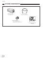
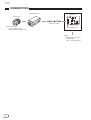
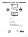
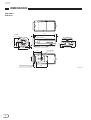
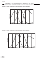
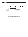
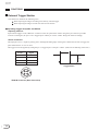
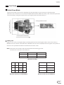
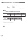
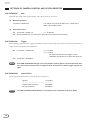
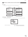
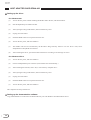
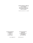
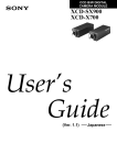
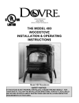
CCD COLOR DIGITAL
CAMERA MODULE
DFW-SX900
DFW-X700
Technical
Manual
(Ver. 1.0)
English
DFW-SX900
DFW-X700
Table of Contents
OUTLINE ..................................................................................................................... 1
MAIN FEATURES ...................................................................................................... 1
SYSTEM COMPONENTS .......................................................................................... 2
SPECIFICATIONS ...................................................................................................... 3
CONNECTION ............................................................................................................ 4
NAMES AND FUNCTIONS OF PARTS ................................................................... 5
DIMENSIONS ............................................................................................................. 6
CCD PIXEL LOCATION ............................................................................................ 7
SPECTRAL CHARACTERISTICS (TYPICAL VALUES) ....................................... 8
FUNCTIONS ................................................................................................................ 9
SETTINGS OF CAMERA CONTROL AND STATUS REGISTER ......................... 20
COMMAND SENDING PROCEDURE UNTIL IMAGES ARE DISPLAYED ........ 33
COMMAND SETTING AND OPERATION TIMING .............................................. 38
SUPPLEMENTS .......................................................................................................... 41
HOST ADAPTER CARD DFWA-400 ........................................................................ 42
DFW-SX900
DFW-X700
OUTLINE
The DFW-SX900/X700 is a C-mounted color digital video camera utilizing a 1/2-type PS IT CCD. The IEEE1394-1995 digital
interface realizes a transfer speed of 400M bps and outputs of SXGA (1,280 × 960)/YUV (4 : 2 : 2)/7.5 fps with the DFW-SX900,
XGA (1,024 × 768)/YUV (4 : 2 : 2)/15 fps with the DFW-X700. In addition, the DFW-SX900/X700 also adopts a primary color
filter CCD to realize good color reproductivity, as well as a square pixel CCD to eliminate the need for aspect ratio conversion in
the image processor.
MAIN FEATURES
1/2-type progressive scan IT CCD
Primary color filter/square pixel/progressive scan CCD
Non-compressed YUV (4 : 2 : 2) 8 bits each
External trigger function
The external trigger shutter function allows the image exposure to be coordinated with external equipment and moving
objects. The exposure time can be controlled via software over the IEEE1394 bus.
Solid aluminum diecasting chassis
Partial scan/output of images is possible by the partial scan function
1
DFW-SX900
DFW-X700
SYSTEM COMPONENTS
Video Camera Module
DFW-SX900/X700
IEEE1394 Cable
(6-pin, 4.5 m) (Accessory)
C-mount Lens (Option)
• J6 × 11 MACRO (Canon)
• 25MM HD LENS VF2509 (Canon)
Host Adapter Card (Option)
DFWA-400
2
DFW-SX900
DFW-X700
SPECIFICATIONS
Image sensor
Number of effective pixels
DFW-SX900
DFW-X700
Output image size (Max.)
DFW-SX900
DFW-X700
Interface format
Protocol
Data format
DFW-SX900
DFW-X700
: 1/2-type progressive scan CCD
: Approx. 1.45M pixels
: Approx. 800K pixels
:
:
:
:
1,280 (H) × 960 (V)
1,024 (H) × 768 (V)
IEEE1394-1995
1394-based Digital Camera Specification Version 1.30
: 1,280 × 960
1,024 × 768
800 × 600
640 × 480
320 × 240
: 1,024 × 768
800 × 600
640 × 480
320 × 240
Frame rate
:
DFW-SX900
:
DFW-X700
:
Transfer speed
:
Lens mount
:
Flange back
:
Minimum illumination
:
White balance
:
HUE
:
Saturation
:
Brightness
:
Gamma
:
CCD iris
:
Shutter
:
Gain
:
External trigger shutter
Minimum unit in partial scan mode
:
DFW-SX900
:
DFW-X700
:
Supply voltage
:
Power consumption
:
Operating temperature
:
Storage temperature
:
Operating relative humidity
:
Storage relative humidity
:
Dimensions
:
Mass
:
Accessories
1,392 (H) × 1,040 (V)
1,034 (H) × 779 (V)
YUV (4 : 2 : 2)
YUV (4 : 2 : 2)
YUV (4 : 2 : 2)
YUV (4 : 2 : 2)
YUV (4 : 2 : 2)
YUV (4 : 2 : 2)
YUV (4 : 2 : 2)
YUV (4 : 2 : 2)
YUV (4 : 2 : 2)
3.75, 7.5 fps
7.5, 15 fps
400M, 200M bps
C-mount
17.526 mm
20 lx (F1.4, Gain: +18 dB)
One Push/ATW/Preset (3,200 K, 5,600 K)/Manual
Adjustable
Adjustable
Adjustable
Switchable between three positions including OFF
ON/OFF
2s to 1/20,000s
Auto/Manual (0 to 18 dB)
Available
320 (H) × 240 (V)
512 (H) × 192 (V)
DC +8 to +30 V (from IEEE1394 cable)
3.3 W (at 12 V)
–5 to +45°C
–20 to +60°C
20 to 80% (No condensation)
20 to 95% (No condensation)
55 (W) × 50 (H) × 110 (D) mm
250 g
IEEE1394 cable (1), Lens mount cap (1), Clamp filter (2)
External trigger connector (male) (1), Operating Instructions (1)
3
DFW-SX900
DFW-X700
CONNECTION
DFW-SX900/X700
DFWA-400
C-mount Lens
IEEE1394 Cable
Recommended Lens:
• J6 × 11 MACRO (Canon)
• 25MM HD LENS VF2509 (Canon)
Host Adapter Card
Host Equipment (PC, etc.)
Display
Must be above 17-inch and
compatible with
1,280 × 1,024 display mode
4
DFW-SX900
DFW-X700
NAMES AND FUNCTIONS OF PARTS
2
6
1
4
7
3
5
q Lens mount (C-mount)
w Flange back hole
Adjust the flange back using a standard head screwdriver.
e Pilot lamp
Blinks in green when the power is turned on, and in orange in the isochronous
transmission (enabled) state.
r Screw hole for tripod mounting
t Camera fixing reference holes
y TRIG IN (Trigger) connector
Inputs the TTL level, negative polarity trigger signal.
u Camera connector (IEEE1394 connector)
Connect to the host equipment using the IEEE1394 cable provided.
y Pin assignment of TRIG IN connector (female)
1. NC
2. GND
3. TRIG IN
4. NC
4
1
3
2
u Pin assignment of camera connector
1. Power
2. Power (GND)
3. TPB–
4. TPB+
5. TPA–
6. TPA+
2
4
6
1
3
5
5
DFW-SX900
DFW-X700
DIMENSIONS
DFW-SX900
DFW-X700
110
3.5
55
1
16.55
25.5
50
5
33.4
1" -32UNC
41
25
1/4" -20UNC
4-M3 (Effective Depth)
13
56
Unit: mm
6
DFW-SX900
DFW-X700
CCD PIXEL LOCATION
Top View
DFW-SX900
Total number of pixels
: 1,434 (H) × 1,050 (V)
Number of effective pixels: 1,392 (H) × 1,040 (V)
Number of output pixels : 1,280 (H) × 960 (V)
Unit cell size
: 4.65 µm (H) × 4.65 µm (V)
Output Pixel Area
2
V
1040
960
56
1280
40
8
1392
2
40
Effective Pixel Area
H
DFW-X700
Total number of pixels
: 1,077 (H) × 788 (V)
Number of effective pixels: 1,034 (H) × 779 (V)
Number of output pixels : 1,024 (H) × 768 (V)
Unit cell size
: 6.25 µm (H) × 6.25 µm (V)
Output Pixel Area
2
V
779
768
5
1024
6
7
3
1034
40
Effective Pixel Area
H
7
DFW-SX900
DFW-X700
SPECTRAL CHARACTERISTICS (TYPICAL VALUES)
Example of spectral characteristics of CCD image sensor used for DFW-SX900
G
R
Relative Response
B
400
500
600
700
Wavelength [nm]
Example of spectral characteristics of CCD image sensor used for DFW-X700
G
B
Relative Response
R
350
400
450
500
550
Wavelength [nm]
8
600
650
700
DFW-SX900
DFW-X700
FUNCTIONS
The DFW-SX900/X700 differs from the conventional analog camera in that no video signals will be output by just supplying
power. It will start operating when designated commands are written in the CSR (Control & Status Register) specified in the
1394-based Digital Camera Specification Ver.1.30. For details on the steps to video signal output and details of CSR, refer to
“SETTINGS OF CAMERA CONTROL AND STATUS REGISTER” on page 20 and “COMMAND SENDING PROCEDURE
UNTIL IMAGES ARE DISPLAYED” on page 33.
This chapter describes the functions of the camera which can be set using the CSR.
Camera Functions
Video Format
Image sizes supported are as follows.
(X7 indicates the Video Format, Video Mode, and Frame Rate supported by the DFW-X700. S9 indicates the Video Format,
Video Mode, and Frame Rate supported by the DFW-SX900.)
Format_0
Mode
Video Format
Mode_0
160 × 120
YUV (4 : 4 : 4)
Mode_1
320 × 240
YUV (4 : 2 : 2)
Mode_2
640 × 480
YUV (4 : 1 : 1)
Mode_3
640 × 480
YUV (4 : 2 : 2)
Mode_4
640 × 480
RGB
Mode_5
640 × 480
Y (Mono)
60 fps
30 fps
15 fps
7.5 fps
3.75 fps
X7
X7/S9
S9
X7
X7/S9
S9
15 fps
7.5 fps
3.75 fps
X7
X7/S9
S9
X7
X7/S9
S9
15 fps
7.5 fps
3.75 fps
S9
S9
Mode_6
Mode_7
Format_1
Mode
Video Format
Mode_0
800 × 600
YUV (4 : 2 : 2)
Mode_1
800 × 600
RGB
Mode_2
800 × 600
Y (Mono)
Mode_3
1,024 × 768
YUV (4 : 2 : 2)
Mode_4
1,024 × 768
RGB
Mode_5
1,024 × 768
Y (Mono)
60 fps
30 fps
1.875 fps
Mode_6
Mode_7
Format_2
Mode
Video Format
Mode_0
1,280 × 960
YUV (4 : 2 : 2)
Mode_1
1,280 × 960
RGB
Mode_2
1,280 × 960
Y (Mono)
Mode_3
1,600 × 1,200 YUV (4 : 2 : 2)
Mode_4
1,600 × 1,200 RGB
Mode_5
1,600 × 1,200 Y (Mono)
60 fps
30 fps
1.875 fps
Mode_6
Mode_7
9
DFW-SX900
DFW-X700
FUNCTIONS
Gain
Used for setting the gain of the video signal amplifier. The gain can be set to 180 steps between the standard gain and
maximum +18 dB. (1 step is not 0.1 dB.)
By setting AUTO to ON, the gain will be automatically adjusted to the appropriate exposure. The range of operations is 0 to
+18 dB.
Shutter
The CCD exposure time can be set between the maximum 2 seconds and minimum 1/20,000 seconds. By setting AUTO to
ON, the exposure time will be automatically adjusted to the appropriate exposure.
Auto Exposure
Used for setting the exposure compensation for when Gain or Shutter or both are operating in the AUTO mode. When both
Gain and Shutter are set to Manual, the Auto Exposure setting will be invalid. The range of operations is about –1EV to
+0.5EV.
If both Gain and Shutter are operated in the AUTO mode by Auto Exposure, the ranges of operations of both are as follows.
(However, these values are approximate values and may differ according to the adjusted and operating states of the camera.)
EV7
EV10
AGC
EV17* (SX900)
CCD IRIS
* EV16 for X700
Brightness
The brightness of images can be controlled by changing the black level setting. Adjust the brightness if the appropriate
gradation cannot be obtained due to the blurring of the black portions of the image.
The range of settings is about 0 to 75 (when gamma is ON (1) in full range 255).
10
DFW-SX900
DFW-X700
FUNCTIONS
Gamma
Used for setting gamma compensation to OFF, ON (1), or ON (2).
OFF : Outputs CCD signals for image processing linearly.
ON (1) : For obtaining natural gradation taking into account the characteristics of the monitor.
ON (2) : For obtaining three-dimensional images with a subject that has a small luminance dynamic range.
Gamma ON (2)
Output
Gamma ON (1)
Gamma OFF
Input
Concept of Gamma Characteristics
Sharpness
Used for adjusting sharpness of the image.
The sharpness can be changed by about more than 200% from the factory setting.
White Balance
Used for adjusting white balance by adjusting R-gain and B-gain. White subjects can be shot in white by setting the white
balance according to the color temperature of the luminance light. The White Balance operation mode can be selected from
three modes – Manual, One Push, and ATW. The range of operations of each mode is as follows.
Manual : 2,400 to 10,000 K or more
One Push : 2,400 to 10,000 K or more
ATW
: 2,650 to 6,000 K or more (Excluding fluorescent light)
Color Temperature
This function was originally intended for selecting the optical filter. However with the DFW-SX900/X700, the R-gain and Bgain are set to the appropriate White Balance when color temperatures 3,200 K and 5,600 K light sources are used.
Hue
Used for adjusting the hue of the image.
The hue can be changed by about more than ±15 degrees from the rotary angle of the NTSC Vector Scope luminance scope
based on the factory setting.
11
DFW-SX900
DFW-X700
FUNCTIONS
Saturation
Used for adjusting the saturation of the image.
The saturation can be changed by about more than 150% from the factory setting.
Isochronous Start/Stop
Used for turning ON/OFF the output of IEEE1394 isochronous transmitted images. When image output is set to ON, the LED
in front of the camera will light up in orange.
One Shot
Used for outputting only one image data (one frame) in the Isochronous OFF state. The difference between this function and
Trigger described on the next section is that image input is started by the IEEE1394 command instead of external trigger
signals. The timing at which exposure starts is also undefined (within 133.3 ms after the command is received with
DFW-SX900 and within 66.7 ms with DFW-X700).
The LED in front of the camera lights up in orange when image data is isochronously transmitted by the One Shot function.
Trigger
Used for setting the external trigger mode to ON or OFF. No moving image signals are output in this mode.
Isochronous output is stopped at the point Trigger ON is set even in the Isochronous Start state. When external trigger pulses
(TTL level, negative polarity, pulse width above 1 ms) are input, one image (one frame) exposed for the specified time
(specified at the shutter) will be output from that instant. The time to the start of image data output after the external trigger
pulse is input can be changed according to the exposure time.
Paint
Used for changing the R-gain and B-gain by only the values specified at R-offset and B-offset respectively in the use of One
Push White Balance. Use of this function is recommended when not adjusting White Balance to white. For example, when
viewing a subject on the white 6,800 K monitor using a 3,200 K light source, this function can be used to adjust colors on the
monitor to the same state as viewing a subject with the naked eye using a 3,200 K light source.
Y/Cr/Cb → R/G/B conversion
The DFW-SX900/X700 outputs Y/Cr/Cb signals as digital image signals.
The equations for converting these signals to R/G/B signals are as follows.
R ≈ 1.4022Cr + Y
B ≈ 1.7710Cb + Y
G ≈ Y – 0.7144Cr – 0.3457Cb
12
DFW-SX900
DFW-X700
FUNCTIONS
Operations in Normal Mode
Exposure and readout are repeated according to the VD pulses inside the camera. As the operating timing of the camera
differs according to the frame rate, it is described below.
The frame rates are shown in the following table.
Camera
DFW-SX900
DFW-X700
When power on
When frame rate is reduced
7.5 fps = approx. 133 ms
3.75 fps = approx. 267 ms
15 fps = approx. 67 ms
7.5 fps = approx. 133 ms
When exposure time is 1 frame or shorter
VDs are generated continuously inside the camera and images are sent accordingly. The images are output at the cycle of the
frame rate set.
VD
Inside Camera
SUB
SG
,
A
Isochronous
C
Front Panel LED
B
Exposure Time
Green
Green
Orange
Orange
Green
Orange
Operations in Normal Mode
For the image output timing based on the falling edge of VDs generated inside the camera, image data output starts at the point
the A period is passed, and the image data is output during the B period.
Camera
DFW-SX900 (7.5 fps)
DFW-X700
(15 fps)
A [ms]
B [ms]
C [ms]
Approx. 8
Approx. 120
Approx. 13
Approx. 2.4
Approx. 64
Approx. 2.6
Time until Data is Read Out and Output Period of Data
13
DFW-SX900
DFW-X700
FUNCTIONS
When the output frame rate is reduced (3.75 fps of DFW-SX900, 7.5 fps of DFW-X700), images will be read out from the
CCD for every VD. However, as every other image is used, the images read out during the isochronous output period will not
be used.
VD
Inside Camera
SUB
SG
,,,
B
Exposure Time
A
Isochronous
C
Green
Green
Front Panel LED
Orange
Orange
Operations When Frame Rate is Reduced
Camera
A [ms]
B [ms]
C [ms]
Approx. 8
Approx. 240
Approx. 26
Approx. 2.4
Approx. 128
Approx. 5
DFW-SX900 (3.75 fps)
DFW-X700
(7.5 fps)
Time until Data is Read Out and Output Period of Data
When exposure time is over 1 frame
When exposure time over 1 frame is specified (extended exposing mode), the A period until images are output from the VDs
and B period outputting images are the same as the above case. However, as no images are output during the exposure time,
the actual frame rate will drop.
VD
Inside Camera
SUB
SG
Exposure Time
,
B
A
Isochronous
Front Panel LED
Green
Green
Orange
Orange
Operations in Extended Exposing Mode (In the Case of 2 Frames)
Camera
DFW-SX900 (7.5 fps)
DFW-X700
(15 fps)
A [ms]
B [ms]
Approx. 8
Approx. 120
Approx. 2.4
Approx. 64
Time until Data is Read Out and Output Period of Data
14
DFW-SX900
DFW-X700
FUNCTIONS
When the frame rate is reduced in the extended exposing mode, the timing will be as follows.
VD
Inside Camera
SUB
SG
Exposure Time
,,
B
A
Isochronous
Green
Front Panel LED
Green
Orange
Operations in Extended Exposing Mode (In the Case of 2 Frames) When Frame Rate is Reduced
Camera
DFW-SX900 (3.75 fps)
DFW-X700
(7.5 fps)
A [ms]
B [ms]
Approx. 8
Approx. 240
Approx. 2.4
Approx. 128
Time until Data is Read Out and Output Period of Data
15
DFW-SX900
DFW-X700
FUNCTIONS
External Trigger Shutter
This function is useful for the following cases.
When capturing the images according to an arbitrary external trigger
When capturing the images at same time with several cameras
Inputting trigger and pulse conditions
<Inputting method>
Input external triggers to the “TRIG IN” connector on the rear panel of the camera using the 4-pin connector provided.
As shown in the figure, the pin 3 is the “Trigger Input” and the pin 2 is the “GND”. Design the cable accordingly.
<Pulse conditions>
The input pulse is a 5 V negative polarity pulse. Although the falling edge of the signal is detected as the start of trigger, the
pulse width must be set 1 ms or more.
The trigger can be also applied by setting the pin 3 “Trigger Input” to the pin 2 “GND”. (Take note of chattering at this time.)
Pin No.
Signal
#1
NC
#2
GND
#3
TRIG IN
#4
NC
Min. 1 ms
5V
Trigger Pulse
4
1
HRS
3
2
TRIG IN Connector (Rear Panel View)
16
DFW-SX900
DFW-X700
FUNCTIONS
Internal operations of camera in trigger shutter operation mode
An about 3 µs width SUB pulse is generated immediately after trigger is input. Signals accumulated in the CCD sensor until
then are eliminated, after which exposure is started. After the exposure time based on the shutter speed set passes, VD is
generated inside the camera. (Specifically, VD is generated about 10 µs before exposure ends.)
After the A period passes from the falling edge of the VD, images are output during the B period.
Trigger Acceptance Prohibition Period
TRIGGER
SUB
VD
Inside Camera
SG
D
CCD OUT
Exposure
Time
A
B
Isochronous
Front Panel LED
Green
Green
Orange
External Trigger Shutter Operations
Camera
DFW-SX900 (7.5 fps)
DFW-X700
(15 fps)
A [ms]
B [ms]
D [ms]
Approx. 8
Approx. 120
Approx. 4.2
Approx. 2.4
Approx. 64
Approx. 0
Time until Data is Read Out and Output Period of Data
17
DFW-SX900
DFW-X700
FUNCTIONS
The trigger acceptance prohibition period continues until all of CCD image has been transferred out of the camera.
When the transfer frame rate is reduced (3.75 fps of DFW-SX900, 7.5 fps of DFW-X700), data will continue to be transferred
even after readout of image has been completed as shown in the figure below. The trigger prohibition period continues until
data transfer ends.
All trigger inputs to the camera during the “Trigger Acceptance Prohibition Period” will be ignored.
The following equation is one method of roughly calculating the acceptable trigger interval.
Trigger interval = Exposure time + Frame rate
Exposure Time
Camera
1/1,000s
1/100s
DFW-SX900 (When set to 7.5 fps)
Approx. 134 ms
Approx. 143 ms
DFW-X700 (When set to 15 fps)
Approx. 68 ms
Approx. 77 ms
Example of Acceptable Trigger Interval
Trigger Acceptance Prohibition Period
TRIGGER
SUB
VD
Inside Camera
SG
CCD OUT
Exposure
Time
A
B
Isochronous
Front Panel LED
Green
Green
Orange
External Trigger Shutter Operations When Frame Rate is Reduced
18
DFW-SX900
DFW-X700
FUNCTIONS
Partial Scan Mode
The partial scan mode is a function for outputting part of the full images a region of interest on the whole image.
When the screen size needs to be set to the full size (DFW-SX900: SXGA, DFW-X700: XGA), data volume and system load
can be decreased by setting the required screen size using the partial scan mode (Format_7).
Vertical (Vertical Direction)
Cutting by partial scan mode
Horizontal (Horizontal Direction)
Cutting size
Images can be cut only in rectangular shapes (including squares) and not with irregular features (convex and concave).
Minimum unit size is shown in the table below. Minimum unit sizes can be combined and cut out together. The position of
each unit can be specified but should not exceed the full size of the screen.
Note) This function can be used in both the normal mode and external trigger mode.
The frame rate is the same as the normal rate.
Camera
Horizontal Size
Vertical Size
DFW-SX900
320
240
DFW-X700
512
192
Minimum Unit Size
Minimum Unit Size for DFW-SX900
Minimum Unit Size for DFW-X700
19
DFW-SX900
DFW-X700
SETTINGS OF CAMERA CONTROL AND STATUS REGISTER
This chapter describes CSR addresses using the lower 32 bits of 64 bits. (CSR: Abbreviation of Control and Status Register)
The omitted upper 32 bits are ∗∗∗∗FFFFh. (∗∗∗∗ changes according to the connection of the IEEE1394 Serial Bus.)
Read/Write of the CSR is executed in units of Quadlet (4 bytes). The CSR address is the address of the leading byte of the
Quadlet.
When describing the 32-bit command set for CSR in Hex, bit 0 is described as MSB (Most Significant Bit).
Example :
82012345h = 10000010 00000001
:
bit 0
00100011
01000101b
:
bit 31
=======================================================================
CSR F0F00000h
Camera Initialize Register (Write Only)
Executes the same operations as when Factory Setup was selected in Current Memory Channel of CSR F0F00624h.
Command: 80000000h
Resets the CSR F0F00800hth functions to factory settings.
At this time, return the CSR F0F00624h Current Mem. ch also to “0”.
=======================================================================
CSR F0F00600h to F0F00624h control isochronous image transmission, and load/save settings of the camera.
CSR F0F00600h
Current Frame Rate
Specify the Frame Rates 1 to 3.
Frame Rate
Command
---------------------------------------------------1 (3.75 fps)
20000000h
2 (7.5 fps)
40000000h
3 (15 fps)
60000000h
NOTE :
20
Set when CSR F0F00614h Iso_EN is OFF (STOP).
According to the settings of the CSR F0F0081Ch Shutter, isochronous transmission may
be carried out at a lower rate than the frame rate set here.
In the Trigger mode, the frame rate set here will not be effective. (As it depends on the
cycle of the trigger signal.)
DFW-SX900
DFW-X700
SETTINGS OF CAMERA CONTROL AND STATUS REGISTER
CSR F0F00604h
Current Video Mode
Specify the Video Modes 0 to 3.
Video Mode
Command
---------------------------------------------------0
00000000h
1
20000000h
2
40000000h
3
60000000h
NOTE : Set when CSR F0F00614h Iso_EN is OFF (STOP).
CSR F0F00608h
Current Video Format
Specify the Video Format.
Video Format
Command
--------------------------------------------------0
00000000h
1
20000000h
2
40000000h
7
E0000000h
NOTE : Set when CSR F0F00614h Iso_EN is OFF (STOP).
21
DFW-SX900
DFW-X700
SETTINGS OF CAMERA CONTROL AND STATUS REGISTER
CSR F0F0060Ch
Isochronous Channel, Transmit Speed
Specify Isochronous Channel (0 – 0Fh), Transmit Speed (200M, 400M bps).
Speed
Command
--------------------------------------------------1 (200M bps)
n1000000h
2 (400M bps)
n2000000h
n: Isochronous Channel 0 – Fh
NOTE :
Set when CSR F0F00614h Iso_EN is OFF (STOP).
The minimum Transmit Speed which can be selected differs according to Video Format,
Video Mode, and Frame Rate. Set according to the following table.
DFW-SX900
Format0
Frame Rate
Format2
Format1
mode1
mode3
mode0
mode3
mode0
3.75
200M bps
200M bps
200M bps
200M bps
200M bps
7.5
200M bps
200M bps
200M bps
200M bps
400M bps
DFW-X700
Format0
Frame Rate
Format1
mode1
mode3
mode0
mode3
7.5
200M bps
200M bps
200M bps
200M bps
15
200M bps
200M bps
200M bps
400M bps
CSR F0F00614h
Isochronous Transmission Start/Stop
Set the Start/Stop of image transmission by Isochronous.
Start : Command = 80000000h
Stop : Command = 00000000h
NOTE : Before setting Start of image transmission, set the CSR F0F00600h – F0F0060Ch.
22
DFW-SX900
DFW-X700
SETTINGS OF CAMERA CONTROL AND STATUS REGISTER
CSR F0F00618h
Memory Save
The current settings of the camera using commands CSR F0F00600h – F0F0060Ch, CSR F0F00620h, and CSR
F0F00800hth are memorized in the Memory Channel specified by CSR F0F00620h.
The settings will be preserved in the memory even when the camera power is turned off.
Execute: Command = 80000000h
NOTE :
CSR F0F0061Ch
Before setting Execute, set the CSR F0F00620h Memory Save Channel.
Memory Save requires about one second to execute. After setting, do not write other
commands for one second.
One Shot
Perform the isochronous transmission of images for only one frame.
Execute: Command = 80000000h
NOTE :
CSR F0F00620h
Can be used only when CSR F0F00614h Iso_EN is OFF (STOP).
Do not set a new One Shot command until isochronous transmission completes after
setting the One Shot command to CSR.
Memory Save Channel
Specify the Memory Channel (ch1, ch2) for memorizing the current camera settings.
ch1: Command = 10000000h
ch2: Command = 20000000h
CSR F0F00624h
Current Memory Channel
Read out the camera settings (ch1, ch2) memorized by the CSR F0F00618h Memory Save or the factory settings (Factory)
from the memory, and set in the camera.
The Memory Channel that was specified last will be automatically memorized. When the power is turned ON the next
time, the settings memorized in this Memory Channel will be effective.
Channel
Command
--------------------------------------------------Factory
00000000h
ch1
10000000h
ch2
20000000h
23
DFW-SX900
DFW-X700
SETTINGS OF CAMERA CONTROL AND STATUS REGISTER
=======================================================================
CSR F0F00800h to F0F0088Ch control the various functions of the camera.
CSR F0F00800h
Brightness
Adjust the black level of the image.
Command = 820000nnh
CSR F0F00804h
nn: Adjust in the range of 60h (dark) – DFh (bright).
60h is the standard value.
Auto Exposure
Adjust the exposure compensation of Auto Exposure.
Command = 820000nnh
nn: Adjust in the range of 00h (under) – FFh (over).
80h is the standard value.
NOTE : Auto Exposure will not be effective unless either Shutter or Gain is set to Auto.
CSR F0F00808h
Sharpness
Adjust the sharpness of the image contour.
Command = 820000nnh
24
nn: Adjust in the range of 00h (soft) – 07h (sharp).
03h is the standard value.
DFW-SX900
DFW-X700
SETTINGS OF CAMERA CONTROL AND STATUS REGISTER
CSR F0F0080Ch
White Balance
Adjust the red and blue gains to capture white subjects in color properly. Two types of automatic adjustment modes are
available.
NOTE :
(1)
If the CSR F0F00830h Trigger is set to ON or if the CSR F0F0081Ch Shutter setting is less
than 800h, the Auto function cannot be used.
The CSR F0F0088Ch Optical Filter is canceled by this command. (Priority to latter)
Manual adjustment
Command = 820mm0nnh
(2)
mm: Adjust B-gain in the range of 00h (min) – FFh (max).
nn : Adjust R-gain in the range of 00h (min) – FFh (max).
80h is the standard value.
One-Push Auto White Balance
Perform automatic adjustment when command is received to maintain the white balance at that time.
Execute: Command = 86∗∗∗∗∗∗h
∗∗∗∗∗∗: Undefined
When this operation is complete, the command is read out as 82∗∗∗∗∗∗h (∗∗∗∗∗∗: Undefined).
NOTE :
(3)
Execute after capturing a white subject lit using the light source used for shooting
over the whole screen at the appropriate exposure. It will take 10 seconds at
maximum to complete automatic adjustment.
Execute again if the light source used for shooting has been changed.
Auto Tracing White Balance
Perform automatic adjustment continuously to trace the white balance according to changes in the shooting
conditions.
Execute : Command = 83∗∗∗∗∗∗h
∗∗∗∗∗∗: Undefined
Stop
: Stop operations according to the following rules.
q Read out the CSR F0F0080Ch.
w Write the manual adjustment command at the value read out.
820mm0nnh
Set the values read out for mm, nn.
NOTE : Operations stop if the exposure is inappropriate.
25
DFW-SX900
DFW-X700
SETTINGS OF CAMERA CONTROL AND STATUS REGISTER
CSR F0F00810h
Hue
Adjust the hue of the image.
Command = 820000nnh
CSR F0F00814h
nn: Adjust in the range of 53h (right edge) – ADh (left edge).
80h is the standard value.
Saturation
Adjust the saturation of the image.
Command = 820000nnh
CSR F0F00818h
nn: Adjust in the range of 00h (light) – FFh (deep).
80h is the standard value.
Gamma
Set the gamma characteristics.
Gamma
Command
--------------------------------------------------OFF
82000080h
ON (1)
82000081h
ON (2)
82000082h
26
81h is the standard value.
DFW-SX900
DFW-X700
SETTINGS OF CAMERA CONTROL AND STATUS REGISTER
CSR F0F0081Ch
Shutter
Set the exposure time of the electronic shutter. Auto exposure (CCD IRIS) can be also set.
(1)
Manual adjustment
Command = 82000nnnh
<When DFW-SX900>
nnn: Adjust in the range of 7F1h (long) – C2Dh (short).
B22h (1/30 sec) is the standard value.
2.0 sec ≥ Shutter Speed ≥ 1/7.5 sec
nnn = 800h – 7.5 ∗ Shutter Speed (sec)
1/7.5 sec > Shutter Speed ≥ 1/5,882 sec
nnn = 3116.4 – 7999 ∗ Shutter Speed (sec)
Shutter Speed = 1/10,000 sec
nnn = C2Ch
Shutter Speed = 1/20,000 sec
nnn = C2Dh
<When DFW-X700>
nnn: Adjust in the range of 7E2h (long) – B20h (short).
992h (1/30 sec) is the standard value.
2.0 sec ≥ Shutter Speed ≥ 1/15 sec
nnn = 800h – 15 ∗ Shutter Speed (sec)
1/15 sec > Shutter Speed ≥ 1/8,361 sec
nnn = 2848.4 – 11962 ∗ Shutter Speed (sec)
Shutter Speed = 1/20,000 sec
nnn = B20h
NOTE : When nnn < 800h, do not turn ON the Gain and White Balance Auto functions.
(2)
Auto exposure (CCD IRIS)
ON : Command = 83000∗∗∗h
∗∗∗: Undefined
OFF : Specify 82000mmmh. (Or read out the shutter speed once and rewrite the value.)
NOTE : When the CSR F0F00830h Trigger is ON, do not set Auto exposure to ON.
(3)
Shutter OFF
Command = 80000000h
At this time, the shutter speed will be 1/30 seconds.
27
DFW-SX900
DFW-X700
SETTINGS OF CAMERA CONTROL AND STATUS REGISTER
CSR F0F00820h
Gain
Adjust the gain of the video signal amplifier. Auto Gain Control can be also set.
(1)
Manual adjustment
Command = 82000nnnh
(2)
nnn: Adjust in the range of 800h (min) – 8B4h (max).
800h is the standard value.
Auto Gain Control
ON : Command = 83000∗∗∗h
∗∗∗: Undefined
OFF : Specify 82000nnnh. (Or read out the gain value once and rewrite the value.)
CSR F0F00830h
Trigger
When inputting a negative polarity signal to the TRIG IN connector at the back of the camera, isochronous transmission of
images for only one frame will be performed.
ON : Command = 8200mnnnh
m = 0: mode0
m = 3: mode3
nnn becomes effective and trigger is input
repeatedly at intervals 10 ms times the value set.
OFF : Command = 80000000h
NOTE : If the CSR F0F00600th settings are not set properly and Iso_EN is not ON at the same time,
no isochronous transmission of images will be executed even when trigger signals are
input.
CSR F0F0088Ch
Optical Filter
Set the appropriate white balance preset for the main light source.
Lighting
Command
-------------------------------------------------------------tungsten lamp (3,200 K)
82000000h
day light (5,600 K)
82000001h
NOTE : The CSR F0F0080Ch White Balance is canceled by this command. (Priority to latter)
28
DFW-SX900
DFW-X700
SETTINGS OF CAMERA CONTROL AND STATUS REGISTER
=======================================================================
For Format7
When using Format7, parameters need to be set as shown in the following figure.
Application
Camera
Set parameters
ISO_Speed
IMAGE_POSITION
IMAGE_SIZE
COLOR_CODING_ID
Calculate parameters
PIXEL_NUMBER_INQ
TOTAL_BYTES_HI:LO_INQ
PACKET_PARA_INQ
RecBytePerPacket field
Set parameters
BytePerPacket field
Calculate parameters
TOTAL_BYTES_HI:LO_INQ
PacketPerFrame_INQ
ISO_EN < –1
CSR F1000108h
VIDEO starts
Image Position
Specify the coordinates at the top left of the screen when cutting one part of the screen by the partial scan function.
y
x
(x, y)
Command = 0mmm0nnnh
mmm: X coordinate pixel number (hexadecimal)
nnn : Y coordinate pixel number (hexadecimal)
29
DFW-SX900
DFW-X700
SETTINGS OF CAMERA CONTROL AND STATUS REGISTER
CSR F100000Ch
Image Size
Set the size of the area when cutting one part of the screen by the partial scan function.
Minimum Unit for DFW-SX900
Minimum Unit for DFW-X700
Set the size of the area using the width and height of the rectangular area composed of the minimum units in the above
figure.
0
1/2
x
This area is 1/4 the width and 1/2 the height
of the whole screen.
1/2
y
<When DFW-SX900>
Command = 0iii0jjjh
iii: Width of area
Width (x)
iii
--------------------------------------------------------1/4 of whole screen
140h (320)
1/2 of whole screen
280h (640)
3/4 of whole screen
3C0h (960)
Whole screen
500h (1,280)
<When DFW-X700>
Command = 0iii0jjjh
1/2 of whole screen
Whole screen
30
Height (y)
jjj
-------------------------------------------------------1/4 of whole screen
0F0h (240)
1/2 of whole screen
1E0h (480)
3/4 of whole screen
2D0h (720)
Whole screen
3C0h (960)
iii: Width of area
Width (x)
iii
--------------------------------------------------------200h (512)
400h (1,024)
jjj: Height of area
jjj: Height of area
Height (y)
jjj
-------------------------------------------------------1/4 of whole screen
0C0h (192)
1/2 of whole screen
180h (384)
3/4 of whole screen
240h (576)
Whole screen
300h (768)
DFW-SX900
DFW-X700
SETTINGS OF CAMERA CONTROL AND STATUS REGISTER
Limitations : Set the area so that the bottom right of the rectangular area does not exceed the screen size.
When the CSR F1000108h Image Position is set to 0mmm0nnnh (mmm: X coordinates, nnn: Y
coordinates), set the rectangular area so as to satisfy following two equations.
When DFW-SX900
mmm + iii ≤ 500h
nnn + jjj ≤ 3C0h
(Max Image Size: Hmax)
(Max Image Size: Vmax)
When DFW-X700
mmm + iii ≤ 400h
nnn + jjj ≤ 300h
(Max Image Size: Hmax)
(Max Image Size: Vmax)
NOTE : Set when CSR F0F00614h Iso_EN is OFF (STOP).
CSR F1000110h
Color Coding ID
Set the Color Coding ID when cutting one part of the screen by the partial scan function.
As both the DFW-SX900 and DFW-X700 support only Color Coding ID 2 (YUV: 422), always set ID 2.
Command = 02000000h
NOTE : Set when CSR F0F00614h Iso_EN is OFF (STOP).
CSR F1000144h
Byte per Packet
Set the Byte per Packet according to the value specified by CSR F1000140h Packet Para Inq.
When CSR F1000108h (Image Position) and CSR F100000Ch (Image Size) are set, the camera calculates the CSR
F1000140h Packet Para Inq. Packet Para Inq specifies the maximum value and minimum unit of Byte per Packet.
When CSR F1000140h value is 0mmm0nnnh, set the command = 0iii0000h to CSR F1000144h.
mmm: Minimum unit
nnn : Maximum value
iii
: Integral multiple of the minimum unit which does
not exceed the maximum value.
31
DFW-SX900
DFW-X700
SETTINGS OF CAMERA CONTROL AND STATUS REGISTER
General precautions for partial scan function
When settings of CSR related to partial scan mode (F0F0060Ch, F1000008h, F100000Ch, F1000010h) are changed, the
camera will recalculate the specified value of CSR F1000140h Packet Para Inq each time.
If incorrect settings are performed for CSR related to partial scan mode with the CSR F0F00614h Iso_EN in the ON state,
isochronous transmission will be prohibited. In this case, set the correct settings for the CSR related to partial scan mode.
32
DFW-SX900
DFW-X700
COMMAND SENDING PROCEDURE UNTIL IMAGES ARE DISPLAYED
(1)
Acquiring the camera control register base address
Read out the Configuration ROM and acquire the base address of the camera control register.
The base address of the Configuration ROM is FFFF F0000000H.
Bus Info Block
Root Directory
Offset
0–7
8 – 15
16 – 23
24 – 31
400H
04
1F
CE
D4
404H
31
33
39
34
408H
20
FF
60
00
40CH
08
00
46
20
410H
00
07
414H
00
04
C8
0A
418H
03
08
00
46
41CH
0C
00
83
C0
420H
8D
00
00
02
424H
D1
00
00
04
Serial No.
Obtain the offset address for Node Uniq ID Leaf
420H + 000002H ∗ 4 = 428H
Obtain the offset address for Unit Directory
424H + 000004H ∗ 4 = 434H
Node Uniq ID Leaf
428H
00
02
E7
33
42CH
08
00
46
02
430H
00
07
434H
00
03
7D
AF
438H
12
00
A0
2D
43CH
13
00
01
01
440H
D4
00
00
01
Serial No.
Unit Directory
Obtain the offset address for Unit Dependent Info
440H + 000001H ∗ 4 = 444H
Unit Dependent Info
444H
00
03
4F
EA
448H
40
3C
00
00
44CH
81
00
00
02
450H
82
00
00
05
Obtain the offset address for Camera Control register
FFFFF0000000H + 3C0000H ∗ 4 = FFFFF0F00000H
The base address of the control register of this camera is FFFF F0F00000H.
33
DFW-SX900
DFW-X700
COMMAND SENDING PROCEDURE UNTIL IMAGES ARE DISPLAYED
(2)
Acquiring the format/mode/frame rate
a) Check available formats
Refer to the Inquiry register for video format and check the available formats.
Address
F0F00100h
Action
Read
Data
E1000000h (DFW-SX900)
C1000000h (DFW-X700)
As bits 0, 1, 2, and 7 are set for the DFW-SX900, it means that Format0, Format1, Format2, and Format7 are available.
As bits 0, 1, and 7 are set for the DFW-X700, it means that Format0, Format1, and Format7 are available.
b) Check available video modes
Refer to Inquiry register for video mode, and check which video mode in each Format is available.
Address
Action
Data
F0F00180h
Read
50000000h
When Format0
F0F00184h
Read
90000000h
When Format1
F0F00188h
Read
80000000h
When Format2 (00000000h for DFW-X700)
F0F0019Ch
Read
80000000h
When Format7
As bits 1 and 3 are set for the Format0, it means that Mode1 and Mode3 are available.
c) Check available frame rates (Example: Format0 Mode3)
Address
F0F0020Ch
Action
Read
Data
60000000h (DFW-SX900)
30000000h (DFW-X700)
As bits 1 and 2 are set for the DFW-SX900, it means that 3.75 fps and 7.5 fps are available.
As bits 2 and 3 are set for the DFW-X700, it means that 7.5 fps and 15 fps are available.
34
DFW-SX900
DFW-X700
COMMAND SENDING PROCEDURE UNTIL IMAGES ARE DISPLAYED
(3)
Video transmission start command
When the following values are set for Status and Control registers for camera, the camera starts video transmission.
(Example: DFW-SX900, Video Format = 2, Video Mode = 0, Frame Rate = 7.5 fps, ISO Speed = 400M bps)
Address
Action
Data
F0F00600h
Write
40000000H
Frame Rate = 7.5 fps
F0F00604h
Write
00000000H
Video Mode = 0
F0F00608h
Write
40000000H
Video Format = 2
F0F0060Ch
Write
12000000H
ISO ch = 1, Speed = 400M bps
F0F00614h
Write
80000000H
ISO Enable ON
To stop the video, set the ISO Enable bit to 0.
Address
F0F00614H
(4)
Action
Data
Write
00000000H
ISO Enable OFF
To set the trigger mode
Set Status and Control register for feature and set the trigger mode to ON.
Address
F0F00830h
Action
Data
Write
82000000h
Trigger ON, mode 0
As bit 0 is the Presence Inq bit, it cannot be written. Consequently, even if 02000000H is written for Data, the same
operations are performed.
35
DFW-SX900
DFW-X700
COMMAND SENDING PROCEDURE UNTIL IMAGES ARE DISPLAYED
(5)
Procedure for Format7
a) Aquire the available mode for Format7.
Address
F0F0019Ch
Action
Data
Read
80000000h
As bit 0 is set, it means that mode 0 is available.
b) Acquire the CSR offset address of Mode0.
Address
F0F002E0h
Action
Data
Read
00400040h
F0000000h + (00400040h ∗ 4) = F1000100h
It means that the offset address of Video Mode CSR for Format7_Mode0 is F1000100h.
c) Acquire the MaxSize/UnitSize/ColorCodingID.
Address
Action
Data
F1000100h
Read
050003C0h (DFW-SX900)
04000300h (DFW-X700)
MaxSize
F1000104h
Read
014000F0h (DFW-SX900)
020000C0h (DFW-X700)
UnitSize
F1000114h
Read
20000000h
ColorCodingID
It means that MaxSize is 1,280 × 960, UnitSize is 320 × 240, ColorCodingID is YUV 4 : 2 : 2 for the DFW-SX900.
It means that MaxSize is 1,024 × 768, UnitSize is 512 × 192, ColorCodingID is YUV 4 : 2 : 2 for the DFW-X700.
d) Set the ImagePosition/ImageSize/ColorCodingID.
The DFW-SX900 is described as an example.
Address
Action
Data
F1000108h
Write
014000F0h
ImagePosition
Specify top left (320, 240)
F100010Ch
Write
028001E0h
ImageSize
Specify size (280, 480)
F1000110h
Write
02000000h
ColorCodingID
NOTE : For YUV 4 : 2 : 2, write 02000000h for ColorCodingID.
Take note that this can be easily mistaken for the previously mentioned ColorCodingID
20000000h.
36
DFW-SX900
DFW-X700
COMMAND SENDING PROCEDURE UNTIL IMAGES ARE DISPLAYED
e) Specify the packet size.
Address
F1000140h
Action
Data
Read
02800140h
Unit = 320, Max = 640
This camera is designed so that Unit is the minimum Frame Rate and Max is the maximum Frame Rate.
Set a value which is the integral multiple of the Unit and at the same time does not exceed the maximum value for the
packet size.
Address
F1000144h
Action
Data
Write
02800000h
Packet size = 640
The range of isochronous transmission is determined by the packet size.
NOTE : When ImagePosition/ImageSize/ColorCodingID are set at step d), the camera
recalculates and reflects the contents of CSR F1000140h PacketParaInq register.
If set so that the packet size is changed, be sure to perform this procedure.
f)
Acquire the TotalBytes.
Address
Action
Data
F1000138h
Read
00096000h
Lower 32 bits
F100013Ch
Read
00000000h
Upper 32 bits
Image data size sent by the camera. For application softwares, secure a buffer of this size and prepare to receive data
transmitted isochronously.
(6)
Video transmission start command (Format7)
When the following values are set for Status and Control registers for camera, the camera starts video transmission.
Address
Action
Data
F0F00604h
Write
00000000H
Video Mode = 0
F0F00608h
Write
E0000000H
Video Format = 7
F0F0060Ch
Write
12000000H
ISO ch = 1, Speed = 400M bps
F0F00614h
Write
80000000H
ISO Enable ON
To stop the video, set the ISO Enable bit to 0.
Address
F0F00614H
Action
Data
Write
00000000H
ISO Enable OFF
As there is no concept for the frame rate for Format7, the specification of CSR F0F00600h FrameRate will be ineffective.
37
DFW-SX900
DFW-X700
COMMAND SETTING AND OPERATION TIMING
The DFW-SX900/X700 operates synchronously with internal pulses called VD. VDs are reference signals inside the camera and
cannot be observed from outside the camera.
Even if commands are set to the CSR of the camera, it does not mean that they become effective the instant they have been
written. They become effective after the VD period set to the CSR has been completed and the next VD pulse is generated as
shown in the following figure. The command settings are set for video signals by the Isochronous output after that. (The timing at
which the command settings become effective may delay according to the internal state of the camera.)
When operating at a low frame rate even if the transmission time of one frame exceeds one VD, and the CSR settings are changed
during transmission, the command settings will not be set to the video signals until the frame currently being output is complete.
Set command to CSR in this period
Setting becomes effective in
next VD period (or the next)
VD
1V
Command settings are set to isochronous
output after setting becomes effective
Isochronous
Isochronous
1 V = Approx. 133 ms (DFW-SX900)
Approx. 67 ms (DFW-X700)
When low frame rate is selected, command
settings are set to isochronous output after
completion of isochronous output before setting
Isochronous Transmission Start/Stop command and actual operation timing
As shown in the following figure, it takes at least about 1 V for the actual isochronous transmission of image data to start or
stop after the Isochronous Start/Stop command (CSR F0F00614h: ISO_EN) has been set to the CSR of the camera. (VDs are
the reference signals inside the camera and cannot be observed from outside the camera.)
Isochronous transmission start/stop is executed in units of frames. Isochronous transmission will not start/stop before one
image output ends. This means that if a low frame rate at which the transmission of one image takes a long time is selected, the
time taken for executing Isochronous Stop will be long.
Set Iso ON/OFF in this period
VD
1V
Isochronous
Isochronous
Approx. 8.0 ms (DFW-SX900)
Approx. 2.4 ms (DFW-X700)
ON ON/OFF is executed with an
interval of 1 V from V period set
OFF
OFF
Low Frame Rate
7.5 Frame/s (DFW-SX900)
15 Frame/s (DFW-X700)
If Shutter (CSR F0F0081Ch) is set to the extended exposing mode, command execution may delay for the exposure time at
maximum in addition to the previous delay for both Isochronous Start/Stop.
38
DFW-SX900
DFW-X700
COMMAND SETTING AND OPERATION TIMING
One Shot CMD and actual operation timing
As shown in the following figure, it takes at least about 1 V for the actual isochronous transmission to start after the One Shot
command (CSR F0F0061Ch) has been set to the CSR of the camera.
(VDs are the reference signals inside the camera and cannot be observed from outside the camera.)
Set One Shot in this period
VD
1V
Approx. 8.0 ms (DFW-SX900)
Approx. 2.4 ms (DFW-X700)
Isochronous
ON
One Shot is executed with an
interval of 1 V from V period set
If Shutter is set to the extended exposing mode, isochronous transmission start may delay for the exposure time at maximum
in addition to the previous delay.
Do not set a new One Shot command until isochronous transmission completes after the One Shot command has been set to
the CSR.
Trigger Mode command and actual operation timing
As shown in the following figure, it takes about 430 ms (DFW-SX900), 360 ms (DFW-X700) at the least for external trigger
signals to be received (Trigger Mode) after the Trigger ON command has been set to the CSR (F0F00830h) of the camera.
Set Trigger ON in this period
VD
1V
NORM. until now
Approx. 430 ms (DFW-SX900)
Approx. 360 ms (DFW-X700)
Trigger Mode from here
Isochronous
Image by external trigger signal is
output from here at the earliest
39
DFW-SX900
DFW-X700
COMMAND SETTING AND OPERATION TIMING
As shown in the following figure, it takes at least about 50 ms for external trigger signals to be not received after the Trigger
OFF command has been set to the CSR (F0F00830h) of the camera.
When low frame rate at which the transmission of one image takes a long time is selected, isochronous transmission may not
have completed when Trigger OFF is executed. In this case, output of normal moving images will start after transmission
completes.
Set Trigger OFF in this period
VD
Approx. 50 ms
1V
Trigger Mode until now
NORM. from here
Isochronous
Output of normal moving images
starts from here at the earliest
Timing between external trigger signal and video signal output
When the Trigger Mode (CSR F0F00830h) is set to ON, the camera will start exposure as shown in the following figure when
it detects the external trigger signal.
After the exposure time set by the Shutter command (CSR F0F0081Ch), VD pulses will be generated inside the camera.
Images will be isochronously output after the A period from the falling edge of the VD.
(The following figure shows an example where the frame rate is 7.5 fps for the DFW-SX900, and 15 fps for the DFW-X700.)
VD
External Trigger Signal
Ext Trig.
Exposure Time
A
Approx. 120 ms (DFW-SX900)
Approx. 64 ms (DFW-X700)
Isochronous
External Trigger Acceptance Prohibition Period
Camera
DFW-SX900 (7.5 fps)
DFW-X700
40
(15 fps)
A [ms]
B [ms]
Approx. 8
Approx. 4.2
Approx. 2.4
Approx. 0
B
DFW-SX900
DFW-X700
SUPPLEMENTS
List of Camera Functions
Functions
CCM-DS250
DFW-V300
DFW-V500
DFW-VL500
DFW-X700
DFW-SX900
Brightness
Auto Exposure
Sharpness
White Balance
Hue
Saturation
Gamma
Electronic Shutter
Gain
Lens Iris
Focus
Zoom
External Trigger
Preset White Balance
Electronic Pan
Electronic Zoom
Paint (Vendor Unique)
IEEE1394 Cable
Cameras Provided
with Cables
Cable Terminal Shape
(Camera Side)
Cable Terminal Shape
(Another Side)
Connectable Cameras
CCM-DS250
DFW-V300
DFW-V500
DFW-VL500
CCM-DS250
(Length of cable: 2 m)
No latch
XCD-SX900
XCD-X700
DFW-SX900
DFW-X700
No latch
DFW-V300
DFW-V500
DFW-VL500
DFW-V300
DFW-V500
DFW-VL500
(Length of cable: 4.5 m)
With latch
With latch
XCD-SX900
XCD-X700
DFW-SX900
DFW-X700
XCD-SX900
XCD-X700
DFW-SX900
DFW-X700
(Length of cable: 4.5 m)
With latch
No latch
41
DFW-SX900
DFW-X700
HOST ADAPTER CARD DFWA-400
The DFWA-400 host adapter card is an IEEE1394 serial bus interface card. You can install this card in the PCI bus slot in IBM
PC/AT compatible computer.
Features
PCI interface
Complies with PCI Short Card (5 V, 32-bit) standard
Complies with PCI Local Bus Rev 2.1 standard
Supports the PCI Bus Master function
Supports the PCI Bus DMA transfer function
IEEE1394 interface
High-speed data transfer rate: 100M/200M/400M bits/second
Supports both asynchronous transfer and isochronous transfer
Supports the isochronous cycle master function
Provides three 6-pin connectors to connect the camera module
Recommended Specifications for Personal Computer (PC)
Processor
Free main memory
Video memory
Display mode
Expansion slot
OS
: Pentium 500 MHz or more
: 40 MB or more
: 8 MB or more
: Can display 1,280 × 1,024 (true color)
: With 1 × PCI bus
: Windows* 98 or Windows* NT4.0
NOTE : For details on the peripherals and the computer to which you are connecting the DFWA-400
card, see the respective manuals.
* “Windows” is a trademark of Microsoft Corporation, registered in the U.S.A. and other countries.
Note) Zenkuman (indicated on the card) is a registered trademark of Technoscope, Co., Ltd.
42
DFW-SX900
DFW-X700
HOST ADAPTER CARD DFWA-400
Specifications
I/F standard
Number of ports
Supply voltage
Operating temperature
Dimensions
Connectors
IEEE1394
External power supply
Accessories
: IEEE1394-1995 standard
:3
: +5 V, +12 V
: 10 to 35°C (no condensation)
: 107 × 138 mm
: IEEE1394 6-pin connector
: 176153-4 (AMP) or equivalent
: Setup disk (1), Operating Instructions (1)
Board configuration
CN4
CN1, 2, 3
: IEEE1394 6-pin connector
CN4
: External power supply connector
PCI card edge : 124-pin PCI local bus connector
CN3
CN2
CN1
PCI Card Edge
Pin assignment
IEEE1394 6-pin connector
External power supply connector
Pin No.
2
1
4 6
3 5
Signal
1
2
3
4
Pin No.
Signal
1
VP
1
+12 V
2
VG
2
GND
3
TPB*
3
GND
4
TPB
4
+5 V (Not used)
5
TPA*
6
TPA
Common to CN1, CN2, and CN3.
External power supply connector
The IEEE1394 bus power supplied from PCI bus is about
0.5 A. If you need more power, use a separate power
branch cable and connect the FDD power socket to this
connector. You can get up to 1.5 A power through this
connector.
(Example: Mounted connector 176153-4 (AMP))
43
DFW-SX900
DFW-X700
HOST ADAPTER CARD DFWA-400
Installing the Host Adapter Card
NOTE : Before installing the host adapter card in the computer, be sure to install the setup disk
software provided. Otherwise the computer may freeze when started.
(1)
After starting the computer, insert the floppy disk provided into the floppy disk drive.
(2)
Open “My Computer” and select the floppy disk drive.
(3)
Open Readme.txt.
(4)
While reading Readme.txt, install the software.
(5)
After installing, eject the floppy disk, shut down Windows, and turn off the power of the computer.
(6)
Unplug the computer power cable from the wall outlet.
NOTE : Make sure you unplug the computer power cable from the wall outlet. Installing the host
adapter card without unplugging the power cable may damage both the computer and the
card.
(7)
Open the computer case and remove the PCI bus slot cover.
(8)
Securely insert the host adapter card into the PCI bus slot and affix in place it with the screw.
NOTE :
When you install the card, hold the top part of the card. Make sure that the PCI card edge is
parallel to the slot. Insert the card into the slot as straight in as possible.
You may need to apply some force when installing the card into the slot. Insert the card
until the card snaps into the slot.
If you are having difficulty inserting the card properly, remove it from the slot and try
again.
Some computers are not required a screw to affix the card in place.
(9)
44
Install the computer case.
DFW-SX900
DFW-X700
HOST ADAPTER CARD DFWA-400
Setup of the Driver
Precautions
(1)
Precautions on installing the DFWA-400 in the PC using Windows 98
The DFWA-400 does not run with the standard Windows 98 IEEE1394 driver.
If the DFWA-400 is run with the standard driver, the PC may crash. To prevent this, before installing the DFWA-400
in the PC, make sure that to install the DFWA-400 driver.
To ensure this, be sure to perform the following procedure in Setting Up the Driver (for Windows 98).
Operations may not be performed normally if the board is installed without following the procedure.
(2)
Precautions on software provided
The driver and demonstration software included in the floppy disk (hereafter referred to as FD) provided are
compatible only for Windows 98 and Windows NT4.0. In other operating system, these will not operate.
Use of the driver and demonstration software may cause malfunction or damage to user’s hardware and software.
Sony Corporation is not liable for any of such damages.
The demonstration software can be used for both Windows 98 and Windows NT4.0.
The demonstration software can operate only with the Sony IEEE1394 digital camera DFW and XCD series*.
It will not operate with other Sony products such as the Digital Handycam.
During use with the DFW-V300, the demonstration software may not operate normally in some video modes.
If the demonstration software does not operate normally during use, shut down the demonstration software,
disconnect and reconnect the camera cable, and start the demonstration software again.
Color modes which can be displayed for the demonstration software are 24 bits and 32 bits. Other color modes are
not supported.
If the PC performance (CPU clock, memory installed, etc.) is insufficient, the demonstration software may not
operate normally.
* The Sony IEEE1394 digital camera DFW and XCD series include the DFW-V300, DFW-V500, DFW-VL500,
DFW-SX900, DFW-X700, XCD-SX900, and XCD-X700. (The CCM-DS250 does not operate with this software.)
45
DFW-SX900
DFW-X700
HOST ADAPTER CARD DFWA-400
Setting up the driver
<For Windows 98>
(1)
Turn on the PC power without installing the DFWA-400 in the PC, and start Windows.
(2)
Start \Setup98\Setup recorded in the FD.
(3)
After ejecting the FD, quit Windows, and turn off the PC power.
(4)
Unplug from wall outlet.
(5)
Install the DFWA-400 in an expansion PCI bus slot.
(6)
Turn on the PC power, and start Windows.
(7)
The DFWA-400 will be identified by the Windows Plug and Play function. For the driver used, select
\Setup98\Driver\SonyPFW.inf in the FD.
(8)
After installing the driver, eject the FD and restart the PC according to the message on screen.
<For Windows NT4.0>
(1)
Turn on the PC power, and start Windows.
(2)
Execute \SetupNT\Setup.exe in the FD. (The installer starts automatically.)
(3)
After installing the software, select “No, I will restart my computer later”.
(4)
After ejecting the FD, quit Windows, and turn off the PC power.
(5)
Unplug from wall outlet.
(6)
Install the DFWA-400 in an expansion PCI bus slot.
(7)
Turn on the PC power, and start Windows.
This completes the setup of the driver.
Setting up the demonstration software
Copy \Demo\Dfwnt.exe in the FD to the desired directory for both Windows 98 and Windows NT4.0.
46
Sony reserves the right to change specifications of the products and discontinue products without notice.
CCD COLOR DIGITAL
CAMERA MODULE
Sales Office :
Japan
DFW-SX900
DFW-X700
http://www.sony.co.jp/ISP/
Sony Corporation (JAPAN)
4-14-1, Asahi-cho, Atsugi-shi, Kanagawa-ken,
243-0014 Japan
Tel: +81-46-230-5873
Fax: +81-46-230-6243
USA
http://www.sony.com/videocameras
Sony Electronics Inc.
HQ
1 Sony Drive, Park Ridge, NJ 07656
Tel: +1-800-686-7669
Canada
Sony of Canada Ltd.
115 Gordon Baker Rd, Toronto, Ontario M2H 3R6
Tel: +1-416-499-1414
Fax: +1-416-497-1774
Europe
http://www.pro.sony-europe.com/isp/
Sony Broadcast & Professional
HQ
Schipholweg 275, 1171 PK Badhoevedorp, The Netherlands
Tel: +31-20-44-99-351
Fax: +31-20-44-99-333
Germany
Hugo-Eckener-Str. 20, D-50829 Koln
Tel: +49-221-5378-923
Fax: +49-221-537-491
France
16-26, rue Morel 92110 Clichy
Tel: +33-1-55-90-41-58
Fax: +33-1-55-90-42-20
UK
The Heights, Brooklands, Weybridge, Surrey KT13 0XW
Tel: +44-990-331122
Fax: +44-1932-817011
Nordic
Per Albin Hanssons vag 20 S-214 32 Malmo Sweden
Tel: +46-40-190-800
Fax: +46-40-190-450
Italy
Via Galileo Galilei 40 l-20092 Cinisello Balsamo, Milano
Tel: +39-02-618-38-431
Fax: +39-02-618-38-402
© 2001 Sony Corporation. All rights reserved.
Reproduction in whole or in part without written permission is prohibited.
All specifications subject to change without notice.
01A