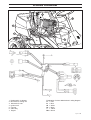
1
Rider 18 ProFlex
Rider 20 ProFlex
Operator´s manual
Please read these instructions carefully and make sure
you understand them before using the machine.
101 89 84-26
Svenska –
Sve-5 225/232/235 Bruk
31
97-11-25, 08.46
31
CONTENTS
Operator’s Manual for
Rider 18 ProFlex and Rider 20 ProFlex
Safety instructions ............................................. 2
Safety rules for USA ........................................ 2
Explanation of symbols ..................................... 4
Safety instructions ............................................. 5
General use ...................................................... 5
Driving on slopes ............................................. 6
Children ............................................................ 7
Maintenance ..................................................... 7
Presentation......................................................... 9
Location of the controls ................................... 9
Throttle control ...............................................10
Choke lever .................................................... 10
Speed limiter .................................................. 10
Cutting unit ..................................................... 11
Lift lever for cutting unit .................................. 11
Lever for adjustment of cutting height ........... 12
Parking brake ................................................. 12
Seat ................................................................ 12
Fuelling ........................................................... 12
Driving ................................................................ 13
Before starting ................................................ 13
Starting the engine ........................................ 13
Driving the machine ....................................... 14
Cutting tips ..................................................... 15
Stopping the engine ...................................... 16
Disengage lever ............................................. 16
Maintenance....................................................... 17
Maintenance schedule .................................. 17
Dismantling of the machine hoods ................ 18
Checking the engine’s oil level ...................... 19
Checking the engine’s cooling air intake ....... 19
Checking the fuel pump’s air filter ................. 19
Checking the transmission’s air intake .......... 20
Checking the transmission’s oil level ............. 20
Checking and adjusting the steering wires .... 21
Adjusting the brakes ...................................... 22
Checking the battery acid level ..................... 22
Checking the safety system .......................... 22
Replacement of air filter ................................ 23
Fitting the cutting unit .................................... 24
Setting the parallelism ................................... 26
Setting the cutting height ............................... 26
Checking and adjusting the ground pressure 27
Service position for the cutting unit ................ 28
Checking the blades ...................................... 28
Dismantling the cutting unit ........................... 29
Dismantling the belts ..................................... 31
Assembling the belts ..................................... 32
Changing the cutting unit’s belts .................... 33
Changing the oil .............................................35
Replacement of the oil filter ........................... 36
Lubrication ...................................................... 36
General lubrication ........................................ 36
Checking and adjustment of throttle wire ...... 37
Checking the tyre pressure ........................... 38
Replacement of fuel filter ............................... 38
Cleaning the pulse air filter ............................ 38
Trouble shooting schedule .............................. 39
Storage ............................................................... 40
Winter storage ................................................40
Service ........................................................... 40
Wiring diagram .................................................. 41
Technical data .................................................... 42
IMPORTANT INFORMATION
Read through these instructions carefully
so that you know how to use and maintain
the machine before using it.
For servicing other than described in this
manual contact an authorised dealer for
parts and service.
English –
1
SAFETY INSTRUCTIONS
!
1. Safety rules for USA
!
Safe operation practices for ride-on mowers
IMPORTANT!
This cutting machine is capable of amputating hands and feet and throwing objects. Failure to observe the following safety instructions could result in serious injury or death.
I.
General operation
1. Read, understand and follow all instructions in
the manual and on the machine before starting.
2. Only allow responsible adults, who are familiar
with the instructions, to operate the machine.
3. Clear the area of objects such as rocks, toys,
wire, etc., which could be picked up and
thrown by the blade.
4. Be sure the area is clear of other people
before mowing. Stop the machine if anyone
enters the area.
5. Never carry passengers.
6. Do not mow in reverse unless absolutely
necessary. Always look down and behind
before and while backing.
7. Be aware of the mower discharge direction
and do not point it at anyone. Do not operate
the mower without either the entire grass
catcher or the guard in place.
8. Slow down before turning.
9. Never leave a running machine unattended.
Always turn off blades, set parking brake, stop
engine and remove keys before dismounting.
10. Turn off blades when not mowing.
11. Stop engine before removing grass catcher or
unclogging chute.
12. Mow only in daylight or good artificial light.
13. Do not operate the machine while under the
influence of alcohol or drugs.
14. Watch for traffic when operating near or
crossing roadways.
15. Use extra care when loading or unloading the
machine into a trailer or truck.
II.
Slope operation
Slopes are a major factor related to loss-of-control
and tip-over accidents, which can result in severe
injury or death. All slopes require extra caution. If
you cannot back up the slope or if you feel uneasy
on it, do not mow it.
DO
Mow up and down slopes, not across.
Remove obstacles such as rocks, tree limbs,
etc.
Watch for holes, ruts or bumps. Uneven terrain
could overturn the machine. Tall grass can
hide obstacles.
2 – English
Use slow speed. Choose a low gear so that
you will not have to stop or shift while on the
slope.
Follow the manufacturer’s recommendations
for wheel weights or counterweights to improve
stability.
Use extra care with grass catchers or other
attachments. These can change the stability of
the machine.
Keep all movement on the slopes slow and
gradual. Do not make sudden changes in
speed or direction.
Avoid starting or stopping on a slope. If tires
lose traction, disengage the blades and proceed slowly straight down the slope.
DO NOT
Do not turn on slopes unless necessary and
then, turn slowly and gradually downhill, if
possible.
Do not mow near drop-offs, ditches or
embandments. The mower could suddenly turn
over if a wheel is over the edge of a cliff or
ditch, or if an edge caves in.
Do not mow on wet grass. Reduced traction
could cause sliding.
Do not try to stabilize the machine by putting
your foot on the ground.
Do not use grass catcher on steep slopes.
III. Children
Tragic accidents can occur if the operator is not
alert to the presence of children. Children are often
attracted to the machine and the mowing activity.
Never assume that children will remain where you
last saw them.
1. Keep children out of the mowing area and
under the watchful care of another responsible
adult.
2. Be alert and turn machine off if children enter
the area.
3. Before and when backing, look behind and
down for small children.
4. Never carry children. They may fall off and be
seriously injured or interfere with safe machine
operation.
5. Never allow children to operate the machine.
6. Use extra care when approaching blind corners, shrubs, trees or other objects that may
obscure vision.
SAFETY INSTRUCTIONS
IV. Service
1. Use extra care in handling gasoline and other
fuels. They are flammable and vapours are
explosive.
a) Use only an approved container.
b) Never remove gas cap or add fuel with the
engine running. Allow engine to cool before
refuelling. Do not smoke.
c) Never refuel the machine indoors.
d) Never store the machine or fuel container
inside where there is an open flame, such as
in a water heater.
Danger, keep hands and feet away
2. Never run a machine inside a closed area.
3. Keep nuts and bolts, especially blade attachment bolts, tight and keep equipment in good
condition.
4. Never tamper with safety devices. Check their
proper operation regularly.
5. Keep machine free of grass, leaves or other
debris build-up. Clean up oil or fuel spillage.
Allow machine to cool before storing.
6. Stop and inspect the equipment if you strike an
object. Repair, if necessary, before restarting.
7. Never make adjustments or repairs with the
engine running.
8. Grass catcher components are subject to wear,
damage and deterioration, which could expose
moving parts or allow objects to be thrown.
Frequently check components and replace with
manufacturer’s recommended parts, when
necessary.
9. Mower blades are sharp and can cut. Wrap the
blade(s) or wear gloves and use extra caution
when servicing them.
10. Check brake operation frequently. Adjust and
service as required.
English –
3
EXPLANATION OF SYMBOLS
These symbols are on the machine and in the instructions.
Study them carefully so that you know what they mean.
Read the instructions.
R N
Reverse
Neutral
Oil pressure
Fast
Slow
Cutting height
Engine off
Battery
Backwards
Choke
Forwards
Fuel
Ignition
!
Use hearing protection
Sound level
Hydrostatic freewheel
Warning! Rotating blades
Never use the machine if persons,
especially children, or animals,
are in the vicinity
Warning! Risk that the
machine can tip over
Never carry passengers on the
machine or equipment
Starting instructions
Read the instructions
Check the engine’s oil level
Check the hydrostat’s oil level
Lift up the cutting unit
Put the gear shift/hydrostat pedal in
neutral
Brake
If the engine is cold use the choke
Start the engine
Release the parking brake before
driving
4 – English
Parking brake
Brake
Never drive across
a slope
Keep hands and feet away
from under the hood when
the engine is running
Warning
European standard for
machine safety
Drive very slowly
without the cutting unit
Speed limiter pedal forwards
Neutral
Speed limiter pedal reverse
Switch off the engine and take off
the ignition cable before repairs or
maintenance
SAFETY INSTRUCTIONS
These instructions are for your safety. Read them carefully.
!
This symbol implies that important safety rules are applicable. This is for your safety
and the operating reliability of the machine.
General use:
•
Make yourself familiar with the controls and how
to stop quickly.
•
Read all the instructions in Operator’s Manual
and on the machine before starting it. Make sure
you understand them, and then follow them.
•
Only allow adults who are familiar with the
machine to use it.
•
Wear approved safety glasses or a visor during
assembly and driving.
•
Never use the machine barefoot. Always wear
heavy-duty shoes, preferably toe-capped.
•
Never wear loose fitting clothes which can
fasten in moving parting.
•
Clear the area of objects such as stones, toys,
and wires, etc. which can be caught up by the
blades and thrown out.
•
Check that there are no other persons in the
area before starting to cut.
•
Stop the machine if anyone comes into the work
area.
•
Never carry passengers.
•
Do not cut backwards unless absolutely necessary.
•
Always look down and behind before and during
reversing.
•
Keep an eye on the ejected grass and do not
direct it towards anyone.
•
Slow down before turning.
•
Never leave the machine unattended when the
engine is running. Always switch off the blades,
pull on the parking brake, stop the engine and
take out the keys before leaving the machine.
•
Switch off the blades when you are not cutting.
•
Only cut in daylight or good artificial lighting.
RIDE
R 97
0
Read the instructions before starting the machine.
Clear the area from stones etc. before cutting.
RIDE
R 85
0
RID
•
ER
850
Never use the machine when you have consumed alcohol, drugs, or certain medicines.
Never carry passengers.
!
WARNING!
This machine can cut off hands and feet, and eject objects. Failure to follow
the safety instructions can lead to severe injury.
English –
5
SAFETY INSTRUCTIONS
•
Watch out for traffic when working close to a
road, or crossing one.
•
Be careful when rounding a fixed object so that
the blades do not hit it. Never drive intentionally
over a foreign object.
•
The machine is heavy and can cause very
severe crush injuries. Be extra careful when
loading it on a trailer or truck.
•
Be careful when pulling a load or using heavy
equipment.
a. Only use approved tow hooks.
b. Limit the load to what you can manage safely.
c. Do not make sharp turns. Be careful when
reversing.
d. Use counterweights or wheel weights when
indicated in the instructions.
Driving on slopes
DE
R8
50
Driving on slopes is one of the situations where
there is the most serious risk that the driver can
loose control or that the machine tips over, which
can cause severe injuries or be fatal. All slopes
require extra care. If you cannot reverse up the
slope or if you feel uncertain avoid cutting it.
RI
Do as follows:
RIDER
•
Remove obstacles such as stones and branches
etc.
•
Cut upwards and downwards, not sideways.
•
Look out for and avoid driving over furrows,
holes or mounds. On uneven surfaces it is
easier for the machine to tip over. High grass
can conceal obstacles.
•
Drive slowly. Select a low gear to avoid having
to stop and changing gear. It is also easier to
use the gear to brake in a low gear.
•
Follow the manufacturer’s recommendations on
wheel weights or counterweights to increase
stability.
•
Be extra careful with the grass collector or other
equipment which can alter the stability of the
machine.
•
Always drive smoothly and slowly on slopes.
Avoid sudden changes of speed or direction.
•
Avoid starting or stopping on a slope. If the tyres
begin to skid switch off the blades and drive
slowly down the slope.
Do not do the following:
•
Avoid unnecessary turns on slopes, and if
turning is necessary turn slowly and gradually,
downwards if possible.
6 – English
850
Be extra careful when driving on slopes.
Cut slopes upwards and downwards, not sideways.
SAFETY INSTRUCTIONS
•
Do not cut close to edges, ditches or banks. The
machine can suddenly tip over if a wheel goes
over the edge of a drop or a ditch, or if a bank
gives way.
•
Do not cut wet grass. It is slippery and the tyres
can loose their grip so that the machine slides.
•
Do not try to stabilise the machine by placing
one foot on the ground.
•
The Rider lawn mower must never be driven
close to an edge or ditch when cleaning the
chassis.
Children
Tragic accidents can occur if the driver does not
pay attention to children in the vicinity. Children are
often attracted to the machine and the work of
mowing. Never assume that children stay where
you last saw them.
•
Keep children away from the mowing area and
under the supervision of another adult.
•
Be on your guard and switch off the machine if
children come into the work area.
•
Before and during reversing look behind and
down for small children.
•
Never allow children to ride on the machine.
They can fall off and become seriously injured or
obstruct an otherwise safe manoeuvre of the
machine.
•
Never allow children to steer the machine.
•
Be extra careful close to corners, bushes, trees
or other objects which obstruct your view.
Keep children away from the mowing area.
RIDE
R 85
0
RID
ER
850
Never allow children to drive the machine.
Maintenance
•
Petrol and petrol fumes are toxic and highly
inflammable. Be extra careful when handling
petrol.
•
Store the fuel in containers approved for this
purpose.
•
Never fill up the machine with petrol when the
engine is running. Let the engine cool before
filling up with petrol. Do not smoke, or fill up with
fuel in the vicinity of naked flames or sparks.
•
Never fill up with fuel indoors.
•
If leakage has occurred in the fuel system the
engine must not be started until this is rectified.
•
Never store the machine or fuel containers
indoors if there are naked flames, such as in a
boiler room or where there is electrical equipment which can emit sparks.
•
RIDE
R 97
0
Never fill up with fuel indoors.
Check the fuel level each time before using the
English –
7
SAFETY INSTRUCTIONS
machine, and leave space for the fuel to expand
since the heat from the engine and hot sun can
cause the fuel to run over.
•
Avoid overfilling. If petrol has been spilt on the
machine wipe it up and wait until it has evaporated before starting the engine. If petrol is spilt
on clothes, change them.
•
Be extra careful when handling battery acid.
Spilling acid on the skin can cause severe burn
injuries. Rinse immediately with water. If acid
gets into the eyes this can cause blindness.
Contact a doctor.
•
Be careful with the maintenance of the battery.
Explosive gas is formed in the battery. Never
handle the battery when smoking or in the
vicinity of naked flames or sparks. Otherwise the
battery can explode and cause severe injuries.
•
Never drive the machine in an enclosed space.
The exhaust fumes contain carbon monoxide,
an odourless, toxic and fatal gas.
•
Make sure that bolts and nuts, especially attachment bolts for the blade units are properly
tightened and that the equipment is in good
order.
•
Never alter the safety devices. Check regularly
that they function. The machine must not be
driven with defective or unmounted safety
devices.
•
Do not alter the setting of the governor and do
not race the engine.
•
Reduce the fire risk. Keep the machine clean
from grass, leaves and other refuse which
fastens in it. Allow the machine to cool before
placing it in the storage area.
•
Stop and inspect the equipment if you drive over
an object. If necessary repair the machine
before starting.
•
Never make adjustments with the engine running.
Never smoke in the vicinity of the battery or the fuel.
058
RED
IR
Never drive the machine in an enclosed space.
RIDE
•
The parts on the grass collector can become
worn, damaged and aged, so that moving parts
are exposed or so that an object can be thrown
out. Check the parts regularly and if necessary
replace them with spare parts recommended by
the manufacturer.
•
The machine is tested for safety and approved
only for equipment supplied or recommended by
the manufacturer.
•
The blades are sharp and can cause cutting
injuries. Wrap over the blades or use protective
gloves when handling them.
•
Check the functioning of the brakes regularly.
Adjust and maintain them as necessary.
8 – English
R 97
0
Clean the machine regularly from grass, leaves and
other waste.
PRESENTATION
Presentation
Congratulations on choosing an excellent quality
product, Rider ProFlex. These instructions describe
two models, Rider 18 ProFlex and Rider 20
ProFlex.
The power transmission from the engine is handled
by a hydrostatic gearbox, which enables variable
speed by using the pedals. One pedal for driving
forward and one for reverse.
Rider ProFlex is equipped with Vanguard V-Twin
engines from Briggs & Stratton in 18 and 20
horsepower designs.
8
7
9
6 5
10
11
4 3 2
1
13
12
13
14
Location of the controls
1. Ignition lock
8. Speed limiter for driving forward
2. Choke lever
9. Brake pedal
3. Throttle control
10. Lock button for parking brake
4. Counter
11. Lever for adjustment of seat
5. Lever for adjustment of cutting height
12. Fuel tank cap
6. Lifting lever for cutting unit with lock button
13. Main lock
7. Speed limiter for reversing
14. Lever to disengage the drive
English –
9
PRESENTATION
Throttle control
The throttle control regulates the engine speed, and
thereby also the rotation speed of the blades.
To increase or reduce the engine speed the control
is moved forwards or backwards.
Choke lever
The choke lever is used for cold starting and to give
the engine a richer fuel mixture.
For cold starting the lever is moved backwards to
its end position.
Speed limiter
The speed of the machine is steplessly regulated
with two pedals. Pedal (1) is used to drive forwards,
and pedal (2) to reverse.
10 – English
1
2
PRESENTATION
Cutting unit
Rider 18 ProFlex and Rider 20 ProFlex can be
equipped with numerous attachments.
Examples of the accessories for Rider:
•
Brush
The BioClip unit finely cuts the lawn by cutting the
grass several times before returning the clippings to
the lawn as fertiliser.
•
Snow plough
•
Wheel weights
The cutting unit with side or rear ejection, that is, the
clippings are ejected to the side or behind the unit.
•
Snow chains
•
Dozer
•
Edger
•
Electric attachment lift
•
BioClip cutting unit
•
Gravel rake
•
Trailer
Lift lever for cutting unit
The lift lever is used to set the cutting unit in
transport or mowing position.
1. Pull back the lever to the locked position for
transport.
The cutting unit will lift up and the blades stop
rotating.
Lifting of the cutting unit
2. Press in the lock button and move the lever
forwards for the mowing position.
The unit will lower down and the blades start to
rotate.
3. The lever can also be used to temporarily
regulate the cutting height, e.g. for a small
mound in the lawn.
Lowering of the cutting unit
English –
11
PRESENTATION
Lever for adjustment of the cutting
height
The cutting height can be adjusted to 7 different
positions with the cutting height lever.
To achieve an even cutting height it is important
that the tyre pressures are the same on the front
wheels (60 kPa).
Parking brake
The parking brake is applied as follows:
1. Push down the brake pedal.
2. Push in the lock button on the steering column.
3. Release the brake pedal while holding the
button pressed.
The parking brake lock disengages automatically
when the brake pedal is pressed.
Seat
The seat has a jointed attachment on the front edge
and can be tipped forward.
The seat can also be adjusted lengthways.
To adjust move the lever under the front edge of the
seat to the left, so that the seat can be moved
forward or backwards to the required position.
Fuelling
The engine should be run on at least 85 octane,
unleaded petrol (not mixed with oil).
!
12 – English
WARNING!
Petrol is highly inflammable. Exercise
care and refuel outdoors (see safety
instructions).
DRIVING
Before starting
•
Read the safety instructions and information on
the location and function of the controls before
starting (see pages 5–12).
•
Conduct daily maintenance before starting (see
maintenance schedule on page 17).
•
Adjust the seat to the required position.
Starting the engine
1. Lift up the cutting unit by pulling the lever backwards to locked position (transport position) and
apply the parking brake.
2. Move the throttle control to the middle position.
3. If the engine is cold move the choke lever
backwards to its end position.
4. Turn the ignition key to the start position.
English –
13
DRIVING
5. When the engine starts release the ignition key
immediately back to neutral position.
IMPORTANT INFORMATION
Do not run the starter for more than about
5 seconds at a time. If the engine does not
start, wait about 10 seconds before trying
again.
6. Push the choke lever gradually forward when
the engine has started.
7. Set the required engine speed with the throttle
control.
!
WARNING!
Never run the engine indoors, in
enclosed or poorly ventilated areas.
The exhaust fumes contain toxic
carbon monoxide.
Driving the machine
1. Release the parking brake by pressing the brake
pedal.
2. Carefully press down one of the pedals until the
required speed is obtained.
To drive forward press down pedal (1), or to
reverse pedal (2).
14 – English
1
2
DRIVING
3. Select the required cutting height (1–7) with the
cutting height lever.
4. Push in the lock button on the lift lever and lower
down the cutting unit.
Cutting tips
!
WARNING!
Clear the lawn from stones and other
objects which can be thrown out by the
blades.
•
Localise and mark stones and other fixed
objects to avoid collision.
•
Start with a high cutting height and reduce down
until the required mowing results are obtained.
•
The mowing results are best with a high engine
speed (fast rotating blades) and low driving
speed (slow moving machine). If the grass is not
too high and thick the driving speed can be
increased or the engine speed reduced without
noticeably affecting the mowing results.
•
The best lawns are achieved if the grass is cut
often. Mowing becomes more uniform and the
grass cuttings become more evenly distributed
over the surface.
The total time consumption is not greater since it
is possible to select a higher driving speed
without inferior mowing results.
•
Avoid mowing a wet lawn. The mowing results
are inferior since the wheels sink down into the
soft lawn.
•
Hose down the cutting unit with water
underneath each time it is used. The cutting unit
should be raised into the service position when
cleaning.
Mowing pattern
English –
15
DRIVING
!
WARNING!
Never drive the machine on ground at an
angle of more than 15°. Mow slopes
upwards and downwards, never across.
Avoid sudden changes in direction.
MAX 15
Stopping the engine
Preferably allow the engine to idle for a minute to
obtain normal working temperature before stopping
it if it has been working hard.
1. Lift up the cutting unit by pulling the lever back
to the locked position.
2. Move the throttle control to the MIN. position.
Turn the ignition key to the STOP.
Disengage lever
To move the machine when the engine is switched
off the disengage lever must be pulled backwards.
16 – English
MAINTENANCE
Maintenance schedule
The following is a list of the maintenance which should be conducted on the machine. For the items which
are not described in these instructions go to an authorised service workshop.
Daily
mainPage
tenance
before start
Maintenance
Check the engine’s oil level
Check the engine’s cooling air inlet
Check the fuel pump’s air filter
Check the transmission’s air inlet
Check the transmission’s oil level
Check the steering wires
Check the battery
Check the safety system
Check screws and nuts
19
19
19
20
20
21
22
22
–
●
●
●
●
●
●
●
●
❍
Check for fuel and oil leakage
–
❍
Clean the air filter’s pre-filter (foam plastic) 2)
Check the cutting unit
Check the tyre pressures (60 kPa)
Adjust the brakes
Check the V-belts
23
27
36
22
–
Change the engine oil 1)
Lubricate joints and shafts 3)
Check and adjust the throttle wire
33
34
35
Replace the air filter’s pre-filter and paper filter 2)
Replace the oil filter
Replace the fuel filter
Clean the pulse-air filter
Replace the plugs
Clean the engine’s and the hydrostat’s cooling flanges 2,4)
23
34
36
38
–
–
Check the valve clearance 4)
Check the valves and seats 4)
–
–
Maintenance interval
in hours
25
50
100
300
●
●
●
●
❍
●
●
●
●
●
●
●
❍
❍
❍
❍
1)
First change after 8 hours. 2) During dusty conditions cleaning and replacement should be more frequent. 3) For daily use of the
machine lubrication should be conducted twice a week. 4) Conducted by authorised service workshop.
● = Described in these instructions.
❍ = Not described in these instructions.
!
WARNING!
No service procedures must be conducted on the engine or cutting unit unless:
•
The engine is switched off.
•
The parking brake is applied.
•
The ignition key is removed.
•
The cutting unit is disengaged.
•
The ignition cables are removed from the plugs.
English –
17
MAINTENANCE
Dismantling of the machine hoods
Engine hood
Release the two rubber straps on the rear edge of
the engine hood and lift off the hood.
Nose
Loosen the quick-action lock and lift off the nose.
Right-hand fender
Dismantle the foot-plate (1), screws (2 and 3), and
lift off the fender.
2
1
3
Left-hand fender
Dismantle the screws (1 and 2), and lift off the
fender.
1
2
18 – English
MAINTENANCE
Check the engine’s oil level
Check the oil level in the engine when the machine
is horizontal.
Dismantle the engine hood as per the description
on page 18.
Take out the dip stick, wipe off the oil, and insert
again.
The dip stick must be fully screwed down.
Now take out the dip stick again and check the oil
level.
The oil level should lie between the markings on dip
stick. If the level approaches the ADD mark, top up
with oil to the FULL mark on the dip stick.
ADD
The oil is filled in the same hole as the dip stick is in.
FULL
Use engine oil SAE 30 or SAE 10W-30, class CD–CF
(over 0°). Use engine oil SAE 5W-30, class CD–CF
(below 0°).
The total oil volume in the engine is 1.4 litres.
ADD
FULL
Check the engine’s cooling air intake
Dismantle the engine hood as described on page 18.
Check that the cooling intake is free from leaves,
grass and dirt.
If the cooling intake is blocked this will interfere with
the cooling of the engine, which can damage the
engine.
Checking of the fuel pump’s air filter
Check regularly that the fuel pump’s air filter is free
from dirt.
The filter can when necessary be cleaned with a
brush.
English –
19
MAINTENANCE
Check the transmission’s air intake
Check that the transmission’s air intake in not
blocked.
Check the transmission’s oil level
1. Check the transmission’s oil level by looking
through the mesh on the air intake. The oil level
should lie between the MIN and MAX markings
on the oil canister at 20° C.
If oil needs to be added the transmission cover
must be dismantled first. Release the two
screws (one on each side) and then lift off the
transmission cover.
2. Screw off the oil canister cap and top up with
engine oil SAE 10W/30, class CD–CF, until the
oil level reaches the MAX marking. Screw the oil
canister cap back on, and fit the transmission
cover.
20 – English
MAINTENANCE
Checking and adjustment of the
steering wires
The steering is controlled by means of wires.
These can in time become slack, which implies that
the adjustment of the steering becomes altered.
Check and adjust the steering as follows:
1. Dismantle the frame-plate by releasing the
screws (two on each side).
2. Check the tension of the steering wires by
pushing them together (at the arrows).
It should be possible to push them together so
that the distance between them is half as much,
without using unnecessary force.
3. When necessary the wires can be tensioned by
tightening the adjusting nuts (one on each side
of the machine).
Do not tension the wires too tightly, they should
only be tightened up to the steering rim.
Check the wire tension on completion of the
adjustment as per item 2.
English –
21
MAINTENANCE
Adjusting the brakes
The brakes are adjusted as follows:
1. Loosen the lock nuts (A).
2. Adjust the wire using the adjuster screw (B)
until the play on the wire is taken up.
3. Tighten the lock nuts (A).
!
WARNING!
Poorly adjusted brakes can
result in reduced braking power.
Check the level of the battery acid
Check that the level of the battery acid lies between
the markings. Top up the cells with distilled water only.
!
WARNING!
Procedures on contact with acid
External: Rinse well with plenty of water.
Internal: Drink large quantities of water or
milk. Contact a doctor as soon as
possible.
Eyes:
Rinse well with plenty of water.
Contact a doctor as soon as possible.
Batteries emit explosive gas. Sparks, flames
and cigarettes must absolutely not be
brought into the vicinity of the battery.
Check the safety system
The machine is equipped with a safety system
which prevents starting or driving the machine
unless someone is sitting in the seat. Check daily
that the safety system functions.
22 – English
B
A
A
MAINTENANCE
Replacing the air filter
If the engine seems to lack power or does not run
smoothly this may be because the air filter is
clogged.
It is therefore important to replace the air filter at
regular intervals (see maintenance schedule on
page 17 for correct service interval).
The air filter is replaced as follows:
1. Dismantle the engine hood as described on
page 18.
2. Fold out the two snap-locks and lift off the cover
on the air filter housing.
3. Release and remove the wing-nut in the centre
of the air filter and lift off the paper filter with prefilter.
4. Pull off the foam plastic pre-filter from the paper
filter and wash clean in mild detergent.
Squeeze it dry in a clean cloth.
Drench it with new engine oil. Wrap the filter in
an absorbent cloth and squeeze out excess oil.
If the paper filter is heavily soiled it should be
replaced.
IMPORTANT INFORMATION
Do not use compressed air to clean the
paper filter.
5. Fit the air filter as follows:
Push the pre-filter over the paper filter.
Fit the paper filter with pre-filter in the air filter
housing and tighten the wing-nut in the centre.
Replace the cover over the air filter housing and
clamp the two snap-locks tight.
English –
23
MAINTENANCE
The parts of the cutting unit
A cutting unit with a rear ejector has been used in
the instructions below, however, the same procedure
applies to other units if not otherwise stated.
The parts mentioned are:
A. Catch
E. Height setting arm
B. Inner pin
F. Parallelism arm
C. Hook guard
G. Lowest height setting stop
D
F
C
B
D. Handle
A
E
G
Fitting the cutting unit
Starting point for fitting the unit:
•
Place the Rider on a level surface.
•
Apply the brakes by pressing down the pedal
and lock using the pushbutton.
•
The attachment frame in the lowered position.
•
The attachment frame locked with the hook
guard and the catch (A) in the loaded position.
A
1. Fit the unit in the attachment frame’s outer
hooks.
2. Pull out the catch (A) and release the hook
guard by sliding its handle backwards.
3. Lift the attachment by pulling up the lever
located on the driver’s right-hand side.
A
24 – English
MAINTENANCE
4. Slide in the unit so that the inner pins (B) bottom
in the attachment frame’s groove.
B
5. Fit the height setting arm’s rear bracket when
fitting the attachment. Off-load the arm by
pulling the front of the frame upwards.
6. Remove the belt adjuster’s spring and fit the belt
on the front belt pulley.
7. Hook on the belt adjuster’s spring again.
Note!
Check that the belt is fitted around the
tension roller.
Belt diagram
3
4
1. Drive belt
2. Drive pulley
3. Tension roller
1
4. Spring
2
English –
25
MAINTENANCE
Setting the parallelism and height for the cutting unit with rear ejector and
BioClip unit
The base unit is adjusted at the factory. When one
of the attachments is fitted, the parallelism and
height need to be adjusted.
Starting point:
1. The cutting unit should be lowered on a level
surface.
2. The height setting lever should be set for the
lowest cutting height.
Parallelism
Always start by adjusting the parallelism.
1. Loosen the two nuts on the arm.
2. Measure the distance between the ground and
the front edge of the unit, at the front and rear of
the hood.
3. Place a wrench on the bevelled section in the
centre of the arm and turn so that the rear edge
of the cutting unit sits 2-4 mm higher than the
front edge of the unit.
4. Check the measurements.
5. Now tighten the two nuts on the arm.
Cutting height
1. Loosen the nuts on the height setting arm.
2. Adjust so that the distance between the stop for
the lowest height setting and the protective
frame is 5 mm.
3. Tighten the nuts.
4. Check that the parallelism has not changed. If it
has changed, the parallelism must be
readjusted again.
5. Check and adjust the cutting unit’s ground
pressure as set out on page 25, if necessary.
6. Fit the nose.
NOTE!
The parallelism and height must be adjusted
again when changing the cutting unit.
26 – English
5 mm
MAINTENANCE
Checking and adjustment of the cutting
unit’s ground pressure
To achieve the best cutting results the cutting unit
should follow the underlying surface without pressing too hard against it.
The pressure is adjusted with a screw on each side
of the machine.
Adjusting of the cutting unit’s ground pressure is
conducted as follows:
1. Place a set of bathroom scales under the cutting
unit’s frame (front edge) so that it rests on the
scales. If necessary a block can be placed
between the frame and scales so that the support wheels do not bear any weight.
2. Adjust the unit’s ground pressure by screwing in
or out the adjusting screws located behind the
front wheels on both sides.
The ground pressure should be between 12 and
15 kg.
English –
27
MAINTENANCE
Service position for the cutting unit
The cutting unit can be set in a service position to
provide good access for cleaning, servicing and
repair. The service position means that the unit is
raised and locked in the vertical position.
Placing in the service position
1. Position the unit so it hangs over the outer
hooks by carrying out sections 1–11 under
“Dismantling the unit”.
2. Take hold of the front edge of the unit and lift it
vertically. The unit is automatically locked in the
vertical position.
Releasing from the service position
1. Loosen the top edge of the unit (move it
backwards), move the handle forwards and
slowly lower the unit to its horizontal position.
2. Slide the unit into its working position by
carrying out sections 4–8 under “Assembling
the unit”.
Checking the blades
To achieve the best mowing results it is important
that the blades are undamaged and wellsharpened.
Check that the blades’ attachment screws are tight,
(45–60 Nm, 33–44 lb.ft)
The spring washer and break-pin should also be
replaced when replacing the blades.
IMPORTANT INFORMATION
Cutting unit with rear ejector
Replacing or sharpening the blades
should be conducted by an authorised
service workshop.
IMPORTANT INFORMATION
The Bioclip unit should always have the
blades in the relative positions shown in
the diagram, with a 90° angle between the
blades. Otherwise the blades can go
against each other and cause serious
damage to the unit.
BioClip unit
28 – English
MAINTENANCE
Dismantling the cutting unit
1. Place the Rider on a level surface.
2. Apply the brakes by pressing down the pedal
and lock using the pushbutton.
3. Lift up the unit using the lifting lever.
4. Remove the nose.
5. Remove the belt adjuster’s spring.
6. Lift off the belt from the belt pulley.
7. Hook on the belt adjuster’s spring again.
8. Hang the belt around the handle.
English –
29
MAINTENANCE
9. Loosen the height setting arm by moving the
rear section upwards. When dismantling the
cutting unit, off-load the arm by pulling the
frame’s front section upwards.
10. Pull the handle and unit simultaneously. Release
the handle when the unit has come out a little.
11. Pull out the unit so that it engages in the outer
hooks.
12. Lower the unit using the lever on the right-hand
side of the driver.
13. Pull the handle so that the hook guard locks.
Check that the catch (A) is in its loaded position.
14. Lift the unit off of the Rider.
A
30 – English
MAINTENANCE
Dismantling the belt
Starting point when dismantling the belt:
•
No unit attached to the Rider.
•
The front of the belt is hung around the hook
guard’s handle.
How the front of the belt is removed from the front
belt pulley is evident from sections 5–8, on page 27.
The entire belt is only dismantled as set out below,
when the snow plough is fitted on the Rider.
1. Dismantle the steering plate under the support
wheel. Use two 13 mm socket spanners.
2. Unhook the spring on the blade brake.
3. Pry off the belt from the intermediate pulley and
remove the belt.
English –
31
MAINTENANCE
Assembling the belt
1. Position the belt from the front and let the front
end of the belt hang around the hook guard’s
handle.
2. Fit the belt on the intermediate pulley and
against the support wheel.
3. Fit the steering plate under the support wheel
and tighten the bolts using two 13 mm socket
spanners.
4. Hook on the spring for the blade brake.
How the belt is fitted on the front belt pulley is
evident from sections 6–7, on page 23.
32 – English
MAINTENANCE
Replacing the cutting unit’s belts
Belt replacement on the BioClip unit
Two transmission belts that synchronise the rotation of the blades power a BioClip unit. The belts
are located under a hood on the cutting unit.
1. Loosen the parallelism arm’s front pin/bolt and
fold the arm backwards.
2. Loosen the two bolts holding the protective
hood and then lift off the hood.
3. Loosen the nuts on the eccentric plate and turn
this away.
Loosen the four nuts (see diagram) holding the
outer blade bearing enough so that the bearing
can be moved.
Slide the blade bearing in towards the centre
bearing and pry off the upper belt.
Repeat the procedure for the lower belt.
!
WARNING!
Protect your hands by wearing gloves
when working with the blades.
English –
33
MAINTENANCE
IMPORTANT INFORMATION
The blades on a BioClip deck should be set
at 90 degrees to each other. In all other
cases the blades can collide and cause
serious damage to the cutting unit.
4. Assembly: First fit the lower belt and then the
upper belt.
90
90
Ensure the blades are positioned as set out in
the diagram, at 90 degrees to each other,
otherwise the belts must be adjusted. When the
blade bearings are loose the belts can be
moved around to the next tooth.
Tighten the nuts enough so that the bearings
rest against the cutting hood but still can be
moved.
Tension the belt by turning the eccentric adjuster
on top of the cutting hood. Tighten the nut.
7 mm
Tighten all nuts on the blade bearings.
5. When the belt can be moved 7 mm inwards using
a force of 10 N the belt is adjusted correctly.
10 N
Fit the protective cover over the belts and
replace the parallelism arm.
Belt replacement on cutting unit’s with side or
rear ejectors
3
Cutting units with side or rear ejectors are powered
by one V-belt. Proceed as follows to replace the
V-belt:
1. Loosen the unit frame (1), the bolt on the
parallelism arm (2) and the two bolts on the
hood (3). Lift off the cutting unit’s hood.
3
1
2
2. Loosen the spring that tensions the V-belt and
pry off the belt.
To fit a new belt, follow the instructions above in
the reverse order.
34 – English
MAINTENANCE
Changing the oil
The oil should be changed for the first time after 8
hours of running time. Thereafter it should be
changed every 50 hours of running time. If the
engine is run hard or during high temperatures the
oil should be changed every 25 running hours.
!
WARNING!
Engine oil can be very hot if it is
drained off directly after the engine
is stopped. Therefore allow the
engine to cool down first.
1. Dismantle the engine hood as described on
page 18.
2. Place a receptacle under the engine’s drain
plug.
3. Remove the dip stick. Remove the drain plug on
the left-hand side of the engine.
4. Let the oil run out into the receptacle.
5. Fit the oil plug and tighten well.
6. Fill up with oil to the FULL mark on the dip stick.
Use engine oil SAE 30 or SAE 10W-30, class
CD–CF (over 0°). Use engine oil SAE 5W-30,
class CD–CF (below 0°). The total oil volume in
the engine is 1.3 litres.
ADD
FULL
7. Run the engine warm and then check that there
is no leakage from the oil plug.
ADD
FULL
The oil is filled in the same hole as the dip stick.
IMPORTANT INFORMATION
Used engine oil is hazardous to health
and must by law not be poured out on the
ground or in the nature, but shall be
handed in to a workshop or special
environmental station. Avoid skin contact,
wash with soap and water in the event of
spillage.
English –
35
MAINTENANCE
Replacement of the oil filter
1. Dismantle the engine hood as described on
page 18.
2. Drain off the engine oil according to the work
description “Changing of engine oil” on page 27.
3. Dismantle the oil filter. If necessary use a filter
extractor.
4. Apply new, clean engine oil on the seal for the
new filter.
5. Fit the filter and tighten by hand.
6. Run the engine warm and check that there is no
leakage round the oil filter seal.
Lubrication
The following three lubrication points shall be
lubricated regularly with graphite grease of good
quality.
In the event of daily use lubrication should be
conducted twice a week.
General lubrication
All joints and bearings are lubricated on
manufacture with molybdenum sulphide grease.
Re-grease with same type of grease.
Lubricate the steering and control wires with engine
oil.
Conduct this lubrication regularly: during daily use
of the machine it should be lubricated twice a week.
36 – English
MAINTENANCE
Checking and adjustment of the throttle
wire
Check that the engine responds to the throttle
control and that the correct engine speed is
achieved at full throttle.
If in doubt, contact the service workshop
If necessary the following adjustment can be made:
1. Release the clamping screw and push the
throttle control to full throttle position.
2. Pull the throttle wire’s outer casing to the right
and tighten the clamping screw.
English –
37
MAINTENANCE
Checking the tyre pressure
The tyre pressure should be 60 kPa (0.6 kp/cm2)
all round.
To improve driving the pressure on the rear tyres
can be reduced to 40 kPa (0.4 kp/cm2).
The maximum tyre pressure is 100 kPa (1.0 kp/cm2).
IMPORTANT INFORMATION
Different tyre pressures on the front tyres
will result in the blades cutting the grass
at different heights.
Replacement of the fuel filter
Replace the fuel filter every 100 running hours
(once per season) or more frequently if it is
clogged.
Replace the filter as follows:
1. Dismantle the engine hood as described on
page 18.
2. Move the hose clips away from the filter. Use a
pair of flat pliers.
3. Pull off the filter from the hose ends.
4. Press in the new filter on the hose ends. If
necessary soap solution can be applied on the
filter ends to simplify fitting.
5. Push the hose clips back on the filter and
tighten.
Cleaning the pulse air filter
1. Loosen the two rubber straps and lift off the
engine hood.
2. Loosen the four quick-action clips and lift off the
cover and remove the filter.
3. Blow out the filter using compressed air.
4. Replace the filter in the cover and secure the
cover using the quick-action clips. Replace the
engine hood.
38 – English
TROUBLE SHOOTING SCHEDULE
Problem
Procedure
Engine will not start.
•
•
•
•
Fuel tank empty.
Plugs defective.
Plug connections defective.
Dirt in carburettor or fuel pipe.
Starter does not pull round engine.
•
•
•
•
•
•
Battery flat.
Bad contact between cables and battery terminals.
Lift lever for cutting unit in wrong position.
Main fuse blown. The fuse is located in front of the
battery under the battery cover.
Ignition lock faulty.
Gear shift/hydrostat pedal not in neutral.
Engine does not run smoothly.
•
•
•
•
•
•
Plugs defective.
Carburettor incorrectly set.
Air filter clogged.
Fuel tank vent blocked.
Ignition setting defective.
Dirt in fuel pipe.
Engine seems to have no power.
•
•
•
•
Air filter clogged.
Plug defective.
Dirt in carburettor or fuel pipe.
Carburettor incorrectly set.
Engine overheats.
•
•
•
•
•
•
Engine overloaded.
Air intake or cooling flanges blocked.
Fan damaged.
Too little or no oil in engine.
Ignition defective.
Plugs defective.
Battery does not charge.
•
•
One or more cells in the battery faulty.
Bad contact between battery terminals and cables.
Machine vibrates.
•
•
•
Blades are loose.
Engine is loose.
Imbalance on one or more blades, resulting from
damage or inferior balancing after sharpening.
Uneven mowing.
•
•
•
•
•
•
•
Blades blunt.
Cutting unit set skew.
Long or wet grass.
Grass blockage under hood.
Different tyre pressures on right and left sides.
Over-speeding
Drive belts slipping.
English –
39
STORAGE
Winter storage
At the end of the season the machine should
immediately be put in order for storage, also if it is
going to stand idle for more than 30 days. Fuel
which is left to stand for long periods (30 days or
more) can leave tacky deposits which can block the
carburettor and interfere with the engine.
Fuel stabiliser is an acceptable alternative to avoid
tacky deposits during storage. If alkylate petrol
(Aspen) is used stabiliser is not necessary since
this fuel is stable. However, one should avoid
changing from standard to alkylate petrol since
sensitive rubber parts can harden. Add stabiliser to
the fuel in the tank or the storage container. Always
use the mixing ratios indicated by the manufacturer.
Run the engine for at least 10 minutes after adding
the stabiliser so that it will reach the carburettor. Do
not empty the fuel tank and carburettor if stabiliser
has been added.
!
40 – English
WARNING!
Never place an engine with fuel in
the tank indoors or in poorly
ventilated areas where petrol fumes
can come into contact with naked
flames, sparks or pilot flames in
boilers, hot water heaters, or drying
cabinets, etc. It is highly inflammable
and negligent usage can cause
severe person injury and material
damage. Drain off the fuel in an
approved container outdoors and
well clear of naked flames. Never use
petrol for cleaning purposes. Use
degreasing agents and hot water
instead.
To put the machine in order for storage follow these
instructions:
1. Carefully clean the machine, especially under
the cutting unit. Touch-up paint damage to avoid
rust.
2. Inspect the machine for worn or damaged parts
and tighten loose screws and nuts.
3. Change the oil, and take care of the waste oil.
4. Empty the fuel tank. Start the engine and run it
until the carburettor is emptied of fuel.
5. Remove the plugs and pour in a tablespoon of
engine oil in each cylinder. Pull round the engine
to distribute the oil and screw the plugs back on.
6. Grease all grease nipples, joints and axles.
7. Remove the battery. Clean it, charge it, and
store it in a cool place. Protect the battery from
low temperatures (below freezing point).
8. Store the machine in a clean and dry place and
cover it over for extra protection.
Service
When ordering spare parts state the purchase year,
model, type, and serial number.
Always use genuine parts.
Annual inspection or trimming by an authorised
service workshop is a good way of getting the best
out of your machine the next season.
WIRING DIAGRAM
3
5
7
6
4
1
2
1.
2.
3.
4.
5.
6.
7.
Brake switch, hydrostat
Microswitch, cutting unit
Microswitch, seat
Ignition lock
Counter
Start relay
Engine
Explanation of colour abbreviations in wiring diagram.
R = Red
B = Blue
W = White
BL = Black
Y = Yellow
BR = Brown
English –
41
TECHNICAL DATA
Rider ProFlex
Dimensions
Rider 18 ProFlex
Rider 20 ProFlex
Length without unit
Width without unit
Height
Unladen weight
Wheel base
Track
Tyre size
Tyre pressure, front & rear
Max. gradient
2 300 mm
1 280 mm
1 085 mm
300 kg
855 mm
710 mm
18 x 7.50 x 8
60 kPa (0,6 kp/cm2)
15°
2 300 mm
1 280 mm
1 085 mm
350 kg
855 mm
710 mm
18 x 7.50 x 8
60 kPa (0,6 kp/cm2)
15°
Briggs & Stratton
Vanguard V-Twin model 350777,
type 1123, trim A1
13.7/18 kW/hk
570 cm3
min 85 octane unleaded
10 litres
SAE 30 or SAE 10W/30,
class CD - CF
1,4 litres
1,6 litres
Electric starter
Briggs & Stratton
Vanguard V-Twin model 351777,
type 1130, trim E1
14.7/20 kW/hk
570 cm3
min 85 octane unleaded
10 litres
SAE 30 or SAE 10W/30,
class CD - CF
1,4 litres
1,6 litres
Electric starter
12 V, negative earthed
12 V, 24 Ah
Champion RC12YC,
electrode gap = 0.7-0.8 mm
12 V, negative earthed
12 V, 24 Ah
Champion RC12YC,
electrode gap = 0.7-0.8 mm
Tuff Torq K 61
SAE 10W/30, class CD - CF
Tuff Torq K 61
SAE 10W/30, class CD - CF
Engine
Manufacture
Power
Displacement
Fuel
Tank volume
Oil
Oljevolym
Oil volume incl. filter
Start
Electrical system
Type
Battery
Spark plug
Transmission
Manufacture
Oil
When the service life of this product has been served and it is no longer used it should be returned to
the dealer or to an applicable station for recycling.
42 – English
TECHNICAL DATA
Cutting unit
Cutting width
Cutting heights
Blade length
Sound level
Cutting width
Cutting heights
Blade length
Sound level
Rear ejector 120
BioClip 103
1200 mm
7 settings, 40-100 mm
440 mm
100 dB(A)
1030 mm
7 settings, 45-105 mm
410 mm
100 dB(A)
Side ejector 97
Rear ejector 97
970 mm
7 settings, 40-80 mm
350 mm
100 dB(A)
970 mm
7 settings, 40-100 mm
350 mm
100 dB(A)
We reserve the right to change technical specifications without prior notice.
Note that no legal claims are valid on the basis of information in this manual.
Use only genuine parts for repairs. The warranty is not valid if non genuine parts are used.
EU declaration of conformity (Only applies to Europe)
(Directive 89/392/EEC, Annex II, A)
We, Husqvarna AB, S-561 82 Huskvarna, Sweden, tel. +46 36-146500, declare under sole responsibility that
the rider mowers Husqvarna Rider 18 ProFlex and Rider 20 ProFlex from 1998’s serial numbers and
onwards (the year is clearly stated in plain text on the type plate with subsequent serial number), is in conformity
with the following standards or other normative documents following the provisions in the COUNCIL’S
DIRECTIVES:
- of June 14 1989 “relating to machinery” 89/392/EEC, and applicable supplements.
- of March 22 1984 “relating to permitted sound power levels for lawn mowers” 84/538/EEC, and applicable
supplements.
- of May 3 1989 “relating to electromagnetic compatibility” 89/336/EEC, and applicable supplements.
The following standards have been applied: EN292-2, EN836.
Huskvarna October 16, 1998
Bo Andréasson, Development manager
English –
43
NOTES
44 – English
´*2§J¶6)¨
English –
45
´*2§J¶6)¨
1998W51