1
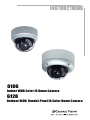
6106
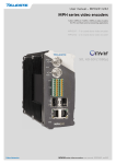
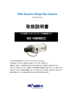
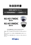
Indoor WDR Color IR Dome Camera
6128
Outdoor WDR Vandal-Proof IR Color Dome Camera
11
Contents
1. SAFETY PRECAUTIONS.................................................................................. 2
2. INTRODUCTION............................................................................................... 3
3. FEATURES ......................................................................................................... 4
4. PACKING LIST.................................................................................................. 5
5. NAME and FUNCTION of EACH PART ..........................................................6
5.1 OSD Button (Menu): ...............................................................................6
6. INSTALLATION.................................................................................................7
6.1 Camera Installation & Operation.............................................................7
6.2 Connect to Monitor................................................................................ 10
6.3 Connect the Power................................................................................. 11
6.4 Connection Layout ................................................................................ 12
6.4.1 Connecting the Keyboard ................................................................... 13
PELCO Keyboard (or compatible) Installation........................................... 13
6.4.2 Connecting the Alarm......................................................................... 14
7. OPERATION..................................................................................................... 15
7.1 PELCO Keyboard (or compatible) Operation....................................... 15
8. SYSTEM SETUP.............................................................................................. 16
8.1 Digital Zoom Operation: ....................................................................... 16
8.2 OSD (On Screen Display) ..................................................................... 16
8.3 Sub Menu Description........................................................................... 17
8.3.1 LENS TYPE ....................................................................................... 17
8.3.2 EXPOSURE Setup ............................................................................. 17
8.3.4 WHITE BALANCE Setup .................................................................19
8.3.5 PRIVACY MASK Setup.................................................................... 20
8.3.6 EFFECT Setup: ..................................................................................21
8.3.7 NOISE REDUCTION Setup .............................................................. 23
8.3.8 MOTION DETECT Setup.................................................................. 23
8.3.9 COMMUNICATION Setup ............................................................... 24
8.3.10 DEFAULT Setup.............................................................................. 25
8.3.11 EXIT Setup....................................................................................... 25
9. SPECIFICATION .............................................................................................. 26
1
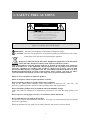
1. SAFETY PRECAUTIONS
CAUTION
RISK OF ELECTRIC SHOCK.
DO NOT OPEN!
C AUTIO N :
TO REDUCE THE RISK OF ELECTRICAL SHOCK,
DO NOT OPEN COVERS (OR BACK).
NO USER SERVICEABLE PARTS INSIDE.
REFER SERVICING TO QUALIFIED
SERVICE PERSONNEL.
It is advised to read the Safety Precaution Guide through carefully before operating the
product, to prevent any possible danger.
WARNING: Alert the user to the presence of un-insulated ? dangerous voltage? .
CAUTION: Alert the user the presence of important operating and maintenance (Servicing)
instructions in the literature accompanying the appliance.
Disposal of Old Electrical & Electronic Equipment (Applicable in the European
Union and other European countries with separate collection systems).
This symbol indicates that this product shall not be treated as household waste. Instead it
shall be handed over to the applicable collection point for the recycling of electrical and
electronic equipment. By ensuring this product is disposed of correctly, you will help
prevent potential negative consequences for the environment and human health. For more
detailed information about recycling of this product, please contact your local city office,
your household waste disposal service or the shop where you purchased the product.
Please be extra careful not to shake the product.
Please avoid places where frequent vibrations or shocks.
Do not install the product in extreme temperature conditions.
Only use the camera under conditions where temperatures are between -10? and +50? . Be
especially careful to provide ventilation when operating under high temperatures.
Do not install the product in an environment where the humidity is high.
Unless the product is waterproof or weatherproof, otherwise it can cause the image quality to be
poor.
Do not expose to strong light (sun rays), as color filters will be discolored.
Do not spill liquid of any kind on the product.
If it gets wet, wipe it dry immediately. Alcohol or beverage can contain minerals that corrode the
electronic components.
When any abnormal occurs, make sure to unplug the unit, and contact your local dealer.
2
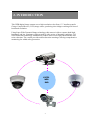
2. INTRODUCTION
This WDR digital image camera uses a high resolution color Sony 1/3” interline transfer
Charge Coupled Device (CCD) image sensor, producing clear images reaching 650 lines of
horizontal resolution.
Using Super Wide Dynamic Range technology, this camera is able to capture both highluminance and low luminance subjects under a wide variety of shooting conditions. 3-D
Noise Reduction technology automatically reduces noise in low light environments after
noise reduction. The camera provides motion detection warnings, offering comprehensive
monitoring for added safety protection.
650TVL
WDR
DNR
3
3. FEATURES
Excellent Sensitivity
High sensitivity, low smear, high antiblooming and high S/N ratio.
High Resolution
CCD Sensor provides high resolutions
reaching 650 TV lines with crisp, clear
picture quality.
Wide Dynamic Range (WDR)
High-quality WDR functionality,
perfectly shows the image details
between dark and light. The newly added
environment dynamic detection switch
enhances WDR image efficiency.
Day & Night
IR cut-filter with AE automatically
changes from color to B&W mode for
day and night 24-hour surveillance.
Selectable between manual Day &
Night control or from external input
signal Day & Night control.
Privacy Mask
Privacy image masking with free
position, supports up to 15 areas of
privacy masking zones. Privacy area
enlarges with the digital zoom-in
function.
Digital Noise Reduction (DNR)
2D/ 3D DNR, captures clear images in
low light environments, saving DVR
hard disk storage space when using
MPEG/MPEG4/H.264 compression.
Digital Slow Shutter (DSS)
When in low light, reduces the image
frame refresh rate and increases the
sensitivity of the camera.
Motion Detection
Provides a motion detection alert for
more comprehensive monitoring and
specific editing of the motion detection
area. When there are changes within
the detection area, the camera
immediately issues a warning.
Extra Connection
Control the camera easily with the
5050 RS-485 interface; Connect the
extra alarm out to combine with the
motion detection function.
Lens (C/CS Mount)
Built-in DC-type Vari-Focal lens with
ICR.
Image Control
Performance: 16x digital zoom, freeze
image, positive/ negative image, mirror
function (left/ right), reverse turn (up/
down), and 180° rotation.
OSD
OSD (On Screen Display) Setup Menu.
Camera tile setup of up to 16
alphanumeric characters
Application
All functions can be operated from OSD: AES (Automatic Electronic Shutter), AI (Auto Iris),
GC (Gain Control), WB (White Balance), BLC (Back Light compensation), and provides the
flickerless mode, and line-lock function.
4
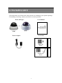
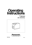
4. PACKING LIST
Check and make sure all the items shown below are included in your product package.
If something is missing, contact your dealer as soon as possible.
Dome (IR Type)
User Manual
or
6106
6128
Accessories
Power Adaptor
Indoor IR
Dome
Outdoor IR
Dome
5
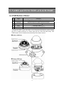
5. NAME and FUNCTION of EACH PART
5.1 OSD Button (Menu):
No.
1
2
3
4
5
Name
Function
UP
DOWN
RIGHT
LEFT
ENTER
Digital Zoom-Out or Up direction button
Digital Zoom-In or Down direction button
Increase Value ( + )
Decrease Value ( - )
Enter or Exit setup MENU
To adjust the OSD, remove the dome cover from the main body by gently turning
the cover counter-clockwise to unlock and pull free from the main body. The
OSD buttons can be found on the main body of the dome camera.
6
6. INSTALLATION
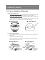
6.1 Camera Installation & Operation
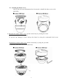
1. Removing the Dome Cover
Remove the indoor dome cover from the main body by gently turning the
cover counter-clockwise to unlock and pull free from the main body.
Remove the outdoor dome cover using the provided L-Wrench, loosen the
screws securing the temper-resistant housing cover (with the screws still
attached on the cover) to unlock the cover from the main body.
2. Camera Image Adjustment
You can adjust camera to any direction by using Pan, Tilt, and Rotate the
mechanism.
Pan Base moves by 360° on the whole.
Tilt Base covers total 119° angle (64° to one side and 55° to the other side).
Angle range of Rotate Base is 360°.
7
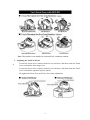
Note: This product is not suitable for horizontal 360° continuous rotation.
3. Adjusting the Vari-Focal Lens
Loosen the Zoom lever counter-clockwise several turns, and then rotate the Zoom
z
lever to obtain the best image view.
Loosen the Focus lever counter-clockwise several turns, and then rotate the Focus
lever to obtain the optimum picture quality.
Re-tighten the Zoom lever and Focus lever after adjustment.
8
4. Attaching the Dome Cover
After all the necessary adjustments have been made, reinstall the dome cover to the
main body.
z
Reinstall the indoor dome cover and the main body by turning the dome
clockwise until it locks into place
To prevent any damage or theft, lock-up the dome by using the countersunk head screw.
Reinstall the outdoor dome cover and the main body by using the provided
L-Wrench to fasten the cover to the main body.
9
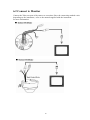
6.2 Connect to Monitor
Connect the Video-out port of the camera to a monitor. Since the connecting method varies
depending on the instrument, refer to the manual supplied with the instrument
for more information.
10
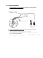
6.3 Connect the Power
Connect the indoor dome video output to a 75 Ohms type coaxial cable and
the DC-Jack or AC/ DC-Terminator to the power source.
z
Connect the outdoor dome video output to a 75 Ohms type coaxial cable
and the DC-Jack or AC/ DC-Terminato r to the power source.
When using conduit cabling, it is suggested to use a metal to cover over the
cables to prevent external damage.
To weatherproof, place weatherproof adhesive tape (P.T.F.E. THREAD SEAL TAPE)
onto the metal cover before installation.
11
Note: Power adapter is sold separately.
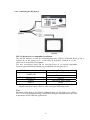
6.4 Connection Layout
To connect the keyboard and alarm, please follow the setup guide shown below:
12
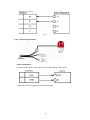
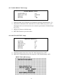
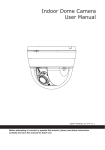
6.4.1 Connecting the Keyboard
PELCO Keyboard (or compatible) Installation
The RS-422 interface is used for communicating with a PELCO keyboard. Refer to Fig. 1;
connect R+ of the camera to T+ of the PELCO keyboard. Connect R- of the
camera to T- of the PELCO keyboard.
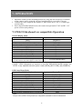
The user can adjust Camera ID via rear panel keys or via remote commands.
Protocol, Speed and Parity should only be adjusted via rear panel keys.
Communication
Setting
0 ~ 253 for P protocol
CAMERA ID
1 ~ 255 for D protocol
PROTOCOL
PELCO
SPEED
2400, 4800, 9600, 19200
PARITY
NONE
The speed of camera should be the same as the speed of the keyboard.
Adjusted function is only effective, after exiting the OSD setup menu.
Note:
Maximum cable distance for RS-485 coMmunication over 24-gauge wire is 4,000
feet (1,219 m). Recommend using a shielded twisted pair cable that meets the basic
requirements for EIA RS-485 applications.
13
Fig.1
6.4.2 Connecting the Alarm
Alarm Installation
Connect GND and AL of the camera to the GND and AL of the alarm.
Note: The alarm is triggered by motion detection.
14
7. OPERATION
1. Mount the camera on the mounting bracket by using the hole on the top or bottom
of the camera, and by using the enclosed mounting block, secured by 2 screws.
2. Connect the video output to the monitor or other video device via a 75 Ohms type
coaxial cable.
3. Power Input Terminal (Dual Power): the camera accepts both AC 24V and DC 12 V
power sources (non-polarity).
7.1 PELCO Keyboard (or compatible) Operation
Normal Display Mode
PELCO Keyboard
OPEN
CLOSE
Twist Joystick clockwise or Zoom In
Twist Joystick counterclockwise or Zoom Out
NEAR
FAR
Move Joystick Left
Move Joystick Right
Move Joystick Up
Move Joystick Down
Enter 95; Hold the PRESET key (approximately five
seconds) until the main menu appears on the screen.
Camera Function
Brightness +
Brightness Zoom Tele
Zoom Wide
None
None
None
None
None
None
Accessing OSD Main Menu
Note:
CLOSE / OPEN adjustments are required to meet the EXPOSURE MODE settings, size
LEVEL is only adjustable when the option is under [WDR], [BLC USER], and [NORMAL].
OSD Setup Menu Mode
PELCO Keyboard
Camera Function
OPEN
Sub Menu Enter
CLOSE
Sub Menu Exit
NEAR
Cursor Up
FAR
Cursor Down
Move Joystick Left
Decrease (-)
Move Joystick Right
Increase (+)
Move Joystick Up
Cursor Up
Move Joystick Down
Cursor Down
Twist Joystick clockwise or Zoom In
None
Twist Joystick counterclockwise or Zoom Out
None
Note:
Please refer to PELCO Keyboard (or compatible) manual for more information.
15
8. SYSTEM SETUP
8.1 Digital Zoom Operation:
Under normal display (before entering the OSD menu), use S
(T)/ T
(W) button to
control the digital zoom (zoom range: 1 x ~ 16 x).
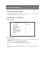
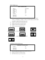
8.2 OSD (On Screen Display)
Main Menu Display
MAIN MENU
V.9729
LENS TYPE
EXPOSURE
WHITE BALANCE
PRIVACY MASK
EFFECT
NOISE REDUCTION
MOTION DETECT
COMMUNICATION
DEFAULT
EXIT
MANUAL/DC
?
?
?
?
?
?
?
?
?
?
?
?
?
?
ON
Main Menu Setupß
ß In order to display the setup menu on the screen, set the menu command or press the
button panel.
• Use 匀
(T)/ 吀
(W) control buttons to select each item.
• Use ? (-- )/ ? (+
+ ) control buttons to change the data.
• Use MENU control button to ENTER/ EXIT the menu display.
<Note>
For maximum image quality it is suggested to use DC LENS PENTAX TS812E 8mm
1:1.2 CS.
16
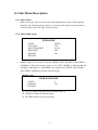
8.3 Sub Menu Description
8.3.1 LENS TYPE
Built-in DC-type Vari-Focal lens with ICR (although the camera OSD supports
both DC-type and Manual-type lenses, it is fixed to DC type because the camera
is built-in only with a DC-type Vari-Focal lens).
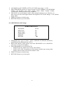
8.3.2 EXPOSURE Setup
EXPOSURE
MODE
AGC MAX
SHUTTER SPEED
DESS MAX
DEFAULT
RETURN
[WDR]
128
AUTO
OFF
ON
1. MODE: There are four types of modes: [WDR] / [BLC SMART] / [BLCUSER] /
[NORMAL]. When the function option is set to BLC SMART, it indicates that the
backlight compensation is calculated by the system. Press MENU under [WDR] /
[BLCUSER] / [NORMAL] mode to enter next page.
[WDR] Setup:
WDR EXPOSURE
LEVEL
DEFAULT
RETURN
8
ON
(1) LEVEL: Setup range from 0-40 (Default Setup: 8).
(2) DEFAULT: Return to Default Setup.
(3) RETURN: Return to previous status.
17
[BLCUSER] Setup:
BLC EXPOSURE
AREA
START X
END X
START Y
END Y
LEVEL
DEFAULT
RETURN
CENTER
NA
NA
NA
NA
7
ON
(1)
AREA: Setup to BLC, the area is set as BLC area and under manual
(2)
(3)
(4)
(5)
mode (1) CENTER (2) TOPS (3) TOPL (4) BOTTOMS (5) BOTTOML
(6) LEFT (7) RIGHT (Default Setup: NA).
START X: Horizontal start position (NA).
END X: Horizontal end position (NA).
START Y: Vertical start position (NA).
END Y: Vertical end position (NA).
(1) CENTER
(2) TOPS
(4) BOTTOMS
(3) TOP L
(5) BOTTOML
(6)LEFT
(1) RIGHT
[NORMAL] EXPOSURE Setup:
NORMAL EXPOSURE
LEVEL
DEFAULT
RETURN
(1)
(2)
(3)
96
ON
LEVEL: Setup range from 0-255 (Default Setup: 96).
DEFAULT: Return to Default Setup.
RETURN: Return to previous status.
18
2. AGC MAX: Set AGC MODE to AUTO, AGC MAX setup range = 0~255.
3. SHUTTER SPEED consists of 9 types of modes: AUTO, NORMAL, FLICKERLESS
(NTSC: 1/60 and PAL: 1/50), 1/250, 1/1000, 1/2000, 1/4000, 1/10000, 1/20000,
1/50000 and 1/100000 (Default Setup: NORMAL).
4. DSS MAX: Low speed shutter control, offers optimal brightness level. Therefore, in
dark scene, raise the value higher than the the brightness level (Field Range: 2~256, Default
Setup: OFF).
5. DEFAULT: Return to default setup.
6. RETURN: Return to previous status.
8.3.4 WHITE BALANCE Setup:
WHITE BALANCE
WB MODE
RED GAIN
BLUE GAIN
PUSH AUTO
DEFAULT
RETURN
AUTO
NA
NA
NA
ON
s
t
1. WB MODE: Five types of mode - AUTO, INDOOR, OUTDOOR, MANUAL,
and PUSH AUTO (Default Setup: AUTO).
2. RED GAIN/ BLUE GAIN operate only when WB MODE is set to MANUAL,
otherwise it is NA (Not Available).
3. When WB MODE is set to PUSH AUTO:
• PUSH AUTO ON: Enable auto tracing white balance.
• PUSH AUTO OFF: Depending on environment, disable auto tracing white
balance and record the current white balance value.
4. DEFAULT: Return to default setup.
5. RETURN: Return to previous status.
19
8.3.5 PRIVACY MASK Setup:
PRIVACY MASK
AREA
MASK
START X
END X
START Y
END Y
DEFAULT
RETURN
1
OFF
20
70
20
30
ON
s
t
1. AREA: Maximum PRIVACY MASK area setting is 15 (Default Setup: 1).
2. MASK: Set MASK to “ON”, MASK AREA becomes available for setup and is
shown on the monitor (Default Setup: OFF).
3.
4.
5.
6.
7.
8.
START X: Horizontal start position (0~240).
END X: Horizontal end position (0~240).
START Y: Vertical start position (0~150).
END Y: Vertical end position (0~150).
DEFAULT: Return to default setup.
RETURN: Return to previous status.
Note:
When the privacy mask has been enabled the motion area that has been covered by the
privacy mask becomes ineffective.
20
8.3.6 EFFECT Setup:
EFFECT
s
t
8
POSI
OFF
OFF
INT
NA
s
t
ENG
ON
s
t
DISPLAY
SHARPNESS
POSI/NEGA
MIRROR
FREEZE
SYNC
V PHASE
IRIS ADJ
LANGUAGE
DEFAULT
RETURN
1. DISPLAY: Under this menu, a user can decide whether to reveal or hide
TITLE DISP/ TITLE POS/ ID DISP/ ID POS/ ZOOM DISP/ ZOOM POS.
For more setup details on display, please follow the setup guide shown below:
DISPLAY Setup:
DISPLAY
TITLE
TITLE DISP
TITLE POS
ID DISP
ID POS
ZOOM DISP
ZOOM POS
DEFAULT
RETURN
~~~~~~~~~~~~~~~~~
ON
RIGHT DOWN
ON
RIGHT DOWN
ON
LEFT DOWN
ON
s
t
(1) TITLE: You can enter up to 16 characters.
!
0
?
“
1
#
$
% & ‘
2
3
4
@ A B C
5
(
6
)
7
D E
F
*
8
+
9
G H
,
:
I
;
J
<
.
/
=
>
K L
M
N O
P Q
R
S
T
U V W X Y
Z
[
\
]
^
_
`
a
b
c
d
e
f
g
h
i
j
k
l
m
n
o
p
Q r
s
t
u
v
w
x
y
z
{|
}
21
(2) Four TITLE Setup Positions (TITLE/ ID/ ZOOM):
RIGHT DOWN/ LEFT UP/ RIGHT UP/ LEFT DOWN (Default Setup: RIGHT
DOWN).
(3) Four ID Setup Positions:
RIGHT DOWN/ LEFT UP/ RIGHT UP / LEFT DOWN (Default Setup: RIGHT
DOWN).
(4) Four ZOOM Setup Positions:
RIGHT DOWN/ LEFT UP/ RIGHT UP/ LEFT DOWN (Default Setup:
RIGHT DOWN). Default Setup for Title/ ID/ ZOOM Display is “ON”.
(5) DEFAULT: Return to Default Setup.
(6) RETURN: Return to previous status.
2. SHARPNESS: Video sharpness level setup: 0 ~15 (Default Setup: 8).
3. POSI/ NEGA: Images can be set to POSI (Positive Image) or NEGA (Negative
Image). (Default Setup: POSI).
4. Four Types of MIRROR Mode: OFF/ HORIZONTAL/ VERTICAL/
ROTATE (Default Setup: Off).
5. FREEZE: Set FREEZE to “ON” to enable still field image (Default Setup: Off).
6. SYNC: Set to internal sync when using a DC 12V adaptor (Default Setup: INT).
And to line-lock sync when using an AC 24V adaptor.
7. V PHASE: When L/L mode is selected, you can adjust the desired phase (0 ~
358), otherwise it is an NA (Not Available) item (Default Setup: NA).
8. IRIS ADJ: When replacing the lens, face the camera toward the light, and then
Select the option “ADJ”. Message “ADJ…” means that adjustment is in progress, approx.
about 10 ~ 30 seconds afterward a message “ADJ OK” appears indicates that
the adjustment has been completed. When the message “Time Out” or “ADJ
ERR” appears indicates that the adjustment has failed.
9. LANGUAGE: Select English/ Chinese as your OSD language display.
10. DEFAULT: Return to Default Setup.
11. RETURN: Return to previous status.
22
8.3.7 NOISE REDUCTION Setup:
NOISE REDUCTION
NOISE REDUCE
REDUCE LEVEL
DEFAULT
RETURN
ON
MEDIUM
ON
s
t
1. Enable/Disable 2D/3D Digital Noise Reduction function (Default Setup: ON).
2. Adjust three-dimension noise reduction level values: HIGH/ MEDIUM/ LOW.
The higher the level, the better the noise reduction performance (Default Setup:
MEDIUM).
3. DEFAULT: Return to default setup.
4. RETURN: Return to previous status.
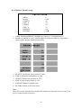
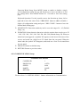
8.3.8 MOTION DETECT Setup:
MOTION DETECT
MOTION
AREA SET
SENSITIVITY
DURATION
DEFAULT
RETURN
OFF
猀
琀
10
5S
ON
猀
琀
1. MOTION: Motion detection setup ON/ OFF (Default Setup: OFF).
2. AREA SET: Motion detection area setup ON/ OFF (Default Setup: OFF).
DETECTION AREA Setup:
23
Detection Block Setup: Press MENU button to enable or disable a single
cell configuration setting Use up and down keys to move around or to end
the setting mode. Press MENU button for 3 seconds to leave the setting
page.
3.
4.
5.
6.
Keyboard Operation: Use the joystick to move the direction up, down, left or
right and to move the cursor. Press ? IRIS OPEN? button to enable or disable a
single cell configuration setting and press ? IRIS CLOSE? button to leave the
Motion Mask Setting page.
SENSITIVITY: Detection sensitivity can be set to the range of 0 ~ 63 (Default
Setup: 10).
DURATION: Alarm dura tion that arises after the motion alarm can be set to 5S
/ 10S / 15S / 20S / 30S / 1M / 2M / 3M / 4M / 5M (Default Setup: 5S). When an
alarm has been triggered, a symbols "M" appears on the lower-left corner of the
screen, and sends out a high Level 5V sound from the rear panel. When the
alarm ends, the symbol "M" disappears, and sends out a Low Level sound from
the rear panel.
DEFAULT: Return to default setup.
RETURN: Return to previous status.
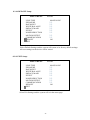
8.3.9 COMMUNICATION Setup:
COMMUNICATION
CAMERA ID
PROTOCOL
SPEED
PARITY
RETURN
1
AUTO
9600
NONE
猀
琀
Please refer to ? 6. INSTALLATION? formore information on Communication.
24
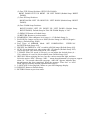
8.3.10 DEFAULT Setup:
MAIN MENU
V.9729
LENS TYPE
EXPOSURE
DAY/NIGHT
WHITE BALANCE
PRIVACY MASK
EFFECT
NOISE REDUCTION
MOTION DETECT
COMMUNICATION
> DEFAULT
EXIT
MANUAL/DC
?
?
?
?
?
?
?
?
?
?
?
?
?
?
?
?
ON
Select Default Settings and the system will return to its factory default settings.
All user settings on the device will be erased.
8.3.11 EXIT Setup:
MAIN MENU
V.9729
LENS TYPE
EXPOSURE
DAY/NIGHT
WHITE BALANCE
PRIVACY MASK
EFFECT
NOISE REDUCTION
MOTION DETECT
COMMUNICATION
DEFAULT
> EXIT
MANUAL/DC
?
?
?
?
?
?
?
?
?
?
?
?
?
?
?
?
ON
Select Exit Settings and the system will exit the menu page.
25
9. SPECIFICATION
Image Device
Picture Elements
1/3" Color H-Res. Vertical Double-Density WD CCD
(Sony Chipset)
NTSC: 976 x 494 (H x V) / PAL: 976 x 582 (H x V)
Resolution
Min. Illumination
650 TVL
(0.0017) Lux(Day mode), (0.00011) Lux (Night mode) / F1.2
S/N Ratio
More than 48dB
Electronic Shutter
NTSC:1/60~1/100,000, PAL:1/50~1/100,000
Flickerless Mode
On / Off (NTSC:1/100, PAL:1/120)
Iris Control
DC Drive
Lens Mount
Vari-Focal IR Lens
Digital Noise Reduction
LOW/MID/HIGH
Motion detection
24*16 detection blocks
Gamma
White Balance
0.45
Auto / Indoor / Outdoor / Manual / Push Auto
Gain Control
Back Light Comp.
Wide Dynamic Range
(WDR)
Auto / Manual
On / Off (Level & Area: user define and 7 default adjustable areas)
On / Off (Level adjustable), Auto detection
Day & Night (ICR)
Light Sensor
Digital Zoom
16x
Camera ID
000~255
Camera Title
Up to 16 characters
Mirror
Off / Horizontal / Vertical / Rotate
Privacy Masking
15 free areas (Area size adjustable)
Freeze
On / Off
Positive / Negative
On / Off
Digital Slow Shutter
(DSS)
Off, 2~20, 40, 80, 160, 256 FLD
Remote Control
RS-485 / RS-422
Protocol
PELCO D&P
Sync. System
Internal / External Line Lock (AC only)
Video Output
1 Vp-p / 75 Ohms
Power Supply
DC12 V DC12V/AC24V Dual (Option, available only to outdoor IR Dome)
Power Consumption
Operating Temp.
Dual: (5.28) W max.
-10?
~ 50?
26
1
Channel Vision Technology will repair or replace any defect in
material or workmanship which occurs during normal use of this
product with new or rebuilt parts, free of charge in the USA, for one
year from the date of original purchase. This is a no hassle warranty
with no mail in warranty card needed. This warranty does not cover
damages in shipment, failures caused by other products not supplied
by Channel Vision Technology, or failures due to accident, misuse,
abuse, or alteration of the equipment. This warranty is extended only
to the original purchaser, and a purchase receipt, invoice, or other
proof of original purchase date will be required before warranty
repairs are provided.
Mail in service can be obtained during the warranty period by calling
(800) 840-0288 toll free. A Return Authorization number must be
obtained in advance and can be marked on the outside of the shipping
carton.
This warranty gives you specific legal rights and you may have other
rights (which vary from state to state). If a problem with this product
develops during or after the warranty period, please contact Channel
Vision Technology, your dealer or any factory-authorized service center.
Channel Vision products are not intended for use in medical, lifesaving,
life sustaining or critical environment applications. Channel Vision
customers using or selling Channel Vision products for use in such
applications do so at their own risk and agree to fully indemnify Channel
Vision for any damages resulting from such improper use or sale.
500-301 Rev B