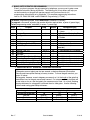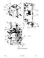
1
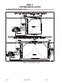
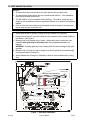
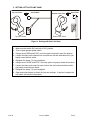
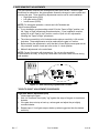
X3
ESTATE SERIES
INSTALLATION MANUAL
MODEL SW 2000-X3
HEAVY DUTY, HIGH CYCLE SWING GATE OPERATOR
MODEL SW 2000-X3 IS FOR VEHICULAR PASSAGE GATES
ONLY, NOT INTENDED FOR PEDESTRIAN PASSAGE GATE USE
3 YEAR WARRANTY
Serial # _____________________
(located on electrical box)
Installation Date ______________
TABLE OF CONTENTS
SAFETY SUMMARY ___________________________________________________________________1
BASIC INSTALLATION HINTS AND RULES ______________________________________________2
PART 1 SITE PREPARATION __________________________________________________________3
A. LOCATION AND LAYOUT ________________________________________________________________ 3
B. PAD AND MOUNT _______________________________________________________________________ 4
C. POWER WIRING_________________________________________________________________________ 5
D. LOOP DETECTORS AND PHOTO-SENSORS _________________________________________________ 5
E. TELEPHONE CONNECTION _______________________________________________________________ 5
F. MASTER/SLAVE INTERCONNECTION (MASTER/SLAVE SYSTEM ONLY)_______________________ 5
G. OTHER CONNECTIONS __________________________________________________________________ 5
H. GROUNDING __________________________________________________________________ 5
PART 2 SY STEM INSTALLATION ______________________________________________________6
A. GATE AND PHOTO-SENSOR LAYOUT ______________________________________________________ 6
B. MOUNTING GATE OPERATOR ____________________________________________________________ 7
C. CONNECTING POWER ___________________________________________________________________ 7
D. RUNNING INPUT WIRING ________________________________________________________________ 8
E. SETTING GATE OPEN DIRECTION SWITCHES S2 AND S3 ____________________________________ 8
F. POWER UP PROCEDURE _________________________________________________________________ 9
G. USING MANUAL CONTROLS _____________________________________________________________ 9
H. GATE ARM INSTALLATION _____________________________________________________________ 10
I. SETTING LIMIT CAMS ___________________________________________________________________ 11
J. GATE SENSITIVITY ADJUSTMENTS ______________________________________________________ 13
K. CONNECTING INPUT WIRING ___________________________________________________________ 15
L. BASIC GATE OPERATOR PROGRAMMING_________________________________________________ 17
M. POST INSTALLATION PROCEDURES _____________________________________________________ 18
N. FINAL ASSEMBLY OF GATE OPERATOR __________________________________________________ 22
O. PROGRAMMING THE RADIO RECEIVER __________________________________________________ 23
PART 3 LIFTMASTER LOOP DETECTOR BOARDS (OPTIONAL) __________________________24
PART 4 TROUBLESHOOTING AND MAINTENANCE ____________________________________25
A. TROUBLESHOOTING ___________________________________________________________________ 25
B. FAULT LIST ___________________________________________________________________________ 28
C. FAULTS AND THEIR CAUSES ____________________________________________________________ 29
D. MAINTENANCE ________________________________________________________________________ 30
APPENDIX A: SYSTEM OPERATION REFERENCE ______________________________________33
APPENDIX B: SW 2000-X3 PARTS LIST _________________________________________________38
GLOSSARY__________________________________________________________________________40
FCC REQUIREMENTS________________________________________________________________41
NOTICE TO CANADIAN USERS _______________________________________________________42
Rev
F
Doc 01-20099
TABLE OF FIGURES
Figure 1. Gate Operator Layout Options____________________________________________________ 3
Figure 2. Pad and Mount. _______________________________________________________________ 4
Figure 3. Photo-Sensor Layout ___________________________________________________________ 6
Figure 4. AC Wiring____________________________________________________________________ 7
Figure 5. Gate Direction and UPS Low Battery Switch Locations. ________________________________ 8
Figure 6. Manual Controls, Location and Use. _______________________________________________ 9
Figure 7. Gate Arm Installation__________________________________________________________ 10
Figure 8. Setting Right Gate Limit Cam ___________________________________________________ 11
Figure 9. Setting Left Gate Limit Cam_____________________________________________________ 12
Figure 10. Gate Sensitivity Adjustments Location. ___________________________________________ 13
Figure 11. Control Board Wiring _________________________________________________________ 15
Figure 12. Photo-Sensor Coverage Areas __________________________________________________ 20
Figure 13. Gate Operator Final Assembly__________________________________________________ 22
Figure 14. Programming The Radio Receiver__________________________________ 23
Figure 15. Programming The Radio Receiver ________________________________________ 23
Figure 16. Programming The Radio Receiver_______________________________________________________________ 23
Figure 17. Gate Operator Final Assembly__________________________________________________ 24
Figure 18. Gate Operator Disassembly and Assembly. ________________________________________ 31
Figure 19. Exploded View_______________________________________________________________ 39
Doc 01-20099
RevMF
The LiftMaster Gate Operator Model SW 2000-X3
The LiftMaster Gate Operator model SW 2000-X3 is a full featured, commercial swing gate
operator with a telephone interface. The gate operator contains the following features:
•
•
•
•
•
•
•
•
•
•
•
•
•
•
•
•
•
•
•
•
•
•
•
•
•
•
•
•
•
•
•
•
•
Rev
Satisfies U.L. 325 requirements for primary (motor current) and secondary (photo) obstruction
senses.
Five different open inputs are available for a variety of devices.
Dynamic motor braking limits gate overtravel.
Separated arm segment joints reduce the risk of injury to users.
Alternate action OPEN/CLOSE inputs.
Manual Open/Close/Stop inputs are provided for three-button station.
Programmable Reclose timer.
Gate lock relay can be used for electromagnetic locks and CCTV cameras or lights.
Master-Slave operation for two operators on bi-part gates and vehicle trap gates.
Selectable anti-tailgate function prevents two cars from entering on one open command.
Open motor detection in case of motor thermal overload.
Maximum Run Time feature stops run-away motor in case of belt breakage.
Senses obstructions through adjustable peak and fixed average motor current sense.
Two separate peak motor current sense adjustments for reversing direction or stopping; one
for clockwise motion and the other for counterclockwise motion.
Start-up current sense adjustment offsets initial inrush current to the motor.
Obstruction Alarm sounds off the second time the gate is obstructed.
Interrupt Bar input is included for use with edge sensors.
Cycle counter is able to initiate a service request call at a predetermined number.
Event recording memory keeps track of all commands and actions even during power
interruptions. This is very helpful in troubleshooting the system. Can be retrieved by modem into
your computer.
Automatic service request call is activated in the event of a fault or warning condition. A call
can be made to any telephone or pager and will include system ID number and fault condition
code.
12-button keypad and 7-segment display to facilitate programming, service and operation.
Automatic OPEN/CLOSE and Alert Call schedules include holidays.
Two 115 VAC accessory plugs provided.
24 VAC accessory power provided.
True ½ HP high starting torque motor reduces stalling.
80:1 worm gear reduction.
Handles any gate weight up to 1000 pounds and length up to 18 feet.
Diagnostic LEDs on controller board show gate operator actions and assist in troubleshooting.
Remote telephone interface permitting gate operator programming and diagnostics.
Inside and Outside Interrupt Loops and Photo Sensor Inputs enhance gate control and
distinguish between entering and exiting traffic.
Quick disconnect arm cap for fast and easy release of gate arm.
Cover access door provides easy access to the control box.
Optional loop detector add-on boards plug into the controller board, reducing wiring.
DIMENSIONS
WEIGHT
ELECTRICAL
Height 24”
Width 20”
Depth 23”
159 Lb.
115 VAC, 60 Hz. Single Phase
15 amp (A separate 20 AMP circuit
is required by most codes.)
F
Doc 01-20099
SAFETY SUMMARY
It is important for everyone involved in the installation and operation of the Gate Operator to
read the following warnings.
WARNING!
1. READ AND FOLLOW ALL INSTRUCTIONS. Improper installation of a gate operator
can result in a dangerous system. SAVE THESE INSTRUCTIONS.
2. A vehicle gate is a large, heavy object that is moved by an electric motor. A moving
gate can cause serious injury or death! The safety and well-being of others depends
on the installation of a safe system.
3. The entrance is for VEHICLES ONLY. Pedestrians must use a separate entrance.
Always keep people and objects away from the gate. NO ONE SHOULD CROSS THE
PATH OF THE MOVING GATE.
4. Choose one or more controls that together will allow complete control of the gate.
Most importantly, the gate must be able to be stopped at all times in case of
emergency, and the emergency control should be conveniently located, clearly
marked and visible.
5. All controls must be kept out of the reach of small children. Serious injury or death
can result from children playing with the controls.
6. All controls should be located so the person operating them can see the full area of
gate movement.
7. Use the emergency release only when the gate is not moving.
8. KEEP GATES PROPERLY MAINTAINED. Have a qualified person make repairs to the
gate hardware.
Test the gate operator safety features monthly. The gate MUST reverse on
contact with a rigid object or stop when an object activates the non-contact
sensors.
After adjusting the force or the limit of travel, retest the gate operator. Failure
to adjust and retest the gate operator properly can increase the risk of
damage, injury or death.
9. Gate operators and associated control equipment should be installed by qualified
professional installers who should observe the following safe installation
procedures:
Power should always be disconnected whenever installing, wiring or servicing a gate
operator. Moving chains in gate operators can catch clothing or fingers and cause
severe injury.
Installation of wiring should comply with local building and electrical codes.
All manual gate locks should be disabled to avoid damage to the gate or gate operator
should the lock become engaged after the operator is installed.
All operator controls and safety equipment should be tested at the conclusion of
installation to be sure they are functioning properly.
The operation of the gate controls and safety equipment should be reviewed with the
owner and/or end user of the automated gate system. They should also be informed
of the need to maintain control and safety equipment on a regular basis. Safety
equipment should be checked monthly to ensure it is working properly. All
installation manuals and safety information should be left with the owner.
Moving gates have pinch points and entrapment zones which can be extremely
dangerous to pedestrians, especially small children.
Rev
F
Doc 01-20099
1 of 42
BASIC INSTALLATION HINTS AND RULES
READ THIS SECTION CAREFULLY BEFORE BEGINNING YOUR INSTALLATION.
1. UNDERSTAND THE SYSTEM AND INSTALLATION SITE THOROUGHLY. The SW
2000 is a flexible and reliable gate operator system, but the quality of service depends
directly on the quality of installation. Please read these instructions carefully and study the
applicable diagrams before planning your installation. In particular, understand any site
characteristics that may affect the system installation.
WARNING
2. INSTALL PERMANENT WIRING. UL specifications require the SW 2000 system to be
permanently wired. Refer to your local wiring code for specific information.
WARNING: Damage caused by faulty wiring is not covered by warranty.
3. U.L. OBSTRUCTION-SENSING REQUIREMENTS. To maximize safety, U.L. 325
standards require primary obstruction sensing (gate sensitivity to impact) and secondary
obstruction sensing (photo-sensors) be in operation at all times.
4. GROUND THE SYSTEM. The system contains parts which may be damaged by static
discharge. A proper earth ground connected to the gate operator housing at the lower left
grounding screw (see Figure 12) will significantly reduce the chances of damage or
improper operation. The shielding in the cables specified for all remote sensors and
controls should also be connected to earth ground at the controller end of the cable only.
To be effective, the ground connection must be made by running 12 AWG copper wire to a
good ground point (e.g., an electrical panel, a metallic cold water pipe that runs into the
earth, or a grounding rod at least 10 feet in length that is driven into the earth) within 12
feet of the system. Even if you have a good earth ground, you should try to discharge any
static before handling the circuit boards.
WARNING: Damage caused by static discharge and lightning is not covered by warranty.
5. PROVIDE POWER FROM A DEDICATED SOURCE. The outlet into which you connect
the Gate Operator should be wired to its own circuit breaker to reduce line noise and
minimize the risk of having other equipment interrupt system operation. In a Master/Slave
system, Master and Slave must each have separate circuits.
6. DO NOT OVERLOAD THE TERMINAL BLOCKS. The terminal blocks are removable and
the pins are soldered into the boards. To connect your wires, remove the "head" from the
correct terminals and loosen the screws. Insert the wire into the correct opening on the
front and tighten the screw until the wire is held firmly. When you have made all
connections for a given "head", plug it back onto the pins designated for that terminal
block.
Stranded wire must be between 16 and 24 AWG. Solid wire must be between 18 and 24
AWG. This is the total thickness measurement so, if you are putting two wires in, the
combined thickness must fall within this range. NEVER try to insert more than two wires
per terminal.
7. ENSURE GOOD CONNECTIONS. A light tug on the wire will tell you if the connection is
secure. When reconnecting system components, make sure all pins are straight on chips,
connectors, and terminal block heads.
8. READ THE MARKINGS CAREFULLY. The connection points are marked on the boards
clearly. Before making any connection, be sure to read the marking and check it against
the corresponding figure in these instructions.
9. TRAIN YOUR CUSTOMERS THOROUGHLY. Although customer responsibility is limited
to proper installation, the quality of service is determined by the care of system setup.
Ensure that the customer has a copy of this manual to guide them.
2 of 42
Doc 01-20099
Rev F
PART 1
SITE PREPARATION
A. LOCATION AND LAYOUT
Figure 1. Gate Operator Layout Options
Rev
F
Doc 01-20099
3 of 42
•
•
NOTES
Left Gate and Right Gate are determined by looking from inside the complex toward
the street.
Figure 1 shows a typical Bi-Parting gate in standard and compact installations.
1. Always install gate operators inside of the fence line, NEVER on the public side of
the fence.
2. Mount all manual controls and activating devices at least 6 ft. away from the gate
for safety.
3. Allow enough clearance around the gate and the gate operator for installation and
service.
B. PAD AND MOUNT
Figure 2. Pad and Mount.
1. The concrete pad must be sufficient to support the gate operator and the dynamic
forces created by the moving gate. LiftMaster recommends a pad 24” wide by 27”
long by 30” deep.
2. The operator must be level and parallel to the gate, so the pad should be level and
about 4” above grade to prevent water entrance.
3. Four anchor bolts are required to secure the gate operator to the pad. The
mounting holes in the gate operator are 5/8” in diameter. Red Head bolts ½” x 3½“
are recommended.
4. Be sure to provide access for wiring conduits. In Master/Slave systems, remember
to include conduit stubs for separate inputs (if any) and for the Master/Slave
connection cable between gate operators. For more information about
Master/Slave systems, see Master/Slave Systems for X3 Series Gate Operators.
NOTE: Shading indicates conduit stub access areas.
4 of 42
Doc 01-20099
Rev F
C. POWER WIRING
1. Provide a separate conduit stub for the AC power.
2. Each gate operator requires a 115 VAC 20 AMP single phase circuit
NOTE: Master and Slave units each require separate circuits to prevent false
overcurrent faults (see X3 Series Master/Slave Systems).
3. Wiring must comply with the local Electrical Code for operating a 1/2 HP motor. 12
AWG for up to 300' and 10 AWG for up to 500' long wire runs is suggested.
4. Be sure to pull a ground wire in the conduit for the connection to the gate operator.
NOTE: Do not rely on metallic conduit for earth ground.
D. LOOP DETECTORS AND PHOTO-SENSORS
1. A shelf is provided (10" x 11" x 18" high) to support non-LiftMaster loop detector
electronics. Power for the loop detector can come from the auxiliary 115 VAC plugs
in the gate operator or from the 24 VAC provided by the gate operator control board.
NOTE: The auxiliary plugs have power regardless of the unit power switch setting.
2. Conduit provisions should be made for the “loop” wire entrance to the loop detector.
3. Wiring should be 16-24 AWG stranded or 18-24 AWG solid.
NOTE: Optional LiftMaster-supplied loop detector add-on boards are available, both
pre-installed and for installation in the field. See Part 3, Gate Operator Options.
E. TELEPHONE CONNECTION
1. A conduit entrance into the gate operator should be provided for the telephone line.
2. A single twisted pair wire 18 AWG to 24 AWG, will be connected from the telephone
company termination block through the conduit to J9 on the control board. Polarity is not
important.
NOTE: Do not run telephone and AC power wires in the same conduit.
F. MASTER/SLAVE INTERCONNECTION (MASTER/SLAVE SYSTEM ONLY)
1. A conduit between the Master and Slave units should be provided for the Master/Slave
interconnection cable.
2. Two shielded twisted pair wire 16 AWG to 24 AWG will be connected between the two
units at TB1 on the controller board.
NOTES: 1. Do not run the Master/Slave cable and AC power wires in the same conduit.
2. Master/Slave interconnection cable should not exceed 3000' in length.
G. OTHER CONNECTIONS
1. Provisions should be made for conduit entrance into the gate operator for external
activation devices such as key switches, telephone entry systems, loops, etc.
2. Wire size requirement: 16-24 AWG stranded or 18-24 AWG solid wire should be used.
H. GROUNDING
1. The system contains parts which may be damaged by static discharge. A proper earth
ground connected to the gate operator housing will significantly reduce the chances of
damage or improper operation. The shielding in the cables specified for all remote
sensors and controls should also be connected to earth ground at the controller end of
the cable only.
2. To be effective, the ground connection must be made by running 12 AWG copper wire
to a good ground point (e.g., an electrical panel, a metallic cold water pipe that runs into
the earth, or a grounding rod at least 10' in length that is driven into the earth) within 12'
of the system. Even if you have a good earth ground, you should try to discharge any
static before handling the boards.
Rev F
Doc 01-20099
5 of 42
PART 2
SYSTEM INSTALLATION
A. GATE AND PHOTO-SENSOR LAYOUT
Figure 3. Photo-Sensor Layout
6 of 42
Doc 01-20099
Rev F
IMPORTANT NOTE
The installation shown in Figure 3 is a suggested layout using emitters and receivers. Any
UL-approved photo-sensors are acceptable, but they must cover the entire area of gate
travel to be effective.
1.
Install photo-sensors in three Coverage Areas as shown in Figure 3.
Coverage Area A- Inside-Open Coverage:
Inside the gate, from the gate post(s) to the gate fully open position(s).
Coverage Area B- Inside-Closed Coverage:
Inside the gate, from the gate open position across full arc of gate travel.
Coverage Area C- Outside-Closed Coverage:
Single Gates: Outside the gate, from the gate post to the fence.
Dual Gates: Outside the gate, from gate post to gate post.
2.
For wiring instructions, see Paragraph K, Connecting Input Wiring, below.
NOTE: If you are installing a Master/Slave system, refer to Series X3 Master/Slave Systems
for additional layout information.
B. MOUNTING GATE OPERATOR
WARNING
To avoid injury, always turn off the unit power switch before working on gate.
1. Pull red release lever to disengage and remove quick disconnect arm cap from the output
shaft (see Figure 7).
2. Remove 4 protective bolts holding the cover on, lift off the cover and set aside.
3. Remove the assembly kit and parts.
4. Remove the 4 bolts that attach the gate operator to the shipping pallet.
5. Mount gate operator on cement pad using the previously installed anchors. Be sure the
operator is mounted level and square, with the control box facing away from the gate.
6. Connect the power conduit into the switch box.
7. Reinstall gate arm assembly onto output shaft/hub. Close red release lever until
engagement pin fully seats into hub and ball plunger engages on handle. This may require
slight side-to-side motion – HANDLE WILL CLOSE WHEN PIN IS PROPERLY ALIGNED –
DO NOT FORCE SHUT.
C. CONNECTING POWER
CAUTION
Ensure that the AC power circuit breaker is turned off
before wiring power to the switchbox.
Run power cables through the conduit to Gate Operator, then
connect wires to the switch box as shown in Figure 4:
1. Wire nut the hot (black) wire to the black pig tail.
2. Wire nut the neutral (white) wire to the white pig tail.
3. Wire nut the ground (green) wire to the green pig tail.
4. Dress all wiring inside the switch box and install cover.
Figure 4. AC Wiring
RevMF
Doc 01-20099
7 of 42
D. RUNNING INPUT WIRING
WARNING
Route but do not connect input wires at this time. If inputs are connected now, the
gate operator may activate at random during installation, potentially injuring installation
personnel.
1. Remove the plastic control box cover.
2. Run wires from input components conduits and Master/Slave conduits into control
box.
3. For Master/Slave wiring, refer to Master/Slave Systems for X3 Series Gate
Operators, Part 2.
E. SETTING GATE OPEN DIRECTION SWITCHES S2 AND S3
Figure 5. Gate Direction and UPS Low Battery Switch Locations.
NOTE: For swing gate operation, controls are Left/Clockwise and
Right/Counterclockwise.
•
Switch S2 sets gate opening direction (open to left or open to right).
•
Switch S2 is sensed only on power up, it should be set when the power is off, or
power should be cycled after setting the switch.
1. Set switch S2 to the Left for Clockwise Gate Opening, or to the Right for
Counterclockwise Gate Opening as required.
2. Set switch S3 to the direction you wish the gate to move (left or right) and remain
when the LOW BATTERY input is activated by an Uninterruptible Power Supply
(UPS).
8 of 42
Doc 01-20099
Rev F
F. POWER UP PROCEDURE
CAUTION
If gate is positioned at the 'open' limit, gate will automatically close if Relcose
Timer is enabled and power is switched on. Position gate either at the closed
limit or at no limit when preparing to switch power on. Always use extreme
caution and follow all warning in the Safety Summary.
1. Turn on circuit breaker that provides power to gate operator.
2. Turn on gate operator power switch and verify that the seven-segment LED display
above the keypad sequentially spells out “HELLO”. The only LEDs that should
remain on are MAGLOCK and CLOSE LIMIT or OPEN LIMIT, if one of the limit
switches is engaged.
NOTE: If the LEDs do not follow this pattern, the controller board may not be working
correctly. Stop installation and call LiftMaster Technical Support for assistance.
G. USING MANUAL CONTROLS
Figure 6. Manual Controls, Location and Use.
If necessary, use the manual controls on Manual Input Terminal TB2 (OPEN, CLOSE,
and STOP, as shown in Figure 6), to move the gate arm during system installation.
•
To open the gate: connect the OPEN and STOP terminals to the COMMON
terminal.
•
To close the gate: connect the CLOSE and STOP terminals to the COMMON
terminal.
•
To stop the gate: disconnect the STOP terminal to the COMMON terminal.
IMPORTANT NOTE
If the STOP terminal is disconnected from the COMMON terminal, the gate is
prevented from moving and no command will affect the gate.
RevMF
Doc 01-20099
9 of 42
H. GATE ARM INSTALLATION
NOTES:
1. All dimensions are measured from one pivot point to the next pivot point.
2. The dimensions shown above are only recommended settings. Your installation
may require different dimensions.
3. The SW 2000-X3 can be installed without welding. The anchor, swing arm and
drag link may be attached using the supplied hardware only, welded, or bolted and
welded.
4. Paint or other anti-rust coating must be applied to the cut areas of the swing arm
and/or drag link pipe to prevent rust.
1. Attach gate anchor to gate by welding or using hardware (not supplied).
2. Using manual controls, move the swing arm cap assembly until it points roughly to
the anchor. See Figure 7.
3. Measure and cut the swing arm to length. Attach swing arm to swing arm cap
assembly with gate stop on driveway side, using supplied hardware or by
welding.
WARNING: Installing gate stop on the wrong side will cause damage to the gate
operator.
4. Measure and cut Drag Link pipe to length, then insert spherical rod end assembly
into pipe and tighten locking nut.
5. Attach welded end of Drag Link Assembly to Anchor and unwelded end to Swing
Arm.
Quick Disconnect
Release Lever
Swing Arm Cap Assembly
Disengaged
Engaged
Figure 7. Gate Arm Installation
10 of 42
Doc 01-20099
Rev F
I. SETTING LIMIT CAMS
•
Adjust the limit cams by loosening the clamp and rotating the cams. The cams
rotate with the swing arm shaft, so small adjustments are magnified by the length
of the gate.
•
Use manual controls to move the gate during limit cam adjustment.
•
To avoid damage to the gate and gate operator due to the gate overrunning its
limits, perform the following steps carefully:
1. SETTING RIGHT GATE LIMIT CAMS
Top Limit Cam
Bottom Limit Cam
Open Gate
Closed Gate
Bottom Limit Switch
Top Limit Switch
01-20099F1
Figure 8. Setting Right Gate Limit Cam
1. Make sure that switch S2 is set to the "Right" position.
2. Turn on gate operator power switch.
3. Using manual CLOSE and STOP, move the gate to its proper closed limit position.
4. Loosen the clamp on the bottom limit cam and turn the cam clockwise until it just
barely closes the limit switch.
5. Retighten the clamp. Do not overtighten.
6. Using manual OPEN and STOP, move the gate to its proper open limit position.
7. Loosen the clamp on the top limit cam and turn the cam counterclockwise until it
just barely closes the limit switch.
8. Retighten the clamp. Do not overtighten.
9. Open and close the gate to check the limit cam settings. If required, readjust the
limit cams until they are set properly.
RevMF
Doc 01-20099
11 of 42
2. SETTING LEFT GATE LIMIT CAMS
Top Limit Cam
Closed Gate
Bottom Limit Cam
Top Limit Switch
Open Gate
Bottom Limit Switch
01-20099F2
Figure 9. Setting Left Gate Limit Cam
1. Make sure that switch S2 is set to the "Left" position.
2. Turn on gate operator power switch.
3. Using manual OPEN and STOP, move the gate to its proper open limit position.
4. Loosen the clamp on the bottom limit cam and turn the cam clockwise until it just
barely closes the limit switch.
5. Retighten the clamp. Do not overtighten.
6. Using manual CLOSE and STOP, move the gate to its proper closed limit position.
7. Loosen the clamp on the top limit cam and turn the cam counterclockwise until it
just barely closes the limit switch.
8. Retighten the clamp. Do not overtighten.
9. Open and close the gate to check the limit cam settings. If required, readjust the
limit cams until they are set properly.
12 of 42
Doc 01-20099
Rev F
J. GATE SENSITIVITY ADJUSTMENTS
The gate operator monitors both average and peak motor current. When the gate
encounters an obstruction, the gate operator senses the change in motor current and
reverses the gate. Three sensitivity adjustments must be set for each installation:
• Right gate motion (R69)
• Left gate motion (R160)
• Inrush current (R203)
NOTE: For swing gate operation, controls are Left/Clockwise and
Right/Counterclockwise.
♦ If your installation requires setting switch S2 to the “Open to Right” position, use
the “Open to Right" adjustment procedures below. If your installation requires
setting S2 to the “Open to Left” position, use the “Open to Left" adjustments
following the "Open to Right" procedures.
♦ The minimum sensitivity is full clockwise and maximum sensitivity is full counter
clockwise. These adjustments must be made while the gate is in motion.
♦ Before starting the adjustments, verify that the Left and Right reverse pots are set
fully clockwise, and the Inrush pot is set to the 11 o’clock position.
♦ Make all adjustments in the order listed.
NOTE: Current flow varies with temperature. Do not tune the sensitivity
measurements too finely, or they may cause false overcurrent faults to occur during
cold weather.
Figure 10. Gate Sensitivity Adjustments Location.
"OPEN TO RIGHT" ADJUSTMENT PROCEDURES
Right Gate Motion Adjustment (R69)
1. Initiate opening the gate.
2. Wait 4 to 5 seconds, then lightly "tug" against the edge of the gate to simulate an
obstacle.
3. If the gate does not stop or back up, reclose gate and adjust the pot slightly
counterclockwise.
4. Repeat steps 1-3 until gate stops or backs up when tugged and has the desired
sensitivity.
RevMF
Doc 01-20099
13 of 42
Left Gate Motion Adjustment (R160)
1. Open the gate fully, then initiate closing the gate.
2. Wait 4 to 5 seconds, then lightly "bump" the leading edge of the gate to simulate
an obstacle.
3. If the gate does not stop or back up, reopen the gate and adjust the pot slightly
counterclockwise.
4. Repeat steps 1-3 until the gate stops or backs up when bumped and has the
desired sensitivity.
"OPEN TO LEFT" ADJUSTMENT PROCEDURES
Left Gate Motion Adjustment (R160)
1. Initiate opening the gate.
2. Wait 4 to 5 seconds, then lightly "tug" against the edge of the gate to simulate an
obstacle.
3. If the gate does not stop or back up, reclose the gate and adjust the pot slightly
counterclockwise.
4. Repeat steps 1-3 until the gate stops or backs up when tugged and has the
desired sensitivity.
Right Gate Motion Adjustment (R69)
1. Open the gate fully, then initiate closing the gate.
2. Wait 4 to 5 seconds, then lightly "bump" the leading edge of the gate to simulate
an obstacle.
3. If the gate does not stop or back up, reopen the gate and adjust the pot slightly
counterclockwise.
4. Repeat steps 1-3 until the gate stops or backs up when bumped and has the
desired sensitivity.
INRUSH CURRENT ADJUSTMENT (R203)
1.
2.
3.
4.
5.
6.
Turn the pot fully counterclockwise.
Open the gate.
If the gate stops due to a fault condition, slightly adjust the pot clockwise.
Repeat steps 2 and 3 until the gate cycles without a fault.
Open gate fully, then initiate closing the gate.
If the gate stops or backs up due to a fault condition, slightly adjust the pot
clockwise.
7. Repeat steps 6 and 7 until the gate cycles without a fault and has the desired
sensitivity.
14 of 42
Doc 01-20099
Rev F
K. CONNECTING INPUT WIRING
LOOP
SENSOR
LOOP
SENSOR
OUTSIDE
INTERRUPT SENSE
LOOP
SENSOR
INSIDE
INTERRUPT SENSE
O
P
T
I
O
N
SHADOW SENSE
O
P
T
I
O
N
LOOP
SENSOR
EXIT SENSE
O
P
T
I
O
N
O
P
T
I
O
N
GROUND LUG
EXTERNAL GROUND
(SEE SITE PREPERATION)
1390F6
Figure 11. Control Board Wiring
Rev F
Doc 01-20099
15 of 42
IMPORTANT: Before proceeding, see NOTES below.
1. Wire all external control devices to their connections on the control board as
shown. See Appendix A for details on how each control input affects the gate
operator.
2. Connect the Master/Slave interconnect cable (see Master/Slave Systems for X3
Series Gate Operators, Part 1).
NOTES
1. Disconnecting the STOP terminal from the COMMON terminal stops the gate and prevents all
commands from having any effect. Manual Open does not activate the Reclose Timer.
IMPORTANT: As per UL325 standards, install the Manual Input and Fire switches in the
line of sight with the gate.
2. If gate(s) are used for bi-directional traffic, the Exit Loop should be a directional loop detector.
3. Inside and Outside Interrupt Loops:
♦ For maximum safety, Inside and Outside Interrupt loops require separate loop
detectors.
♦ Bi-part or Bi-part Latch: If only one loop detector is used, connect Outside loop to the
Inside loop detector.
4. Battery is used to store date and time.
16 of 42
Doc 01-20099
Rev F
L. BASIC GATE OPERATOR PROGRAMMING
Even if you plan to program the gate operator by telephone, you may want to enter some
immediate instructions during installation. The following list of instructions will help you
set basic controls so the gate will operate properly until you have time for full
programming, either directly or by telephone. For complete programming instructions,
refer to “SL 1000, SW 2000, and BG 3000-X3 Programming (-173 bd)”.
To access programming mode: enter QQQ 000000 (3 asterisks, 6 zeroes)
To program a command: a) enter step number b) enter required data c) enter # (pound sign)
To exit programming mode: enter 00# (2 zeroes, 1 pound sign)
Step
Purpose
Step
01
Gate Type
1
02
03
Operator Type
Pair Type
1
1
04
05
06
07
Not Used
Not Used
Anti-Tailgate Enable (ATG)
Latch Delay Time
1
3
08
09
10
11
12
13
14
15
Reclose Time (RT)
Not Used
Not Used
Obstruction Sense Backup Closing
Obstruction Sense Backup Opening
Interrupt Bar Backup If Closing
Interrupt Bar Backup If Opening
Return to Factory Set Defaults
•
Up to 3
Up to 3
Up to 3
Up to 3
Up to 3
6
Default
Acceptable Input
1
0 = Slide, 1 = Swing, 2 = Barrier,
3 = Linear
0
0 = Single, 1 = Master, 2 = Slave
0
0=Bipart, 1=Latch, 2=Not Used,
3=Tandem
0
0 = Disabled, 1 = Enabled
6
0 – 250 Seconds (.4 sec.
Increments)
30
0 – 250 Seconds (0 = Disabled)
12
12 – 499 Inches See note below.•
12
12 – 499 Inches See note below.•
12
12 – 499 Inches See note below.•
12
12 – 499 Inches See note below.•
N/A
101010 (partial), 191919 (full)
IMPORTANT NOTE: SWING GATE BACKUP DISTANCES
Slide gates move at about one foot per second, so backup distances (Obstruction
Senses and Interrupt Bar Backup) are easy to enter. To move the gate one foot, you
enter 12 inches.
Swing gates, however, move in degrees per second, so it is the length of the gate that
determines how far the gate moves each second. For instance, a twenty foot gate will
move twice as far as a ten foot gate in the same amount of time. As a result, entering
backup distances for swing gates is different than for slide gates. Use the following
table to enter swing gate backup distances:
I want my gate to move
this far out at the end:
One foot
Two feet
Three feet
Rev• F
10'
Enter 9"
Enter 18"
Enter 27"
Doc 01-20099
And my gate length is:
15'
20'
Enter 6"
Enter 3"
Enter 12"
Enter 6"
Enter 18"
Enter 9"
17 of 42
M. POST INSTALLATION PROCEDURES
1. Setup
1. Turn on the main power at the gate operator's circuit breaker.
2. Verify that switch S2 (the Gate Open Direction switch) is set to the correct
position.
3. Turn on the unit power switch.
2. Manual Inputs
1. Verify that Manual Open fully opens the gate and that the open limit switch
stops the gate.
2. Verify that Manual Close fully closes the gate and that the close limit switch
stops the gate.
3. Verify that Manual Stop stops the gate.
Note: If the gate stops due to an obstruction Fault, readjust the gate sensitivity
pots.
3. Mechanical
Use the Manual Input commands to verify that:
1. The gate swings open and closed smoothly.
2. There is no squeak or vibration in the gate when it is moving .
3. There is no belt slippage when the gate moves or stops.
4. There is no slack in the closed gate due to loose chain or parts.
5. Both gates open and close at the same time (Bi-Parting gates only).
4. Gate Sensitivity and Obstruction Alarm
(Primary Obstruction Sensing per UL 325 Requirements)
1. Left/Right Obstruction sensitivity:
Apply a bump to the opening and closing gate and verify that the gate stops or
reverses.
2. Start-Up Sensitivity:
Apply a bump to the gate as it starts moving and verify that the gate responds to
the bump within a second.
3. Obstruction Alarm:
Cause two obstruction faults before the gate reaches its open or closed limit
and verify that the Obstruction Alarm sounds.
5. Entry inputs
1. Activate the CYCLE input (entry system), RADIO input (radio transmitter), and
EXIT Loop input (driving over the exit loop) and verify that they fully open the
gate. If Reclose Timer is enabled, it will close the gate.
2. Activate the FIRE input (fire department switch) and verify that the gate fully
opens and then closes after 5 seconds. If Reclose Timer is enabled, it will close
the gate.
18 of 42
Doc 01-20099
Rev F
6. Alternate Action
If Alternate Action has been selected so that CYCLE or RADIO commands both
open and close the gate:
Activate the CYCLE command, wait until the gate is fully open, then activate the
CYCLE command again. The gate should close, verifying Alternate Action
operation.
Note: If you select Alternate Action, you can't enable ATG and RT in procedures 6
and 8.
7. Reclose Timer
If Reclose Timer has been enabled in programming step 8, verify Reclose Timer as
follows:
1. Activate any entry command (except Manual OPEN) to open the gate.
2. Start timing when the gate reaches fully open and verify that the Reclose Timer
recloses the gate after the desired interval.
NOTE: Reclose Timer is not functional when the Manual OPEN command is used.
8. Interrupt Loop and Anti-Tailgating (ATG) When Exiting
Gate Type is SWING (Enter 1 in Programming Step 01):
Inside Interrupt Loop: When a vehicle drives on the Interrupt Loop a moving
gate will stop. When the vehicle drives off the Interrupt loop, the gate will open.
Outside Interrupt Loop: When a vehicle drives on the Interrupt Loop a closing
gate will open (an opening gate will not be affected).
NOTE: ATG will not function with a Gate Type of SWING.
9. Shadow Loop
1. Ensure the gate is fully closed (the close limit switch and Maglock LED’s will be
ON).
2. Park a car, while it is running, on the Shadow Loop but clear of the Safety Loop.
3. Activate an Open command and verify that the gate does not open
CAUTION: If the gate begins to open, move the car immediately.
4. Remove the car from the Shadow Loop and verify that the Open command
opens the gate.
RevMF
Doc 01-20099
19 of 42
Figure 12. Photo-Sensor Coverage Areas
10. Photo-Sensors (Secondary Obstruction Sensing per UL 325 Requirements)
Refer to above figure for Photo-Sensor coverage areas.
Coverage Area A (Inside-Open Coverage): While the gate is moving, put your
hand or arm through the Inside Photo-Sensor beam. The gate should stop. The
gate should restart when the obstruction (your hand) is removed.
Coverage Area B (Inside-Closed Coverage): Stand inside the fence line. While
the gate is moving, put your hand or arm through the Outside Photo-Sensor
beam. The gate should stop. The gate should restart when the obstruction (your
hand) is removed.
Coverage Area C (Outside-Closed Coverage): Stand outside the fence line. While
the gate is closing, put your hand or arm through the Outside Photo-Sensor
beam. The gate should stop. The gate should restart when the obstruction (your
hand) is removed.
20 of 42
Doc 01-20099
Rev F
11. Interrupt Bar (Edge Sensor)
While the gate is opening, push on the Interrupt Bar (Edge Sensor). The gate
should stop and reverse a few inches.
12. Maglock
Verify that the Maglock activates when the gate is fully closed.
RevMF
Doc 01-20099
21 of 42
N. FINAL ASSEMBLY OF GATE OPERATOR
Figure 13. Gate Operator Final Assembly
IMPORTANT SAFETY PROCEDURE
1. Turn off power to the gate operator at the circuit breaker and wait for one
minute.
♦ Refer to Figure 13, above, to perform the following instructions.
2. Disconnect Drag Link from Anchor. Then disengage quick disconnect by pulling
the release lever on the Swing Arm Cap Assembly. Remove Swing Arm Cap
Assembly and Drag Link Assembly from drive shaft. Set this assembly aside.
3. Install clear cover on gate operator control box.
4. Make sure that gate operator unit power switch is turned on.
5. Install gate operator cover and secure with four bolts.
6. Replace Swing Arm Cap Assembly and Drag Link Assembly on drive shaft, then
reconnect Drag Link to gate Anchor.
7. Reinstall gate arm assembly onto output shaft/hub. Close red release lever until
engagement pin fully seats into hub and ball plunger engages on handle. This
may require slight side-to-side motion – HANDLE WILL CLOSE WHEN PIN IS
PROPERLY ALIGNED – DO NOT FORCE SHUT.
8. Turn on power to the gate operator at the circuit breaker.
9. Cycle the gate to ensure it is operating properly.
22 of 42
Doc 01-20099
Rev F
PART 3
LIFTMASTER LOOP DETECTOR BOARDS (OPTIONAL)
The gate operator model SW 2000-X3 has connectors for four LiftMaster-supplied loop
detector add-on boards. These boards simply plug into the control board and interface with
Interrupt, Shadow and Exit loop sensors. The add-on boards can be ordered pre-installed,
or can be installed in existing model SW 2000-X3 units.
Exit Loop
Inside Interrupt Loop
SW 2000
Fence
Shadow Loop
Swing Gate
Fence
Outside Interrupt Loop
1387F3
Figure 17. Typical Swing Gate Loop Detector Configuration.
24MofM42
Doc 01-20099
RevoF
PART 4
TROUBLESHOOTING AND MAINTENANCE
A. TROUBLESHOOTING
This section is designed to help you troubleshoot your unit(s) with a minimum. Below are
some hints to help:
Test the Operator
Quick Reference List of Faults and Methods to Resolve
Quick Reference List of Faults and Causes
Testing Control Board inputs: To test an input, connect the input terminal to the
COMMON terminal on the Control Board and verify that its LED turns on
momentarily. Normally, the Close limit switch and Maglock LED's are on if the gate
is fully closed, and Open limit switch is on if the gate is fully open. The Manual
STOP LED is always on.
Low input AC voltage: The voltage across connector J1 pins 1 (red wire) and 3
(white wire) on the Control Board must measure 100VAC to 130VAC.
CAUTION HIGH VOLTAGE. Measure with care.
Fault Causes: Refer to the end of trouble shooting section.
1. OPERATOR IS DEAD
When the unit power switch is cycled, the 7-segment display does not spell
out "HELLO" sequentially.
1. The main circuit breaker or unit power switch is off.
2. The input power connector is not connected securely to the Control Board.
3. Low input AC voltage.
4. Bad Control Board.
2. OPERATOR DOES NOT RUN
When the unit power switch is turned on, the 7-segment display spells out
"HELLO" sequentially.
1. An input is continuously activated (stuck).
2. Both limit switches are stuck closed.
3. Manual Stop is disconnected from its common.
4. Stalled motor.
3. MOTOR DOES NOT RUN
Motor is dead:
1. The resettable motor thermal overload switch has popped.
2. The interconnecting cable between the motor and the control board is
disconnected.
3. Bad control board or motor.
Motor is stalled:
1. Frozen motor, gearbox or gate.
2. V-belt is too tight.
Rev F
Doc 01-20099
25 of 44
4. THE CONTROL BOARD RESETS RIGHT AFTER GATE STARTS MOVING
1. Low AC voltage.
2. Inadequate and undersized power wiring between the main circuit breaker and the gate
operator.
5. GATE STOPS AND REVERSES IMMEDIATELY AFTER IT STARTS
1. A Fault has occurred.
Mostly in cold weather or mornings:
2. A Fault has occurred; Inrush pot adjustment is set too low.
6. GATE STOPS A FEW SECONDS AFTER IT STARTS
1. Stuck limit switch.
2. A Fault has occurred.
7. GATE SUDDENLY REVERSES WHILE MOVING
A Fault has occurred.
8. OPENING GATE STOPS WHEN A VEHICLE APPROACHES FROM INSIDE
Setting the Gate Type to SWING or LINEAR, causes Interrupt loops or photo-sensors to
stop the gate when a vehicle approaches from the inside. For safety reasons, the gate
normally operates this way.
9. GATE OPENS BUT DOES NOT CLOSE
1. Reclose Timer is disabled.
2. One of the inputs is continuously activated (a stuck input).
3. Entry system is connected to the Manual Open input.
10. GATE DOESN'T STOP AT THE LIMIT
1. Limit cams are out off adjustments.
2. Limit switch cable is disconnected either from the control board or the limit switches.
3. Bad limit switch or limit cam or limit switch bracket.
11. GATE IS TOO SLOW
1. Low input AC voltage
2. Hardened or frozen gate hinges.
3. Slipping belt.
12. GATE DOESN'T STAY OPEN WHEN USING FIRE INPUT
Fire was only activated momentarily—not continuously.
26MofM42
Doc 01-20099
RevMF
13. GATE DOES NOT CLOSE AUTOMATICALLY
1. Reclose timer is disabled.
2. The entry system is connected to Manual Open input.
3. An input is continuously activated (stuck).
14. ALTERNATE ACTION DOES NOT WORK
1. ATG and Reclose Timer are enabled.
2. Entry system is connected to the Manual Open input.
15. GATE DOES NOT OPEN TO THE CORRECT DIRECTION
1. The power was not cycled after changing the setting of switch S2.
16. THERE IS SLACK OR PLAY IN THE GATE
1.
2.
3.
4.
Chain is too loose.
The hardware interconnecting the operator to the gate is not tight.
The large mounting bolt or the jam nut for the cap arm are not tight.
Set screws on the sprocket is not tight.
17. ATG (ANTI-TAILGATE) DOES NOT WORK
For safety reasons, ATG is not functional with Gate Types SWING and LINEAR.
18. INTERRUPT LOOP DOES NOT ACT PROPERLY
1. Improper Gate Type setting (programming step 1).
2. Bad loop sensor or loop detector.
3. Bad connection between the loop sensor, loop detector and the Control Board.
19. SHADOW LOOP IS INEFFECTIVE
1. The gate is not at either the open or close limit.
2. Bad loop sensor or loop detector.
3. Bad connection between the loop sensor, loop detector and the Control Board.
20. Maglock does not work
1.
2.
3.
4.
Bad connection between Maglock, its power supply and the Control Board.
Bad Control Board (relay on the Control Board does not close).
Bad Maglock or Maglock power supply.
Large gap between gates.
21. MASTER/SLAVE SYSTEM
Units work as stand-alone:
1. Miswired or disconnected Master/Slave interconnect cable.
2. Improper Master/Slave program settings.
3. Bad control board.
27 of 42
Doc 01-20099
Rev F
Units are not synchronized:
Improper Master/Slave program settings.
One gate braking to stop causes a fault in the other (moving) gate:
1. Both units are wired to the same circuit breaker.
2. Undersized power wires.
B. FAULT LIST
The following conditions can cause a fault:
1. Instantaneous motor overcurrent (left/right obstruction sense) due to an
object physically obstructing the gate or gate track (UL325 requirement).
2. Average motor overcurrent (overload) caused by excessive motor
current (UL325 requirement).
3. Interrupt Bar activation (edge sensor) due to physical contact with the
edge sensor.
4. Inoperative motor caused by an open motor winding, broken or
disconnnected input motor wires, thermal overload, or unsupervised motor
(UL325 requirement).
5. Limit switch staying closed when gate is supposed to move, caused
by a broken V-belt, defective limit switch, or defective limit cams.
6. Maximum motor run time exceeding 75 seconds.
A. If faults 1 through 3 occur only once during opening or closing, the gate
reverses a few inches and stops. Fault may be cleared by removing the
obstruction and cycling any command (Manual Inputs, FIRE, Cycle, Radio,
EXIT).
B. If two sequential faults (a combination of faults 1 through 3 and PhotoSensor activation) occur during opening or closing, gate stops and
Obstruction Alarm sounds off for 5 minutes. Fault may be cleared by
removing the obstruction and cycling Manual Inputs or FIRE.
C. If fault 4 occurs, gate stops and Obstruction Alarm sounds off for 5 minutes.
Fault may be cleared by cycling Manual Inputs or FIRE.
D. If faults 5 through 6 occur, gate stops. Fault may be cleared by cycling any
command.
Rev
F
Doc 01-20099
28 of 42
C. FAULTS AND THEIR CAUSES
1. IF OBSTRUCTION LED IS ON
1. The gate is blocked by an object.
2. OBSTRUCTION or STARTUP adjustment is set too low.
3. Cold weather: frozen motor or frozen gate wheels.
4. The Maglock does not disengage from the gate at the start of gate opening.
5. A sudden increase in input power.
6. Bad Control board.
7. Belt is too tight.
2. IF INTERRUPT BAR LED IS TURNED ON
Edge Sensor is activated. Clear obstruction and cycle the gate.
3. IF OPEN MTR LED IS TURNED ON
1. The motor thermal overload switch is popped.
2. The wires connecting the motor to the Control Board are disconnected
3. Bad motor.
4. Bad Control Board.
4. IF STUCK-LIMIT LED IS TURNED ON
1. A limit switch is stuck closed.
2. The belt was broken before the start of the gate movement.
3. Stalled motor at open or close limit.
4. Bad limit switch.
5. IF MAX RUN TIME LED IS TURNED ON
1. Limit cams do not engage the limit switches.
2. The belt or chain has been broken.
3. The belt slips during gate movement.
4. Limit switch cable is disconnected.
5. Bad limit switch.
6. Stalled motor.
29 of 42
Doc 01-20099
Rev F
D. MAINTENANCE
WARNING
To avoid injury, always turn off the unit power switch before working on gate.
Regularly performance of preventive maintenance is essential for reliable system
operation because it corrects small problems before they turn into emergencies.
LiftMaster recommends performing preventive maintenance every 6 to 12 months,
depending upon the amount of gate usage.
•
If the gate is installed in a private residence or small apartment house where
usage is not severe, yearly preventive maintenance is acceptable.
•
If the gate is installed in a high-traffic application, semi-annual preventive
maintenance is essential.
PREVENTIVE MAINTENANCE TASKS
1. Gate Arm: Check for wear in the moving parts. Check for hardware tightness.
2. Gate: must swing freely without any impediment. Check hinges, grease if
necessary.
3. Chain: Check for wear and tension. If loose, adjust tension with chain tensioner.
Do not oil chain.
4. Sprocket: must not be loose in the shaft. Tighten set screws if loose ➊.
5. Limit switches: contacts must bounce back rapidly when they are pressed and
released.
6. Belt: Check for wear and tension (25 to 30 lb.). Adjust the AC motor up or down
to set proper tension.
7. Pulleys: must all line up and be firmly secured to their shafts. Tighten set
screws if loose ➊.
8. Gear Box: Check for no oil leakage around the bushings. Do not oil gearbox.
9. Control board: Check for water damage or burned spots. All connectors
secured to the board.
10. Wiring: Check all wiring for any insulation damage. Check for loose wire
connections.
11. No Rust: Check for rust throughout the unit. Check corners for water
entrapment.
12. Fire Open: Activate Fire department switch to verify emergency gate opening.
13. Gate Sense: Check for the gate sensitivity (refer to Part 2, System Installation,
paragraph J, Gate Sensitivity Adjustments).
14. Photo-Sensors: Ensure that sensor emitters/receivers are aligned and clean.
Verify that inputs stop gate.
15. Obstruction Alarm: Check for proper operation. Alarm must sound after two
consecutive gate obstruction faults.
NOTES:
➊: To prevent loosening, two set screws are used in each hole and Loctite
threadlocker 242 is applied.
Rev
F
Doc 01-20099
30 of 42
PREVENTIVE MAINTENANCE INSTRUCTIONS
Figure 18. Gate Operator Disassembly and Assembly.
♦ Refer to Figure 18, above, to perform the following instructions.
1. Turn off power to the gate operator at the circuit breaker and wait for one
minute.
2. Inspect Gate Arm (Swing Arm Cap Assembly, Swing Arm and Drag Link
Assembly) for wear and hardware tightness. Check (✓ ) its box in the Maintenance
Schedule.
3. Disconnect Drag Link from Anchor, then loosen mounting bolt and remove Swing
Arm Cap Assembly and Drag Link Assembly from drive shaft. Set this assembly
aside.
4. Push and pull the Gate to ensure it swings freely (grease if necessary). Check (✓ )
its box in the Maintenance Schedule.
5. Remove the cover mounting bolts and remove the gate operator cover.
6. Reinstall the Drag Link, Swing Arm and Swing Arm Cap Assemblies.
7. Perform preventive maintenance tasks 3 to 15.
8. After completing all checks, perform the procedure found in Part 2, System
Installation, paragraph N, Final Assembly of Gate Operator.
31 of 42
Doc 01-20099
Rev F
The following table is provided to help you keep a record of the maintenance schedule. Write the
inspection date in the left-hand box and check (✓ ) the boxes across as you perform your
maintenance procedures.
MAINTENANCE SCHEDULE TABLE
Date Arm Gate Chain Sprocket
RevMF
Limit
Belt Pulleys Gear Control Wiring No Fire Gate Obs.
Switches
box Board
Rust Open Sense Alm.
Doc 01-20099
32MofM42
APPENDIX A
SYSTEM OPERATION REFERENCE
CONTROLS, INDICATORS, INPUTS AND ADJUSTMENTS
For control and indicator locations, refer to Figure 11. For detailed explanations of the Gate
Operator's various, controls, indicators, inputs and adjustments, refer to the following pages.
CONTROLS
KEYPAD
The 12-key keypad is used for local operation, programming and
service.
SWITCH S2
GATE OPEN TO Selects the direction the gate will open (LEFT/RIGHT).
LEFT/RIGHT
SWITCH S3
LOW BATTERY Selects the direction the gate will move and remain when the LOW
LEFT/RIGHT
BATTERY input is activated by an Uninterruptible Power Supply (UPS).
INDICATORS
LED indicators light when controls and inputs are active. Additional indicators are as follows:
DISPLAY
This is a seven segment character display that gives numerical
response to service personnel during programming and operation.
LEFT LIMIT
Indicates that the LEFT limit switch is activated.
RIGHT LIMIT
Indicates that the RIGHT limit switch is activated.
MTR LEFT
Indicates the gate is moving to the left.
MTR RIGHT
Indicates the gate is moving to the right.
RECV
Indicates data is being received from the other unit in a Master/
Slave system.
XMIT
Indicates data is being sent to the other unit in a Master/Slave
system.
OFF HOOK
Indicates the gate operator is off hook and using the phone line.
OBSTRUCTION
Indicates the peak or average motor current threshold was reached
and the motor was stopped. See Fault List.
INTERRUPT BAR
Indicates Interrupt Bar (Edge Sensor) switch was activated
(EDGE SENSOR)
and the motor was stopped.
OPEN MTR
Indicates the motor is engaged, but is not drawing any current. The
thermal overload switch on the motor may need to be reset. See
Fault List.
STUCK LIMIT
Indicates that a limit switch is stuck closed.
MAX RUN TIME
Indicates the motor ran for 75 seconds without reaching a limit switch
and was stopped. Usually requires mechanical service. See Fault
List.
LINE
Indicates an incoming telephone call ring detect and whether the
phone line is available when the gate operator wants to initiate a call.
MAG LOCK
Indicates the MagLock is engaged.
OBSTRUCTION
Indicates the Obstruction Alarm has sounded after two
ALARM
consecutive gate obstruction faults.
33 of 42
Doc 01-20099
Rev F
FUNCTIONAL INPUTS
NOTES: ➊ The term "activation" means closing an input circuit (via a relay or switch), and may
be momentary or continuous. Momentary activations are superceded by any
command. Continuous activations are superceded only by an overriding command.
➋ Activating any command when gate is at the open limit stops the Reclose Timer.
When the command (except Manual CLOSE and STOP) is cleared, the Reclose Timer
is reset.
MANUAL INPUTS: OPEN, CLOSE, AND STOP (TB2)
MAN OPEN
Activation fully opens the gate. Continuous activation holds gate
open. MAN OPEN overrides Anti-Tail-gate (ATG), Reclose Timer, and
all controls but MAN STOP.
MAN CLOSE
Activation fully closes the gate. Continuous activation holds gate
closed. MAN CLOSE overrides all controls but MAN STOP, MAN
OPEN and FIRE.
MAN STOP
De-activation stops opening and closing gates. MAN STOP overrides
Reclose Timer and all other controls, manual or automatic. If MAN
STOP is disconnected from its COMMON, no commands affect the
gate.
ENTRY SYSTEM/FIRE SWITCH INPUTS (TB9)
CYCLE
Reclose Timer disabled:
Alternate Action allows a single command to both open and close the
gate. Activation opens the gate, which remains open until another
command is received. A CYCLE command when the gate is fully open
closes the gate. CYCLE also opens a closing gate. If Anti-Tailgating
(ATG) is enabled, Alternate Action is disabled. With ATG enabled, the
gate begins closing as soon as the INTERRUPT LOOP clears.
FIRE
Reclose Timer enabled:
Activation opens the gate, then the Reclose Timer closes the gate. A
CYCLE command also opens a closing gate, but will not close a fully
open gate if the Reclose Timer is enabled. If Anti-Tailgating (ATG) is
enabled, the gate closes as soon as the INTERRUPT LOOP clears.
Activation opens the gate. Continuous activation holds the gate
open. If the Reclose Timer is disabled and FIRE is deactivated, the gate
closes after 5 seconds. If Reclose Timer is enabled, when FIRE is
deactivated, the Reclose Timer starts. FIRE overrides all commands but
Manual STOP.
EXIT LOOP/SHADOW LOOP DETECTOR INPUTS (TB10)
EXIT LOOP
Same as CYCLE, but does not close the gate when it is fully open.
SHADOW LOOP Activation prevents the gate from opening or closing so the gate won't hit
a vehicle. If the gate is already moving, or if the gate is not fully opened
or closed, this input has no effect.
RevMF
Doc 01-20099
34 of 42
INSIDE/OUTSIDE INTERRUPT LOOP DETECTOR (TB16)
IF GATE TYPE IS SWING OR LINEAR (ATG IS NOT FUNCTIONAL):
Inside Interrupt Loop:
Activation stops an opening or closing gate and deactivation opens the
gate.
Outside Interrupt Loop:
Activation opens a closing gate.
IF GATE TYPE IS SLIDE OR BARRIER AND ATG IS DISABLED:
Inside Interrupt Loop:
Activation opens a closing gate.
Outside Interrupt Loop:
Activation opens a closing gate.
IF GATE TYPE IS SLIDE OR BARRIER AND ATG IS ENABLED:
Inside Interrupt Loop:
Activation/deactivation closes an opening gate. Activation stops a
closing gate and deactivation closes the gate.
Outside Interrupt Loop:
Activation stops a closing gate and deactivation closes the gate.
INSIDE/OUTSIDE PHOTO-SENSOR (TB3)
IF GATE TYPE IS SWING OR LINEAR:
Inside Photo Sensor:
Activation stops a moving gate and deactivation restarts the gate.
Outside Photo Sensor:
Activation stops a closing gate and deactivation restarts the gate.
IF GATE TYPE IS SLIDE OR BARRIER:
Inside Photo Sensor:
Activation stops an opening gate and deactivation restarts the gate.
Outside Photo Sensor:
Activation stops a closing gate and deactivation restarts the gate.
INTERRUPT BAR INPUTS (TB11)
INTERRUPT BAR Activation causes gate to stop and reverse a few inches.
INS./OUTS. INT. SENSE / SHADOW SENSE / EXIT SENSE (TB12/TB13/TB14/TB15)
INPUTS
INSIDE
INTERRUPT
SENSE
Input from an Inside Interrupt loop provides the signal for an
optional LiftMaster loop detector add-on board. Operation is the
same as the Interrupt Loop input, above.
OUTSIDE
INTERRUPT
SENSE
Input from an Outside Interrupt loop provides the signal for an
optional LiftMaster loop detector add-on board. Operation is the
same as the Interrupt Loop input, above.
SHADOW
SENSE
Input from shadow loop provides signal for optional LiftMaster
loop detector add-on board. Operation is the same as Shadow
Loop input, above.
35 of 42
Doc 01-20099
Rev F
EXIT
SENSE
Input from exit loop provides signal for optional LiftMaster loop
detector add-on board. Operation is the same as Exit Loop input,
above.
RADIO INPUT (TB6)
RADIO RECV
Convenience terminals provide power and contact connection for a radio
receiver. Activation is the same as CYCLE.
OBSTRUCTION ALARM (TB17)
Relay contacts close to provide 24DC alarm power if the gate has two
consecutive obstruction faults.
LOW BATTERY/ NO AC POWER (TB18)
LOW BATTERY Activation fully opens or closes the gate, depending the setting of Switch
S3.
NO AC POWER Activation registers the date and time of power outages in the gate
operator transaction buffer.
24VAC OUTPUT (TB7)
Terminals provide power (24VAC, 200mA) for peripheral devices.
MAGLOCK INPUT (TB4)
MAGLOCK
Relay contacts close when the gate is fully closed.
MASTER/SLAVE I/O INPUT (TB1)
MASTER/SLAVE I/O Input/output terminals are used to control a second gate operator in
a Master/Slave system.
PHONE LINE (J9)
Terminals connect the telephone line to the gate operator.
RevMF
Doc 01-20099
36MofM42
ADJUSTMENTS
OBSTRUCTION
RIGHT (R69)
Adjustable pot controls gate sensitivity to blockages by the
instantaneous rise in motor current. When the limit is exceeded, the
gate stops and reverses a programmed distance (a minimum of 2
inches).
OBSTRUCTION
LEFT (R160)
Adjustable pot controls gate sensitivity to blockages by the
instantaneous rise in motor current. When the limit is exceeded, the
gate stops and reverses a programmed distance (a minimum of 2
inches).
NOTE: LiftMaster gate operators have two obstruction sense adjustments (left and
right) where other gate operators have only one. This allows greater
flexibility of installation. For instance, you can install a gate on an incline
and not worry about sacrificing downhill gate sensitivity.
INRUSH
(R203)
Adjustable pot controls the delay in sensitivity to gate
obstructions. This delay in sensitivity prevents the initial motor
inrush current from causing a obstruction fault. The weight of the
gate determines this setting.
CONNECTORS
LIMIT SWITCH (J4)
Connector for the left/right limit switch cable.
PWR INPUT (J1)
Connector for AC input power.
MOTOR POWER (J3) Connector for the motor cable.
LOOP DETECTOR
(J15)
Connector for the optional LiftMaster Outside Interrupt Loop
detector
add-on board.
LOOP DETECTOR
(J12)
Connector for the optional LiftMaster Inside Interrupt Loop detector
add-on board.
LOOP DETECTOR
(J13)
Connector for optional LiftMaster Shadow Loop detector add-on
board.
LOOP DETECTOR
(J14)
Connector for optional LiftMaster Exit Loop detector add-on board.
OBSTRUCTION
ALARM
Connector for factory-installed alarm.
37 of 42
Doc 01-20099
Rev F
APPENDIX B: SW 2000-X3 PARTS LIST
ITEM #
1
2
3
4
5
6
7
8
9
10
11
12
13
14
15
16
17
18
19
20
21
22
23
24
25
26
27
28
29
30
31
PART NAME
X3 CONTROLLER BOARD
CONTROL BOX COVER
C WASHER 3/4" OD, 7/8" ID
ALARM ASSY.
• ALARM BRACKET
SW 2000 MOTOR ASSY.
• 2.5" PULLEY
MOTOR CABLE ASSY.
31" V-BELT 1/2 " WIDE
DPST SWITCH
CONTROL BOX ASSY.
SW2000 GEAR BOX ASSY.
• 7” PULLEY
• SPROCKET, CHAIN, #40, 20T, 7/8 BORE
CHAIN TENSIONER KIT ASSY.
• IDLER SPROCKET (1)
LIMIT SWITCH ASSY.
• LIMIT SWITCH SUPPORT BRACKET
• LIMIT SWITCH CABLE
LIMIT CAM ASSY.
SHAFT ASSY.
• SW2000 MAIN SHAFT
#40 NICKEL PLATED CHAIN
SW2000 SHELF
COVER W/ACCESS DOOR ASSY.
• COVER
• DOOR ASSY.
• LOCK ASSY.
QUICK RELEASE ARM CAP ASSY.
QUICK RELEASE ARM CAP HUB ASSY.
DORCMA GATE OP. WARNING LABEL
PARTS NOT SHOWN
• WOODROOF KEY (SHAFT ASSY.)
• STAINLESS STEEL E-RING (SHAFT ASSY.)
MASTER LINK #40
DORCMA WARNING PLACARD
SW2000 –X3 INSTALLATION MANUAL
X3 PROGRAMMING MANUAL
X3 MASTER/SLAVE MANUAL
SW2000 ACCESSORY KIT
• SW2000 ACCESSORY HARDWARE
• SW2000 ROD END ASSY.
• SW2000 SWING ARM EXTENSION
• SW2000 GATE ANCHOR
GATE SAFETY BROCHURE
Bold = Assembly
RevMF
PART NUMBER
SN1190173
41-20066
85-FW-87C
76-20012
10-20051
75-20028
17-20115
94-20025
16-20077
23-20088
76-20018
75-20158
17-20124
15-20159
77-20155
15-40C17EX
76-20023
10-20046
94-20160
75-20011
72-18512
11-18140
19-40081-N
10-20049
75-20029
13-18136
75-18469
75-18468
70-18494
75-18479
40-3504
80-20123
80-20145
19-40001M
40-3505
01-20099
01-20100
01-20101
77-20128
77-20020
75-20015
10-20050
08-20052
01-G0582
• = Assembly Part
Doc 01-20099
38MofM42
29
25
26
27
28
1
31
2
30
16
5
3
19
21
20
17
4
15
18
14
13
12
11
8
22
10
23
01-20099F4
24
9
6
7
Figure 19. Exploded View
39 of 42
Doc 01-20099
Rev F
GLOSSARY
AC: Alternating Current. An electric current or voltage that reverses direction at regular intervals.
Alternate Action: Ability to open and close the gate with one command.
Arc: The area that is swept by a swing gate from fully closed to fully open position.
ATG: Anti-tailgating refers to a method of immediately closing an opening gate behind a vehicle
so that an unauthorized vehicle can not follow the authorized vehicle through the gate.
DC: Direct Current. An electric current of constant value flowing in one direction only.
Dynamic braking: Stopping the gate by activating the forward and reverse windings of the gate
operator motor in each half AC cycle.
Fault: An abnormal condition which causes the gate to stop to protect the gate and the user.
Gate sensitivity: The response of the gate operator to an exerting force to the gate.
Gear reducer: A device that changes the speed and power of its driving force (motor).
Inrush current: Initial current drawn into an electrical device due to its capacitive or inductive
nature.
Interrupt Bar: A switch that is installed on the leading edge of a gate to protect objects caught
(Edge Sensor) between the gate and the gate frame.
LED: Light Emitting Diode. LEDs indicate an action in the system when lit.
Limit switch: A switch which its closure indicates the gate has reached its open or close limit,
causing the gate to stop. There are two limit switches, open and close.
Limit cam: An object which its excursion corresponds to the gate traveling distance and closes
the limit switch at the open or close limit of the gate.
Loop sensor: A wire embedded in the ground for magnetically sensing large metallic objects
(cars).
✔ Exit or Open Loop: activation opens the gate.
✔ Interrupt or Reverse or Reopen Loop: activation reverses or stops the gate.
✔ Shadow Loop: activation prevents a fully open or closed gate from moving while a
vehicle is inside the arc of a swing gate.
Loop detector: An electronic device that is activated by a loop sensor sensing a metallic object.
Master/Slave: A synchronized system containing a pair of gate operators.
Maglock: An electric magnet which is used to secure the closed gate.
Uninterruptible Power Supply: A battery backup system which powers the gate operator during
a power outage.
Pulley: A grooved wheel which transfers power via a belt.
Reclose Timer: An electronic timer which closes the fully open gate automatically.
RPM: Revolutions Per Minute indicates the rotational speed of an object.
Sprocket: A toothed wheel which transfers power via a chain.
Thermal overload: A condition at which a heat producing device shuts off automatically when it
reaches a critical and damaging temperature level.
Torque: A force that causes rotation.
RevMF
Doc 01-20099
40 of 42
FCC REQUIREMENTS
INSTALLATION
When you are ready to install this system, call your telephone company and give them the following
information:
1. The telephone number of the line to which you will connect the system.
2. The FCC registration number for the system, which is DS83E7 - 17196 - ALE.
3. The ringer equivalence number (REN) which is 0.1B.
This system connects to the telephone line by means of a standard jack called the USOC RJ11C. If this type
of jack is not available where you want to install the system, you will need to order it from the telephone
company.
TYPE OF SERVICE
Your LiftMaster Model SW 2000-X3 operator is designed to be used on standard-device telephone lines.
They should not be used on coin service or party lines. If you have any questions about your telephone line,
such as how may pieces of equipment you can connect to it, the telephone company will provide this
information upon request.
TELEPHONE COMPANY PROCEDURES
The goal of the telephone company is to provide you with the best service it can. In order to do this, it may
occasionally be necessary for them to make changes in their equipment, operations, or procedures. If these
changes might affect your service or operation of your equipment, the telephone company will give you
notice, in writing, to allow you to make any changes necessary to maintain uninterrupted service.
IF PROBLEMS ARISE
If any of your telephone equipment is not operating properly, you should immediately remove it from your
telephone line, as it may cause harm to telephone network. If the telephone company notes a problem, they
may temporarily discontinue service. When practical, they will notify you in advance of this documentation. If
advance notice is not feasible, you will be notified as soon as possible. When you are notified, you will be
given the opportunity to correct the problem and informed of your right to file a complaint with the FCC.
In the event that any repairs are ever needed on your system, they should be performed only by an
authorized representative of LiftMaster, Inc.
DISCONNECTION
If you should ever decide to permanently disconnect your operator from its present line, please call the
telephone company and let them know of this change.
RADIO FREQUENCY
This equipment has been tested and found to comply with the limits for a Class B digital device, pursuant to
part 15 of the FCC Rules. These limits are designed to provide reasonable protection against harmful
interference when the equipment is operated in a residential environment. This equipment generates, uses,
and can radiate radio frequency energy and, if not installed and used in accordance with the instruction
manual, may cause harmful interference to radio communications. However, there is no guarantee that
interference will not occur in a particular installation. If this equipment does cause harmful interference to
radio or television reception, which can be determined by turning the equipment off and on, the user is
encouraged to try to correct the interference by one or more of the following measures:
1. Reorient or relocate the receiving antenna.
2. Increase the separation between the equipment and receiver.
3. Connect the equipment into an outlet on a circuit different from that to which the receiver is connected.
4. Consult the dealer or an experienced radio/TV technician for help.
If necessary, the user should consult the dealer or an experienced radio/television technician for additional
suggestions. The user may find the following booklet prepared by the FCC helpful: "How to Identify and
Resolve Radio-Television Interface Problems". This booklet is available from the United States Government
Printing Office. Washington, D.C., 20402. Stock No. 004-000-00345-4.
41 of 42
Doc 01-20099
Rev F
NOTICE TO CANADIAN USERS
NOTICE: The Industry Canada label identifies certified equipment. This certification means that the
equipment meets telecommunications network protective, operation and safety requirements as prescribed
in the appropriate Terminal Equipment Technical Requirements document(s). The Department does not
guarantee the equipment to the user’s satisfaction.
Before installing this equipment, users should ensure that it is permissible to be connected to the facilities of
the local telecommunications company. The equipment must also be installed using an acceptable method of
connection. The customer should be aware that compliance with the above conditions may not prevent
degradation of service in some situations.
Repairs to certified equipment should be coordinated by a representative designated by the supplier. Any
repairs or alterations made by the user to this equipment, or equipment malfunctions, may give the
telecommunications company cause to request the user to disconnect the equipment.
Users should ensure for their own protection that the electrical ground connections of the power utility,
telephone lines and internal metallic water pipe system, if present, are connected together. This precaution
may be particularly important in rural areas.
Caution: Users should not attempt to make such connections themselves, but should contact the
appropriate electric inspection authority, or an electrician, as appropriate.
NOTICE: The Ringer Equivalence Number (REN) assigned to each terminal device provides an indication
of the maximum number of terminals allowed to be connected to a telephone interface. The termination on
any interface may consist of any combination of devices subject only to the requirement that the sum of the
Ringer Equivalence Numbers of all the devices does not exceed 5.
COPYRIGHT© 2004
ALL RIGHTS RESERVED
This document is protected by copyright and may not be copied or adapted without the prior written consent
of LiftMaster. This documentation contains information proprietary to LiftMaster and such information may
not be distributed without the prior written consent of LiftMaster. The software and firmware included in
the LiftMaster product as they relate to this documentation are also protected by copyright and contain
information proprietary to LiftMaster.
FOR TECHNICAL SUPPORT OR TO ORDER REPLACEMENT PARTS, CALL OUR TOLL FREE NUMBER:
(800) 528-2806
Monday thru Friday 5 AM – 6 PM, Saturday, 7 AM – 3:30 PM (PST)
Visit us at www.liftmaster.com