1
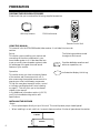
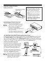
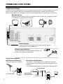
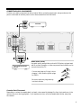
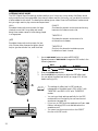
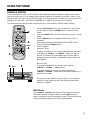
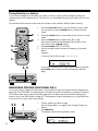
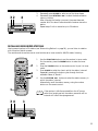
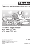
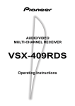
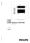
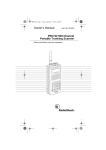
owner’s manual
Audio/Video Receiver
INTRODUCTION
The RCA STAV–3860 has these great features.
Five Channels of Independent Amplification — five independent power amplifiers, each rated at
60W, ensure accurate, dynamic reproduction of all multi-channel material.
Dolby* Pro Logic — enjoy stunning multi-channel, surround sound effects from movies and other
material recorded in Dolby Surround/Pro Logic. Enhance your listening experience further with built-in
signal processing that recreates the movie theater ambience in your living room.
Digital Surround Effects — using Digital Signal Processing (DSP) technology, various listening
environments, such as a theater or a jazz club, may be simulated and applied to any music or video
source.
DVD 5.1 Channel Input — a special 5.1 Channel input makes the STAV-3860 fully compatible with
Dolby Digital decoders and DVD players with 5.1 channel outputs.
The Energy-saving Design — this unit is designed to use minimal electricity when power is switched
OFF (in Standby mode). Regarding the value of the power consumption in standby mode, refer to
“Specifications” on pages 31.
Note to the Cable TV System Installer:
This reminder is provided to call the CATV system installer's attention to Article 820-40 of the
National Electrical Code that provides guidelines for proper grounding and, in particular,
specifies that the cable ground shall be connected to the grounding system of the building as
close to the point of cable entry as practical.
* Manufactured under license from Dolby Laboratories.
"Dolby", "Pro Logic" and the double-D symbol are trademarks of Dolby Laboratories.
Confidential unpublished works. © 1992-1997 Dolby Laboratories.All rights reserved.
©1999 Tandy Corporation.
All Rights Reserved.
2
IMPORTANT SAFETY INSTRUCTIONS
This receiver is made and tested to meet
exacting safety standards. It meets both
UL and FCC requirements and complies
with safety performance standards of the
US Department of Health and Human
Services.
Accessories — Do not place this product on an unstable cart, stand, tripod,
bracket, or table. The product may fall, causing serious injury to a child or adult,
and serious damage to the product. Use only with a cart, stand, tripod, bracket,
or table recommended by the manufacturer or sold with the product. Follow the
manufacturer’s instructions for mounting, and use a recommended mounting
accessory.
Carts — Move the product on a cart carefully. Quick
stops, excessive force, and uneven surfaces may cause the
product/cart to overturn.
WARNING:
TO REDUCE THE RISK OF
FIRE OR ELECTRIC SHOCK, DO NOT
EXPOSE THIS APPLIANCE TO RAIN OR
MOISTURE.
Ventilation — Slots and openings in the cabinet provide
ventilation, ensure reliable operation, and protect from
overheating. Do not block or cover these openings, and
do not place the product on a bed, sofa, rug, or other
similar surface. Do not place the product in a built-in
bookcase or rack unless it provides proper ventilation as
specified by the manufacturer.
CAUTION
RISK OF ELECTRIC SHOCK.
DO NOT OPEN.
CAUTION: TO REDUCE THE RISK OF
ELECTRIC SHOCK, DO NOT REMOVE
THE COVER. NO USER-SERVICEABLE
PARTS INSIDE. REFER SERVICING TO
QUALIFIED SERVICE PERSONNEL.
This symbol is intended to
alert you to the presence of
dangerous voltage inside
the product that can cause
shock. Do not open the
product’s case.
This symbol is intended to
alert you to important operating and maintenance instructions in this owner’s
manual.
Careful attention is devoted to quality standards in the
manufacture of your cassette deck, and safety is a major
factor in its design. However, safety is also your
responsibility.
This section lists important information that will help you
properly use and enjoy your cassette deck and accessories.
Read all the included safety and operating instructions
before using your cassette deck, follow them closely, and
retain them for future reference.
Heed Warnings — Follow all warnings on the product and
in the operating instructions.
Power Sources — Operate this product using only the power source indicated
on its marking label. If you are not sure of your home’s power type, consult your
product dealer or local power company.
Polarization — This product is equipped with a polarized AC line plug (a plug
having one blade wider than the other). This plug will fit in the power outlet
only one way. This is a safety feature. If you cannot insert the plug fully into the
outlet, try reversing the plug. If the plug still doesn’t fit, contact your electrician
to replace your obsolete outlet. Do not defeat the safety purpose of the polarized
plug. If you need an extension, use a polarized cord.
Power-Cord Protection — Route power-supply cords so they are not likely to
be walked on or pinched by items placed on or against them, paying particular
attention to cords at plugs, convenience receptacles, and the point where they
exit from the product.
Lightning — For added protection for this product during a lightning storm, or
when it is left unattended and unused for long periods of time, unplug it from
the wall outlet and disconnect the antenna or cable system. This will prevent
damage to the product due to lightning and power-line surges.
Overloading — Do not overload wall outlets, extension cords, or integral
convenience receptacles, as this can result in a risk of fire or electric shock.
Objects and Liquids — Never push objects of any kind into this product
through openings, as they may touch dangerous voltage points or short out parts
that could result in a fire or electric shock. Never spill liquid of any kind on the
product.
Servicing — Do not attempt to service this product yourself, as opening or
removing covers may expose you to dangerous voltage or other hazards. Refer all
servicing to qualified service personnel.
Damage Requiring Service — Unplug this product from the wall outlet and
refer servicing to qualified service personnel under the following conditions:
•
When the power-supply cord or plug is damaged.
•
If liquid has been spilled or objects have fallen into the product.
•
If the product has been exposed to rain or water.
•
If the product does not operate normally by following the operating
instructions. Adjust only those controls that are covered by the operating
instructions, as an improper adjustment of other controls may result in damage
and will often require extensive work by a qualified technician to restore the
product to normal operation.
•
If the product has been dropped or damaged in any way.
•
When the product exhibits a distinct change in performance.
Cleaning — Unplug this product from the wall outlet
before cleaning. Use only a damp cloth for cleaning. Do not
use liquid or aerosol cleaners.
Replacement Parts — When replacement parts are required, be sure the
service technician uses replacement parts specified by the manufacturer or
having the same characteristics as the original part. Unauthorized substitutions
may result in fire, electric shock, or other hazards.
Attachments — Do not use attachments/accessories not
recommended by the product manufacturer, as they might
create a hazard.
Safety Check — Upon completion of service or repairs to this product, ask the
service technician to perform safety checks to determine that the product is in
proper operating condition.
Water and Moisture — Do not use this product near
water (for example, near a bathtub, washbowl, kitchen sink,
or laundry tub; in a wet basement; or near a swimming
pool).
Wall or Ceiling Mount — The product should be mounted to a wall or ceiling
only as recommended by the manufacturer.
Heat — The product should be situated away from heat sources such as
radiators, heat registers, stoves, or other products (including amplifiers) that
produce heat.
3
Warning: This receiver uses a laser. Because of
possible eye injury, only a qualified service
person should remove the cover or attempt to
service this device.
Cautions
• The use of controls or adjustments, or the per
formance of procedures other than specified
herein, can result in hazardous exposure to
laser light.
• To prevent electric shock do not use this
polarized plug with an extension cord,
receptacle, or other outlet unless the blades
can be fully inserted to prevent blade
exposure.
4
TABLE OF CONTENTS
Preparation ....................................................................................................... 6
Checking the Supplied Accessories ............................................................................................. 6
Using this Manual ....................................................................................................................... 6
Installing the Receiver ................................................................................................................. 6
Preparing the Remote Control ..................................................................................................... 7
Connecting Your System .................................................................................... 8
Connecting Antennas .................................................................................................................. 8
Connecting Audio Components .................................................................................................. 9
Connecting DVD 5.1 Channel Components .............................................................................. 10
Connecting Video Components ................................................................................................ 10
Connecting Speakers ................................................................................................................. 11
AC Outlet ................................................................................................................................. 12
Setting Up for Surround Sound ....................................................................... 13
Setting Up for Surround Sound ................................................................................................. 13
Displays and Controls ..................................................................................... 17
Front Panel ............................................................................................................................... 17
Display ...................................................................................................................................... 18
Remote Control ......................................................................................................................... 19
Listening in Surround Sound .......................................................................... 20
Listening in Dolby Pro Logic Mode ........................................................................................... 20
Listening in DVD 5.1 Channel Input Mode ............................................................................... 21
Listening in DSP Mode .............................................................................................................. 22
Using the Tuner ............................................................................................... 23
Finding a Station ....................................................................................................................... 23
Tuning Directly to a Station ....................................................................................................... 24
Memorizing Stations ................................................................................................................. 24
Recalling Memorized Stations ................................................................................................... 25
Making a Recording......................................................................................... 26
Making an Audio or Video Recording ....................................................................................... 26
Additional System Control .............................................................................. 27
CD Player Controls ................................................................................................................... 27
Cassette Deck Controls ............................................................................................................. 28
Additional Information ................................................................................... 29
Troubleshooting ........................................................................................................................ 29
Specifications ............................................................................................................................ 31
5
PREPARATION
CHECKING THE SUPPLIED ACCESSORIES
Please check that you've received the following supplied accessories:
SOURCE
CD
TUNER
POWER
TAPE
$
$
ASMS
1
SOURCE SELECT
! SEARCH !
2
@
*
5
DECK2
3
4
&
#
6
7
0
@
EFFECT
9
8
DISC/STATION
#
D. ACCESS
CLASS
TUNING
DECK1
&
T.TONE
FM/AM
MPX
TUNING
AM Loop Antenna
FM Wire Antenna
SORROUND
CH SELECT
2
DSP MODE
MUTING
LEVEL
FL
RECEIVER FUNCTION DIMMER
VOLUME
POWER
STAV-3860
AUDIO/VIDEO SYSTEM REMOTE
OSR
Remote Control Unit
USING THIS MANUAL
This manual is for the STAV-3860 audio/video receiver. It is divided into two main
sections:
Set up
This section covers installing your receiver and
connecting all the other components in your
home theater system to it. It also describes how
to set up a multi-channel speaker system to take
full advantage of the great surround sound
features of your receiver.
Operation
This section shows you how to use every feature
of the receiver and its remote control unit. It
also covers using the supplied remote control to
operate your other home theater components.
To find out more about a specific button, control
or indicator, see Displays and Controls starting
on page 17. This will point you to the relevant
chapter in the manual.
In the Additional Information section (p.29–31)
you'll find a troubleshooting section and
specifications.
The following symbols are used
throughout this manual:
memo
Provides detailed precautions and
advice on operations, etc.
Indicates that display is blinking.
INSTALLING THE RECEIVER
Notes:
• Do not place objects directly on top of this unit. This would prevent proper heat dispersal.
• When installing in a rack, shelf, etc., be sure to leave more than 8 inches of space above the receiver.
8 INCHES
RECEIVER
6
PREPARING THE REMOTE CONTROL
CAUTION:
Incorrect use of batteries may result in
such hazards as leakage and bursting.
Observe the following precautions:
• Never use new and old batteries to
gether.
• Insert the plus and minus sides of
the batteries properly according to
the marks in the battery case.
• Batteries with the same shape may
have different voltages. Do not use
different batteries together.
Loading the batteries
Dry Cell Batteries (not included)
(AA size IEC R6P x 2)
30
30
1
4
2
5
3
6
+
+
-
Operating Range of Remote Control Unit
The remote control may not work properly if:
memo • There are obstacles between the remote
control and the receiver's remote sensor.
• Direct sunlight or fluorescent light is
shining onto the remote sensor.
• The receiver is located near a device that is
emitting infrared rays.
• The receiver is operated simultaneously
with another infrared remote control unit.
23 ft.
The FUNCTION & SOURCE SELECT Buttons on the Remote Control
Please note that the remote control has two types of buttons, one called FUNCTION and a set of buttons
called SOURCE SELECT. Use the FUNCTION button to choose the component you want to listen to
(CD, CDR/TAPE, TUNER, etc.) and use the SOURCE SELECT buttons to change which component the
remote control itself will operate. Thus, if the STAV-3860 is in TUNER mode, for example, and you want
to listen to your CD player, you need to select the CD mode with the FUNCTION button.
Operating other RCA Components
CONTROL
By connecting a control cord (optional), you can
control other RCA professional series equipment
using this remote control unit. Point the remote
control unit towards the remote sensor of this
unit, even when operating other equipment.
CONTROL
OUT
IN
OUT
STAV-3860
The remote control signals are received by the
remote sensor of this unit, and sent to the other
devices via the CONTROL OUT terminal.
memo
You can also control RCA professional
series components by pointing the
receiver's remote control directly at the
component. This type of operation
does not require control cords.
OTHER RCA PROFESSIONAL
SERIES PRODUCTS WITH OSR
MARK
REMOTE CONTROL UNIT
CONNECT TO CONTROL IN
TERMINAL OF OTHER RCA
PROFESSIONAL SERIES
PRODUCTS WITH OSR MARK.
7
CONNECTING YOUR SYSTEM
CONNECTING ANTENNAS
Connect the AM loop antenna and the FM wire antenna as shown below. To improve reception and sound
quality, connect external antennas (see Using external antennas, below). Always make sure that the
receiver is switched off and unplugged from the wall outlet before making or changing any connections.
AM Loop Antenna
Assemble the antenna and connect to the receiver. Attach to a wall, etc. (if desired) and face
in the direction that gives the best reception.
R
AM LOOP
ANTENNA
IN
L
CD
CONTROL
O
U
T
OUT
VCR/
DVR
IN
FM
UNBAL
75Ω
FM
ANTENNA
IN
OUT
IN
TV/
SAT
IN
TO
MONITOR
TV
IN
DVD
/LD IN
FRONT
SUB
WOOFER
PREOUT
R
E
C
P
L
A
Y
OUT
CD-R
/TAPE
/MD
FRONT
SPEAKERS
R
CENTER
SPEAKER
L
SURROUND
SPEAKERS
R
AC OUTLET
L
SURROUND
R
L
CENTER
IN
SUB
WOOFER
DVD 5.1 CH
INPUT
FM Wire Antenna
Connect the FM wire antenna and fully extend vertically along a
window frame or other suitable area.
Antenna Snap Connectors
Twist the exposed wire strands together and insert into
the hole, then snap the connector shut.
3/8 In.
Using External Antennas
7 To Improve FM Reception
Connect an external FM antenna.
7 To Improve AM Reception
Connect a 15–18 feet length of vinyl-coated wire to the AM
antenna terminal without disconnecting the supplied AM loop
antenna.
For the best possible reception, suspend horizontally outdoors.
OUTDOOR ANTENNA
75 Ω COAXIAL CABLE
FM
UNBAL
75Ω
FM
ANTENNA
AM LOOP
ANTENNA
INDOOR ANTENNA
(VINYL-COATED WIRE)
15–18 FT
8
CONNECTING AUDIO COMPONENTS
Connect your audio components as shown below. When connecting equipment, always make sure the
power is switched off and the power cord is disconnected from the wall outlet.
OUT
L
CD PLAYER
R
R
AM LOOP
ANTENNA
IN
L
CD
CONTROL
O
U
T
OUT
VCR/
DVR
IN
FM
UNBAL
75Ω
FM
ANTENNA
IN
IN
TV/
SAT
IN
TO
MONITOR
TV
IN
DVD
/LD IN
FRONT
SUB
WOOFER
PREOUT
R
E
C
P
L
A
Y
OUT
CD-R
/TAPE
/MD
FRONT
SPEAKERS
R
CENTER
SPEAKER
L
SURROUND
SPEAKERS
R
AC OUTLET
L
SURROUND
R
L
CENTER
IN
SUB
WOOFER
PLAY
DVD 5.1 CH
INPUT
REC
L
R
CD-R, CASSETTE DECK MD,
DAT ETC.
Audio/Video Cords
Use good quality audio/video cords with RCA/phono plugs at each
end to connect the audio or video components and a video cord to
connect the monitor/TV.
VI
DE
IN O
Connect red plugs to R (right), white
plugs to L (left), and the yellow plugs
to VIDEO.
L
R
Be sure to push the plugs securely
into their sockets.
Cassette Deck Placement
Depending on where the cassette deck is placed, noise caused by leakage flux from the transformer in the
receiver may occur during playback. If you experience noise, move the cassette deck farther away from
the receiver.
9
CONNECTING DVD 5.1 CHANNEL COMPONENTS
DVD and LD discs are compatible with both 2 channel and 5.1 channel audio output formats. Refer to
page 21 for more information on how to switch between the two input methods. You can connect a DVD
player or multi channel decoder equipped with 5.1 analog outputs to the 5.1 analog inputs on the
receiver. Always make sure that the receiver is switched off and unplugged from the wall outlet before
making or changing any connections.
R
AM LOOP
ANTENNA
L
IN
CD
CONTROL
O
U
T
OUT
VCR/
DVR
IN
FM
UNBAL
75Ω
FM
ANTENNA
IN
IN
TV/
SAT
IN
TO
MONITOR
TV
IN
DVD
/LD IN
FRONT
SUB
WOOFER
PREOUT
R
E
C
OUT
CD-R
/TAPE
/MD
P
L
A
Y
FRONT
SPEAKERS
R
CENTER
SPEAKER
SURROUND
SPEAKERS
L
R
AC OUTLET
L
SURROUND
R
L
CENTER
IN
SUB
WOOFER
FRONT
OUT PUT
DVD 5.1 CH
INPUT
SURROUND
OUT PUT
L
L
R
R
SUB
WOOFER
CENTER
VIDEO
OUT
COMPONENTS EQUIPPED WITH
5.1 CHANNEL ANALOG OUTPUT
JACKS
memo
The 5.1 channel input can only be used when
DVD 5.1 CH is selected.
CONNECTING VIDEO COMPONENTS
Connect your video components as shown below. When connecting equipment, make sure the power is
switched off and the power cord disconnected from the wall outlet.
VCR, DVR, ETC.
OUT
TV MONITOR
IN
IN
V
VIDEO
L
R
R
AM LOOP
ANTENNA
L
IN
CD
CONTROL
O
U
T
OUT
VCR/
DVR
IN
FM
UNBAL
75Ω
FM
ANTENNA
IN
IN
TV/
SAT
IN
DVD
/LD IN
FRONT
R
E
C
P
L
A
Y
OUT
CD-R
/TAPE
/MD
OUT
TO
MONITOR
TV
IN
FRONT
SPEAKERS
R
SURROUND
R
L
CENTER
IN
SUB
WOOFER
DVD 5.1 CH
INPUT
OUT
V
L
R
10
DVD/LD PLAYER
CENTER
SPEAKER
L
SURROUND
SPEAKERS
R
L
AC OUTLET
CONNECTING SPEAKERS
Connect your speakers as shown below. Be sure to connect each speaker to the appropriate speaker
terminals, and also to connect the positive and negative terminals correctly (positive to positive, negative
to negative). When connecting equipment, always make sure the power switched off and the power cord
is disconnected from the wall outlet.
• Use speakers with a nominal impedance of 8 Ω to 16 Ω.
FRONT
(LEFT)
POWERED SUB-WOOFER
FRONT
(RIGHT)
CENTER
INPUT
R
AM LOOP
ANTENNA
IN
L
CD
CONTROL
O
U
T
OUT
VCR/
DVR
IN
FM
UNBAL
75Ω
FM
ANTENNA
IN
OUT
IN
TV/
SAT
IN
TO
MONITOR
TV
IN
DVD
/LD IN
FRONT
SUB
WOOFER
PREOUT
R
E
C
P
L
A
Y
OUT
CD-R
/TAPE
/MD
FRONT
SPEAKERS
R
CENTER
SPEAKER
L
SURROUND
SPEAKERS
R
AC OUTLET
L
SURROUND
R
L
CENTER
IN
SUB
WOOFER
DVD 5.1 CH
INPUT
SURROUND
(LEFT)
Speaker terminals
Use good quality speaker wire to connect the speakers to the
receiver.
1 Twist about 1/2 inch of bare wire strands together.
2 Unclip the speaker terminal and insert the wire.
3 Snap shut the speaker terminal to secure.
SURROUND
(RIGHT)
ª
·
11
Hints on Speaker Placement
Speakers are usually designed with a particular placement in mind. Some are designed to be
floorstanding, while others should be placed on stands to sound their best. Some should be placed near a
wall; others should be placed away from walls. Follow the guidelines on placement that the speaker
manufacturer provided with your particular speakers.
• Place the front left and right speakers at equal
distances from the TV.
• When placing speakers near the TV, we
recommend using magnetically shielded
speakers to prevent possible interference,
such as discoloration of the picture when the
TV is switched on. If you do not have
magnetically shielded speakers and notice
discoloration of the TV picture, move the
speakers farther away from the TV.
• Install the center speaker above or below the
TV so that the sound of the center channel is
localized at the TV screen.
CAUTION: If you choose to install the
center speaker on top of the TV, be sure to
secure it with putty, or by other suitable
means, to reduce the risk of damage or
injury resulting from the speaker falling
from the TV in the event of external shocks
such as earthquakes.
To achieve the best possible surround sound,
install your speakers as shown below. Be sure all
speakers are installed securely to prevent
accidents and improve sound quality.
FRONT
LEFT
CENTER
FRONT
RIGHT
SUB WOOFER
SURROUND LEFT
SURROUND RIGHT
LISTENING
POSITION
3-D View of Speaker Set Up
• If possible, install the surround speakers
slightly above ear level.
• Try not to install the surround speakers
farther away from the listening position than
the front and center speakers. Doing so can
weaken the surround sound effect.
AC OUTLET [SWITCHED 100 W (0.8 A) MAX]
Power supplied through this outlet is turned on and off by the receiver's STANDBY/ON button.
Total electrical power consumption of connected equipment should not exceed 100 W (0.8 A).
Do not connect a heater, TV, etc.
memo
• This unit should be disconnnected by removing the power plug
from the wall socket when not in regular use.
• Do not connect appliances with high power consumption such as
heaters, irons, or television sets to this AC OUTLET in order to
avoid overheating and fire risk. This can also cause the receiver to
malfunction.
CAUTION: DO NOT CONNECT A MONITOR OR TV SET TO THIS UNIT'S AC
OUTLET.
12
SETTING UP FOR SURROUND SOUND
SETTING UP FOR SURROUND SOUND
The STAV-3860 offers several options for surround sound listening, depending on the speakers in your set
up. Having installed the speakers in your room, it's important to set up the relative volume levels and
delay time in order to make the most of the receiver's surround sound capabilities. You only need to make
these settings once, unless you change the placement of your current speaker system or add new
speakers.
Setting the Center Mode, the Subwoofer and Speaker Distances
It is important to set the type of center mode which corresponds to your speaker system, set the
subwoofer on/off, set speaker distances, and set volume levels of each speaker. From your normal
listening position, the volumes of the various speakers in your system should appear to be equal. Follow
the steps below for settings, especially the volumes of the center and surround speakers relative to the
main front speakers for Dolby Pro Logic mode, 5.1 CH. mode and the DSP mode.
1
2
3
SOURCE
CD
TUNER
POWER
TAPE
$ ASMS $
1
SOURCE SELECT
!
2
@
*
5
DECK 2
6
!
4
&
#
7
8
EFFECT
9
SEARCH
3
DISC/STATION
@
0
D. ACCESS
#
CLASS
TUNING
DECK 1
&
T.TONE
FM/AM
MPX
TUNING
2
1
SORROUND
CH SELECT
2
DSP MODE
MUTING
CHANNEL
LEVEL
FL
RECEIVER FUNCTION DIMMER
VOLUME
POWER
STAV-3860
AUDIO/VIDEO SYSTEM REMOTE OSR
4
4
3
4
Switch on the receiver.
Press the SURROUND button.
Press the 3 button to select the surround sound setup mode.
Repeatedly pressing the button cycles through the three setup
modes (center mode setup; subwoofer setup; distance setup).
The mode appears in the display on the front panel.
Use the 5∞ buttons to select one of the four types of center
mode.
The center mode cycle and the diagrams below explain each
center mode.
3 NORMAL 2
3 WIDE 2
3 3 STEREO 2
3 PHANTOM 2
Normal
Middle and high frequency sounds are heard
from the center speaker.
Bass frequencies from the center channel are
played through the front speakers.
Wide
If a full range speaker is used for the center
channel, all center channel sound, including
bass frequencies, are heard through the
center speaker.
1
Phantom
Center channel sounds are played through
both front speakers equally.
3 Stereo
Surround channel sounds and center channel
bass frequencies are heard through the front
stereo speakers.
13
Press the 3 button to select the SUBWF (subwoofer) select mode.
Use the 5∞ buttons to turn the subwoofer function on or off.
Select SUBWF ON if you have a subwoofer and SUBWF OFF
if you don't have a subwoofer.
7 Press the 3 button to select the distance mode for the FRNT
(front) speakers.
For true surround sound effect, the sound from the front
speakers and the surround speakers should arrive to the
listener's ears at a slightly different time. Telling the receiver
how far your front and surround speakers are from your
listening position will allow for this. The first distance setting
you'll see will be FRNT for your front speakers. You can set the
distance in a range from 1–30 feet.
8 Press the 5∞ buttons to increase/decrease the distance of the
FRNT speakers.
You should determine how far the speakers are from your
normal listening position and set the distance accordingly. You
can set the distance in a range from 1–30 feet.
9 Press the 3 button to select the distance mode for the SURR
(surround) speakers.
10 Press the 5∞ buttons to increase/decrease the distance of the
SURR speakers.
5
6
SOURCE
CD
TUNER
POWER
TAPE
$ ASMS $
1
SOURCE SELECT
!
2
@
*
5
DECK 2
!
4
&
#
6
7
0
@
EFFECT
9
SEARCH
3
8
DISC/STATION
D. ACCESS
#
CLASS
TUNING
DECK 1
&
T.TONE
FM/AM
MPX
TUNING
SORROUND
CH SELECT
2
DSP MODE
MUTING
CHANNEL
LEVEL
FL
RECEIVER FUNCTION DIMMER
VOLUME
POWER
STAV-3860
AUDIO/VIDEO SYSTEM REMOTE OSR
6, 8, 10
5, 7, 9
6, 8, 10
Again, determine how far the speakers are from your normal
listening position and set the distance accordingly. As above,
you can set the distance in a range from 1–30 feet.
When you are finished setting up the delay time, the receiver
will return to normal operating mode after about 20 seconds.
Alternatively, you can cycle through the options with the 2 3
buttons until you return to the regular operating mode.
memo
14
You only need to make the distance settings if your system
has surround speakers.
SETTING UP SPEAKER LEVELS FOR DOLBY PRO LOGIC
For the best surround sound, set up the relative speaker levels so that they all have the same volume from
your normal listening position. Follow the steps:
SOURCE
CD
1
2
3
TUNER
POWER
TAPE
SOURCE SELECT
$ ASMS $
1
!
2
@
*
5
DECK 2
6
&
#
7
8
4
DISC/STATION
@
0
#
D. ACCESS
3, 5
!
4
EFFECT
9
SEARCH
3
CLASS
TUNING
DECK 1
&
T.TONE
FM/AM
MPX
TUNING
2
1
2
SORROUND
DSP MODE
5
MUTING
CHANNEL
LEVEL
CH SELECT
FL
RECEIVER FUNCTION DIMMER
VOLUME
4
Press the 2 button.
Press the SURROUND button.
Press the T.TONE button.
A short test tone will be heard in turn from each speaker in
your set up, except the subwoofer.
Adjust the respective speaker levels with the
CHANNEL LEVEL +/– buttons when the TEST TONE sounds
from that speaker.
Adjust the volumes of the speakers so that the volume of all
speakers appears equal from your normal listening position.
Press T.TONE again.
When you are satisfied that the set up is complete, press the
T.TONE button to return to normal operation.
POWER
STAV-3860
AUDIO/VIDEO SYSTEM REMOTE OSR
memo
• No TEST TONE sounds for the subwoofer
• These speaker level settings are applicable to
PRO LOGIC, PRO LOGIC with THEATER 1 & PRO
LOGIC with THEATER 2 settings.
SETTING UP SPEAKER LEVELS FOR DVD 5.1 CH
1
2
3
SOURCE
CD
TUNER
POWER
TAPE
$ ASMS $
1
SOURCE SELECT
!
2
@
*
5
DECK 2
6
&
#
7
4
!
4
EFFECT
9
SEARCH
3
8
DISC/STATION
@
0
D. ACCESS
#
CLASS
5
TUNING
DECK 1
&
T.TONE
FM/AM
MPX
TUNING
SORROUND
3, 5,
7
1
CH SELECT
2
DSP MODE
MUTING
CHANNEL
LEVEL
FL
RECEIVER FUNCTION DIMMER
VOLUME
POWER
STAV-3860
AUDIO/VIDEO SYSTEM REMOTE OSR
4, 6,
7
2
6
7
Use the FUNCTION button to select DVD 5.1 CH input mode.
Play a DVD 5.1 CH source and set the master volume to a
moderate level.
Press the CH SELECT button.
The first speaker, FL (front left), and its relative volume level
(+/– **dB) appears in the display.
Adjust the front left (FL) speaker level with the
CHANNEL LEVEL +/– buttons.
Adjust the volumes of the speakers to a standard level of your
choice when seated in your normal listening position.
Press CH SELECT again to move to the next speaker.
The second speaker CT (center) and its relative volume level
(+/– **dB) appears in the display.
Adjust the center (CT) speaker level with the
CHANNEL LEVEL +/– buttons.
Adjust the speaker volume so it seems the same as the previous
speaker from your normal listening position.
Repeat steps 3 & 4 for all of your speakers.
Adjust the volumes of the all speakers so their volume seems
the same from your normal listening position.
15
SETTING UP SPEAKER LEVELS FOR DSP
1
2
SOURCE
CD
TUNER
3
POWER
TAPE
$ ASMS $
1
2
@
*
5
SOURCE SELECT
!
DECK 2
!
4
#
6
7
0
@
EFFECT
9
SEARCH
3
&
8
4
DISC/STATION
D. ACCESS
#
CLASS
TUNING
DECK 1
&
T.TONE
FM/AM
MPX
TUNING
SORROUND
3, 5,
7
CH SELECT
2
DSP MODE
CHANNEL
LEVEL
FL
RECEIVER FUNCTION DIMMER
1
5
MUTING
VOLUME
POWER
STAV-3860
AUDIO/VIDEO SYSTEM REMOTE OSR
4, 6,
7 6
2
7
Use the DSP MODE button to turn on a DSP effect.
You can cycle through the five different types with the DSP
button.
Play a source (CD, tape,etc.) and set the master volume to a
moderate level.
Press the CH SELECT button.
The first speaker FL (front left) and it's relative volume level
(+/- **dB) appears in the display.
Adjust the front left (FL) speaker level with the
CHANNEL LEVEL +/– buttons.
Adjust the volumes of the speakers to a standard level of your
choice when seated in your normal listening position.
Press CH SELECT again to move to the next speaker.
The second speaker CT (center) and it's relative volume level
(+/-**dB) appears in the display.
Adjust the center (CT) speaker level with the
CHANNEL LEVEL +/– buttons.
Adjust the volume of the speaker so its volume seems the same
as the previous speaker from your normal listening position.
Repeat steps 3 & 4 for all of your speakers.
Adjust the volumes of all the speakers so their volume seems
the same from your normal listening position.
memo
16
• These speaker level settings are applicable to DSP
effects only.
• Each effect level applies only to the DSP type (HALL
for example) that it is set in. You can set the effect
levels for each type independently.
DISPLAYS AND CONTROLS
FRONT PANEL
7
1 2 3 4 56
8 9 0
DOLBY SURROUND
P R O • L O G I C
2
3
2
3
OSR
2
=
~
!
1 POWER button
Switches the receiver between on and standby.
2 STANDBY indicator
Lights when the receiver is in standby mode (note
that the receiver consumes a small amount of
power (1W) in standby mode).
3 STATION 2 3 (–/+), FREQUENCY 2 3
(–/+), TUNING SELECT buttons
STATION 2 3 (–/+)
Selects station memories when using the tuner.
FREQUENCY 2 3 (–/+)
Selects the frequency when using the tuner.
TUNING SELECT
Switches between station memory and frequency
select modes (see pages 23–25).
4 CLASS button
Switches between the three banks (classes) of
station memories (see page 25).
5 MEMORY button
Press to memorize a station for recall using the
STATION 2 3 buttons (see page 24).
6 MPX MODE button
lf the TUNED or STEREO indicators don't light
when tuning to an FM station because the signal
is weak, press the MPX button to switch the
receiver into mono reception mode. This should
improve the sound quality and allow you to enjoy
the broadcast (see page 23).
7 Display (see page 18)
8 Remote sensor
Receives the signals from the remote control.
9 DSP MODE button
Use to switch between the various DSP modes
available (HALL, JAZZ, DANCE, THEATER 1,
THEATER 2) and DSP off. Use to create different
surround sound effects from any stereo source
(see page 22).
3
@
2
3
# $
%
^
0 DOLBY PRO LOGIC button
Use to switch between the various Pro Logic
modes (PRO LOGIC, PRO LOGIC with
THEATER 1, PRO LOGIC with THEATER 2) and
Pro Logic off (see page 20).
- VOLUME
Use to set the overall listening volume.
= PHONES jack
Use to connect headphones but this does not
switch the speakers off.
~ SPEAKERS ON/OFF button
Use to switch the speaker system on or off.
! FL DIMMER button
Use this button to make the fluorescent display
(FL) dimmer or brighter. There are three
brightness settings as well as an off setting.
@ BASS 2 3 (–/+) buttons
Use to increase/decrease bass (within a range of
–6dB to 6dB in 2dB steps). It cannot be used
when S.BASS is on.
# TREBLE2 3 (–/+) buttons
Use to increase/decrease treble (within a range of
–6dB to 6dB in 2dB steps).
$ Function buttons
Use to select a source for playback or recording.
% S.BASS button
Use to switch on and off the bass boost. Use for a
more powerful bass sound. Negates use of BASS
buttons.
^ DIRECT button
Use to switch DIRECT playback on or off. This
mode bypasses the tone controls and channel
levels for the most accurate reproduction of a
program source.
17
DISPLAY
1
2
PRO LOGIC
DSP
3
DIRECT
4
5
MONITOR MONO
S. BASS SP
A
TUNED
STEREO
dB
9
1 2 PRO LOGIC indicator
Lights when any Dolby Pro Logic mode is
selected.
The main character display briefly shows the
current Pro Logic mode (PRO LOGIC,
THEATER 1, THEATER 2) after selection (see
page 20).
2 DSP indicator
Lights when any DSP mode is selected. The main
character display briefly shows the current DSP
mode (HALL, JAZZ, DANCE, THEATER1 and
THEATER 2) after selection (see page 22).
3 DIRECT indicator
Lights when source DIRECT is on. This function
bypasses all tone, balance, DSP and Dolby
Surround effects.
4 MONITOR indicator
Lights when MONITOR is selected to hear a
recording as it's being made (see page 26).
5 TUNER indicators
MONO:
Lights when the mono mode is set using the
MPX MODE button (see page 23).
TUNED:
Lights when a broadcast is being received.
STEREO:
Lights when a stereo FM broadcast is being
received in auto stereo mode.
18
8
7
6
6 MASTER VOLUME LEVEL
Shows the overall volume level. Volume level is
maintained even when the power is off. ---dB
indicates the minimum level, and 0dB indicates
the maximum level.
•
Depending on the level settings for
individual channels, the MAX level can
range between –10dB and 0dB.
7 SPEAKER indicator
Shows if the speaker system is on or not. If SP
3A appears, speakers are switched on.
If SP 3 appears, speakers are switched off.
8 S. BASS indicator
Lights when the S. BASS is on (see note %
on page 17).
9 CHARACTER display
Shows the radio frequency or function (DVD/LD,
CD, etc.) receiver is using .
7 CH SELECT button
REMOTE CONTROL
Used to start the process of setting the speaker
levels (see $ below) (see pages 15–16).
8 RECEIVER STANDBY/ON button
1
SOURCE
CD
POWER
TAPE
2
$
$
ASMS
1
*
5
DECK2
3
4
&
#
7
8
6
DISC/STATION
@
0
#
D. ACCESS
CLASS
TUNING
DECK1
&
4
5
6
7
8
9
T.TONE
FM/AM
MPX
TUNING
SORROUND
CH SELECT
2
DSP MODE
MUTING
LEVEL
FL
RECEIVER FUNCTION DIMMER
=
~
!
@
#
$
VOLUME
OSR
9 FUNCTION button
0 SOURCE SELECT keys
POWER
STAV-3860
AUDIO/VIDEO SYSTEM REMOTE
Use to switch the receiver between on and
standby modes.
Use select the playback or recording source.
! SEARCH !
EFFECT
9
0
SOURCE SELECT
2
@
3
TUNER
%
^
1 SOURCE (POWER) button
2 NUMBER/PLAYER COMMAND buttons
Use to select the radio frequency in tuner mode.
Also, you can use to contol RCA professional
series components like CD players, cassette decks,
etc. according to the comands printed above the
button (4, 3, 7, etc.) (see pages 24, 27–29).
3 D.ACCESS button
This button gives you direct access to radio
frequency input, allowing you to input a station
directly. In DVD mode this button brings you to
the top menu (see pages 24, 29).
4 T.TONE / FM/AM button
Use this button to hear a test tone from each
speaker in turn to set the relative speaker
volumes. Also switches the BAND in TUNER
mode (see pages 15, 23–24).
5 SURROUND button
Use this button to set up the surround sound
features of the STAV-3860. Use it to select the
type of center mode, turn on/off subwoofer
option and select delay time for each speaker, or
to start the process of setting the effect levels
(see pages 13, 15, 20, 22).
6 2 button
Use to select a Dolby Pro Logic mode. Also used
to access Test Tone (see pages 15, 20).
Use to put the remote control (NOT the receiver)
in the stated mode.
For other equipment controls, see Controlling the
Rest of Your System starting on page 27.
- DISC/STATION +/– buttons
Use to select the station of memorized
frequencies (see pages 25, 27).
= CLASS button
Use to switch between the three banks (classes) of
station memories (see page 25).
~ 2 3 5∞ ( TUNING +/–) and
7(ENTER)buttons
Use these arrow buttons when setting up your
surround sound system (see pages 13–16). These
buttons are also used to control for deck 1 of a
double cassette deck player. The TUNING +/–
buttons can be used to find radio frequencies
(see pages 13, 14, 23).
! MPX button
Use to switch between auto stereo and mono
reception of FM broadcasts. If the signal is weak
then switching to MONO will improve the sound
quality (see page 23).
@ DSP MODE button
Use to switch between the various DSP modes
available (HALL, JAZZ, DANCE, THEATER 1,
THEATER 2) and DSP off. Use to create different
surround sound effects from any stereo source
(see page 22).
# MUTING button
Use to mute all audio without affecting any of the
current sound settings.
$ CHANNEL LEVEL+/– buttons
Use to set the relative speaker volumes for all the
speakers in your system (see 7 above) (see pages
15, 16).
% VOLUME +/– buttons
Use to set the overall listening volume.
^ FL DIMMER button
Use this button to make the fluorescent display
(FL) dimmer or brighter. There are three
brightness settings as well as an off setting.
19
LISTENING IN SURROUND SOUND
LISTENING IN DOLBY PRO LOGIC MODE
To really appreciate what the STAV-3860 can do, sit back and experience a movie encoded in Dolby
Digital or Dolby Surround with five speaker surround sound creating theater-like sound effects in your
mark on DVD discs, laser discs, and
living room. When choosing software, look for the
video tapes (sometimes, unmarked software is also recorded in Dolby Surround).
To enjoy Dolby Digital surround sound from DVD discs, you'll need to have connected your DVD player
(or Dolby Digital decoder) to the receiver's 5.1 channel inputs (see page 10), and set the receiver to DVD
5.1CH input mode. See "Listening in DVD 5.1 Channel Imput Mode" on page 21.
Many video tapes feature Dolby Surround/Pro Logic. The STAV-3860 takes advantage of this to provide
dramatic and realistic surround sound. The effect can be further enhanced by choosing a Pro Logic with
DSP mode. Follow the steps on this page when playing Dolby Surround or Dolby Pro Logic material.
When using any of these modes, it's really important that your speakers are set up correctly (see pages
11–12), and that you've worked through the steps in Setting Up for Surround Sound on pages 13–15.
1
SOURCE
CD
Press the2 button(DOLBY PRO LOGIC on the receiver).
Pressing repeatedly changes the Pro Logic mode in the
following sequence:
3 DOLBY PRO
TUNER
POWER
TAPE
$ ASMS $
1
3
2
@
*
5
6
DECK 2
SEARCH
3
4
#
7
8
SURR OFF 2
DISC/STATION
@
0
D. ACCESS
#
2
DECK 1
&
T.TONE
FM/AM
MPX
TUNING
2
1
CH SELECT
2
DSP MODE
MUTING
CHANNEL
LEVEL
FL
RECEIVER FUNCTION DIMMER
VOLUME
POWER
STAV-3860
AUDIO/VIDEO SYSTEM REMOTE OSR
3
Press the SURROUND button.
This starts the process of setting the effect level.
Use the EFFECT +/– to adjust the DSP effect level PRO LOGIC
with THEATER 1 and PRO LOGIC with THEATER 2.
You can adjust the effect level within an range of 10–90 (the
default settinig is 50).
memo
1
20
PRO LOGIC
2
with
THEATER 2
CLASS
TUNING
SORROUND
THEATER 1
!
&
EFFECT
9
LOGIC
SOURCE SELECT
!
PRO LOGIC
3 with
• You need to input mode/distance/level settings
specifically for your Pro Logic mode (see pages 13–
15).
• If you turn the speakers off PRO LOGIC goes off as
well. When you turn the speakers back on, PRO
LOGIC will NOT go back on.
• If you try and turn PRO LOGIC on when the speakes
are off, SP OFF will flash on the display, informing
you that you can't turn on PRO LOGIC when the
speakers are off.
• You can't use the tone controls, or the DIRECT
function with PRO LOGIC mode.
LISTENING IN DVD 5.1 CHANNEL INPUT MODE
You can use this feature if you have a DVD player and a Dolby Digital decoder or a DVD player with a
built-in Dolby Digital decoder. Both these decoders will have separate analog audio outputs for the front
left and right, center, surround left and right, and sub-woofer channels. Connect these to the 5.1 channel
inputs of the STAV-3860 for enhanced playback of Dolby Digital material—see page 10 for instructions
on connecting. 5.1 channel mode of the STAV-3860 provides better surround-channel sound and overall
channel separation than the Dolby Pro Logic mode.
Follow the steps below to use the 5.1 channel mode.
1
SOURCE
CD
TUNER
POWER
TAPE
$ ASMS $
1
2
@
*
5
SOURCE SELECT
!
DECK 2
!
4
#
6
7
0
@
EFFECT
9
SEARCH
3
&
Use the FUNCTION button to select DVD 5.1 CH.
On the receiver, press the DVD 5.1 CH function button to select
the DVD input mode directly.
On the remote control, repeated presses of the FUNCTION
button switches between 5.1 channel input and the other
inputs.
8
DISC/STATION
D. ACCESS
#
CLASS
TUNING
memo
DECK 1
&
T.TONE
FM/AM
MPX
TUNING
SORROUND
CH SELECT
2
DSP MODE
MUTING
CHANNEL
LEVEL
FL
RECEIVER FUNCTION DIMMER
VOLUME
POWER
1
STAV-3860
AUDIO/VIDEO SYSTEM REMOTE OSR
• You can input level settings spefically for the 5.1 CH
mode to enhance you surround sound experience
(see "Setting Up Speaker Levels for DVD 5.1CH" on
page 15).
• The tone controls, S.BASS, or the DIRECT function are
not available in 5.1 CH mode.
1
21
LISTENING IN DSP MODE
The DSP (Digital Signal Processing) modes transform your living room into a variety of different sound
environments when playing standard (two channel) stereo sources. Optionally, you can adjust the amount
of effect added to the source. The descriptions below give an idea of how the five different modes sound,
but you might want to play a source and experiment.
HALL
Simulates the acoustic environment of a large
classical concert hall. Long delay and reverb
decay times create a sense of music being played
in a large space.
JAZZ
Simulates the acoustic environment of a jazz
club. Shorter delay times and a tighter reverb
help to give the sound a live, small club feel.
1
SOURCE
CD
TAPE
$
3
1
2
@
*
5
!
SEARCH
3 HALL
DSP
2
OFF
!
3
4
&
#
6
7
8
0
@
EFFECT
9
2
3
DISC/STATION
D. ACCESS
#
CLASS
TUNING
DECK 1
&
T.TONE
FM/AM
MPX
TUNING
2
SORROUND
CH SELECT
2
DSP MODE
3 JAZZ
THEATER 2 2
3 DANCE
THEATER 1 2
Press the SURROUND button.
Use the EFFECT +/– buttons to adjust the DSP effect level.
You can adjust the effect level within an range of 10–90 (the
default settinig is 50).
MUTING
CHANNEL
LEVEL
FL
RECEIVER FUNCTION DIMMER
VOLUME
1
POWER
STAV-3860
AUDIO/VIDEO SYSTEM REMOTE OSR
1
22
THEATER 2
Similar to the above but maintains proper
localization of each channel.
TUNER
SOURCE SELECT
DECK 2
THEATER 1
Simulates the acoustic environment of a
mid-sized movie theater.
Use to DSP MODE button to select a DSP MODE.
Repeated presses of DSP MODE changes the DSP mode in the
following sequence:
POWER
ASMS $
DANCE
Simulates the acoustic environment and strong
bass sound of a dance music club.
memo
• The settings for effect level in DSP mode are
independent of the effect level in PRO LOGIC with
THEATER 1 and PRO LOGIC with THEATER 2
modes.
• You can input level settings spefically for the DSP
mode and this will enhance your surround sound
experience (see page 16).
• If you turn on DSP when the speakes are off, SP OFF
flashes, indicating DSP is not available when the
speakers are off.
• You cannot use the tone controls or the DIRECT
function with DSP mode.
USING THE TUNER
FINDING A STATION
Follow steps below to tune in to FM and AM radio broadcasts using the automatic (search) and manual
(step) tuning functions. If you already know the exact frequency of the station you want to listen to, see
Tuning Directly to a Station on the following page. Once you are tuned to a station you can memorize the
frequency for recall later—see "Memorizing Stations" on page 24 for more on how to do this.
The receiver and the remote control must both be set to tuner mode for AM/FM station listening.
1
SOURCE
CD
TUNER
POWER
TAPE
$ ASMS $
1
!
2
@
*
5
DECK 2
6
SEARCH
4
&
#
7
@
0
#
CLASS
TUNING
DECK 1
&
T.TONE
FM/AM
MPX
2
DSP MODE
MUTING
CHANNEL
LEVEL
FL
RECEIVER FUNCTION DIMMER
VOLUME
POWER
4
4
MPX
TUNING
SORROUND
CH SELECT
1
3
8
DISC/STATION
D. ACCESS
3
2
!
3
EFFECT
9
2
SOURCE SELECT
STAV-3860
AUDIO/VIDEO SYSTEM REMOTE OSR
MPX
1
4
4
Use the FUNCTION button to put the receiver in tuner mode.
On the receiver, press the FM/AM button to select the tuner
mode.
Press the TUNER button on the remote control to put it in tuner
mode.
Use the FM/AM button to change the band (FM or AM), if
necessary.
Each press switches the band between FM and AM (on the
front panel use the FM/AM button).
Tune to a station.
Automatic Tuning
To search for stations in the currently selected band, press and
hold either the TUNING. + or TUNING. – button for about a
second. The receiver will start searching for the next station,
stopping when it has found one. Repeat this step to search for
other stations.
Manual Tuning
To change the frequency one step at a time, press the
TUNING. + / TUNING. – (5∞) buttons.
To change frequency more quickly, press and hold the
TUNING. + / TUNING. – buttons until the desired frequency is
reached, then release.
Once you've found a station, you can store it in the receiver's
memory for easy recall anytime—see "Recalling Memorized
Stations" on page 25.
MPX Mode
If the TUNED or STEREO indicators don't light when tuning to an
FM station because the signal is weak, press the MPX button to
switch the receiver into mono reception mode. This should improve
the sound quality and allow you to enjoy the broadcast.
23
Tuning Directly to a Station
If you know the frequency of the station you want to listen to, simply enter the frequency using the
number buttons on the remote control. This function is not available using the front panel controls of the
receiver.
The receiver and the remote control must both be set to tuner mode for AM/FM station listening.
1
SOURCE
CD
TUNER
POWER
TAPE
$ ASMS $
1
2
@
*
5
!
4
3
SEARCH
!
3
4
&
#
6
7
8
0
@
DECK 2
EFFECT
9
2
2
5
3
SOURCE SELECT
DISC/STATION
D. ACCESS
#
CLASS
TUNING
DECK 1
&
T.TONE
FM/AM
MPX
4
5
TUNING
SORROUND
CH SELECT
2
DSP MODE
MUTING
CHANNEL
LEVEL
FL
RECEIVER FUNCTION DIMMER
VOLUME
Use the FUNCTION button to put the receiver in tuner mode.
On the receiver, press the FM/AM button to select the tuner
mode.
Press the TUNER button on the remote control to put it in tuner
mode.
Press the FM/AM button to select either FM or AM.
Each press switches the band between FM and AM (on the
front panel, use the FM/AM button).
Press D.ACCESS (DIRECT ACCESS).
Use the number buttons to enter the frequency of the radio
station.
Example:
To tune to 106.00 (FM), press 1 – 0 – 6 – 0 – 0
POWER
1
STAV-3860
AUDIO/VIDEO SYSTEM REMOTE OSR
SP A
1, 3
TUNED
STEREO
If you make a mistake while inputting the frequency, press the
D.ACCESS button twice to cancel the frequency and start
again.
MEMORIZING STATIONS (FRONT PANEL ONLY)
If you often listen to a particular radio station, it's convenient to have the receiver store the frequency for
easy recall. The STAV-3860 can memorize up to 30 stations, stored in three banks, or classes, (A,B and C)
of 10 stations each. When memorizing FM frequencies, the receiver also stores the MPX setting (auto
stereo or mono, see "MPX Mode" on page 23). The process for memorizing stations is only possible from
the controls on the front panel of the receiver.
32
4
1
2
Tune to a station you want to store.
See "Finding a Station" on page 23 and "Tuning Directly to a
Station."
Press MEMORY.
The display shows a blinking memory class.
SP A
24
TUNED
STEREO
32
3
4
4
Repeatedly press CLASS to select one of the three classes.
Repeatedly press STATION 2 3 to select the desired station
memory number.
After choosing the location you want, the preset class and
number blink for about 5 seconds and the receiver stores the
station.
Repeat steps 1 to 4 to memorize up to 30 stations.
RECALLING MEMORIZED STATIONS
Having memorized up to 30 stations (see "Memorizing Stations" on page 24), you can listen to a station
with a couple of button presses.
The receiver and the remote control must both be set to tuner mode for AM/FM station listening.
1
SOURCE
CD
TUNER
POWER
TAPE
$ ASMS $
1
!
2
@
*
5
6
DECK 2
SEARCH
3
4
#
7
8
DISC/STATION
@
0
#
D. ACCESS
CLASS
TUNING
DECK 1
&
T.TONE
FM/AM
MPX
TUNING
SORROUND
CH SELECT
2
DSP MODE
MUTING
CHANNEL
LEVEL
FL
RECEIVER FUNCTION DIMMER
2
!
&
EFFECT
9
2
SOURCE SELECT
3
4
3
4
Use the FUNCTION button to put the receiver in tuner mode.
On the receiver, press the FM/AM button to select the tuner
mode.
Press the TUNER button on the remote control to put it in tuner
mode.
Press CLASS to select the class in which the station is stored.
Repeatedly pressing this button cycles through the three
available classes, A, B and C.
Use the STATION 2 3 buttons to select the station memory in
which the station is stored.
Alternatively, recall the station memory using the number
buttons on the remote control.
VOLUME
POWER
1
STAV-3860
AUDIO/VIDEO SYSTEM REMOTE OSR
memo
34
If the receiver is left disconnected from the AC power
outlet for a lengthy period, the station memories will be
lost and will have to be reprogrammed.
1
25
MAKING A RECORDING
MAKING AN AUDIO OR A VIDEO RECORDING
The following steps show you how to make an audio or a video recording from the built in tuner, or from
an audio or video source connected to the receiver (such as a CD player or TV). Recordings can be made
to a CD-Recorder, cassette deck, MD, VCR, or DVR deck connected to the CD-R/TAPE/MD, VCR or DVR
in/out connectors.
memo
The receiver's volume, balance tone (bass, treble, S.bass), and surround effects (Dolby Pro Logic
and DSP settings) have no effect on the recorded signal.
1
SOURCE
TUNER
CD
POWER
TAPE
$ ASMS $
1
2
@
*
5
SOURCE SELECT
!
2
!
3
4
&
#
6
7
8
0
@
DECK 2
EFFECT
9
SEARCH
3
DISC/STATION
D. ACCESS
#
CLASS
TUNING
DECK 1
&
T.TONE
FM/AM
MPX
TUNING
SORROUND
CH SELECT
2
DSP MODE
MUTING
CHANNEL
LEVEL
FL
RECEIVER FUNCTION DIMMER
VOLUME
Record MONITOR
POWER
1
STAV-3860
AUDIO/VIDEO SYSTEM REMOTE
1
26
4
Press the FUNCTION button to select a source to record.
All functions except MONITOR are accessible from the remote
control.
On the receiver, select the source directly using the front panel
buttons.
Prepare the program source.
Tune to the radio station, load the CD or other media.
Insert a blank tape or other media into the recording device
connected to either CD-R/TAPE/MD or VCR/DVR and set the
recording levels.
Refer to the instructions that came with the recorder if you are
unsure how to do this.Most video recorders set the audio
recording level automatically—check your video's instruction
manual if you are unsure whether yours has manual controls.
Start recording, then start playback of the source component.
OSR
MONITOR
You can listen to (monitor) the recording using the MONITOR
button on the Front Panel (a cassette deck would have to have a
record monitor function).
Press the MONITOR button to switch between the recorded signal
and the original source signal.
ADDITIONAL SYSTEM CONTROL
CD PLAYER CONTROLS
memo
To control your CD player with this remote control, the remote must be CD mode with the
proper SOURCE SELECT button.
1 Use SOURCE SELECT buttons to put the
remote control in the CD mode.
2 SOURCE (POWER)
1
2
SOURCE
TAPE
3
4
5
6
Press to switch the CD player between STANDBY
and ON.
TUNER
CD
POWER
$ ASMS $
1
2
@
*
5
6
DECK 2
SEARCH
!
3
4
&
#
7
8
EFFECT
9
DISC/STATION
@
0
D. ACCESS
#
CLASS
TUNING
DECK 1
&
T.TONE
FM/AM
MPX
TUNING
SORROUND
CH SELECT
2
3 4
SOURCE SELECT
!
DSP MODE
MUTING
Press to return to the start of the current track.
Repeated presses skips to the start of previous
tracks.
4 ¢
Press to advance to the start of the next track.
Repeated presses skips to the start of following
tracks.
5 2
This button has no function.
6 8
CHANNEL
LEVEL
FL
RECEIVER FUNCTION DIMMER
7
8
9
0
Press to pause playback.
VOLUME
POWER
STAV-3860
AUDIO/VIDEO SYSTEM REMOTE OSR
7 ¡
Hold down for fast forward playback.
8 1
Hold down for fast reverse playback.
9 3
Press to start playback.
0 7
Press to stop playback (on some models, pressing
this when the disc is already stopped will cause
the disc tray to open).
27
CASSETTE DECK CONTROLS
memo
To control your cassette deck with this remote control, the remote must be in the TAPE mode
with the TAPE SOURCE SELECT button.
For regular cassette decks use buttons 3–0 below for the tape control functions. For double
deck models, use buttons 3–0 to control deck 2 and buttons -–= to control deck 1.
1 Use SOURCE SELECT buttons to put the
remote control in the tape mode.
2 SOURCE (POWER)
1
2
SOURCE
POWER
TAPE
3
4
5
6
Press to switch the cassette deck between
STANDBY and ON (not possible on all models).
TUNER
CD
$ ASMS $
1
!
2
@
*
5
6
DECK 2
SEARCH
!
3
4
&
#
7
8
DISC/STATION
EFFECT
9
3 4
SOURCE SELECT
@
0
D. ACCESS
#
7
8
9
0
CLASS
-
&
T.TONE
FM/AM
MPX
TUNING
SORROUND
CH SELECT
2
DSP MODE
MUTING
This button has no function in cassette deck
mode.
=
Press to start playback of reverse side of tape
(auto reverse models only).
6 8
Press to pause playback or recording.
CHANNEL
LEVEL
FL
RECEIVER FUNCTION DIMMER
4 ¢
5 2
TUNING
DECK 1
This button has no function in cassette deck
mode.
VOLUME
POWER
STAV-3860
AUDIO/VIDEO SYSTEM REMOTE OSR
7 ¡
Press to fast forward the tape. Pressing during
playback starts forward search.
8 1
Press to rewind the tape. Pressing during
playback starts reverse search.
9 3
Press to start playback.
0 7
Press to stop playback.
- 5 (¡) :
Press to fast forward the tape. Pressing during
playback starts forward search.
∞ (1) :
Press to rewind the tape. Pressing during
playback starts reverse search.
ENTER (7) : Press to stop playback.
2 : Press to start playback of reverse side of
tape (auto- reverse models only).
3 : Press to start playback.
= MPX (8)
Press to pause playback or recording.
28
ADDITIONAL INFORMATION
TROUBLESHOOTING
This receiver has been manufactured to the specifications of RadioShack and is covered by a limited
warranty from RadioShack. If your receiver is not operating as it should, take it to your local RadioShack
store or call 1-800-THE-SHACK for assistance.
Incorrect operation is often mistaken for trouble and malfunctions. If you think that there is something
wrong with this component, check the points below. Sometimes the trouble may lie in another component. Investigate the other components and electrical appliances being used.
Symptom
Cause
Remedy
The power does not turn on.
• The power plug is disconnected.
• Connect the power plug to the wall
outlet.
• Disconnect the power plug from the
outlet, and insert again.
• Disconnect the power plug from the
outlet, and insert again.
• Make sure the component is connected
correctly (see pages 8 through 11).
• Press MUTING on the remote control.
• Adjust VOLUME.
• Press SPEAKERS to switch on the
speakers.
• Press the MONITOR button.
• Make sure the component is connected
correctly (see "Connecting Your System"
on pages 8 through 11).
• Press the correct function button.
The unit does not respond when
the buttons are pressed.
No sound is output when a
function is set.
• The protection circuit may have
activated.
• Static electricity caused by dry
air.
• Improper connections.
• Sound is muted.
• The volume is turned down.
• Speakers are turned off.
No image is output when a
function is set.
Considerable noise in radio
broadcasts
• Monitor is on.
• Improper connections.
• The input source is not properly
selected.
• Incorrect frequency.
• The antenna is not connected.
FM broadcasts
• The FM antenna is not fully
extended or poorly positioned.
• Weak radio signal.
AM broadcasts
• The AM antenna is poorly
positioned.
• Weak radio signal.
• Interference caused by other
equipment (fluorescent lamp,
motor, etc.).
Broadcast stations cannot be
selected automatically.
• Weak radio signal.
• Incorrect center mode.
No sound from surround or center
speakers.
• The surround and/or center
levels are turned down.
• The surround and/or center
speakers are disconnected.
• Tune in the correct frequency.
• Connect the antenna (see "Connecting
Antennas" on page 8).
• Fully extend the FM wire antenna,
position for best reception, and secure to
a wall.
• Connect an outdoor FM antenna.
(see "Connecting Antennas" on page 8).
• Adjust the direction and position for best
reception.
• Connect an additional internal or
external AM antenna (see "Connecting
Antennas" on page 8).
• Turn off the equipment causing the
noise or move it away from the receiver.
• Place the antenna farther away from the
equipment causing the noise.
• Connect an outdoor antenna (see
"Connecting Antennas" on page 8).
• Set the correct center mode according to
the speakers in your system (see "Setting
Up for Surround Sound" on page 13).
• See "Setting Volume Levels" on page 15–
16 to check the speaker levels.
• Connect the speakers (see "Connecting
Speakers" on pages 11–12).
29
Symptom
Cause
Remedy
Cannot be remote controlled.
• The remote control unit's
batteries have worn out.
• Too far away or bad angle of
operation.
• Replace the batteries (see "Preparing the
Remote Control" on page 7).
• Operate within 7 m, 30° of the remote
sensor on the front panel (see "Preparing
the Remote Control" on page 7).
• Remove the obstacle or operate from
another position.
• Avoid exposing the remote sensor on the
front panel to direct light.
• There is an obstacle between the
receiver and the remote control.
• Strong light such as fluorescent
light is shining onto the unit's
remote control signal light
receiving window.
If the unit does not operate normally due to external effects such as static electricity, disconnect the power
plug from the outlet and insert again to return to normal operating conditions.
30
SPECIFICATIONS
Amplifier Section
Continuous average power output of 60 watts* per
channel, min., at 8 ohms, from 40 Hz to 20,000 Hz with
no more than 0.09 %** total harmonic distortion (front).
Continuous Power Output
Front ................................. 60 W + 60 W (1kHz, 0.9 %, 8 Ω)
Center ............................................ 60 W (1kHz, 0.9 %, 8 Ω)
Surround .......................... 60 W + 60 W (1kHz, 0.9 %, 8 Ω)
Input (Sensitivity/Impedance)
CD, VCR/DVR, CD-R/TAPE/MD, DVD/LD, TV/SAT
200 mV/47 kΩ
Frequency Response
CD, VCR/DVR, CD-R/TAPE/MD, DVD/LD, TV/SAT
+0
5 Hz to 100,000 –3 Hz
Output (Level/Impedance)
VCR/DVR REC, CD-R/TAPE/MD REC
200 mV/2.2 kΩ
Tone Control
BASS ...................................................... ± 6 dB (100 Hz)
TREBLE ................................................. ± 6 dB (10 kHz)
S.BASS ................................................... + 8 dB (100 Hz)
Signal-to-Noise Ratio (IHF, short circuited, A network)
CD, VCR/DVR, CD-R/TAPE/MD, DVD/LD, TV/SAT
.............................................................................. 96 dB
Signal-to Noise Ratio [EIA, at 1 W (1 kHz)]
CD, VCR/DVR, CD-R/TAPE/MD, DVD/LD, TV/SAT
.............................................................................. 79 dB
* Measured pursuant to the Federal Trade Commission’s
Trade Regulation rule on Power Output Claims for Amplifiers.
** Measured by Audio Spectrum Analyzer.
Video Section
Input (Sensitivity/Impedance)
VCR/DVR, DVD/LD, TV/SAT ....................... 1 Vp-p/75 Ω
Output (Level/Impedance)
VCR/DVR .................................................... 1 Vp-p/75 Ω
Frequency Response
VCR/DVR, DVD/LD, TV/SAT → MONITOR
+0
....................................................... 5 Hz to 7 MHz –3 dB
Signal-to-Noise Ratio .................................................... 55 dB
Cross Talk ..................................................................... 55 dB
FM Tuner Section
Frequency Range ................................ 87.5 MHz to 108 MHz
Usable Sensitivity
Mono:13.2 dBf, IHF (1.3 µV/75 Ω)
50 dB Quieting Sensitivity .............................. Mono: 20.2 dB
Stereo: 38.6 dBf
Signal-to-Noise Ratio ....................... Mono: 76 dB (at 85 dBf)
Stereo: 72 dB (at 85 dBf)
Distortion ............................................ Stereo: 0.5 % (1 kHz)
Alternate Channel Selectivity ....................... 60 dB (400 kHz)
Stereo Separation ............................................. 40 dB (1 kHz)
Frequency Response ....................... 30 Hz to 15 kHz (±1) dB
Antenna Input ............................................ 75 Ω unbalanced
AM Tuner Section
Frequency Range ................................ 530 kHz to 1,700 kHz
Sensitivity (IHF, Loop antenna) .............................. 350 µV/m
Selectivity ..................................................................... 25 dB
Signal-to-Noise Ratio .................................................... 50 dB
Antenna ............................................................ Loop antenna
Miscellaneous
Power Requirements .................................... AC 120 V, 60 Hz
Power Consumption ................................................... 180 W
In Standby ...................................................................... 1 W
Dimensions ........ 16-9/16 (W) x 6-4/16 (H) x 15-7/16 (D) in.
(420 (W) x 158 (H) x 391 (D) mm)
Weight (without package) ........................ 18 lb 9 oz (8.4 kg)
Furnished Parts
FM Antenna ......................................................................... 1
AM Loop Antenna ................................................................ 1
Remote Control Unit ............................................................ 1
Operating Instructions ......................................................... 1
NOTE:
Specifications are typical, individual units might vary. Specifications
are subject to change and improvement without notice.
31
Limited Two-Year Warranty
This product is warranted by RadioShack against manufacturing defects in material and workmanship
under normal use for two (2) years from the date of purchase from RadioShack company-owned stores
and authorized RadioShack franchisees and dealers. EXCEPT AS PROVIDED HEREIN, RadioShack
MAKES NO EXPRESS WARRANTIES AND ANY IMPLIED WARRANTIES, INCLUDING THOSE OF
MERCHANTABILITY AND FITNESS FOR A PARTICULAR PURPOSE, ARE LIMITED IN DURATION
TO THE DURATION OF THE WRITTEN LIMITED WARRANTIES CONTAINED HEREIN. EXCEPT AS
PROVIDED HEREIN, RadioShack SHALL HAVE NO LIABILITY OR RESPONSIBILITY TO CUSTOMER
OR ANY OTHER PERSON OR ENTITY WITH RE-SPECT TO ANY LIABILITY, LOSS OR DAMAGE
CAUSED DIRECTLY OR INDIRECTLY BY USE OR PERFORMANCE OF THE PRODUCT OR ARISING OUT OF ANY BREACH OF THIS WARRANTY, INCLUDING, BUT NOT LIMITED TO, ANY DAMAGES RESULTING FROM INCONVENIENCE, LOSS OF TIME, DATA, PROPERTY, REVENUE, OR
PROFIT OR ANY INDIRECT, SPECIAL, INCIDENTAL, OR CONSEQUENTIAL DAMAGES, EVEN IF
RadioShack HAS BEEN ADVISED OF THE POSSIBILITY OF SUCH DAMAGES.
Some states do not allow the limitations on how long an implied warranty lasts or the exclusion of
incidental or consequential damages, so the above limitations or exclusions may not apply to you. In the
event of a product defect during the warranty period, take the product and the RadioShack sales receipt
as proof of purchase date to any RadioShack store. RadioShack will, at its option, unless otherwise
provided by law: (a) correct the defect by product repair without charge for parts and labor; (b) replace
the product with one of the same or similar design; or (c) refund the purchase price. All replaced parts
and products, and products on which a refund is made, become the property of RadioShack. New or
reconditioned parts and products may be used in the performance of warranty service. Repaired or
replaced parts and products are warranted for the remainder of the original warranty period. You will be
charged for repair or replacement of the product made after the expiration of the warranty period.
This warranty does not cover: (a) damage or failure caused by or attributable to acts of God, abuse,
accident, misuse, improper or abnormal usage, failure to follow instructions, improper installation or
maintenance, alteration, lightning or other incidence of excess voltage or current; (b) any repairs other
than those provided by a RadioShack Authorized Service Facility; (c) consumables such as fuses or
batteries; (d) cosmetic damage; (e) transportation, shipping or insurance costs; or (f) costs of product
removal, installation, set-up service adjustment or reinstallation.
This warranty gives you specific legal rights, and you may also have other rights which vary from state
to state.
RadioShack Customer Relations, 200 Taylor Street, 6th Floor, Fort Worth, TX 76102
We Service What We Sell
09/99
RadioShack
A Division of Tandy Corporation
Fort Worth, Texas 76102
09A99
31-5003
<ARB7216-A>
Printed in Indonesia