1
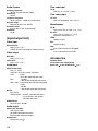
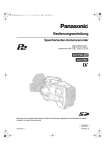
Operating Instructions
Memory Card Camera Recorder
Model No.
AJ-
E
Before operating this product, please read the insructions carefully and save this manual for future use.
F1004T0 -F D
Printed in Japan
ENGLISH
VQT0P98 (E)
PLEASE NOTE:
z When preparing to record important images, always shoot some advance test footage, to verify that both pictures and sound are
being recorded normally.
z Should video or audio recording fail due to a malfunction of this camera-recorder or the P2 cards used, we will not assume liability for such failure.
Software information for this product
1. Customer advisory: This product includes software licensed under the GNU General Public License (GPL) and GNU Lesser
General Public License (LGPL); customers have the right to download, modify, and redistribute source code for this software.
Descriptions of the GPL and LGPL are stored on the installation CD included with this camera-recorder. See the folder named
\LDOC. (The description is the original (written in English)). To download the relevant source code, visit
http://panasonic.biz/sav/.
Please note that we cannot answer any questions you may have about the content, etc. of any source code you may obtain from
the above Web site.
2. This product includes software licensed under the ICU License. A description of the ICU is stored on the installation CD included
with this camera-recorder. See the folder named \LDOC. (The description is the original (written in English)).
3. This product includes software developed by the Apache Software Foundation (http://www.apche.org/). A description of the
Apache is stored on the installation CD included with this camera-recorder. See the folder named \LDOC. (The description is the
original (written in English)).
Unislot® is a registered trademark of Ikegami Tsushinki Co., Ltd.
2
Precautions for Use
DO NOT REMOVE PANEL
UNSCREWING.
COVER
BY
To reduce the risk of electric shock, do not remove
cover. No user serviceable parts inside.
Refer servicing to qualified service personnel.
CAUTION:
TO REDUCE THE RISK OF FIRE OR SHOCK
HAZARD AND ANNOYING INTERFERENCE,
USE THE RECOMMENDED ACCESSORIES
ONLY.
WARNING:
z TO REDUCE THE RISK OF FIRE OR SHOCK
HAZARD, DO NOT EXPOSE THIS EQUIPMENT TO RAIN OR MOISTURE.
z TO REDUCE THE RISK OF FIRE OR SHOCK
HAZARD, KEEP THIS EQUIPMENT AWAY
FROM ALL LIQUIDS-USE AND STORE ONLY
IN LOCATIONS WHICH ARE NOT EXPOSED
TO THE RISK OF DRIPPING OR SPLASHING
LIQUIDS, AND DO NOT PLACE ANY LIQUID
CONTAINERS ON TOP OF THE EQUIPMENT.
CAUTION:
TO REDUCE THE RISK OF FIRE OR SHOCK
HAZARD, REFER MOUNTING OF THE
OPTIONAL INTERFACE BOARD TO AUTHORIZED SERVICE PERSONNEL.
Lithium Battery
Warning
The lithium battery in this equipment must only be
replaced by qualified personnel. When necessary,
contact your local Panasonic supplier.
“The lithium battery is a critical component (type
number CR2032 or BR2032 manufactured by
Panasonic.)
It must never be subjected to excessive heat or discharge. It must therefore only be fitted in equipment designed specifically for its use.
Replacement batteries must be of the same type
and manufacturer. They must be fitted in the same
manner and location as the original battery, with the
correct polarity connections observed.
Do not attempt to re-charge the old battery or reuse it for any other purpose. It should be disposed
of in waste products destined for burial rather than
incineration.”
CAUTION
Danger of explosion if battery is incorrectly
replaced.
Replace only with the same or equivalent type
recommended by the equipment manufacturer.
Discard used batteries according to manufacturer’s instructions.
VARNING
Explosionsfara vid felaktigt batteribyte. Använd
samma batterityp eller en ekvivalent typ som rekommenderas av apparattillverkaren. Kassera
använt batteri enligt fabrikantens instruktion.
ADVARSEL!
Eksplosionsfare ved fejlagtig håndtering.
Udskiftning må kun ske med batteri af samme fabrikat og type. Levér det brugte batteri tilbage til
leverandøren.
VAROITUS
Paristo voi räjähtää, jos se on virheellisesti asennettu.
Vaihda paristo ainoastaan laitevalmistajan suosittelemaan tyypiin. Hävitä käytetty paristo valmistajan ohjeiden mukaisesti.
indicates safety information.
3
Attention/Attentie
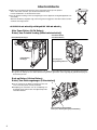
z Batteries are used for the main power source and memory back-up in the product.
At the end of their useful life, you should not throw them away.
Instead, hand them in as small chemical waste.
z Voor de primaire voeding en het reservegeheugen van het apparaat wordt gebruikgemaakt van
een batterij.
Wanneer de batterij is uitgeput, mag u deze niet gewoon weggooien, maar dient u deze als klein
chemisch afval weg te doen.
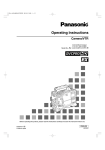
To remove the battery/Verwijderen van de batterij
Main Power Battery (Ni-Cd Battery)
Batterij Voor Primaire Voeding (Nikkelcadmiumbatterij)
Battery/Batterij BP-90 type
Battery/Batterij
BP-90 type
Anton/Bauer Battery
Anton/Bauer-Batterij
Unlocking lever
Ontgrendelingshefboom
z If a battery made by any other manufacturer is to be used, check the Operating Instructions accompanying the battery.
z In geval u een batterij van een anden fabrikant zou gebruiken, gelieve dan eerst zorgvuldig de gebruiksaanwijzing van
deze batterij te lezen.
Back-up Battery (Lithium Battery)
Batterij Voor Reservegeheugen (Lithiumbatterij)
z For the removal of the battery for disposal at the end
of its service life, please consult your dealer.
z Raadpleeg uw leverancier over de verwijdering van
de batterij op het moment dat u het apparaat bij einde
levensduur afdankt.
Back-up Battery (Lithium Battery)
Batterij Voor Reservegeheugen (Lithiumbatterij)
4
Contents
Precautions for Use . . . . . . . . . . . . . . . . . . 3
Chapter 1 Introduction . . . . . . . . . . . . . . 8
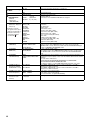
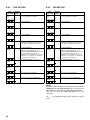
4-4
Selecting Audio Input Signals and
Adjusting Recording Levels . . . . . . . . . . . 35
1-1
Camera Unit Features . . . . . . . . . . . . . . . . 8
4-4-1
Selecting Audio Input Signals . . . . . . . . . . . . . 35
1-2
Recorder/player Features . . . . . . . . . . . . . 9
4-4-2
Adjusting Recording Levels. . . . . . . . . . . . . . . 36
1-3
System Configuration . . . . . . . . . . . . . . . 10
4-4-3
CH3 and CH4 Recording Levels . . . . . . . . . . . 36
Chapter 2
2-1
Parts and their Functions . . 11
4-5
Setting Time Data . . . . . . . . . . . . . . . . . . 37
Power Supply and
4-5-1
Setting the User Bits . . . . . . . . . . . . . . . . . . . . 37
Accessory Mounting Section . . . . . . . . . . 11
4-5-2
Setting the Internal Clock’s Date and Time. . . 38
2-2
Audio (input) Function Section. . . . . . . . . 12
4-5-3
Setting the Time Code . . . . . . . . . . . . . . . . . . 39
2-3
Audio (output) Function Section . . . . . . . 13
4-5-4
Externally Locking the Time Code . . . . . . . . . 39
2-4
Shooting and Recording/Playback
4-5-5
Providing an ID to the Camera . . . . . . . . . . . . 41
Functions Section . . . . . . . . . . . . . . . . . . 14
4-5-6
Setting UMID Information . . . . . . . . . . . . . . . . 41
2-5
Menu Operation Section . . . . . . . . . . . . . 17
4-5-7
Mode Check Screen Displays
2-6
Time Code Section . . . . . . . . . . . . . . . . . 18
2-7
Warning and Status Display Functions . . 19
2-8
Display Window Functions. . . . . . . . . . . . 19
2-9
LCD Monitor. . . . . . . . . . . . . . . . . . . . . . . 20
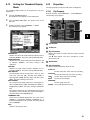
4-6-1
Menu Configuration. . . . . . . . . . . . . . . . . . . . . 42
2-10
Viewfinder . . . . . . . . . . . . . . . . . . . . . . . . 21
4-6-2
Setting Menu Options . . . . . . . . . . . . . . . . . . . 43
4-6-3
Selecting Options for USER MENU . . . . . . . . 44
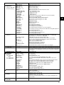
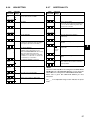
Chapter 3
Recording and Playback. . . 22
(MODE CHECK button function). . . . . . . . . . . 42
4-6
Menu Displays in the Viewfinder
Screen . . . . . . . . . . . . . . . . . . . . . . . . . . . 42
3-1
P2 Cards . . . . . . . . . . . . . . . . . . . . . . . . . 22
3-2
Basic Procedures. . . . . . . . . . . . . . . . . . . 24
4-7-1
Lamps in the Viewfinder Screen . . . . . . . . . . . 45
3-3
Normal Recording . . . . . . . . . . . . . . . . . . 26
4-7-2
Viewfinder Status Indication Layout . . . . . . . . 45
3-4
PRE-RECORDING function. . . . . . . . . . . 26
4-7-3
Selecting Viewfinder Display Information . . . . 45
3-5
Loop Recording . . . . . . . . . . . . . . . . . . . . 27
4-7-4
Display Modes and Setting
3-6
Recording Review Function . . . . . . . . . . . 27
3-7
Normal and Variable Speed Playback . . . 28
4-7-5
3-8
Voice Memo Function . . . . . . . . . . . . . . . 28
4-7-6
3-9
Shot Mark Function . . . . . . . . . . . . . . . . . 29
Chapter 4
4-1
Adjustments and
Settings for Recording . . . . 30
Adjusting the White balance and
Black Balance . . . . . . . . . . . . . . . . . . . . . 30
4-1-1
Adjusting the White Balance . . . . . . . . . . . . . .30
4-1-2
Adjusting the Black Balance . . . . . . . . . . . . . .32
4-2
Setting the Electronic Shutter . . . . . . . . . 33
4-2-1
Shutter Modes . . . . . . . . . . . . . . . . . . . . . . . . .33
4-2-2
Setting the Shutter Mode and Speed . . . . . . . .33
4-2-3
Placing the Camera-recorder
in SYNCHRO SCAN Mode . . . . . . . . . . . . . . .34
4-3
4-7
Viewfinder Screen Status Displays . . . . . 45
Changes/adjustment Result Messages. . . . . . 51
Setting the Marker Displays . . . . . . . . . . . . . . 52
Marker Check Screen Displays
(MARKER SELECT button function). . . . . . . . 52
4-7-7
Checking Return Video Signal
in the Viewfinder . . . . . . . . . . . . . . . . . . . . . . . 52
4-8
Adjusting and setting the LCD monitor . . 53
4-9
Menu-driven Function Setup . . . . . . . . . . 54
4-9-1
Setting the Switchover of USER SW GAIN. . . 54
4-9-2
Selecting Video Output Signals. . . . . . . . . . . . 54
4-9-3
Selecting Function for
the FRONT AUDIO LEVEL Control. . . . . . . . . 54
4-9-4
Assigning Functions to USER MAIN, USER1
and USER2 Buttons . . . . . . . . . . . . . . . . . . . . 55
4-9-5
Setting Color Temperature Manually . . . . . . . 55
Selecting Recording Signals and
Recording System . . . . . . . . . . . . . . . . . . 34
4-3-1
Selecting the Recording Signals. . . . . . . . . . . .34
4-3-2
Selecting the Recording System . . . . . . . . . . .35
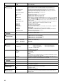
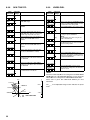
5
4-10
Handling data. . . . . . . . . . . . . . . . . . . . . . 56
Properties. . . . . . . . . . . . . . . . . . . . . . . . . 83
4-10-1
Handling SD Cards . . . . . . . . . . . . . . . . . . . . .56
6-13-1
Clip Property . . . . . . . . . . . . . . . . . . . . . . . . . . 83
4-10-2
Formatting, Writing and
6-13-2
P2 Card Status Display . . . . . . . . . . . . . . . . . . 84
Reading an SD Card . . . . . . . . . . . . . . . . . . . .56
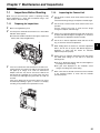
Chapter 7
Maintenance and
Inspections . . . . . . . . . . . . . . 85
4-10-3
How to Use the User Data . . . . . . . . . . . . . . . .60
4-10-4
How to Use Scene File Data . . . . . . . . . . . . . .61
4-10-5
Resetting Menu Option Settings to Defaults . .63
7-1-1
Preparing for Inspections . . . . . . . . . . . . . . . . 85
4-10-6
Lens File Data . . . . . . . . . . . . . . . . . . . . . . . . .63
7-1-2
Inspecting the Camera Unit. . . . . . . . . . . . . . . 85
7-1-3
Inspecting the Memory Recording Functions . 86
Chapter 5
5-1
5-1-1
5-1-2
5-2
Preparation. . . . . . . . . . . . . . 64
Power Supply. . . . . . . . . . . . . . . . . . . . . . 64
5-3
5-4-1
7-2
Inspections Before Shooting . . . . . . . . . . 85
Maintenance . . . . . . . . . . . . . . . . . . . . . . 87
7-2-1
setting the battery type. . . . . . . . . . . . . . . . . . .64
7-2-2
Phenomenon Inherent to CCD Cameras . . . . 87
Using an AC Power Supply . . . . . . . . . . . . . . .67
7-2-3
Replacing the Backup Battery. . . . . . . . . . . . . 87
Mounting the Viewfinder and
7-2-4
Connector Signals. . . . . . . . . . . . . . . . . . . . . . 88
7-3
Cleaning Inside the Viewfinder . . . . . . . . . . . . 87
Warning System. . . . . . . . . . . . . . . . . . . . 89
Mounting the lens and Performing
7-3-1
Warning Description Tables . . . . . . . . . . . . . . 89
the Flange Back and White Shading
7-3-2
Error Codes. . . . . . . . . . . . . . . . . . . . . . . . . . . 90
Adjustments . . . . . . . . . . . . . . . . . . . . . . . 68
5-4
7-1
Mounting the battery and
Adjusting its Position . . . . . . . . . . . . . . . . 67
Chapter 8
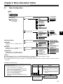
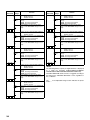
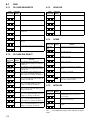
Menu Description Tables . . 91
Preparing for Audio Input. . . . . . . . . . . . . 72
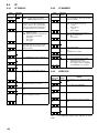
8-1
Menu Configuration . . . . . . . . . . . . . . . . . 91
When Using the Front Microphone . . . . . . . . .72
8-2
SYSTEM SETTING . . . . . . . . . . . . . . . . . 92
5-4-2
When Using a Wireless Receiver . . . . . . . . . .72
8-2-1
5-4-3
When Using Audio Devices . . . . . . . . . . . . . . .73
8-2-2
OPTION MODE. . . . . . . . . . . . . . . . . . . . . . . . 92
Mounting the Camera on a Tripod . . . . . . 73
8-2-3
REC FUNCTION . . . . . . . . . . . . . . . . . . . . . . . 93
5-6
Attaching the Shoulder Strap. . . . . . . . . . 74
8-2-4
OUTPUT SEL . . . . . . . . . . . . . . . . . . . . . . . . . 93
5-7
Attaching the Rain Cover . . . . . . . . . . . . . 74
8-2-5
LCD MONITOR . . . . . . . . . . . . . . . . . . . . . . . . 94
5-8
Connecting the AJ-EC3E
8-2-6
GENLOCK. . . . . . . . . . . . . . . . . . . . . . . . . . . . 94
5-5
Extension Controller . . . . . . . . . . . . . . . . 74
8-3
SYSTEM MODE . . . . . . . . . . . . . . . . . . . . . . . 92
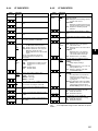
PAINT . . . . . . . . . . . . . . . . . . . . . . . . . . . 94
Attaching the Front Audio Level
8-3-1
ROP . . . . . . . . . . . . . . . . . . . . . . . . . . . . . . . . 94
Control Knob . . . . . . . . . . . . . . . . . . . . . . 75
8-3-2
MATRIX. . . . . . . . . . . . . . . . . . . . . . . . . . . . . . 95
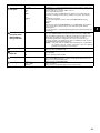
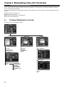
Manipulating Clips
with Thumbnails . . . . . . . . . 76
8-3-3
COLOR CORRECTION . . . . . . . . . . . . . . . . . 95
8-3-4
LOW SETTING . . . . . . . . . . . . . . . . . . . . . . . . 96
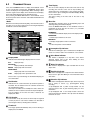
6-1
Thumbnail Manipulations Overview . . . . . 76
8-3-5
MID SETTING . . . . . . . . . . . . . . . . . . . . . . . . . 96
6-2
Thumbnail Screen . . . . . . . . . . . . . . . . . . 77
8-3-6
HIGH SETTING. . . . . . . . . . . . . . . . . . . . . . . . 97
6-3
Selecting Thumbnails . . . . . . . . . . . . . . . 78
8-3-7
ADDITIONAL DTL. . . . . . . . . . . . . . . . . . . . . . 97
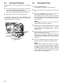
6-4
Playing Back Clips . . . . . . . . . . . . . . . . . . 78
8-3-8
SKIN TONE DTL . . . . . . . . . . . . . . . . . . . . . . . 98
6-5
Switching the Thumbnail Display . . . . . . . 79
8-3-9
KNEE/LEVEL . . . . . . . . . . . . . . . . . . . . . . . . . 98
6-6
Shot Mark . . . . . . . . . . . . . . . . . . . . . . . . 79
8-3-10
GAMMA. . . . . . . . . . . . . . . . . . . . . . . . . . . . . . 99
6-7
Voice Memo. . . . . . . . . . . . . . . . . . . . . . . 80
8-3-11
FLARE. . . . . . . . . . . . . . . . . . . . . . . . . . . . . . . 99
6-7-1
Playing Back Voice Memos . . . . . . . . . . . . . . .80
8-3-12
CAMERA SETTING . . . . . . . . . . . . . . . . . . . . 99
6-7-2
Recording a Voice Memo. . . . . . . . . . . . . . . . .80
6-7-3
Deleting Voice Memos . . . . . . . . . . . . . . . . . . .81
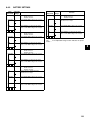
8-4-1
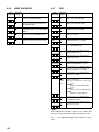
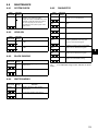
VF DISPLAY . . . . . . . . . . . . . . . . . . . . . . . . . 100
6-8
Deleting Clips. . . . . . . . . . . . . . . . . . . . . . 81
8-4-2
VF MARKER . . . . . . . . . . . . . . . . . . . . . . . . . 100
6-9
Restoring Clips . . . . . . . . . . . . . . . . . . . . 81
8-4-3
USER BOX . . . . . . . . . . . . . . . . . . . . . . . . . . 100
6-10
Formatting a P2 Card . . . . . . . . . . . . . . . 82
8-4-4
VF INDICATOR1. . . . . . . . . . . . . . . . . . . . . . 101
6-11
Formatting SD Cards . . . . . . . . . . . . . . . . 82
8-4-5
VF INDICATOR2. . . . . . . . . . . . . . . . . . . . . . 101
6-12
Setting the Thumbnail Display Mode . . . . 83
8-4-6
MODE CHECK IND. . . . . . . . . . . . . . . . . . . . 102
8-4-7
!LED . . . . . . . . . . . . . . . . . . . . . . . . . . . . . . . 102
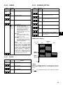
5-9
Chapter 6
6
6-13
8-4
VF . . . . . . . . . . . . . . . . . . . . . . . . . . . . . 100
8-5
CAM OPERATION. . . . . . . . . . . . . . . . . 103
8-5-1
CAMERA ID . . . . . . . . . . . . . . . . . . . . . . . . . .103
8-5-2
SHUTTER SPEED . . . . . . . . . . . . . . . . . . . . .103
8-5-3
SHUTTER SELECT . . . . . . . . . . . . . . . . . . . .103
8-5-4
USER SW . . . . . . . . . . . . . . . . . . . . . . . . . . .104
8-5-5
SW MODE . . . . . . . . . . . . . . . . . . . . . . . . . . .104
8-5-6
WHITE BALANCE MODE . . . . . . . . . . . . . . .105
8-5-7
USER SW GAIN . . . . . . . . . . . . . . . . . . . . . .105
8-5-8
IRIS . . . . . . . . . . . . . . . . . . . . . . . . . . . . . . . .106
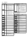
8-6
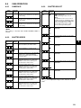
MAIN OPERATION . . . . . . . . . . . . . . . . 106
8-6-1
BATTERY/P2CARD . . . . . . . . . . . . . . . . . . . .106
8-6-2
BATTERY SETTING1 . . . . . . . . . . . . . . . . . .107
8-6-3
BATTERY SETTING2 . . . . . . . . . . . . . . . . . .109
8-6-4
MIC/AUDIO1 . . . . . . . . . . . . . . . . . . . . . . . . .110
8-6-5
MIC/AUDIO2 . . . . . . . . . . . . . . . . . . . . . . . . .110
8-6-6
TC/UB . . . . . . . . . . . . . . . . . . . . . . . . . . . . . .111
8-6-7
UMID SET/INFO . . . . . . . . . . . . . . . . . . . . . .111
8-7
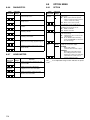
FILE . . . . . . . . . . . . . . . . . . . . . . . . . . . . 112
8-7-1
SD CARD READ/WRITE . . . . . . . . . . . . . . . .112
8-7-2
SD CARD R/W SELECT . . . . . . . . . . . . . . . .112
8-7-3
LENS FILE . . . . . . . . . . . . . . . . . . . . . . . . . . .112
8-7-4
SCENE. . . . . . . . . . . . . . . . . . . . . . . . . . . . . .112
8-7-5
INITIALIZE . . . . . . . . . . . . . . . . . . . . . . . . . . .112
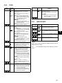
8-8
8-8-1
MAINTENANCE. . . . . . . . . . . . . . . . . . . 113
SYSTEM CHECK. . . . . . . . . . . . . . . . . . . . . .113
8-8-2
LENS ADJ . . . . . . . . . . . . . . . . . . . . . . . . . . .113
8-8-3
BLACK SHADING . . . . . . . . . . . . . . . . . . . . .113
8-8-4
WHITE SHADING . . . . . . . . . . . . . . . . . . . . .113
8-8-5
DIAGNOSTIC1. . . . . . . . . . . . . . . . . . . . . . . .113
8-8-6
DIAGNOSTIC2. . . . . . . . . . . . . . . . . . . . . . . .114
8-8-7
HOURS METER . . . . . . . . . . . . . . . . . . . . . .114
8-9
8-9-1
OPTION MENU . . . . . . . . . . . . . . . . . . . 114
OPTION . . . . . . . . . . . . . . . . . . . . . . . . . . . . .114
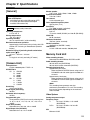
Chapter 9
Specifications . . . . . . . . . . 115
7
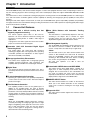
Chapter 1 Introduction
The AJ-SPX900E memory card camera-recorder integrates a camera unit equipped with three CCDs, incorporating a 2/3-inch onchip lens featuring progressive drive technology, and a video recorder/player (VTR) that supports DVCPRO50, DVCPRO and DV
formats.
The camera offers a choice of interlaced scanning and progressive scanning modes. The AJ-SPX900E provides for a wide range of
uses, with such features as film-like gamma correction capability for authoring, and storage-type gain-up capability for news picture
shooting.
Utilising P2 cards, which require no mechanism, as media, your AJ-SPX900E offers greater responsibility, operability, and portability.
It is highly resistant to shock and vibration during recording, and therefore ensures stable operation for capturing quality video images
under the most adverse conditions.
1-1
Camera Unit Features
/ Three CCDs with a 2/3-inch on-chip lens that
supports progressive scanning
/ Auto White Balance with Automatic Tracking
capability
The camera supports aspect ratios of 16:9 and 4:3.
Operators can choose between interlaced scanning and
progressive scanning modes, to handle a wide range of
applications.
In progressive scan mode, signals from and to the recorder/
player are converted to interlaced signals.
The white balance is automatically adjusted in real time,
according to the subject. This is effective for urgent
recording, where you can’t spare the time to make an
adjustment through the auto white balance feature.
/ Innovative 14-bit A/D Converted Digital Signal
Processing Circuit
This model utilises new 14-bit linear A/D conversion
technology to digitise video. The signal processor, operating
at 36 MHz, provides finer reproduction of video, together
with enhanced stability and reliability.
/ Storage-type Sensitivity Enhancement
The camera unit is equipped with a storage-type gain-up
capability featuring progressive drive technology. This
capability adds up to 20 dB to the standard gain increase.
/ Digital Zoom
The camera unit features progressive digital zoom. This is
particularly effective when you want to zoom-in closer on the
subject.
/ 12-axis Independent color Correction
Operating as a paint function, this capability independently
corrects colors for each of the 12 axes. This feature helps to
produce fine images.
/ Film-like Gamma Correction
This capability provides a choice of four gamma types. In
addition to the standard mode, two types of film-like
gammas are available to help enhance video expression in
productions. The newly developed News Gamma accurately
records changes in shadow areas and reduces whiteout in
highlighted areas. This is particularly useful for on-site news
shooting.
<Note>
While your AJ-SPX900E supports progressive scanning,
constantly increasing the storage-type gain causes a slight
degree of brightening at the upper left corner of the screen
due to CCD characteristics. Note also that the dynamic
range of video signals in progressive scanning mode is
about half that in interlaced driving mode.
8
/ Data Management Capability
Your AJ-SPX900E has inbuilt data storage capacity for one
user and four scene files. In addition, an SD card can be
used as a setup card to store data for up to eight setups.
<Note>
The SD cards used on your video camera-recorder must
conform to SD standards. The cards must be formatted
using the AJ-SPX900E. However, SD cards formatted,
according to SD standards with other devices, including
PCs, are also recognised by the AJ-SPX900E.
SD cards with capacities of 8 MB or more are
recommended.
/ Customisable USER Buttons and USER MENU
The camera unit has three USER buttons, operable by a
single press, to which frequently used function may be
assigned. The on-screen menu is also customisable. You
can create an original user menu screen by selecting
frequently used menu items. The menu thus created can be
displayed with a single touch of the MENU button.
/ MARKER SELECT Button
Your video camera-recorder has a button on the front that
allows you to view marker information on the viewfinder
screen. This is useful for checking the view angle during
shooting.
/ Support for ECU
Your video camera-recorder supports the extension control
unit AJ-EC3E.
1-2
Recorder/player Features
/ Multiple Slots
/ Voice Memos & Shot Marks
The AJ-SPX900E is equipped with five slots for P2 cards.
Up to five cards may be inserted in these slots for
continuous recording. They also provide new recording
capabilities specific to memory cards.
z Hot-Swap recording
The Hot-Swap capability allows cards not in use to be
replaced without interrupting recording. This facilitates
continuous recording.
z Loop recording
The AJ-SPX900E can retain a certain amount of
previously recorded material by continuously looprecording data into a specified recording area.
z PRE-RECORDING function
In standby status, the AJ-SPX900E always stores video and
sound input to the camera for up to 15 seconds (for the
DVCPRO format). This means that the PRE-RECORDING
function, when turned on, records the video and sound for a
preceding duration preset by the user. This feature recovers
critical moments that you might have missed.
z Data protection
Data on P2 cards will not be lost due to overwriting unless
the files are deleted or the cards are initialised.
Recordings are written only to free space.
/ Format User-switchable
DVCPRO and DV
Between
Each clip can incorporate comments, in the form of voice
memos, associated with the time code, together with shot
marks which, for example, can help you distinguish OK cuts
from reject cuts.
Both voice memos and shot marks can be added to
selected clips during and after a recording. This is helpful for
editing recorded video.
/ Support for
installed)
SDI
Output
(when
AJ-YA902AG
The AJ-SPX900E, when equipped with the extension board
AJ-YA902AG, can output SDI signals from the VIDEO OUT
connector.
/ Front-mounted Sound Level Control Mechanism
The AJ-SPX900E features a front-mounted control for fine
adjustment of the sound recording level. This control is
particularly effective for adjusting the sound level when you
are shooting without a sound recordist. The control can be
disabled.
/ Support for Built-in Unislot® Wireless Receive
The AJ-SPX900E is designed to support an optional slot-in
wireless receiver.
DVCPRO50,
Recorded video is compressed through a component digital
recording method that uses a state-of-the-art compression
technology, and sound is recorded using the noncompression PCM recording method, which excels in such
areas as S/N ratio, frequency bands, waveform properties
and reproducibility of fine areas. These methods further
enhance the quality of images and sound.
The format is user-selectable, according to your purpose:
e.g., DVCPRO50 for higher image quality, or DVCPRO for
cost efficiency. DV format is also supported.
<Note>
When the clip is played back in the format not selected on the
menu, the picture may be disturbed until the format is detected.
/ 4-channel Digital Audio Recording (all formats)
All formats - DVCPRO, DV and DVCPRO50 - support 4-channel
digital audio recording with high-quality sound (48 kHz/16 bits).
/ Recording Review Capability
This capability automatically plays back the last 2 to 10
seconds of recorded video, allowing you to quickly check the
recorded contents.
/ Built-in Time Code Generator/reader
A special-purpose secondary code track can be used to
record and reproduce time code information.
/ Support for Metadata
The AJ-SPX900E is capable of recording positional
information (latitudes, longitudes and altitudes), as UMID
information (metadata), from the GPS unit AJ-GPS900G
(optional accessory).
This information is also useful in managing information on
P2 cards.
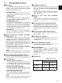
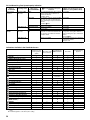
/ Recording Time
(Number of cards used: 1)
/ Clip Thumbnailing
z Automatic generation of thumbnails
The AJ-SPX900E automatically generates a thumbnail for
each recording cut (clip). It is possible to make use of this
on the camera-recorder as well as for non-linear editing
purposes, and after uploading to a server.
z Thumbnail display on the LCD monitor
The 3.5-inch color LCD side of the your video camera-recorder
can provide a multi-screen view of 12 clip thumbnails. You can
choose a desired clip to playback instantly.
z Seamless playback of selected clips
You can select more than one clip from the thumbnail view
for continuous playback and output of seamless video.
Recording Format
Card #
DVCPRO
(Audio 2ch)
DVCPRO50
(Audio 4ch)
AJ-P2C002SG
Approx.
8 minutes
Approx.
4 minutes
AJ-P2C004HG
Approx.
16 minutes
Approx.
8 minutes
(For more information, see the instruction manual for the
appropriate memory card.)
<Note>
When the clips recorded in different format are played back
continuously, seamless playback may not be available.
9
1
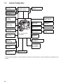
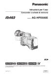
1-3
System Configuration
Microphone kit:
AJ-MC700P
Unislot® wireless
microphone receiver:
Sennheiser EK3041
Extension control unit:
AJ-EC3E
Stereo microphone:*
AJ-MC900G
DIONIC90/160
HYTRON50/100/120
PRO14, TRIM14
Viewfinder:
AJ-VF15B
AJ-VF20WB
Lens:
(Bayonet type)
Fujinon, Canon
GPS unit:
AJ-GPS900G
Tripod adaptor:
SHAN-TM700
Video camera-recorder
AJ-SPX900E
ENDURA50/80
BP-L60/90
NP-1 type
Battery mount
NP-L50
BP-90 type
Battery mount
BP-H120
HP-90L
AC adaptor:
AJ-B75
SDI output board:
AJ-YA902AG
Rain cover:
SHAN-RC700
P2 Cards:
AJ-P2C002SG
AJ-P2C004HG
Soft carry-case:
AJ-SC900
Hard carry-case:
AJ-HT901
V mount type
Battery plate
SD Memory cards
* To install a stereo microphone, an extra modification is required. For more information, contact your distributor or designated service
provider.
10
Chapter 2 Parts and their Functions
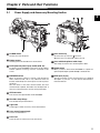
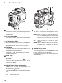
2-1
Power Supply and Accessory Mounting Section
2
POWER switch
Lens mount cap
Used to turn on/off the power.
To remove the cap, raise the
lens lever.
When the lens is not mounted, replace the cap.
Battery mount
A battery pack from Anton/Bauer is mounted here.
Lens cable/microphone cable clamp
This clamp secures the lens and microphone cables.
DC IN (external power input) socket (XLR, 4P)
To operate your AJ-SPX900E on AC power, the AC adaptor
AJ-B75 (optional accessory) must be connected to this
socket.
Tripod mount
BREAKER switch
LENS jack (12-pin)
When an excessive amount of current is fed through the
video camera-recorder, due to any abnormal event, the
breaker automatically turns off the power in order to protect
the device.
After the interior of the video camera-recorder has been
checked and/or repaired, this button must be depressed. If
there is no unusual reaction, the unit can be powered-up.
The lens connection cord is connected here. For a detailed
description of your lens, see the relevant manufacturer’s
instruction manual.
When you want to mount the AJ-SPX900E on a tripod, the
optional tripod adaptor (SHAN-TM700) is attached here.
GPS connector
This connects the optional GPS unit AJ-GPS900G.
Shoulder strap fittings
The shoulder strap is attached here.
Light shoe
A video light or similar accessory can be attached here.
Lens mount (bayonet type)
The lens is attached here.
Lens lever
Lower this lever to lock the lens to the lens mount.
11
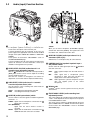
2-2
Audio (input) Function Section
MIC IN (microphone input) jack (XLR, 3-pin)
A microphone (optional accessory) is connected here.
Power for the microphone comes from this jack.
A remote microphone may be connected. In this case, the
power supply to the appropriate connector must be enabled
through menu option FRONT MIC POWER or REAR MIC
POWER.
These options are found in the <MIC/AUDIO2> screen on
the MAIN OPERATION page.
A stereo microphone may be connected, but you will need to
replace the connector. For more information, contact your
distributor or designated service provider.
AUDIO LEVEL CH1/CH2 (audio channel 1 & 2
recording level adjustment) controls
With the
AUDIO SELECT CH1/CH2 switch positioned to
[MAN], these controls can be used to adjust the recording
levels for Audio Channels 1/2.
Note that the controls are designed to be locked. For
adjustment, each control must be depressed while turning.
AUDIO SELECT CH1/CH2 (audio channel 1 & 2 automatic/
manual level adjustment selector) switch
Use this switch to select recording level control mode for
Audio Channels 1 and 2.
AUTO:
MAN:
Recording level automatically controlled.
Recording level manually controlled.
AUDIO IN (audio input selector) switch
Use this switch to select the signals recorded through Audio
Channels 1 - 4.
FRONT: Signal from the microphone connected to the
MIC IN jack is recorded.
W.L. (WIRELESS)
Signal from the slot-in wireless receiver is
recorded.
REAR: Signal from the audio device connected to the
AUDIO IN CH1/CH2 connector is recorded.
12
<Note>
When you use stereo microphone (AJ-MC900G optional),
set both CH1 and CH2 to [FRONT]. The signal from L CH is
recorded to CH1 and that from R CH to CH2.
AUDIO IN CH1/CH2 (audio input channel 1 & 2)
connectors (XLR, 3-pin)
Audio devices or a microphone may be connected here.
LINE/MIC/+48V (line input/mic input/mic input +
48V) selector switch
Used to select the audio signal input from the
CH1/CH2 connectors.
LINE:
MIC:
+ 48V:
AUDIO IN
Audio signal line-input from the audio device is
input.
Audio signal from a self-powered (active)
microphone is input. (The main unit does not
supply power to the remote microphone).
Audio signal from a passive microphone is input.
(The unit supplies power to the remote
microphone).
Wireless slot
A Unislot® wireless receiver (optional accessory) may be
attached here.
FRONT AUDIO LEVEL (audio recording level
adjustment) control
This control adjusts the recording levels for Audio Channels
1 and 2. Level adjustment does not depend on the position
of the AUDIO SELECT switch.
The control can be enabled or disabled through the menu
options FRONT VR CH1 or FRONT VR CH2. These options
can be found in the <MIC/AUDIO1> screen on the MAIN
OPERATION page.
2-3
Audio (output) Function Section
AUDIO OUT connector (XLR, 5-pin)
Speakers
This connector outputs audio signals recorded on Channels
1/2 or 3/4.
Output signals are selected with the MONITOR SELECT
CH1/2 / CH3/4 selector switch.
The speakers output EE sound during recording, and
reproduced sound during playback.
The speakers emit an alarm sound when the warning lamp
blinks and/or the indicator activates.
When the
PHONES jack is connected with earphones,
sound from the speaker is automatically muted.
MONITOR SELECT (audio channel) CH1/2 / CH3/4
selector switch
Use this switch to select the audio channel whose signals
are output to the speakers, earphones or AUDIO OUT
connector.
CH1/2:
CH3/4:
Signals on Audio Channels 1 and 2 are output.
Signals on Audio Channels 3 and 4 are output.
The channel indications on the display window and on the
audio level meter in the viewfinder are synchronised with
this selector switch.
When a voice memo is being played back, the recorded
voice is output to the speakers and earphones, regardless
of the switch position.
<Note>
Whenever two-channel recording is performed in the
DVCPRO25 or DV format, the signals on Audio Channels 1
and 2 are output and indicated.
MONITOR SELECT (audio selection) CH1/3 / ST /
CH2/4 selector switch
PHONES (earphones) jack (mini jack)
This connector is designed for audio monitoring (stereo)
earphones. When earphones are connected, sound from
the speakers is automatically muted.
Both the front and rear connectors output the same sound.
DC OUT (DC power supply) output socket
This output socket is designed for 12-VDC. It provides a
maximum current of 1 A.
Voice memo microphone
Used to record a voice memo.
For more information on voice memos, see [3-8 Voice Memo
Function].
VOICE MEMO button
Used to record a voice memo during recording or playback,
or recording or playback is paused. Another press of the
button stops voice memo recording.
The MONITOR SELECT switch is synchronised with the
audio signal output to the speakers and earphones, and
from the AUDIO OUT connector.
CH1/3:
ST:
CH2/4:
Monitor
switch
CH1/3
Signal on Audio Channel 1 or 3 is output.
Stereo audio signals on Audio Channels 1 and 2
or Audio Channels 3 or 4 are output. The stereo
signals can be changed to mixed signals using a
menu option.
Signal on Audio Channel 2 or 4 is output.
MONITOR SELECT switch
CH1/2
CH3/4
Audio Channel 1
Audio Channel 3
Stereo signals from
Stereo signals from
Audio Channels 1 and 2* Audio Channels 3 and 4*
ST
CH2/4
Audio Channel 2
Audio Channel 4
* You can select between stereo and mixed signal types using the
menu option MONITOR SELECT. This menu option can be found
in the <MIC/AUDIO2> screen on the MAIN OPERATION page.
MONITOR (volume) control
Used to control the volume of sound output from the monitor
speakers and earphones.
ALARM (warning alarm volume adjustment)
Used to control the volume of the warning sound emitted
from
speakers or earphones connected to the
PHONES jack.
If the control is minimised, no alarm is audible.
13
2
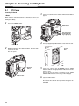
2-4
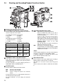
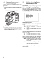
Shooting and Recording/Playback Functions Section
/ Shooting and Recording (camera unit)
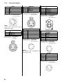
CC FILTER/ND FILTER (filter selector) controls
Use this knob to select a filter depending on the luminance
and color temperature of the subject.
AUTO W/B (white/black) BAL switch
AWB:
CC FILTER knob (outside, large diameter)
A: Cross filter
B: 3200 K
C: 4300 K
D: 6300 K
ND FILTER knob (inside, small diameter)
1: CLEAR (transparent)
2: 1/4 ND
3: 1/16 ND
4: 1/64 ND
Examples of filter selection according to shooting conditions
Shooting conditions
CC FILTER
ND FILTER
Sunrise, sunset, studio
B (3200 K)
1 (CLEAR)
Clear outdoor environments
C (4300 K) or 2 (1/4 ND) or
D (6300 K)
3 (1/16 ND)
Cloudy/rainy outdoor
environments
D (6300 K)
1 (CLEAR) or
2 (1/4 ND)
<Note>
Clear, bright scenes such as
C (4300 K) or 3 (1/16 ND) or
snowscape, high mountains,
D (6300 K)
4 (1/64 ND)
beaches, etc.
To stop automatic adjustment of the white or black balance
in progress, set the switch to either ([AWB] or [ABB]).
If automatic adjustment is canceled, the value in effect
before automatic adjustment will be used.
USER MAIN, USER 1 and USER 2 buttons
Gain selector switch
These buttons can be assigned user-selected functions,
using a menu option. Each button, when pressed, performs
the assigned function.
For more information, see [4-9-4 Assigning Functions to
USER MAIN, USER1 and USER2 Buttons.
Use this switch to select video amplifier gain, according to
lighting conditions under which you are shooting.
The values for L, M, and H can be preset using menu
options.
These are factory-set to 0 dB for L, 9 dB for M, and 18 dB for
H.
SHUTTER switch
Used to enable or disable the electronic shutter.
OFF:
ON:
SEL:
Electronic shutter disabled.
Electronic shutter enabled.
Used to change the speed of the electronic
shutter.
This dial switch returns to its original position. Each turn of
the switch alters the shutter speed.
For more information, see [4-2 Setting the Electronic
Shutter].
14
ABB:
White balance is automatically adjusted.
When the WHITE BAL switch on the side is
positioned at [A] or [B], the adjusted value is
stored in the memory.
However, if “VAR” is selected for the menu options
AWB A and AWB B, the value set through the
menu options is used, and this function does not
work. Menu options can be found in the <WHITE
BALANCE MODE> screen on the CAM
OPERATION page.
Note also that when the switch is positioned at
PRST this function does not work.
Back balance is automatically adjusted.
To automatically correct black shading, the AUTO
W/B BAL switch must be pressed toward [ABB] for
longer than five seconds.
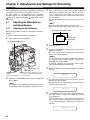
OUTPUT/AUTO KNEE selector switch
MARKER SELECT button
Used to select the video signals sent from the camera unit to
the memory, viewfinder and video monitor.
This button selects the marker information indicated on the
viewfinder screen. It switches between two marker
information indications, which can be selected using a menu
option. Pressing this button once switches the indicated
marker information from A (Marker A) to B (Marker B), and
pressing again switches B to OFF (no marker). When the
power is turned on, the last selected indication before
power-down appears.
For more information, see [4-7-6 Marker Check Screen
Displays (MARKER SELECT button function)].
CAM. AUTO KNEE ON:
Video being recorded through the camera is sent with the
auto knee circuit activated.
CAM. AUTO KNEE OFF:
Video being recorded through the camera is sent in
manual knee mode.
BARS:
Color bar signal is output. The auto knee circuit does not
work.
You can select between four types of color bar signal. For
more information, see [8-5-5 SW MODE].
Auto Knee function
Usually, when you adjust levels to shoot people or scenery against a
strongly lighted background, the background will be totally whited-out, with
buildings and other objects blurred. In this case, the auto knee function
reproduces the background clearly. This function is effective when:
• The subject is a person positioned in the shade under a clear sky.
• The subject is a person inside a car or building, and you also want to
capture the background visible through a window.
• The subject is a high-contrast scene.
WHITE BAL (white balance memory selector)
switch
Used to select the white balance adjustment method.
PRST:
A or B:
Use this when you have no time to adjust the
white balance.
The value for the white balance is factory-set to
3200 K.
It can be changed to any color temperature using
a menu option. For more information, see [4-9-5
Setting Color Temperature Manually].
Pressing the
AUTO W/B BAL Switch toward
[AWB] automatically adjusts the white balance,
saving the adjusted value in Memory A or B. For
more information, see [4-1-1 Adjusting the White
Balance].
Your video camera-recorder is factory-set to save the
adjusted value. Through a menu option, the auto-tracking
white balance (ATW) can be assigned to B, or desired color
temperatures can be assigned to A and B.
For more information, see [4-1-1 Adjusting the White
Balance].
SYNCHRO SCAN ADJUSTMENT buttons
These buttons are enabled when the
shutter switch is
positioned at [ON] and synchro scan is selected.
They are used to adjust the speed of the synchro scan.
The –ޓbutton decreases shutter speed; the + button
increases shutter speed.
If you shoot a PC monitor, for example, you should adjust
shutter speed so that the horizontal bars in the viewfinder
will produce less noise.
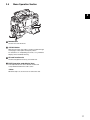
/ Shooting
and
Recording/Playback
Section (recording)
Function
REC START/STOP button
Pressing this button starts recording, pressing again stops
recording.
This button has the same function as the
REC button on
the handle and the VTR button at the lens.
SHOT MARK button
Pressing this button while recording adds a shot mark to the
thumbnail of that clip. This button also adds a shot mark to
any thumbnail selected on the LCD monitor.
For more information on shot marks, see [3-9 Shot Mark
Function].
SAVE ON/OFF switch
Used to select the power supply method for each output
section.
ON:
OFF:
The output selected through the menu option
SAVE SW is power-saved. This option can be
found on the OPTION MODE screen on the
SYSTEM SETTINGS page.
Power saving is canceled.
<Note>
MODE CHECK button
Each press of this button changes the screen type in the
viewfinder in the following order: STATUS, !LED,
FUNCTION, AUDIO.
This does not affect the signal output from the camera.
During recording, this switch produces no effect. The power
supply method is switched after recording is finished.
VIDEO OUT CHARACTER switch
This switch controls the superimposition of characters onto
the video output from the VIDEO OUT connector.
ON:
OFF:
Characters are superimposed.
Characters are not superimposed.
For types of characters, see [4-9-2 Selecting Video Output
Signals].
15
2
OUTPUT SEL (output signal selection) switch
USB 2.0 connector
Used to switch the signals output from the VIDEO OUT and
MON OUT connectors.
A USB 2.0 cable is connected here. (To be supported in the
near future.)
MEM:
CAM:
OFF:
In EE (recording) mode, video from the camera is
output. In VV (playback) mode, playback signal
from a P2 card is output.
Video from the camera is output constantly.
Video is not output, and the video camerarecorder operates in power-saving mode.
Note that the audio output is synchronised with the video.
For types of video outputs, see [4-9-2 Selecting Video
Output Signals].
REW (rewind) button and lamp
During pause, this button performs a fast-reverse playback
with the lamp blinking.
During playback, it performs an approximately 4C fastreverse playback with the PLAY and REW lamps blinking.
If this button is pressed when playback is paused, the start
of the clip being played back is located in pause mode.
GENLOCK IN connector
This connector is used to input a reference signal when the
camera unit is gen-locked, or when the time code is
externally locked. If VIDEO is selected for the menu option
REC SIGNAL, the connector can be used to record actual
signals. The menu option REC SIGNAL is found on the
SYSTEM MODE screen on the SYSTEM SETTINGS page.
<Notes>
z The reference input signal must be a standard VBS
(Video Burst Sync).
z If you need to synchronise the input signal with the AJSPX900E when “VIDEO” is selected for the REC SIGNAL,
set the menu option GENLOCK to “EXT”. The option
GENLOCK is found on the GENLOCK screen, which is
accessible from the SYSTEM SETTING page.
MON OUT (monitor output) connector
FF (fast forward) button and lamp
During pause, this button is used to perform fast playback
with the lamp blinking.
During playback, it performs an approximately 4C fast
playback with the PLAY and FF lamps blinking.
If this button is pressed when playback is paused, the start
of the next clip is located in pause mode.
This connector outputs the video signal to the monitor. The
video signals linked to the setting of the OUTPUT SEL
switch are output from here. Through an internal menu
option, the characters can be superimposed independently
of the VIDEO OUT connector. For more information, see [49-2 Selecting Video Output Signals].
Connector cover
This cover must be removed in order to attach the optional
connector 1394. For directions on attaching the connector,
see the instruction manual for the optional connector 1394.
(To be supported in the near future.)
STOP button
This button stops playback.
PLAY/PAUSE button
This button is used to view playback using the viewfinder
screen or a color video monitor. The lamp comes on when
playback starts.
In playback mode, this button pauses (PLAY PAUSE)
playback with the lamp blinking.
ECU REMOTE (remote control) connector
The extension control unit AJ-EC3E (optional accessory) is
connected here.
VIDEO OUT (video signal output) connector
REC button
Pressing this button starts recording, and pressing again
stops recording.
This button has the same function as the
REC START/
STOP button and the VTR button at the lens.
It may be disabled with the
recording protection button.
REC protection button
This button disables the
ON:
OFF:
REC button on the handle.
The REC button is enabled.
The REC button is disabled.
P2 CARD STATUS LED
This LED indicates the recording and playback status of
each card.
Slide lock button
Used to open the slide-out door for inserting P2 cards. While
depressing this button, slide the door to the left.
16
This connector outputs video signals. The video signals
linked to the setting of the OUTPUT SEL switch are output
from here.
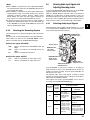
2-5
Menu Operation Section
2
MENU button
Used to turn on/off the menu.
JOG dial button
With the menu open, this button is used to navigate through
menu pages, select options and specify values.
For directions on manipulating the menu, see [4-6 Menu
Displays in the Viewfinder Screen].
SD card insertion slot
An SD card (optional accessory) is inserted here.
BUSY (operation mode display) lamp
This lamp indicates the active status of the SD card.
It stays illuminated when the card is active.
<Note>
While the lamp is on, do not insert or remove the card.
17
2-6
Time Code Section
GENLOCK IN connector (BNC)
TCG (time code selector) switch
This connector is used to input a reference signal before the
camera unit is gen-locked, or before the time code is
externally locked.
This switch is used to specify the stepping mode for the
built-in time code generator.
TC IN connector (BNC)
This connector is used to input a reference time code when
you externally lock the time code.
TC OUT connector (BNC)
When you inter-lock the time code of the AJ-SPX900E with
that of an external device this must be connected with the
time code input (TC IN) connector of the external device.
F-RUN: Select this position to continuously advance the
time code independently of the P2 card recording
status.
Use this mode to synchronise the time code with
the time of day, or to externally lock the time code.
SET:
Select this position to set the time code and/or
user bits.
R-RUN: Select this position to advance the time code only
during recording.
For spliced scenes recorded on P2 cards, the
sequence of time codes is unbroken.
HOLD button
Pressing this button freezes the time data indication on the
counter. Note that time code generation continues. Pressing
the button again reactivates the counter.
This function is used to ascertain the time code of a
particular recorded scene.
RESET button
This button resets the time data on the counter to
“00:00:00:00”.
If this button is pressed when with the
TCG switch
positioned at [SET], CTL* data, time code data, user bit
data, and real-time data are reset to 0. Real-time data is
also reset to the defaults.
DISPLAY (counter display selector) switch
Indications of the time code, CTL* and user bits on the
counter of the display window depend on the positions of
this switch and the
TCG switch.
Pressing the
HOLD button also displays Date/Time/Time
Zone.
UB:
TC:
CTL*:
User bits indicated.
Time code indicated.
CTL indicated.
* CTL will be supported in the near future.
18
CURSOR and SET buttons
Use these buttons to set the time code and user bits.
The four triangular buttons are the CURSOR buttons, and
the center rectangular one is the SET button.
For guidance in setting the time code and user’s bit, see [4-5
Setting Time Data].
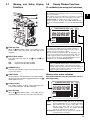
2-7
Warning and Status Display
Functions
2-8
Display Window Functions
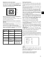
P2 card/battery-remaining level indications
Media-remaining space indication bar
The bar indicates the remaining free space on each P2 card, using a
seven-segment display.
Each segment can represent either three or five minutes of remaining
free space, depending on the value set through the menu option
CARD REMAIN/. According to the set value, the segments
disappear one-by-one. The menu option CARD REMAIN / can be
found in the <BATTERY/P2CARD> screen on the MAIN OPERATION
page.
SLAVE HOLD W DV GPS
CTL VTCG TIME DATE P- REC
OVER
OVER
0
10
h Y
minM
s D
MEDIA E
BATT E
frm
20
F
30
F
40
OO
LOOP
Back tally lamp
When the
BACK TALLY switch is set to [ON], the lamp
behaves in the same way as the front tally lamp at the
viewfinder.
BACK TALLY switch
This switch controls the action of the
tally lamps.
ON:
OFF:
back and
rear
Back and rear tally lamps enabled.
Back and rear tally lamps disabled.
WARNING lamp
This lamp starts blinking or lights up if something unusual
occurs in the memory.
LIGHT button
Use this button to control illumination of the display window.
Alternately pressing this button toggles illumination of the
display window on or off.
Display window
This window displays warnings, battery-remaining level,
sound volume, time data, and other information.
Rear tally lamp
When the
BACK TALLY switch is set on [ON], the rear
tally lamp behaves in the same way as the back tally lamp.
DRIVE
OP-SLOT
13
-dB
24
Battery-remaining level indication bar
For a battery with a digital indicator (percentage indication), if
the remaining level of the battery is higher than 70%, all seven
segments up to the “F” position are lighted.
When the remaining level falls below 70%, the segments go out
one-by-one for each drop of 10%. All seven segments can be set
to light up when the battery-remaining balance is 100%. To do
so select “100%” for the menu option BATT REMAIN FULL in the
P2CARD> screen of the MAIN OPERATION page.
Audio channel level meter
When the MONITOR SELECT CH1/2 / CH3/4 switch is set to
[CH1/2], the meter indicates 1 and 2 as the audio channel
numbers, together with their audio levels. When the switch is set
to [CH3/4], the meter indicates 3 and 4 as the audio channel
numbers, together with their audio levels.
Memory action status indication
Error Code Indication (for more information, see [7-3
Warning System])
SLAVE HOLD W DV GPS
CTL VTCG TIME DATE P- REC
OVER
OVER
0
10
h Y
minM
MEDIA E
BATT E
s D
frm
20
F
30
F
40
OO
LOOP
DRIVE
OP-SLOT
13
-dB
24
Information indication
LOOP:
Stays illuminated in LOOP REC mode. For information
about the LOOP REC mode, see [4-5 Setting Time Data].
DRIVE: Stays illuminated when the menu option USB is set to
“ON”.The menu option USB can be found in the
<SYSTEM MODE> screen on the SYSTEM SETTING
page. (To be supported in the near future.)
OP-SLOT: Stays illuminated when the optional slot is available. (To
be supported in the near future.)
19
2
2-9
LCD Monitor
Mode indication
W:
Stays illuminated in 16:9 mode.
DV:
Stays illuminated when the recording/playback format is
DV.
GPS:
Stays illuminated when radio waves are not received
during GPS operation.
GPS : Stays illuminated when radio waves are received during
GPS operation.
P-REC: Stays illuminated when PRE RECORDING is not set to 0
seconds, and blinks when recording is continued after the
recording tally lamp has gone out.
SLAVE HOLD W DV GPS
CTL VTCG TIME DATE P- REC
OVER
OVER
0
10
h Y
minM
s D
frm
MEDIA
BATT E
E
20
F
30
F
40
OO
LOOP
DRIVE
OP-SLOT
13
-dB
24
Time code indication
SLAVE: Stays illuminated when the time code is externally locked.
HOLD:
Stays illuminated when the time code generator/reader
value is frozen.
CTL*:
Stays illuminated when the DISPLAY switch is positioned
at [CTL] to display the CTL count.
TCG:
Stays illuminated when the DISPLAY switch is positioned
at [TC] (or [UB]) to display the TC (or UB) generator value.
TC:
Stays illuminated when the DISPLAY switch is positioned
at [TC] (or [UB]) to display the TC (or UB) reader value.
VTCG:
Stays illuminated when the DISPLAY switch is positioned
at [UB] to display the VIUB generator value.
VTC:
Stays illuminated when the DISPLAY switch is positioned
at [UB] to display the VIUB reader value.
TIME:
Stays illuminated when the DISPLAY switch is positioned
at [UB] to display the real-time hour, minute and second.
DATE:
Stays illuminated when the DISPLAY switch is positioned
at [UB] to display the real-time date.
No Indication:
The CTL, VTGC, TIME, and DATE stay off when the
DISPLAY switch is positioned at [UB] to display real time,
time zone, hour and minute.
Time count indication:
The time code, CTL*, user bits and real time are shown.
* CTL will be supported in the near future.
<Note>
When the DISPLAY switch is positioned at UB, each press of the
HOLD button changes the indication through VTCG (VTC) DATE
TIME No Indication (Time Zone) TCG (TC), in that order.
20
LCD monitor
The LCD monitor displays the video in the viewfinder.
Alternatively, it can show clips on the P2 card in a thumbnail
format.
In thumbnail display mode, clips can be edited or deleted, or
P2 cards can be formatted using the
MENU BAR button
and
CURSOR and SET buttons.
OPEN button
Used to open the LCD monitor.
THUMBNAIL button
This button switches the content on the
LCD monitor
from the video in the viewfinder to clip thumbnails. Another
press switches them back to the video from the viewfinder.
Note that this switchover is not performed during a recording
or playback.
MENU BAR button
In thumbnail display mode, this button allows you to
manipulate the menu bar (e.g., to delete clips).
CURSOR and SET buttons
The four triangular buttons are the CURSOR buttons, and
the center rectangular one is the SET button.
They are used to select a thumbnail and manipulate the
menu bar. For more information, see [Chapter 6
Manipulating Clips with Thumbnails].
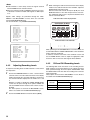
2-10
Viewfinder
Back tally lamp
This lamp stays illuminated during shooting. It also blinks in
synchronisation with the REC lamp in the viewfinder, and
provides alerts.
When the lever is positioned at [OFF], the back tally lamp is
hidden.
Eyepiece
Diopter adjustment ring
Use this to make adjustments in line with your diopter, in
order to obtain optimum clarity in the viewfinder image.
Viewfinder (optional accessory)
During recording or playback, the viewfinder displays the
video image in monochrome. It also displays warnings,
messages, zebra patterns, markers (safety zone and center
markers), etc.
ZEBRA (zebra pattern) switch
This switch is used to display the zebra pattern in the
viewfinder.
ON:
OFF:
Connecting plug
Locking ring
Microphone holder
Viewfinder stopper
Used to attach or remove the viewfinder.
Zebra pattern displayed.
No zebra pattern displayed.
TALLY switch
Used to control the
HIGH:
OFF:
LOW:
front tally lamp.
Front tally lamp brightly illuminated.
Front tally lamp stays off.
Front tally lamp dimly illuminated.
PEAKING control
Used to adjust the outlines of the video image in the
viewfinder for easier focusing. This does not affect the signal
output from the camera.
CONTRAST control
Used to adjust the contrast of the video image in the
viewfinder. This does not affect the signal output from the
camera.
BRIGHT control
Used to adjust the brightness of the video image in the
viewfinder. This does not affect the signal output from the
camera.
Front tally lamp
Viewfinder left-right position anchoring ring
Used to adjust the side-to-side position of the viewfinder.
Viewfinder front-back position anchoring lever
Used to adjust the fore-and-aft position of the viewfinder.
<Note>
For more information, see the instruction manual for the
viewfinder.
This lamp is activated when the
TALLY switch is
positioned at [HIGH] or [LOW], and stays on during
recording. It also blinks in synchronisation with the REC
lamp in the viewfinder, and provides alerts.
Use the TALLY switch to change the intensity of the lamp to
([HIGH] or [LOW]).
21
2
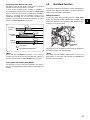
Chapter 3 Recording and Playback
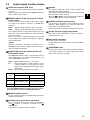
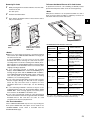
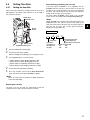
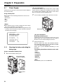
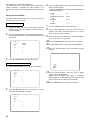
3-1
P2 Cards
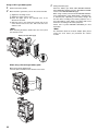
Inserting P2 Cards
3
<Note>
Insert a P2 card into the P2 card slot until the EJECT button
pops up.
When using the camera-recorder for the first time, be sure to set
the time data beforehand. On how the time data is set, see [4-5
Setting Time Data].
1
Turn on the POWER switch.
EJECT button
The card must be
inserted with the
logo right way up.
4
POWER: ON
2
Tilt up the popped-up EJECT button, to lock-in the P2 card.
P2 card
LED
While pressing down the slide lock button, slide the slideout door to the left.
The door opens.
Slide lock
button
Slide-out door
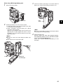
5
6
Insert a P2 card into the AJ-SPX900E. The P2 CARD
ACCESS LED for the appropriate slot indicates the status
of the P2 card.
For how the P2 card status is indicated, see [P2 CARD
STATUS LED and status of P2 cards] on the next page.
Close the slide-out door.
<Note>
Do not leave the slide-out door open when moving the AJSPX900E.
22
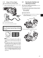
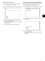
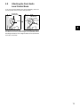
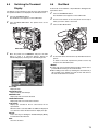
Removing P2 Cards
To Prevent Accidental Erasure of P2 Card Content
1
To prevent the content of a P2 card being accidentally erased,
position the write-protect switch on the P2 card at [Pprotect].
2
3
While pressing down the slide lock button, move the slideout door to the left.
The door opens.
Tilt down the EJECT button.
Then, depress the EJECT button to release the P2 card so
that you can remove it.
<Note>
Write-protect switchover can be performed while the card is
being accessed (during recording or playback), but does not
take effect until access to the card ceases.
3
Protect
Write-protect switch
P2 CARD STATUS LED and status of P2 cards
Tilt down the EJECT
button.
Depress the tilted-down
EJECT button to release
the P2 card.
<Notes>
z When a P2 card is being accessed or it is being recognised
after insertion (P2 CARD ACCESS LED blinks in orange), do
not remove the P2 card.
If your AJ-SPX900E is not set to turn on the P2 CARD
ACCESS LED, before removing the card ensure that prerecording and/or voice memo recording have finished (the PREC indication has stopped blinking and the V mark or VOICE
REC indication on the viewfinder screen has turned off) after
stopping recording or playback.
z If a P2 card being accessed is removed, the viewfinder
displays “TURN POWER OFF” and the AJ-SPX900E gives a
warning using an alarm and the WARNING LED. In addition,
all P2 CARD ACCESS LEDs blink rapidly in green. If this is the
case, turn the power off. For more information on warning
indications, see “7-3 Warning System”.
z If a P2 card is removed while being accessed, clips on it may
become irregular although the data will not be corrupted.
Check the clips and restore them if required. For more
information about how to restore clips, see “6-9 Restoring
Clips”.
z If a P2 card being formatted is removed, it may be not be
formatted properly. In this case, the viewfinder displays “TURN
POWER OFF”. If this message appears, turn off the power,
then restart the AJ-SPX900E to reformat the card.
z If a P2 card is inserted while another P2 card is being played
back, the inserted P2 card is not recognised and the P2 CARD
ACCESS LED for that card does not come on. Card
recognition starts when the playback ends.
P2 CARD
STATUS LED
MODE CHECK
indication*
Status of P2 Card
Stays on in green ACTIVE
Writing and reading enabled
Stays on in
orange
ACTIVE
Writing and reading enabled.
The card is recordable (loop
recording also enabled).
Stays on in
orange or green
ACTIVE !
Writing and reading enabled.
However, some clips
recorded on the P2 card may
not be able to be read
successfully.
Blinks in orange
ACCESSING
Writing or reading being
performed.
Quickly blinks in
green
INFO READING
The P2 card is being
recognised.
FULL
The P2 card has no free
space. Only reading is
enabled.
PROTECTED
The write-protect switch on
the P2 card is positioned at
[PROTECT]. Only reading is
enabled.
NOT
SUPPORTED
The card is not supported by
your AJ-SPX900E. Replace
the card.
FORMAT ERROR
The P2 card is not properly
formatted. Reformat the
card.
NO CARD
No P2 card is inserted.
Blinks in green
Stays off
* The mode check indication is shown in the viewfinder. For more
information, see [4-7-2 Viewfinder Status Indication Layout].
<For Your Information>
The P2 CARD ACCESS LEDs may be set to stay off using the
menu option ACESS LED. This option can be found on the
<SYSTEM MODE> screen, which is accessible from the
SYSTEM SETTING page.
23
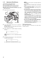
3-2
Basic Procedures
This section describes the basic procedure for shooting and
recording.
Before you embark on a shoot, pre-inspect your system to
ensure that it works properly.
* For directions on inspecting your video camera-recorder, see [7-1
Inspections Before Shooting].
3
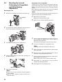
Insert a charged battery pack.
When a battery and P2 cards are installed, set the switches as
detailed below, before starting to use your AJ-SPX900E.
Turn on the POWER switch and ensure that more than four
segments of the battery-remaining amount indication bar
are illuminated.
z If the number of illuminated segments is fewer than five,
first check the battery placement. If placement is not the
problem, replace the battery with a fully charged one.
Insert a P2 card and ensure that the P2 CARD STATUS
LED stays on in orange or green. Then, close the slide-out
door.
When more than one P2 card slot contains a P2 card, the
card in the slot with the lowest number is used first.
However, regardless of slot number, a P2 card inserted
later will not be accessed until the other cards have been
used.
Example:
If all five slots contain P2 cards, the cards are used in order
of slot numbers 12345. However, if the P2 card in
Slot 1 is removed and then re-inserted, the cards will be
used in the following order: 23451.
2
2
1
3
5 4 3 2 1
24
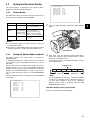
Switch Setting
Setting the switches before shooting and recording
USER MAIN:
AUDIO SELECT
This switch is factory-set to perform
CH 1/CH 2:
slot selection.
AUTO
Battery Set-up to P2 card Insertion
1
2
Note that the recording order is retained even if the power is
turned off. When the power is next turned on, the last card
written before powering-down will be the target card.
TCG:
F-RUN or
R-RUN
OUTPUT:
CAM/AUTO KNEE ON
Iris: Auto
GAIN:
Normally, this should be set to 0 dB. If
conditions are too dark, an appropriate
gain level should be set.
<Note>
The USER MAIN button is factory-set to perform the slot
selection function, which selects the target card from among
several P2 cards.
When a new target P2 card is selected, the appropriate slot
number appears on the P2 card remaining amount indicator in
the viewfinder.
For more information about the indications in the viewfinder, see
[4-7-2 Viewfinder Status Indication Layout].
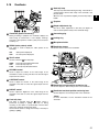
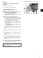
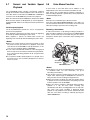
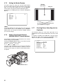
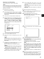
Shooting
White/Black balance adjustment to recording completion
White/Black Balance Adjustment to Recording
Completion
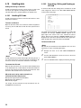
For shooting, follow the steps below.
1 Select a filter according to light conditions.
2A When the white balance is saved:
3
Position the WHITE BAL switch to [A] or [B].
2B When the white or black balance is not saved and you
have no time to adjust the white balance:
Position the WHITE BAL switch to [PRST].
This adjusts the white balance against the filter according
to the position of the FILTER control.
3
1
4 5, 6 2C
2A, B, C
2C If the white balance is adjusted on the spot:
Select a filter according to light conditions. Then, position
the WHITE BAL switch to [A] or [B] and shoot a white test
subject so that it appears at the center of the screen. Then,
follow the steps below to adjust the white balance.
1. Press the AUTO W/B BAL switch toward [AWB] to adjust
the white balance.
2. Press the AUTO W/B BAL switch toward [ABB] to adjust
the black balance.
3. Press the AUTO W/B BAL switch toward [AWB] to adjust
the white balance again.
For directions on making adjustments, see [4-1-1 Adjusting
the White Balance] and [4-1-2 Adjusting the Black
Balance].
3
4
5
6
Point the camera at your subject to adjust the focus, and
zoom.
To use the electronic shutter, set the shutter speed and
operation mode.
For more information, see [4-2 Setting the Electronic
Shutter].
Press either the REC START/STOP button, REC button on
the handle or VTR button at the lens to start recording.
During recording, the REC lamp in the viewfinder stays
illuminated.
To stop recording, press either the REC START/STOP
button, REC button on the handle or VTR button at the lens.
The REC lamp in the viewfinder goes out.
Operation Buttons
During recording, all operation buttons (REW, FF, PLAY/
PAUSE, STOP) are disabled.
25
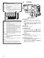
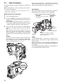
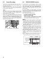
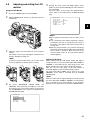
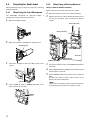
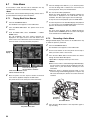
3-3
Normal Recording
Pressing either the REC START/STOP button, REC button on
the handle or VTR button at the lens starts recording of video
and sound on the P2 card.
A cluster of data that consists of video and sound generated
through a shooting action, together with such added information
as a voice memo, is called a “clip”.
<Note>
Even if a P2 card has just been inserted, or the power has been
just turned on, you can start recording using the internal
memory of the AJ-SPX900E. In this case, recording cannot be
stopped until the P2 card is recognised.
However, if the AJ-SPX900E determines that the inserted P2
card is non-recordable, the data in the internal memory will be
deleted, with the message “CANNOT REC” appearing on the
viewfinder screen. In this case, press the MODE CHECK button
to check the status of the P2 CARD via the P2 CARD STATUS
indication on the viewfinder screen.
Rec start/stop button
Mode check button
3-4
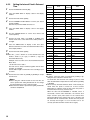
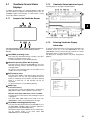
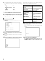
PRE-RECORDING function
The internal memory of your AJ-SPS800 is capable of storing
several seconds of video and sound data coming from the
camera. This capability can be used to record video and sound
several seconds before either the REC START/STOP button,
REC button on the handle or VTR button at the lens is pressed
to start recording.
To use this capability, the storage duration of the internal
memory must be set through the menu option PRE REC TIME.
This option can be found in the <REC FUNCTION> screen on
the SYSTEM SETTING page.
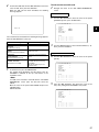
These are the options for PRE REC TIME.
0-15 SEC (for DVCPRO 25M or DV)
0-8 SEC (for DVCPRO 50M):
Specify the duration for which data may be recorded
before either the REC START/STOP button, REC button
on the handle or VTR button at the lens is pressed.
<Notes>
z Immediately after the power is turned on, the menu option
PRE REC TIME is selected and/or the storage duration is
changed, the content in internal memory will be undefined. In
these situations, the video or sound will not be recorded for
the duration specified, even if either the REC START/STOP
button, REC button on the handle or VTR button at the lens is
pressed to start recording.
z A P2 card that has been just inserted takes some time to
recognise. In this situation, video or sound may not be
recorded for the duration specified, even if either the REC
START/STOP button, REC button on the handle, or VTR
button at the lens is pressed to start a recording.
z The internal memory does not store video or sound when a
playback or recording review is being performed. For this
reason, no video or sound can be recorded during such
operation.
z When recording starts, the time code indication (TCG) may be
shown as “HOLD” until the P2 card has been recognised.
REC start
(Recording starts)
Real-time video
Real-time sound
A
REC/PAUSE
(Recording pauses)
B
C
Specified PRE-REC
duration
Content on P2 card Previous clip
A
B
New clip
26
3-5
Loop Recording
3-6
When two or more P2 card slots contain cards, this function
allows the target P2 card to be switched in order. Even when the
free space of a P2 card is used up, this function continues
recording while erasing existing data.
To use this function, the menu option LOOP REC MODE must
be set to “ON” The option LOOP REC MODE can be found in
the <REC FUNCTION< screen on the SYSTEM SETTINGS
page.
Card1
Before loop
recording starts
No content
Card2
Card3
Content
recorded
Recording starts
Recording Cycle 1
Recording Cycle 2
A
D
B
C
B
C
Recording Review Function
When recording is paused, pressing the RET button
automatically locates the last two seconds of video just
recorded, and the viewfinder provides video playback.
After playback, the video camera-recorder is again ready to start
recording.
The picture location/playback duration can be increased to up to
10 seconds by continuously pressing the RET button. For short
clips, however, when the start of a clip is located, continuously
pressing the RET button does not play back any clips before that
clip.
The function of the RET button may be assigned to a desired
user button by using one of the menu options USER MAIN SW,
USER1 SW or USER2 SW. These options can be found in the
<USER SW> screen on the CAM OPERATION page.
When recording is paused, pressing the PLAY/PAUSE button
plays back the last recorded clip, from the beginning. After
completion of playback, the camera-recorder enters the stopped
state.
<Note>
The data is recorded in the free space of each P2 card (in order of A
B C). When the free space is used up, the content on A is
erased to perform a new recording on D.
<Note>
z When the loop recording capability is used, each P2 card must
have at least one minute of free space.
z During loop recording, the P2 CARD ACCESS LEDs for all
target P2 cards illuminate in orange. Note that if any of the
target P2 card is removed, loop recording stops.
z When the menu option LOOP REC MODE is set to ON, the
viewfinder and display window both show “LOOP”.
However, when only one card is inserted, or when each card
has less than one minute of free space, the loop recording
capability does not work, even if the option LOOP REC MODE
is set to ON. If this is the case, the indication “LOOP” flashes
in the viewfinder and on the display window.
When the OUTPUT SEL switch on the side panel is positioned
at [MEM], the video for REC REVIEW is output from the video
output connectors (VIDEO OUT and MON OUT connectors),
and also to the viewfinder.
Note that when a backup device is connected to back up the
video the pictures for REC REVIEW are backed up.
Recording starts
Recording pauses
2-10 Seconds
Recorded clip
The PLAY button plays back
the clip from the beginning.
The RET button puts
the video camerarecorder into REC
REVIEW mode.
Terminating the Loop Recording Mode
You can terminate the loop recording mode by either:
z Turning off the POWER switch of the AJ-SPX900E; or
z Setting the menu option LOOP REC MODE to “OFF”.
27
3
3-7
Normal and Variable Speed
Playback
The PLAY/PAUSE button provides monochrome playback
through the viewfinder and color playback on the LCD monitor. A
color video monitor connected to the VIDEO OUT or MON OUT
connector of the AJ-SPX900E also provides color playback.
When the extension board AJ-YA902AG is attached, the VIDEO
OUT connector outputs an SDI playback (to view the playback,
the OUTPUT SEL switch on the side panel must be positioned to
[MEM]).
3-8
Voice Memo Function
A voice memo is voice data which can be added to a clip
independently of the normal sound data recorded in the clip.
Voice memos may recorded during recording or playback, or
when recording or playback is paused. They can be played back
in thumbnail display mode.
<Note>
Each clip can accommodate up to 100 voice memos.
If the menu option VOICE MEMO RESERVE is set to “ON”, you
can record at least 10 minutes of voice memos for each P2 card
while clip recording is paused or after recording ends.
Variable speed playback
The FF and REW buttons provide 32C and 4C fast playbacks
and fast reverse playbacks.
When playback is paused, the FF button locates the beginning
of the next clip while maintaining the pause mode.
When playback is paused, the REW button locates the
beginning of the current clip while maintaining the pause mode.
Recording a Voice Memo
To add a voice memo to a clip during recording or playback, or
when recording or playback is paused, press the VOICE MEMO
button. A voice memo may be recorded using the voice memo
microphone. Another press of the button stops recording of the
voice memo.
<Notes>
z When a P2 card has been just removed or inserted, or when
the power has been just turned on for playback, it may take
some time for the AJ-SPX900E to read clip information. If this
is the case, the viewfinder displays “UPDATING”.
z If a P2 card is inserted while another P2 card is being played
back, the clips on the inserted P2 card will not be played back.
A P2 card inserted during playback will be recognised after
playback ends.
z If you perform variable speed playback on a clip split across
more than one P2 card, sound may disappear for a moment.
This is not a fault.
Voice memo
microphone
VOICE MEMO button
<Notes>
z Voice memos can also be recorded when the LCD monitor is
in thumbnail mode. For more information, see [6-7-2
Recording a Voice Memo].
z Voice memos cannot be recorded when color bars are being
output, video input through the GENLOCK IN connector is
being recorded, or loop recording is being performed.
z During voice memo recording, turn down the speaker volume
to prevent the voice memo microphone from picking up sound
from the speakers of the AJ-SPX900E.
z When voice memo recording is performed during recording/
playback of a clip, the voice memo recording also
automatically ends when recording/playback of the clip ends.
Also, when voice memo recording is performed during
playback of a clip, playback of the clip also automatically ends
when the voice memo recording is ended by pressing the
VOICE MEMO button.
28
Associating Voice Memos with a Clip
The portion of the clip with which a voice memo is associated
depends on when the voice memo is recorded.
A voice memo recorded during recording or playback is
associated with the picture in view at the time the VOICE MEMO
button is pressed. A voice memo recorded when recording is
paused is associated with the beginning picture of the
immediately preceding clip. A voice memo recorded when
playback is paused is associated with the still picture in view at
the time the VOICE MEMO button is pressed.
Recording or
playback
Recording
paused
Playback
paused
3-9
Shot Mark Function
A shot mark is added to the thumbnail of a clip to distinguish that
clip from others. With the LCD monitor, only clips that have shot
marks can be viewed and/or played back.
Adding Shot Marks
To add a shot mark during recording, press the SHOT MARK
button. The viewfinder displays “MARK ON” and adds a shot
mark to the thumbnail of the appropriate clip. Another press of
the button erases the shot mark.
Clip being recorded
Recorded clip
Clip being played back
SHOT MARK
button
Voice memo
Voice memo recording starts
Shot marks may also be added or erased using clip thumbnails.
For more information, see [6-6 Shot Mark].
<Note>
<Note>
When, with PRE RECORDING executed, a voice memo is
recorded, the voice memo may be associated with a picture in
view prior to point when the VOICE MEMO button is pressed.
Shot marks cannot be added or deleted when color bars are
being output, or when video input through the GENLOCK IN
connector is being recorded.
Playing Back and Deleting Voice Memos
For information on how to play back and delete voice memos,
see [6-7-1 Playing Back Voice Memos] and [6-7-3 Deleting Voice
Memos].
29
3
Chapter 4 Adjustments and Settings for Recording
To record high-quality video with the AJ-SPX900E, the black and
white balances must be adjusted according to conditions.
For higher quality, it is recommended that the adjustments
should be made in this order AWB (white balance adjustment)
ABB (black balance adjustment) AWB (white balance
adjustment).
4-1
4-1-1
3
Adjusting the White balance
and Black Balance
Place a white pattern at a point where the light conditions
match those for the light source of the subject. Then zoomin on the white pattern so that white color appears in the
screen. A white object (cloth or wall) may be used instead
of a white pattern.
The illustration below shows the required size for the white
space.
<Note>
z Do not include a high-intensity spot in the screen.
z The white object must appear at the center of the screen.
Adjusting the White Balance
1/4 or more of the screen in width
Whenever light conditions change, the white balance must be readjusted.
To adjust the white balance, follow the steps below.
1
1/4 or more of the
screen in height
Set the switches as illustrated below.
CC FILTER/ND FILTER controls
4
5
Adjust the lens iris.
Flip up the AUTO W/B BAL switch so that it is positioned at
[AWB], then release it.
The switch returns to the central position with the white
balance automatically adjusted.
<Notes>
To cancel automatic white balance adjustment in process
(the viewfinder displays “AWB ACTIVE”), re-position the
AUTO W/B BAL switch at [AWB].
If automatic adjustment is canceled, the value in effect
before automatic adjustment will be used.
WHITE BAL: A or B
AUTO W/B BAL
switch:
Used to perform AWB.
2
6
OUTPUT: CAM
GAIN:Under normal conditions, set to 0 dB
If it is too dark, an appropriate gain
should be set.
Adjust the CC FILTER/ND FILTER controls according to the
light conditions.
During an adjustment, the viewfinder displays the following
message:
ޓޓޓޓޓޓޓޓޓޓޓޓޓޓ$:%$&7,9(
7
<Note>
For examples of CC FILTER/ND FILTER adjustments, see
[2-4 Shooting and Recording/Playback Functions Section].
The adjustment will take effect in a few seconds, and the
following message will appear:
The adjusted value is automatically stored in the memory
specified in Step 1 ([A] or [B]).
ޓޓޓޓޓޓޓޓޓޓޓޓޓޓ$:%$2..
8
For the 3200K CC filter, if the subject’s color temperature is
lower than 2300K or higher than 9900K the following
message appears:
If the arrow points down () the actual color temperature is
lower than the temperature indicated. If the arrow points up
() the actual temperature is higher than the temperature
indicated.
ޓޓޓޓޓޓޓޓޓޓޓޓޓޓ$:%$2..
30
Detection area for the white balance
Retaining white balances
The detection area for the white balance is selectable between
90%, 50% and 25%, using the menu option AWB AREA.
This option can be found in the <WHITE BALANCE MODE>
screen, which is accessible from the CAM OPERATION page.
The detection area is factory-set to 25%.
Each value in memory is retained even if the video camerarecorder is turned off; it will not be lost until the white balance is
re-adjusted. White balances are stored in either of two systems:
A or B.
When the menu option FILTER INH is set to “ON” (default), each
system stores only one value. If this is the case, the values are
not synchronised with the CC filter.
This option can be found in the <WHITE BALANCE MODE>
screen, which is accessible from the CAM OPERATION page.
When the menu option FILTER INH is set to “OFF”, the adjusted
value for each CC filter can be automatically stored in the
memory that corresponds to the position of the WHITE BAL
switch (A or B). Your AJ-SPX900E has four built-in CC filters; it
stores eight (4 C 2) adjusted values.
Note that, when the menu options AWB A and AWB B are set to
“VAR”, the color temperatures specified through COLOR TEMP
A and COLOR TEMP B are used, meaning that the white
balances cannot be adjusted with the AWB switch. The menu
options are found in the <WHITE BALANCE MODE> screen,
which is accessible from the CAM OPERATION page.
90%
50%
25%
When you have no time to adjust the white balance:
Position the WHITE BAL switch at [PRST].
This adjusts the white balance for the filter according to the
position of the FILTER control (outer).
Setting the auto-tracking white balance (ATW)
When the white balance has not been automatically
adjusted:
When the white balance has not been successfully adjusted, the
viewfinder displays an error message.
If one of the error messages listed below appears, take the
appropriate steps, then adjust the white balance again.
If the error message appears after repeated readjustments, the
interior of the unit must be inspected. For more information,
contact a service center or your distributor.
Error message
Description
Remedies
COLOR TEMP.
HIGH
The color
temperature is too
high.
Select an appropriate
filter.
COLOR TEMP.
LOW
The color
temperature is too
low.
Select an appropriate
filter.
LOW LIGHT
There is insufficient
light.
Increase the light level or
gain.
LEVEL OVER
There is too much
light.
Decrease the light level or
gain.
CHECK FILTER
The FILTER control
is displaced.
Check the FILTER
control.
TIME OVER
AWB was not
completed within
the time allowed.
Shooting conditions may
be unstable. If flicker
occurs, press the shutter
and readjust the AWB
under stable conditions.
The AJ-SPX900E has an auto-tracking white balance (ATW)
feature that automatically tracks the white balance for pictures
according to lighting conditions.
The ATW feature can be assigned to Position [B] of the WHITE
BAL switch. To do so, the menu option AWB B must be set to
“ATW”. This option can be found in the <WHITE BALANCE
MODE CAM> screen, which is accessible from the CAM
OPERATION page.
The ATW feature may be assigned to the USER MAIN, USER1,
or USER2 button. For more information, see [4-9-4 Assigning
Functions to USER MAIN, USER1 and USER2 Buttons].
To cancel the auto-tracking white balance:
Press the user button that has the ATW feature assigned, or
change the position of the WHITE BAL switch. Note that, when
the ATW feature is assigned to [B] of the WHITE BAL switch, the
auto-tracking white balance cannot be canceled with a user
button.
:+,7(%$/$1&(02'(!
),/7(5,1+21
6+2&./(66$:%1250$/
$:%$5($
$:%$%%2))6(72))
&2/257(0335(.
$:%$0(0
&2/257(03$.
$:%%0(0
&2/257(03%.
$7:63(('1250$/
<Note>
This function does not guarantee 100% accuracy of the white
balance.
When using the AJ-SPX900E, remember that there will be some
allowance in the trackability of changes in lighting conditions and
pull-in accuracy of white balances.
Viewfinder displays related to white balance
See [4-7 Viewfinder Screen Status Displays].
31
4
4-1-2
Adjusting the Black Balance
The black balance must be adjusted when:
z You use your AJ-SPX900E the first time;
z Your AJ-SPX900E has not been used for some time;
z The ambient temperature has changed substantially;
z The gain switchover value has been changed; or
z S.GAIN (super gain) has been set with the USER MAIN/
USER1/USER2 button.
1
Set the switches as illustrated below.
AUTO W/B BAL switch:
Used to perform ABB.
2
3
OUTPUT: CAM
During adjustment, the viewfinder displays the following
message:
<Note>
During adjustment, the lens iris automatically becomes
CLOSE.
The adjustment will take effect in a few seconds and the
following message will appear:
ޓޓޓޓޓޓޓޓޓޓޓޓޓޓ$%%2.
The adjusted value is automatically stored in the memory.
32
z Ensure that the lens connector is connected and the lens
iris is CLOSE.
z During a black balance adjustment, light is automatically
cut off.
z During a black balance adjustment, the gain switchover
circuit is automatically switched.
The viewfinder screen may flicker and/or display noise;
this is not a failure.
z If you find the black shading annoying after performing an
auto black balance adjustment, adjust the black shading.
To do so, go to the menu option DETECTION, move the
cursor (), then press the JOG dial button. The menu
option DETECTION can be found in the <BLACK
SHADING> screen, which is accessible from the
MAINTENANCE page.
Note that pressing the ABB switch for longer than five
seconds automatically performs an auto black balance
adjustment, followed by an automatic black shading
adjustment. (For more information, see the menu option
SHD. ABB SW CTL in [8-5-5 SW MODE].)
z To cancel the automatic black balance adjustment in
process (the viewfinder displays “ABB ACTIVE”), flip the
AUTO W/B BAL switch down to [ABB] again.
If automatic adjustment is canceled, the value in effect
before automatic adjustment will be used.
Retaining black balances
Tilt the AUTO W/B BAL switch so that it is positioned at
[ABB], then release it.
The switch returns to the central position with the black
balance automatically adjusted.
ޓޓޓޓޓޓޓޓޓޓޓޓޓޓ$%%$&7,9(
4
<Notes>
Each value in memory is retained even if the video camerarecorder is turned off.
4-2
Setting the Electronic Shutter
6+877(56(/(&7!
This section provides a description of the electronic shutter,
together with setting and handling directions.
4-2-1
683(5902'()50
326,7,216(/
326,7,216(/
326,7,216(/
326,7,216(/
326,7,216(/
326,7,216(/
Shutter Modes
The table below shows the shutter modes and speeds for the
electronic shutter provided in your AJ-SPX900E.
Mode
Shutter speed
Application
Normal
POSISTIONS 1-6
Used to capture clear images
of a fast-moving subject
SYNCHRO
SCAN
Range of 50.4 Hz
to 248.0 Hz (50i)
Used to reduce the effect of
horizontal lines when
shooting a monitor screen
that has a vertical scanning
frequency of more than 50 Hz
Range of 25.0 Hz
to 248.0 Hz (25P)
SUPER V
1
Press the SHUTTER switch, positioned at [ON], towards
[SEL].
Used to enhance vertical
resolution
<Notes>
z In any mode, the higher the shutter speed the lower the
sensitivity of the camera.
z When the iris is automatically adjusted, the higher the shutter
speed the larger the iris, and the shorter the depth of focus.
SHUTTER switch
4-2-2
Setting the Shutter Mode and Speed
The shutter speed in any shutter mode is set using the
SHUTTER switch.
In SYNCHRO SCAN mode, shutter speed can be switched
easily, using the synchro-scan adjustment switches (+/–) on the
side panel.
Note that the range of selectable shutter speeds may be predefined; whether or not to use the SYNCHRO SCAN and
SUPER V modes may be determined through the <SHUTTER
SPEED> and <SHUTTER SELECT> screens. These screens
are accessible through the menu on the CAM OPERATION
page.
The selected shutter speed is retained even if the AJ-SPX900E
is turned off.
6+877(563(('!
6<1&+526&$121
683(592))
326,7,2121
326,7,2121
326,7,2121
326,7,2121
326,7,2121
326,7,2121
2
Once more, press the SHUTTER switch towards [SEL].
Repeat this switchover until the desired mode or speed
appears in the viewfinder screen.
If all modes and speeds are available, the display changes
in the following order:
NORMAL mode
1/60
1/120
SUPER V
mode
1/250
1/500
1/1000
1/2000
SYNCHRO
SCAN mode
<Note>
Your AJ-SPX900E is not factory-set to display the SUPER
V mode on the viewfinder screen. To display this mode, set
the menu option SUPER V found in the <SHUTTER
SPEED> screen, which is accessible from the CAM
OPERATION page, to “ON”.
Viewfinder displays relating to the shutter
See [4-7 Viewfinder Screen Status Displays].
33
4
4-2-3
Placing the Camera-recorder in
SYNCHRO SCAN Mode
To place the camera-recorder in SYNCHRO SCAN mode, follow
the steps below.
1
Press the SHUTTER switch positioned at [ON] towards
[SEL], to place the camera-recorder in SYNCHRO SCAN
mode.
SYNCHRO SCAN ADJUSTMENT buttons (+/–)
4-3
Selecting Recording Signals
and Recording System
The AJ-SPX900E is capable of utilising user-selected recording
signals and format.
4-3-1
Selecting the Recording Signals.
Signals to be recorded are selected through the menu options
REC SIGNAL and CAMERA MODE. These options are found in
the <SYSYTEM MODE> screen, which is accessible from the
SYSTEM SETTING page.
ޓޓ6<67(002'(!
5(&6,*1$/&$0
&$0(5$02'(J
95(63,175/&(
5(&02'(0
$63(&7
5(&7$//<5('
$&&(66/('21
Setting options and usage
The option REC SIGNAL is used to select signals to be
recorded.
SHUTTER switch
2
In SYNCHRO SCAN mode, the speed can be switched
seamlessly between 1/50.4 and 1/248.0 seconds, using the
SYNCHRO SCAN ADJUSTMENT buttons (+/–). (Speed
switchover is enabled in 50i mode.)
CAM:
VIDEO:
1394:
Signals from the camera are recorded.
Signals from the GENLOCK IN connector are
recorded.
Signals from the DVCPRO/DV connector are
recorded. (when the optional board 1394 is
attached).
The option CAMERA MODE is used to specify the operation
mode of the camera. (effective when the menu option REC
SIGNAL is set to “CAM”).
50i:
25P:
AJ-SPX900E camera unit operates in 50i mode.
AJ-SPX900E camera unit operates in 25P mode.
To operate the camera in 25P mode, the vertical resolution mode
must be selected through the menu option V.RES (25P).
(effective when the menu option REC SIGNAL is set to “CAM”).
INTRLCE: Line-mixed, natural video is recorded. This option
is used to handle material that uses a standard
interlaced signal.
PROG.: Non line-mixed, fully progressive, segmentedframe video is recorded. This option is used when
HD conversion is performed, or when an editor
and/or display output progressive signals.
Note that in progressive (25P) mode signals recorded on P2
cards are also converted from progressive scan (25P) to
interlaced scan (50i).
34
<Note>
4-4
z When “VIDEO” is selected for the menu option REC SIGNAL,
non-standard signals output from the GENLOCK IN connector,
may degrade video quality.
z When “PROG.” is specified for the menu option V.RES (25P),
segmented-frame video is recorded, allowing you to perform
completely progressive editing. However, adding vertical
details (V.DTL) can makes the video appear unnatural. For
these reasons, it is recommended that V.DTL be set to 0.
z In progressive mode, 50 percent shutter is forcibly added to
produce more film-like motion video. To cancel this shutter, go
to the <OPTION> screen from the OPTION menu and set the
option P HALF SHUT to “OFF”.
In any format (DVCPRO50, DVCPRO or DV), the AJ-SPX900E
supports independent four-channel audio recording.
When the AUDIO SELECT CH1/CH2 switch is positioned at
[AUTO], the recording levels for Audio Channels 1 and 2 are
automatically adjusted. To manually adjust the recording levels,
position the switch at [MAN]. Note that the recording levels for
Audio Channels 3 and 4 are selected through a menu option.
4-3-2
Selecting the Recording System
Selecting Audio Input Signals and
Adjusting Recording Levels
4-4-1
Selecting Audio Input Signals
The input signals to be recorded on Audio Channels 1, 2, 3, and
4 are selected with the AUDIO IN switch. For more information,
see [2-2 Audio (input) Function Section].
The recording format is selected through the option menu REC
MODE.
The aspect ratio is selected through the menu option ASPECT.
These options are found in the <SYSYTEM MODE> screen,
which is accessible from the SYSTEM SETTING page.
AUDIO SELECT
CH1/CH2 switch
Details of the option REC MODE
50M:
25M:
DV:
Video is recorded in the DVCPRO50 format (50
Mbps).
Video is recorded in the DVCPRO format (25
Mbps).
Video is recorded in the DV format.
Details of the option ASPECT
16:9:
4:3:
Video is recorded with an aspect ratio of 16:9.
Video is recorded with an aspect ratio of 4:3.
Display window
MONITOR CH1/3
/ ST / CH2/4
selector switch
MONITOR SELECT
CH1/2 / CH3/4
selector switch
AUDIO IN CH1/CH2/
CH3/CH4 buttons
AUDIO LEVEL
CH1/CH2 controls
Your AJ-SPX900E is factory-set to perform no recording on
Audio Channels 3 and 4 in the DVCPRO and DV formats. To
enable four-channel recording, the menu option 25M REC CH
SEL must be set to “4CH”.
The following table shows audio signals recorded on Audio
Channels 3 and 4 that depend on the settings for menu options
REC CH3/4 and 25M REC CH SEL.
These options are found in the MIC/AUDIO1 screen, which is
accessible from the MAIN OPERATION page:
REC CH3/4
options
25M REC
CH SEL
options
2CH
SW
4CH
2CH
CH1/2
4CH
Recording on CH3/4
DVCPRO50
format
Audio signals
selected with the
AUDIO IN CH3/
CH4 switch are
recorded.
Signals for Audio
Channel 1 are also
recorded on Audio
Channel 3, and
signals for Audio
Channel 4 are also
recorded on Audio
Channel 2.
DVCPRO or
DV format
No recording is
performed.
Audio signals selected
with the AUDIO IN
CH3/CH4 switch are
recorded.
No recording is
performed.
Signals for Audio
Channel 1 are also
recorded on Audio
Channel 3, and signals
for Audio Channel 4 are
also recorded on Audio
Channel 2.
35
4
<Note>
z Audio Channels 1 and 2 always receive the signals selected
with the AUDIO IN CH1 and CH2 switches.
z When the extension board AJ-YA902AG (optional accessory)
is attached, 4-channel recorded audio signals are SDI-output,
as is.
3
While checking the audio channel level meter in the display
window or the audio level meter in the viewfinder, adjust the
AUDIO LEVEL CH1/CH2 control.
Note that if the level exceeds the top bar (0 dB), the word
OVER illuminates to show that the input level is excessive.
The adjustment made in such a way that the maximum level
will not reach the 0 dB bar.
Specific audio settings are performed through the <MIC/
AUDIO1> and <MIC/AUDIO2> screens, which are accessible
from the MAIN OPERATION page.
For more information, see [8-6 MAIN OPERATION].
Audio level meter on the display window
SLAVE HOLD W DV GPS
CTL VTCG TIME DATE P- REC
0,&$8',2!
10
)521795&+2))
)521795&+2))
0,&/2:&87&+2))
0,&/2:&87&+2))
0,&/2:&87&+2))
0,&/2:&87&+2))
/,0,7(5&+2))
/,0,7(5&+2))
$872/(9(/&+21
$872/(9(/&+21
5(&&+&+6:
05(&&+6(/&+
7(67721(1250$/
h Y
MEDIA
BATT
LOOP
Adjusting Recording Levels
To adjust the recording levels for Audio Channels 1 and 2, follow
the steps below.
1
2
36
Position the MONITOR SELECT CH1/2 / CH3/4-selector
switch at CH1/2 so that the audio level meter on the display
window will provide CH1 and CH2 indications. Ensure that
the channel indications displayed in the window are 1 and
2.
Whether to enable or disable the FRONT AUDIO LEVEL
control must be preset through menu options FRONT VR
CH1 and FRONT VR CH2. Note that this control is factorydisabled.
The menu options are found in the MIC/AUDIO1 screen,
which is accessible from the MAIN OPERATION page.
Position the AUDIO SELECT CH1/CH2 switch at [MAN].
s D
frm
20
E
F
E
F
30
40
DRIVE
OP-SLOT 1
-dB
2
Audio level meter in the viewfinder
F:1---- w
R:2---- w ---+
When operating the AJ-SPX900E without a sound recordist, it is
recommended that the FRONT AUDIO LEVEL control should be
used to adjust the audio level.
In advance, check the level meter in the viewfinder screen and
use the AUDIO LEVEL control to adjust the appropriate audio
channel so that no excessive audio signals will be admitted.
4-4-3
4-4-2
minM
OO
0,&$8',2!
)52170,&32:(521
5($50,&32:(521
$8',228721
021,7256(/(&767(5(2
)52170,&/(9(/E%
5($50,&&+/(9(/E%
5($50,&&+/(9(/E%
5($5/,1(,1/9/E%
$8',2287/9/E%
+($'5220E%
:,5(/(66:$512))
OVER
0
CH3 and CH4 Recording Levels
The following table shows the effects on the recording level for
Audio Channels 3 and 4 that depend on the settings and input
levels specified through the menu options AUTO LEVEL CH3
and AUTO LEVEL CH4. Note that the recording level cannot be
adjusted manually.
These options are found in the <MIC/AUDIO1> screen, which is
accessible from the MAIN OPERATION page.
Input level
AUTO LEVEL
CH3/CH4
LINE
MIC
ON
AGC ON
AGC ON
OFF
AGC/LIMITER OFF
LIMITER ON
4-5
Setting Time Data
4-5-1
Setting the User Bits
Card continuity provided by the user's bit
The user bits allow information, including memos that use up to
eight-digit base 16 numbers (date and time), to be recorded in
the secondary code area.
HOLD switch
DISPLAY switch
Display
window
If the menu option UB MODE is set to “REGEN”, the AJSPX900E reads the user bits in the last frame of the last clip
recorded on a P2 card (clip with the most recent recording date
and time), and records that bit onto the next card. Note that
settings for the user bits are not recorded.
The menu option UB MODE can be found in the <TC/UB>
screen, which is accessible from the MAIN OPERATION page.
<Note>
The AJ-SPX900E also records the time code and user bits in the
VIDEO AUX area. The value for the time code (VITC) is the
same as that of the time code (LTC) in the secondary code area.
The user bits (of VITC) also records special information,
including the shoting frame rate.
User bits of VITC
__)_
Fixed value
TCG switch
CURSOR and SET buttons
1
2
3
Camera shooting mode
50i:
502
25P:
25A
Position the DISPLAY switch at [UB].
Position the TCG switch at [SET].
When the left digit starts blinking you can change the value.
Use CURSOR buttons to set the user bits.
button:
button:
button:
button:
4
5
Verification
information on
the right-hand
six digits
Card management data
z Frame update flag
z Recording start/stop mark
Shifts the target (blinking) digit to the right.
Shifts the target (blinking) digit to the left.
Advances the blinking number by one digit.
Winds back the blinking number by one digit.
Position the TCG at [F-RUN] or [R-RUN].
Go to the <TC/UB> screen from the MAIN OPERATION
page, and set the menu option UB MODE to “USER”.
<Note>
When the TCG switch is positioned at [SET], thumbnails
cannot be manipulated.
Retaining the user bits
The data set for the user bits are automatically saved and
retained even if the video camera-recorder is turned off.
37
4
4-5-2
1
2
3
4
5
6
7
8
Setting the Internal Clock’s Date and
Time
Position the DISPLAY switch at [UB].
Press the HOLD button to display a date in the display
window.
Position the TCG switch at [SET].
Use the CURSOR and SET buttons to set the year, month
and day (Y/M/D).
Note that any later than 2030 cannot be set.
Press the HOLD button to display a time in the display
window.
Use the CURSOR buttons to set the hour, minute and
second (h/min/s).
Area
00:00 Greenwich
Time
difference
Area
– 00:30
– 01:00 Azores Islands
– 01:30
– 02:00 Mid-Atlantic
– 02:30
– 03:00 Buenos Aires
– 03:30 Newfoundland Island
– 04:00 Halifax
– 04:30
– 05:00 New York
– 05:30
– 06:00 Chicago
– 06:30
– 07:00 Denver
– 07:30
– 08:00 Los Angeles
– 08:30
– 09:00 Alaska
– 09:30 Marquesas Islands
– 10:00 Hawaii
– 10:30
– 11:00 Midway Island
Position the TCG switch at [F-RUN] or [R-RUN]. The
internal clock starts at the moment the switch position is
changed.
-– 11:30
– 12:00 Kwajalein
+ 11:30 Norfolk Island
+ 13:00
+ 10:30 Lord Howe Island
+ 12:00 New Zealand
+ 09:30 Darwin
+ 11:00 Solomon Islands
+ 08:30
+ 10:00 Guam
+ 07:30
+ 09:00 Tokyo
+ 06:30 Rangoon
+ 08:00 Beijing
+ 05:30 Bombay
minutes ahead of (no sign) or behind (– sign) the
Greenwich Mean Time).
+ 07:00 Bangkok
+ 04:30 Kabul
+ 06:00 Dacca
+ 03:30 Tehran
Example: If the local time is five hours behind Greenwich
Mean Time,
set the time zone to “5:00 –”.
+ 05:00 Islamabad
+ 02:30
+ 04:00 Abu Dhabi
+ 01:30
+ 03:00 Moscow
+ 00:30
+ 02:00 Eastern Europe
+ 12:45 Chatham Islands
Press the HOLD button to display a time zone (time
difference between local time and Greenwich Mean Time)
in the display window.
9 Position the TCG switch at [SET].
10 Use the and buttons to set the desired hours and
The time zone is always recorded, together with the date
and time, as metadata.
See the table at right to set the time zone according to your
local time.
11 Position the TCG switch at [F-RUN] or [R-RUN] to accept
the time zone.
<Notes>
z When using the camera-recorder for the first time, be
sure to perform this setting beforehand. Do not change
the setting during use of the camera-recorder.
z When the TCG switch is positioned at [SET], thumbnails
cannot be manipulated.
38
Time
difference
+ 01:00 Central Europe
<Notes>
z In Step 4, if the TCG switch is positioned at [F-RUN] or [RRUN], this also activate the internal clock.
To cancel date, time and time zone settings in process, hold
down the SET button and position the TCG switch at [F-RUN]
or [R-RUN].
z Clock accuracy fluctuates between about ± 30 seconds per
month when the power is turned off. If more accurate
timekeeping is required, check the time when the power is
turned on and, if necessary, reset the clock.
When the GPS unit AJ-GPS900G is installed, and if it
successfully receives time information, the internal clock
keeps accurate (local) time based on the received time
(Greenwich Mean Time) and the time zone. If the date and
time differ from the actual local time, the time zone may not be
set correctly. Check again, to see if the time zone is set
correctly. (The date and time need not be set again.)
4-5-3
1
2
3
Setting the Time Code
Position the DISPLAY switch at [TC].
Position the TCG switch at [SET].
Use the CURSOR buttons to set the time code.
The time code setting range extends from 00:00:00:00 to
23:59:59:24.
button:
button:
button:
button:
4
Shifts the target (blinking) digit to the right.
Shifts the target (blinking) digit to the left.
Advances the blinking number by one digit.
Winds back the blinking number by one digit.
Change the position of the TCG switch.
[F-RUN] steps the time code in free run mode, and [R-RUN]
set it in recording run mode.
4-5-4
Externally Locking the Time Code
The time code generator built into your AJ-SPX900E may be
locked with an external generator. It is also possible to lock an
external time code generator with the internal generator.
Connections for externally locking the time code
(examples)
As illustrated, both the reference video signals and the time code
must be input.
Example 1 Locking the time code with external signals
4
Reference
time code
TC IN
<Note>
When the TCG switch is positioned at [SET], thumbnails
cannot be manipulated.
Regeneration of Time Code
When the menu option FIRST REC TC is set to “REGEN”, the
AJ-SPX900E reads the time code recorded in the last frame on
the last recorded clip (with the most recent recording date and
time) to maintain and record that value. The menu option FIRST
REC TC can be found on the <TC/UB> screen, which is
accessible from the MAIN OPERATION page.
Reference
video signal
GENLOCK IN
Example 2 Connecting two or more AJ-SPX900Es with one
another, with one being used as the reference
device.
Reference device
<Note>
However, when a P2 card is inserted or removed or when the
recording target P2 card is changed using the SLOT SEL
function of the USER button, the time code for the last recorded
clip is recorded on the new recording target P2 card. When there
is no recorded clip, the time code is recorded on the new
recording target P2 card, from the value generated by the TC
generator built into the camera-recorder
MON OUT
TC OUT
TC IN
GENLOCK IN
MON OUT
TC OUT
Time code function during battery replacement.
Even during battery replacement the backup mechanism keeps
the time code generator functioning for a considerable time
(about one year).
<Note>
When the POWER switch has been switched ON OFF ON,
the backup accuracy of the time code in free run mode is about
± 2 frames.
TC IN
GENLOCK IN
MON OUT
TC OUT
Different camera
39
To externally lock the time code:
Follow the steps below.
1
2
3
4
5
Turn on the POWER switch.
Position the TCG switch at [F-RUN].
Position the DISPLAY switch at [TC].
Set the menu option GENLOCK to “EXT”.
This option can be found in the <GENLOCK> screen, which
is accessible from the SYSTEM SETTING page.
Supply a phase-relationship reference time code (that
conforms to the time code requirements) and reference
video signals to the TC IN and GENLOCK IN connectors,
respectively.
Now the built-in time code generator is locked with the reference
time code.
From about 10 seconds after locking the time code generator
stays locked even if the supply of external reference time code is
discontinued.
<Note>
When the time code generator is externally locked, the time
code instantly becomes locked with the external time code, and
the counter displays the external time code value. Do not put the
AJ-SPX900E in recording mode before the sync generator
stabilises.
Setting the user bits when the time code is externally
locked
When the time code is externally locked only time data is locked
with the time data of the external time code.
This means that the user bits may be set separately for each
camera-recorder.
When “EXT” is specified for the menu option UB MODE, the
user bits is also locked with the user bits of the external time
code.
The menu option UB MODE can be found in the <TC/UB>
screen, which is accessible from the MAIN OPERATION page.
To unlock the externally locked time code:
Discontinue external time code supply, then position the TCG
switch at [R-RUN].
Cautions in switching the power source from battery
to external power supply
Connect the DC IN socket with the external power supply before
removing the battery pack, in order to keep the time code
generator energised. If the battery pack is removed first, there is
no guarantee that the time code will stay externally locked.
External synchronisation of the camera when the time
code is externally locked
When the time code is externally locked, the reference video
signals input through the GENLOCK IN connector gen-lock the
camera.
40
<Notes>
z To externally lock the AJ-SPX900E, as the master device, with
more than one unit, the mode must be the same as that of the
camera. Note that in a system using both interlaced and
progressive scanning, there may be breaks in the video and
time code.
z When using the MON OUT connector to output reference
signals, position the OUTPUT SEL switch on the side panel at
[CAM].
4-5-5
Providing an ID to the Camera
The camera ID is specified through the <CAMERA ID> screen.
The ID can include up to 10 alphanumeric characters, symbols,
and/or spaces.
<Note>
When the settings menu is displayed, outputting color bar
signals does not indicate the camera ID.
1
Go to the <CAMERA ID> screen from the CAM
OPERATION page.
4-5-6
Setting UMID Information
The AJ-SPX900E supports UMID metadata. You need to specify
as UMID information the country where you live (using up to
three characters), organisation or company (up to four
characters) and user name (up to four characters). For the
country name, you must use abbreviations prescribed in the
ISO3166 Country Code*1.
Here are some examples of the correct method for specifying a
user name:
*1 Examples:
&$0(5$,'!
China
U.S.A.
Canada
Japan
CHN
USA
CAN
JPN
4
,'$%&'()*+,80,'6(7,1)2!
2:1(5
&28175<
25*$1,=$7,21
86(5
,'$%&'()*+,,'$%&'()*+,-
'(9,&(12'(
2
3
4
Turn the JOG dial button to move the cursor to options
[ID1:] - [ID3:].
Press the JOG dial button. The cursor moves to the ID
entry area, allowing you to enter an ID.
Turn the JOG dial button until a desired character appears.
The characters that appear are switched in the following
order:
Space:
Ð
Alphabetical characters:
Ð
Numerals:
Ð
Symbols:
5
6
7
8
9
A to Z
1
2
3
4
0 to 9
Go to the <UMID SET/ INFO> screen from the MAIN
OPERATION page.
Turn the JOG dial button to move the cursor to the option
[USER].
Press the JOG dial button. The cursor moves to the user
entry area, allowing you to enter a user name.
Turn the JOG dial button until a desired character appears.
The characters appear in the following order:
Space:
Ð
Alphabetical characters:
Ð
Numerals:
Ð
Symbols:
', >, <, /, -
Press the JOG dial button to accept a desired character.
Turn the JOG dial button to move cursor to the next digit
(clockwise), and repeat Steps 4 - 5 to set characters.
A to Z
0 to 9
', >, <, /, -
<Note>
The COUNTRY entry can only include alphabetical
characters and spaces.
When all the characters are set, turn the JOG dial button to
move the cursor to [:].
Pressing the JOG dial button brings the cursor back to the
options [ID1:] - [ID3:].
To exit the menu, press the MENU button.
The settings menu disappears and the status of the AJSPX900E is indicated at the top and bottom of the
viewfinder screen.
<Note>
When the menu option CAMERA ID is set to “BAR”, the
camera ID is recorded together with color bar signals.
This menu option is accessible from the <VF
INDICATOR1> screen, which is accessible from the VF
page.
5
6
7
8
Press the JOG dial button to accept a desired character.
Turn the JOG dial button to move the cursor to the next digit
(clockwise), and repeat Steps 4 to 5 to set characters.
When the last character is set, press the JOG dial button to
bring the cursor back to the option [USER].
To exit the menu, press the MENU button.
41
4-5-7
Mode Check Screen Displays
(MODE CHECK button function)
The viewfinder can display a screen that allows you to check the
settings and status of the AJ-SPX900E.
Each press of the MODE CHECK button switches the screen as
follows:
STATUS screen !LED screen FUNCTION screen AUDIO screen No indication
4-6
Menu Displays in the
Viewfinder Screen
4-6-1
Menu Configuration
USER MENU: USER MENU is factory-set. The menu can be
configured to suit your preferences by specifying
each option according to your purposes and
frequency of use, through the <USER MENU
SELECT> screen, which is accessible from the
MAIN MENU page.
For more information, see [4-6-3 Selecting
Options for USER MENU].
To display USER MENU, press the MENU button.
Each screen is displayed for about three seconds. A press of the
MODE CHECK button switches the current screen.
Whether or not to display each screen is specified through the
<MODE CHECK IND> screen, which is accessible from the VF
page.
02'(&+(&.,1'!
MAIN MENU: Allows you to set all options on the settings menu.
This menu has a category-by-category structure,
layered according to purposes and frequency of
use.
To display MAIN MENU, press the MENU button
for three seconds or longer.
67$78621
/('21
)81&7,2121
$8',221
321,1'21
OPTION MENU:
Provides options which may be needed if
functions are added in the future.
To display OPTION MENU, hold down the LIGHT
button and press the MENU button.
For more information, contact your local service
center or distributor.
LIGHT button
MENU button
JOG dial button
42
4-6-2
Setting Menu Options
The menu options are set with the MENU and JOG dial buttons.
The menu comprises main menu, sub-menus and options
menus.
The data specified through menu options are written and saved
in the internal memory of the AJ-SPX900E.
This section describes how to set options in MAIN MENU. The
other menus can be configured in the same manner (the method
of displaying the menu screen depends on the particular menu).
2
0$,10(18
6<67(06(77,1*
3$,17
9)
&$023(5$7,21
0$,123(5$7,21
),/(
0$,17(1$1&(
<Note>
When the AJ-SPX900E is in thumbnail mode, the viewfinder
displays “THUMBNAIL OPEN”, disabling navigation through the
menu.
1
Press the MENU button for three seconds or longer.
The MAIN MENU screen appears, together with its options.
Turn the JOG dial button to move the mark () to a desired
menu option. Then, press the JOG dial button to display the
sub-menu screen.
86(50(186(/(&7
4
3
0$,10(18
6<67(06(77,1*
3$,17
9)
&$023(5$7,21
0$,123(5$7,21
),/(
0$,17(1$1&(
Turn the JOG dial button to move the mark () to a desired
menu option. Then, press the JOG dial button to display the
options screen.
&$023(5$7,21!
&$0(5$,'
6+877(563(('
6+877(56(/(&7
86(56:
6:02'(
:+,7(%$/$1&(02'(
86(56:*$,1
,5,6
86(50(186(/(&7
SYSTEM SETTING:
PAINT:
VF:
This option is used to specify recording signal,
recording system, etc.
This option is used to fine-adjust images while
monitoring the output waveform of the camera,
using the waveform monitor. Normally, this
adjustment requires assistance from a video
engineer.
This menu option may be set with an external
remote controller, and is useful when using the
AJ-SPX900E without a sound recordist.
Used to select the information items to be
displayed in the viewfinder screen.
4
Turn the JOG dial button to move the mark () to a desired
option. Then, press the JOG dial button. The value starts
blinking.
86(56:!
86(50$,16:6*$,1
86(56:'!=220
86(56:'6*$,1
CAM OPERATION:
Used to change settings according to the
conditions for the subject.
MAIN OPERATION:
FILE:
Used to specify recording-related items, such as
audio settings, time code, battery and P2 card
remaining amounts.
Used to specify file-related items such as SD card
reading/writing and lens file settings.
MAINTENANCE:
Used to specify maintenance-related items.
USER MENU SELECT:
Used to edit USER MENU.
43
5
4-6-3
To increase the value:
Turn the JOG dial button clockwise, as seen from the front
of the camera.
To decrease the value:
Turn the JOG dial button anti-clockwise, as seen from the
front of the camera.
Each turn of the dial switches the value by one step. A
quick turn changes the value rapidly; a slow turn makes a
fine adjustment.
Go to the USER MENU SELECT page from MAIN MENU. Then,
open relevant options menu screens to select options to add to
USER MENU.
Only the selected options are displayed as options in USER
MENU.
For information about how to navigate this menu, see [4-6-2
Setting Menu Options].
86(50(186(/(&7!
6(/(&702'(
6<67(06(77,1*
3$,17
9)
&$023(5$7,21
0$,123(5$7,21
),/(
0$,17(1$1&(
To turn an option on or off:
To select ON, turn the JOG dial button clockwise, as seen
from the front of the camera.
To select OFF, turn the JOG dial button anti-clockwise, as
seen from the front of the camera.
6
7
8
44
Selecting Options for USER MENU
Turn the JOG dial button to change the value.
Press the JOG dial button.
The value stops blinking and is accepted.
To change the settings for other options on the same page,
repeat Steps 4 - 6.
When the settings are finalised, press the MENU button.
This terminates the menu option setting mode and returns
the AJ-SPX900E to normal operation mode.
<Note>
Options with [_] are effective. The number of options that can
be added to USER MENU is 14 C 3 = 42 (three pages of
options) for camera-related options, and 14 (one page of
options) for memory-related options.
4-7
Viewfinder Screen Status
Displays
In addition to video images, the viewfinder displays lamps and
text that indicate the settings and operating status of the AJSPX900E, together with messages, a center marker, a safety
zone marker and the camera ID.
4-7-1
Lamps in the Viewfinder Screen
4-7-2
Viewfinder Status Indication Layout
The indications are arranged as illustrated below.
!28" !27"
!1"
!2"
!3"
!26"
!25" !24"
!23"
!22"
J 6 ' = N J O 5 ( & 9
(; .
N J O ' , * , 7 $ / * $ , 1 8 6 ( 5 6 : * $ , 1 /2:6*$,1
0,'
+,*+'6*$,1
!21"
!20"
!4"
!5"
!6"
806/276(/
8 6 * $ , 1 E%
8 ' 6 * $ , 1 !10"
5(&:$51,1*,'
7&*35(&
) w ' 9
% $ E%
9)
=
w ) !7" !8" !9" !11"
!12"
!13"
!14" !15" !16"
!19"
!18"
!17"
For more information, see the following pages:
4-7-3
The above viewfinder is the AJ-VF20WB (for further information on
your optional viewfinder model, see the relevant instruction
manual).
TALLY/REC (recording) Lamp
This lamp stays illuminated during recording, and starts
blinking if any abnormal action occurs.
For more information, see [7-3 Warning System].
Abnormal Operating Status Warning Lamp
This lamp comes on when the AJ-SPX900E is in any of the
abnormal operating statuses specified through the menu
sub-option !LED.
For statuses that activate the lamp, see the options in the
<!LED> screen in [8-4-7 !LED].
BATT (battery) Lamp
This lamp starts blinking a few minutes before the battery
charge starts to run out, and stays illuminated after the
battery is completely flat. The battery should be replaced
before it is nearly flat, so that operation will not be
interrupted.
For more information, see [7-3 Warning System].
SAVE Lamp
In the normal setting:
The lamp stays on when the SAVE switch is positioned at
[ON] and the output of video and audio is power-saved.
Selecting Viewfinder Display
Information
To select the information items you want to have displayed in the
viewfinder screen, go to the <VF INDICATOR1> and <VF
INDICATOR2> screens from the VF page, and turn on or off the
appropriate options, or specify desired values.
For directions on setting the options, see [4-6-2 Setting Menu
Options].
9),1',&$725!
(;7(1'(521
6+877(521
),/7(521
:+,7(21
*$,121
,5,66,5,6
&$0(5$,'%$5
,'326,7,21833(5/
'$7(7,0(2))
=220/9/21
&2/257(0321
&$0(5$02'(21
9),1',&$725!
3&$5'5(0$,121
%$77(5<21
$8',2/9/21
7&2))
6<67(0,1)21250$/
6<67(0,1)2&$1&(/21
6$9(/('6$9(
'921
92,&(0(0221
When the menu option SAVE LED is set to “P2 CARD”:
The lamp comes on when the P2 card remaining free space
is getting low.
The menu option SAVE LED can be found in the <VF
INDICATOR2>, which is accessible from the VF page.
50 (50-Mbps recording/playback) Lamp
This lamp stays illuminated when the AJ-SPX900E is set to
the DVCPRO50 (50 Mbps) format, and when playback is
being performed in the DVCPRO50 format.
Note that the lamp is factory-disabled. For more information,
see the relevant section of the menu option 50M
INDICATOR in [8-4-1 VF DISPLAY].
45
4
Information Item
Indication
Camera Shooting
Mode
Camera shooting mode (progressive or interlaced)
Extender
EX2
Lens extender used.
MODE CHECK
Indication Area
LOW/MID/HIGH
–3 to 30
S.GAIN
30/36/42/48
DS.GAIN
6/12/20
Value set for the master gain
Example: LOW: 0
Gain value to which S.GAIN and DS.GAIN are assigned
GAIN (0 dB)
GAIN (–3 dB)
DS.GAIN
SHUTTER
WHITE PRE.
EXTENDER
BLACK STR.
MATRIX
COLOR COR.
FILTER
SUPER V
50M/25M/DV
ATW
D.ZOOM
Gain status
Gain status
DS. GAIN value
Shutter status
White balance status
Extender status (EX2 or OFF)
Black stretch status (ON or OFF)
MATRIX status (A, B, or OFF)
Color correction status (ON or OFF)
Filter status
SUPER V status (ON or OFF)
Recording mode (50M, 25M, or DV)
ATW status (ON or OFF)
Digital zoom status (ON or OFF)
(FUNCTION:
VIDEO OUT)
SW: MEM/CAM/OFF
SELECT: VBS/VF/Y/SDI
Position of OUTPUT SEL switch.
Setting for menu option VIDEO OUT SEL. This option can be found in the
<OUTPUT SEL> screen, which is accessible from the SYSTEM SETTING page.
Position of VIDEO OUT CHARACTER switch
(FUNCTION:
MONI OUT)
SW: MEM/CAM/OFF
CHAR: ON/OFF
Position of OUTPUT SEL switch.
The setting for menu option MONITOR OUT CHAR. This option can be found in
the <OUTPUT SEL> screen, which is accessible from the SYSTEM SETTING
page.
(FUNCTION:
P2CARD STATUS)
TOTAL
SLOT1/SLOT2/SLOT3/SLOT4/
SLOT5
Total remaining free space/capacities of the P2 cards loaded in P2 Card Slots 1 - 5
Remaining free space/capacity of each card. The numbers denote the P2 card slot
numbers.
The card status is indicated as:
ACTIVE/ACTIVE!/ACCESSING/INFO READING/FULL/PROTECTED/
NOT SUPPORTED/FORMAT ERROR/NO CARD
For details of statuses, see [P2 CARD STATUS LED and status of P2 cards].
(AUDIO: Enabling or
disabling the FRONT
AUDIO LEVEL control)
CH1: ON/OFF
If the FRONT AUDIO LEVEL control is in effect for Channel 1, then ON is
indicated. If not, OFF is indicated.
If the FRONT AUDIO LEVEL control is in effect for Channel 2, then ON is
indicated. If not, OFF is indicated.
(AUDIO: Power status
for the microphone)
FRONT: ON/OFF
REAR: ON/OFF
Power status of the front microphone
Power status of the rear microphone
For more information, see [8-6-5 MIC/AUDIO2].
(AUDIO: Input signal
and level for each
channel)
FRNT/W.L./REAR/1394/OFF
CH1/2/3/4
Input signal and level for each channel
(STATUS:
Master gain,
USER SW GAIN)
(Cause of !LED
illumination: displayed
full-screen)
z Indications selected
through the menu option
!LED are marked with [ ! ].
z Indications which may
activate the !LED are
marked with [ ].
CHAR: ON/OFF
46
Status
50i, 25P
CH2: ON/OFF
Information Item
Indication
Camera Warning and AWB A ACTIVE
AWB B ACTIVE
Report Area
AWB A OK _._K
(related to AWB, ABB
AWB B OK _._K
and switch settings)
AWB BREAK _._K
AWB NG
COLOR TEMP LOW
COLOR TEMP HIGH
LEVEL OVER
LOW LIGHT
TIME OVER
AWB PRESET _._K
ATW MODE
CHECK FILTER
AWB A VAR_._K
AWB B VAR _._K
ABB ACTIVE
ABB OK
ABB BREAK
ABB NG
W-SHD ACTIVE
W-SHD OK
W-SHD BREAK
W-SHD NG
LVL OVER
B-SHD READY
B-SHD ACTIVE
B-SHD OK
B-SHD BREAK
B-SHD NG
(Switch changeover
indication)
WHITE: # _._K
Status
AWB being performed on Ch A.
AWB being performed on Ch B.
AWB successful on Ch A.
AWB successful on Ch B.
AWB action aborted by user.
AWB action failed. The second line indicates the status.
Color temperature too low.
Color temperature too high.
Brightness too high.
Brightness too low.
Action timed-out.
AWB cannot proceed because the AWB switch is positioned at [PRE].
AWB cannot proceed during ATW.
Make sure the FILTER control is positioned correctly.
AWB cannot proceed because [A] is set to “VAR”.
AWB cannot proceed because [B] is set to “VAR”.
ABB being performed.
ABB action successful.
ABB action aborted by user.
ABB action failed.
White shading being adjusted.
White shading has been adjusted.
White shading action aborted by user.
White shading adjustment failed due to excessive brightness.
4
Black shading accepted (by holding down the ABB switch during ABB adjustment).
Black shading being adjusted.
Black shading adjustment successful.
Black shading adjustment aborted by user.
Black shading adjustment failed.
AUTO KNEE: ON/OFF
GAIN:__dB
SS: 1/____
SS: 1/____
SS: SUPER V
CC: ____ __K
ND: _
EXTENDER: ON/OFF
IRIS: __ F _._
The WHITE BAL switch has been switched. # is replaced with A, B or PRE. When
[A] and [B] are set to “VAR”, then it is indicated as VAR _._ K. When [B] is
assigned ATW, then it is indicated as ATW MODE.
AUTO KNEE switch has been switched to ON or OFF.
Gain has been switched with the GAIN selector switch or a user button.
When the shutter speed has been switched, the shutter speed is indicated.
Shutter speed is in SYNCRO SCAN mode.
Shutter speed is in SUPER V mode.
Indicated when the CC filters are switched.
Indicated when the ND filters are switched.
Lens extender has been turned on or off.
Indicated when the iris override correction value is to be changed.
(Low light warning)
LOW LIGHT
Brightness too low.
(Y GET value)
___._%
When the Y GET function is being carried out (the output brightness level near the
center marker is being measured for about three seconds: the level is represented
as a percentage), the output brightness level near the center marker is indicated as
a percentage.
(MARKER indication)
MKR: A/B/OFF
Current marker type
INH
S.GAIN __dB/OFF
DS.GAIN __/OFF
S.IRIS ON/OFF
I.OVR ON/OFF
S.BLK –__/OFF
B.STR ON/OFF
AUDIO CH1
AUDIO CH2
REC SW
Y GET ON
RET SW
ATW ON/OFF
D.ZOOM ON/OFF
NEWS-G ON/OFF
SLOT SEL
User buttons disabled.
Selected S.GAIN
Selected DS.GAIN
Whether S.IRIS is ON or OFF.
Iris override can be set (the IRIS OVERRIDE setting is ON).
Status of SUPER BLACK (ON or OFF). When it is ON, the set value is also
indicated.
Status of BLACK STRETCH (shade correction for the black level): ON or OFF
Input signal to be recorded on Audio Channel 1 has been switched.
Input signal to be recorded on Audio Channel 2 has been switched.
USER button acts as REC switch (only in MODE CHECK mode).
Y GET function ON.
USER button acts as RET switch (only in MODE CHECK).
ATW being performed.
Status of the digital zoom (ON or OFF)
Status of News Gamma (ON or OFF)
Switch that changes the target card is set.
Filter positions
1-4
A-D
-
Position of the ND filter.
Position of the CC filter.
Filter not positioned correctly.
WHITE BAL switch
position
A
B
P
T
WHITE BAL switch positioned at [A].
WHITE BAL switch positioned at [B].
WHITE BAL switch positioned at [PRE].
ATW mode active. When brightness and color are outside operating limits, the
indication blinks.
Stored gain
indication
6/12/20
Storage gain (DS.GAIN) value (when active)
User button
functions
UM: USER MAIN
button
U1: USER1 button
U2: USER2 button
47
Information Item
Indication
Gain value
Current gain value.
System information
and warnings
SYSTEM ERROR-__
Something abnormal is happening to the internal computer communications or
reference signal. No further recording or playback can be performed. __is
replaced with an error code.For more information, see [7-3-2 Error Codes].
P2 card has been removed while being accessed (recorded, played back, or
formatted), and subsequent operation is disabled.
Something abnormal is happening to video and/or audio being recorded. This
indication stays on until the next recording starts.
Backup battery needs replacing.
RF signal from the wireless receiver is degraded.
P2 card has no free space.
Playback position is at the start of all the clips.
Playback position is at the end of all the clips.
The P2 card is not recordable. Detailed information is provided on the FUNCTION
screen of MODE CHECK . See the relevant section of the MODE CHECK area.
Clip cannot be played back perhaps because no P2 card is loaded, or the P2 card
contains no clips.
Voice memos cannot be recorded, possibly perhaps because the P2 card has no
free space, or 100 voice memos are already recorded on one clip.
Voice memo being recorded.
Recording of voice memo stopped.
Voice memo being played back.
Shot mark been added or deleted. For information on shot marks, see [3-9 Shot
Mark Function].
Clip information is being updated. Playback operation disabled.
AJ-SPX900E is in USB mode. When communication is disabled, the indication
blinks. (To be supported in the near future.)
Thumbnail is being manipulated.
TURN POWER OFF
REC WARNING
BACKUP BATT EMPTY
WIRELESS-RF
EOM
BOS
EOS
CANNOT REC
CANNOT PLAY
VOICE CANNOT REC
VOICE REC
VOICE OFF
VOICE PLAY
MARK ON/OFF
UPDATING
USB DRIVE
THUMBNAIL OPEN
Voice memo
indication
Voice memo being recorded. When the free space for voice memos is less than
one minute, the indication blinks.
V
Audio input channel - - - - - - - - +
F
and level meter
W
R
Time code indication TCG
TCR
(V)UBG
(V)UBR
12:59:59:20
12:59:59:20
AB CD EF 00
12 34 56 78
DV format indication DV
48
Status
__dB
Selected channel together with its audio level.
AUDIO IN switch is positioned at FRONT.
AUDIO IN switch is positioned at WIRELESS.
AUDIO IN switch is positioned at REAR.
TCG (time code generator value)
TCR (time code reader value)
UBG VUBG
UBR VUBR.
DV format specified and playback being performed in the DV format.
Iris override
indication
++
+
(No indication)
–
––
Correction phase of the iris override (when active)
++
: On the open side by 1
+: On the open side by 0.5
––
: On the closed side by 1
–: On the closed side by 0.5
No indication : Standard status
Iris, F value
NC
0PEN
F1.7 - F16
CLOSE
Lens cable is not connected.
Lens iris is at maximum.
Lens iris value
Lens iris closed.
<Note>
These indications are provided when the lens is capable of indicating the iris value.
When the iris is being overridden, they blink.
Zoom indication
Z00 - Z99
Zoom degree is indicated. This indication is not provided for a lens that does not
return the zoom position, even if the indication is set to ON.
PRE RECORDING
indication
P-REC (blink)
Indicated while pre-recorded video and audio are being recorded on the P2 card.
ID record indication
ID
The ID is set to be superimposed on the video from the camera.
Battery type
PRO14 - AC_ADPT
Battery type, selected through a menu option. When the AC adapter is connected,
it is indicated as AC_ADPT.
Battery remaining
level/voltage
__._V
___%
EMP
MAX
Battery remaining level in tenths of a volt
Digital battery remaining level, as a percentage
Digital battery empty.
Digital battery fully charged.
Camera-recorder
REC indication
REC
Recording status of the camera-recorder represented as characters when 1394 is
connected. The indication stays illuminated during recording, or blinks when a
warning is given.
Information Item
P2 card remaining
free space
Indication
___min
END
WP
LOOP
INFO P2
_/_
Status
The indication “___min” stays illuminated under normal conditions or blinks when
the remaining level is near zero.
When the card space is used up, “END” comes on.
The P2 card is write-protected.
The camera-recorder is in LOOP REC mode. When loop recording cannot be
performed, for example because the P2 card has no free space, the indication
blinks.
P2 card being recognised.
Total free space/capacities of the P2 cards (when MODE CHECK is being
performed).
<Note>
When the menu option P2 CARD REMAIN is set to “ONE CARD”, the number of
the P2 card slot that contains the target card is indicated, together with the
remaining space.
For more information, see [P2 Card Remaining Free Space/capacity Indication] on
the next page.
P2 card remaining
free space (when
MODE CHECK is
being performed)
___min
The number of the P2 card slot that contains the target card and the remaining free
space (when MODE CHECK is being performed) are indicated. In LOOP REC
mode, the minimum guaranteed recording time is indicated. This indication also
appears when the target P2 card has been switched with a user button.
The minimum guaranteed recording time refers to the sum, at the time loop
recording is stopped, of the remaining free space of available P2 cards, except for
the card with the largest remaining free space.
Example: If three P2 cards are available, with remaining space of eight minutes,
five minutes and two minutes respectively, then the minimum
guaranteed recording time is seven minutes.
D.ZOOM
DZ
Camera-recorder in digital zoom mode. Note that the indication blinks while the
camera-recorder is in FOCUS mode.
Super iris ON/super
black ON
S
B
SB
Super iris ON.
Super black ON.
Super iris and super black both ON.
Color temperature
_._K
Color temperature assigned to A, B, and PRE of the WHITE BAL switch (this is a
value stored at AWB performance or a value set through the menu option). The
indication is not provided in ATW mode.
Shutter speed/mode 1/__._
1/60 - 1/2000
SUPER V
Shutter speed set to SYNCHRO SCAN.
Shutter speed fixed.
Shutter speed set to SUPER V (high vertical resolution mode).
49
4
P2 Card Remaining Free Space/capacity Indication
Status of
AJ-SPX900E
Under normal
conditions
Recording status
Other than LOOP
REC mode
LOOP REC mode
During MODE
CHECK
Other than LOOP
REC mode
Menu option
P2 CARD REMAIN*
P2 card remaining free space
indication
P2 card remaining free space
indication (during MODE CHECK)
TOTAL
The total remaining free space of all P2
cards loaded in the P2 card slots is
indicated in minutes.
Example: 30min
ONE CARD
The number of the P2 card slot holding Not provided
the target P2 card, together with that
card’s remaining free space indicated in
minutes.
Example: 8min
OFF
Not provided
TOTAL/ONE CARD
Indicated as [LOOP]
Not provided
OFF
Not provided
Not provided
TOTAL/ONE CARD/
OFF
The total remaining free space and
capacities of all P2 cards loaded in the
P2 card slots are indicated in minutes.
Example: 20/40
The number of the P2 card slot holding
the target P2 card, together with that
card’s remaining free space, indicated in
minutes.
Example: 8min
Indicated as [LOOP]
The minimum guaranteed recording time
is indicated in minutes.
Example: 7min
LOOP REC mode
Not provided
Not provided
*The menu option P2CARD REMAIN can be found in the <VF INDICATOR2> screen, which is accessible from the MAIN OPERATION page.
Indications Available in the Viewfinder Screen
Selectable
Provided when the
between on and
appropriate status
off through menu
is encountered.
options
Provided during
MODE CHECK*1
Selectable
Provided during
playback
Camera shooting mode
n
–
z
n
–
Extender
n
n
z
n
–
MODE CHECK indication area
–
–
n
n
–
Camera warning and report area
–
n
n
n
–
User button functions
–
n
n
n
–
Filter position
n
–
z
n
–
WHITE BAL switch position
n
–
z
n
–
Stored gain indication
n
–
z
n
–
Gain value
n
–
z
n
–
System information and warnings
n
n
z
n
n
Voice memo indication
n
n
z
n
n
–
All 4ch input
information
n
–
Audio input channel and level meter
n
Time code indication
n
–
z
n
n
DV format indication
n
n
z
n
n
Iris override indication
n
n
z
n
–
Iris, F value
n
–
z
n
–
Zoom indication
n
–
z
n
–
Pre-recording indication
–
n
z
–
–
ID record indication
–
n
z
–
–
Battery type
–
–
z
n
–
Battery remaining level/voltage
n
–
z
n
–
Camera-recorder REC indication
n
n
z
n
–
P2 card remaining free space
n
–
z
n
–
P2 card remaining free space
(MODE CHECK)
–
–
z
n
–
D.ZOOM
–
n
z
n
–
Super iris ON/super black ON
n
n
z
n
–
Color temperature
n
n
z
n
–
Shutter speed/mode
n
n
z
n
–
*1 n: Not provided when the menu option STATUS is set to OFF, which can be found in the <MODE CHK IND> screen, accessible from the : VF
page.
z: Provided regardless of the menu option setting.
50
4-7-4
Display Modes and Setting
Changes/adjustment Result
Messages
9)',63/$<!
',63&21',7,211250$/
',6302'(
9)287<
9)'7/
=(%5$'(7(&7
=(%5$'(7(&7
=(%5$6327
/2:/,*+7/9/
(&80(18',632))
0,1',&$7252))
0$5.(5&+$5/9/
The messages that appear on the viewfinder screen to indicate
changes to settings and adjustment results may be limited, or
set not to appear, through the menu option DISP MODE. This
menu option can be found in the <VF DISPLAY> screen, which
is accessible from the VF page.
For directions on navigating the menu, see [4-6-2 Setting Menu
Options].
4
Settings Change/adjustment Result Messages and DISP MODE Settings
Message appears when:
Message
DISP MODE
settings
1
2
3
CC/ND filter changed.
CC: n (n=1, 2, 3, 4) or ND: m (m=A, B, C, D)
C
C
n
Gain changed.
GAIN: n dB
(n=–3, 0, 3, 6, 9, 12, 15, 18, 21, 24, 27, 30)
C
C
n
WHITE BAL switch re-positioned.
WHITE: n (n=A, B, PRE)
C
C
n
C
n
n
C
n
n
OUTPUT/AUTO KNEE switch positioned at [AUTO AUTO KNEE: ON (or OFF)
KNEE] or [OFF].
Shutter speed/mode changed.
SS:
1/60 (or 1/120, 1/250, 1/500, 1/1000, 1/2000,
1/__._)
White balance adjusted (AWB performed).
Example: AWB A OK 3.2 K
C
n
n
Black balance adjusted (ABB performed).
Example: ABB OK
C
n
n
Extender selected.
Example: EXTENDER ON
C
C
n
USER button selected.
Example: UM: S.GAIN 30 dB
C
n
n
MARKER SELECT button selected.
Example: MKR: A
C
C
n
Iris being overridden.
Example: ++ F 5.6
C
n
n
n: Message appears.
C: Message does not appear.
51
4-7-5
Setting the Marker Displays
Markers
The center, safety zone, safety zone area and frame markers
may be set to ON or OFF, along with specifications of the marker
types. To set and select markers, go to the <VF MARKER>
screen from the VF page and select the appropriate options.
For directions on navigating the menu, see [4-6-2 Setting Menu
Options].
center marker
Safety zone
9)0$5.(5!
ޓޓޓޓޓޓޓޓޓޓޓޓޓޓޓޓޓޓޓޓޓޓޓޓޓޓޓޓޓޓޓޓޓޓޓޓޓޓޓޓޓޓ0.5$
7$%/($
&(17(50$5.
6$)(7<=21(
6$)(7<$5($
)5$0(6,*
)5$0(0$5.2))
)/$0(/9/
The view angle specified through the menu
option FRAME SIG is displayed.
<Note>
The indication MKR:A at the upper right of the screen shows the
current indication status. To view TABLE B, press the MARKER
SELECT button. This changes the indication to MKR:B, allowing
you to view the settings.
4-7-6
Marker Check Screen Displays
(MARKER SELECT button function)
The viewfinder can display a screen that allows you to view the
marker settings of the AJ-SPX900E.
Pressing the MARKER SELECT button on the camera-recorder
switches the marker indication as follows.
Marker A Marker B No marker
If the menu option FRAME SIG is set to 16:9 as the information
of Marker A and 4:3 as the information of Marker B, then the
16:9 and 4:3 view angles can easily be checked with the button,
as required.
MARKER SELECT button
52
4-7-7
Checking Return Video Signal in the
Viewfinder
The viewfinder displays the return video signal input to the
GENLOCK IN connector while the RET button at the lens is held
down.
To enable this capability, select CAM RET for the menu option
RET SW. This option can be found in the <SW MODE> screen,
which is accessible from the CAM OPERATION page.
6:02'(!
5(76:5(&&+(&.
6%/./9/
$872.1((6:21
6+'$%%6:&7/21
&2/25%$566037(
6*$,12))/0+
'6*$,12))'6*$,1
'=2206(/=220
(&8'$7$6$9(2))
(&85(&&+.6:55(9,(:
4-8
Adjusting and setting the LCD
monitor
Using the LCD Monitor
1
2
Turn on the POWER switch of the AJ-SPX900E.
5
Through the menu option LCD MON CHAR, specify
whether or not the LCD should display the same characters
as the viewfinder.
This menu option can be found in the <OUTPUT SEL>
screen, which is accessible from the SYSTEM SETTING
page.
Slide the OPEN button in the arrow direction to open the
LCD monitor.
2873876(/!
9,'(22876(/9%6
287387&+$50(1821/<
021,725287&+$52))
/&'021&+$521
9)02'(((3%
7+80%1$,/2872))
4
<Notes>
3
Adjust the angle of the LCD monitor for most convenient
viewing.
The monitor can turn up to 180 degrees towards the lens
and up to 90 degrees towards you.
<Note>
To prevent camera-recorder failure, do not allow undue
force to be applied to the monitor (when it is open).
z When closing the LCD monitor make sure that it is shut
tight.
z In an environment with sudden temperature changes,
condensation may form on the liquid crystal surface of
the monitor. If this happens, wipe off the moisture with a
soft, dry cloth.
z When the camera-recorder is very cold, the video image
in the LCD monitor will appear slightly darker immediately
after the power is turned on. Once the interior of the
camera-recorder warms up, the LCD monitor delivers
normal brightness.
Self-portrait Shooting
When shooting with the LCD display angled 180 degrees
towards the lens, you can set the menu option SELF SHOOT to
“MIRROR”, to horizontally flip the video image on the LCD
display, and allow you to view a mirror image while shooting.
Note that only the video image on the LCD monitor is
horizontally flipped, not the actual video being recorded.
The menu option SELF SHOOT can be found in the <LCD
MONITOR> screen, which is accessible from the SYSTEM
SETTING page.
<Note>
4
The options BRIGHTNESS, COLOR LEVEL, and
CONTRAST show respectively the brightness, color level
and contrast of the screen. These options can be found in
the <LCD MONITOR> screen, which is accessible from the
SYSTEM SETTING page.
When the LCD monitor is angled 180 degrees towards you with
the menu option SELF SHOOT to “MIRROR”, the LCD monitor
does not provide the same status indication as the viewfinder,
regardless of the setting for the menu option LCD MON CHAR.
/&'021,725!
%5,*+71(66
&2/25/(9(/
&2175$67
%$&./,*+71250$/
6(/)6+2270,5525
53
4-9
Menu-driven Function Setup
Each function is set up using the menu system.
4-9-1
Setting the Switchover of USER SW
GAIN
In addition to the standard L/M/H gain mode, the AJ-SPX900E
supports S.GAIN (super gain) mode, featuring greater than 30dB analog gain-up, together with DS.GAIN (digital super gain)
mode, storage-type gain-up based on progressive drive
technology.
To make use of this feature, you need to specify desired gains
through the menu options S.GAIN and DS.GAIN.
For example, if the S.GAIN and DS.GAIN features are assigned
to either the USER MAIN, USER1 or USER2 buttons, three
different gain-up modes are available through button-mode
combinations.
The menu options can be found in the <USER SW GAIN>
screen, which is accessible from the CAM OPERATION page.
1) To increase the gain without increasing noise:
Combine the L/M/H gain and DS.GAIN features.
2) To increase the normal analog gain:
(noise is increased)
Use the S.GAIN feature alone.
3) To achieve ultra-high sensitivity:
Combine the S.GAIN and DS.GAIN features.(Gain
increased by up to 68 dB.)
However, you should be extra careful when using this
combination. With moving subjects, the greater the increase
in DS.GAIN the more annoying the after-images will be.
In this case, limit the increase to +12dB (1/12).
Note that the DS.GAIN feature is disabled when the AJSPX900E is in progressive mode.
4-9-2
Selecting Video Output Signals
You need to select the signals to be output from the VIDEO OUT
and MON OUT connectors.
When the extension board AJ-YA902AG (optional accessory) is
attached, an SDI signal can be output from the VIDEO OUT
connector.
For more information, see [8-2-4 OUTPUT SEL].
2873876(/!
9,'(22876(/9%6
287387&+$50(1821/<
021,725287&+$52))
/&'021&+$521
9)02'(((3%
7+80%1$,/2872))
4-9-3
Selecting Function for the FRONT
AUDIO LEVEL Control
The FRONT AUDIO LEVEL control can be assigned the function
of adjusting the recording level.
To specify whether or not the FRONT AUDIO LEVEL control is
effective on the channels set to accept input signals, use the
menu options FRONT VR CH1 and FRONT VR CH2. These
options can be found in the <MIC/AUDIO1> screen, which is
accessible from the MAIN OPERATION page.
For more information, see [8-6-4 MIC/AUDIO1].
0,&$8',2!
86(56:*$,1!
6*$,1
_E%
_E%
_E%
_E%
'6*$,1
_E%
_E%
_E%
Settings Options and Usage
S.GAIN:
DS.GAIN:
54
Analog gain-ups with _ marks enabled.
Analog gain-ups without _ marks disabled.
Storage-type gain-ups with _ marks enabled.
Storage-type gain-ups without _ marks disabled.
)521795&+2))
)521795&+2))
0,&/2:&87&+2))
0,&/2:&87&+2))
0,&/2:&87&+2))
0,&/2:&87&+2))
/,0,7(5&+2))
/,0,7(5&+2))
$872/(9(/&+21
$872/(9(/&+21
5(&&+&+6:
05(&&+6(/&+
7(67721(1250$/
4-9-4
Assigning Functions to USER MAIN,
USER1 and USER2 Buttons
The USER MAIN, USER1, and USER2 buttons can be assigned
user-selected functions.
To select desired functions, use the menu options USER MAIN
SW, USER1 SW and USER2 SW. These options can be found in
the <USER SW> screen, which is accessible from the CAM
OPERATION page.
86(56:!
86(50$,16:6/276(/
86(56:6*$,1
86(56:'6*$,1
Selectable Functions
INH:
S.GAIN:
DS.GAIN:
S.IRIS:
I.OVR:
S.BLK:
B.STR:
D.ZOOM:
ATW:
Y GET:
No function assigned.
S.GAIN function assigned.
DS.GAIN function assigned.
Super Iris function assigned.
This is useful for backlight compensation.
Iris Override function assigned.
The target (reference) value in Auto Iris mode
must be changed.
To change the target value, put the AJ-SPX900E
into this mode and press the JOG dial button. Turn
the JOG dial button clockwise or anti-clockwise to
change the value. The iris indication section of the
viewfinder screen displays “+”, “+ +”, “–”, or “– –”.
When the desired value is displayed, stop turning
the JOG dial button. Then, press the dial button to
accept that value.
Note that once the mode is canceled or the power
is turned off the original reference value will be
used again.
+:
Iris opens up by 0.5.
+ +:
Iris opens up by 1.
–:
Iris closes down by 0.5.
– –:
Iris closes down by 1.
No indication: The reference value is used.
Super Black function assigned.
This function lowers the black level to the pedestal
level or below.
Black Stretch function assigned.
This function emphasises the black shades.
Doubles the view angle, both horizontally and
vertically.
<Note>
When the camera is set to the 50i operation
mode, this function forcibly switches the operation
mode to 25P.
Auto-tracking white balance function assigned.
Function of indicating the brightness level of the
center marker assigned.
NEWS-G:
Function of switching on and off News Gamma
assigned.
<Note>
News Gamma is capable of reproducing shades
without whiteout or blackout. This is useful for
such operations as news shooting.
To turn on/off News Gamma using the USER
button which is assigned NEWS-G, the menu
option GAMMA MODE SEL must be set to “STD”.
This option can be found in the <GAMMA>
screen, which is accessible from the PAINT page.
AUDIO CH1: Function of switching the input signal source for
Audio Channel 1 assigned.
Pressing the button switches the input signal in
the following order: FRONT W.L. REAR.
Note that the AUDIO IN switch can also be used
to change the input signal: later specification
takes precedence.
AUDIO CH2: Function of switching the input signal source for
Audio Channel 2 assigned.
Pressing the button switches the input signal in
the following order: FRONT W.L. REAR.
Note that the AUDIO IN switch can also be used
to change the input signal: later specification
takes precedence.
REC SW:
Function of the REC START/STOP button
assigned.
RET SW:
Function of the RET button at the lens assigned.
SLOT SEL: Function of switching the target P2 card among
multiple cards assigned.
4-9-5
Setting Color Temperature Manually
The white balance can be manually adjusted by setting the color
temperature. Manual color temperature settings can be
performed for each of the WHITE BAL switch positions: PRST, A
and B.
To enable manual color temperature setting, the menu options
AWB A and AWB B must be set to VAR.
The color temperature is set using the menu options COLOR
TEMP PRE, COLOR TEMP A, and COLOR TEMP B.
These options can be found in the <WHITE BALANCE MODE>
screen, which is accessible from the CAM OPERATION page.
:+,7(%$/$1&(02'(!
),/7(5,1+21
6+2&./(66$:%1250$/
$:%$5($
$:%$%%2))6(72))
&2/257(0335(.
$:%$0(0
&2/257(03$.
$:%%0(0
&2/257(03%.
$7:63(('1250$/
55
4
4-10
Handling data
4-10-2
Setting Data Using an SD Card
An SD card (optional accessory) can be used as a setup card
that stores up to eight files of settings menu specifications.
This data allows you to quickly reproduce an optimum state.
4-10-1
Formatting, Writing and Reading an
SD Card
To format an SD card, write settings data or read data on an SD
card, navigate the menu to the <SD CARD READ/ WRITE>
screen from the FILE page.
Handling SD Cards
6'&$5'5($':5,7(!
56(/(&7
5($'
:6(/(&7
:5,7(
&$5'&21),*
7,7/(5($'
An SD card may be inserted or removed, either before or after
the power is turned on.
To insert an SD card:
7,7/(
Open the lid of the switch cover, and insert an SD card (optional
accessory) into the SD card slot with the notch upward. Close
the lid.
For an SD card formatted with a device that does not support SD
standards, the message “FORMAT ERROR” appears at the
upper right of the screen. In this case, reformat the card as
follows. Note that the indication “FORMAT ERROR” does not
disappear if the SD card is replaced with this menu page open.
When the SD card is replaced, perform TITLE READ.
To format an SD card:
<Note>
SD cards may be formatted via the thumbnail screen. For more
information, see [6-11 Formatting SD Cards].
1
<Note>
2
An SD card must be inserted with the right side facing the slot. If
the card is hard to insert, it may be reversed or upside down. Do
not force it into the slot. Check the card before re-inserting it.
3
Navigate the menu to the <SD CARD READ/WRITE>
screen.
Turn the JOG dial button to move the cursor to the menu
option CARD CONFIG.
Press the JOG dial button to display the following message:
To remove the SD card:
Open the lid of the switch cover, and ensure that the BUSY lamp
is not illuminated. Then, further depress the SD card towards the
main unit. This releases the SD card from the insertion slot. Take
hold of the SD card and remove it. Close the lid.
SD cards must not be used or stored in an
environment where they may be:
z Exposed to high temperatures/humidities;
z Exposed to water droplets; or
z Electrically charged.
For storage, the SD card must be kept inserted into the AJSPX900E with the lid closed.
56
&21),*"
<(6
12
4
To write set data on an SD card:
To format the SD card, turn the JOG dial button to move the
cursor to YES. Then, press the dial button.
When the SD card has been formatted, the following
message appears:
1
Navigate the menu to the <SD CARD READ/WRITE>
screen.
To select a file number:
2
Turn the JOG dial button to move the cursor to the option
[W. SELECT]. Then, press the dial button.
6'&$5'5($':5,7(!
56(/(&7
5($'
:6(/(&7
:5,7(
&$5'&21),*
7,7/(5($'
&21),*2.
7,7/(
The card will not be formatted if the following message appears
when the JOG dial button is pressed:
Error message
Remedy
CONFIG NG
NO CARD
(No SD card inserted.)
Insert an SD card.
CONFIG NG
ERROR
(SD card cannot be formatted.)
The card may be defective.
Replace the card.
CONFIG NG
WRITE PROTECT
(SD card is write-protected.)
Remove the card and cancel the
protect.
CONFIG NG
CANNOT ACCCESS
(SD card not accessible).
Example: The SD card is not
accessible because it is being
played back.
After the operation in process,
format the card.
5
4
3
Turn the JOG dial button to select a desired number (1 - 8).
Then, press the dial button.
To give the selected file a title:
4
6'&$5'5($':5,7(!
56(/(&7
5($'
:6(/(&7
:5,7(
&$5'&21),*
7,7/(5($'
To exit the menu, press the MENU button.
The settings menu disappears and the status of the AJSPX900E is indicated at the top and bottom of the
viewfinder screen.
7,7/(
<Note>
If an SD card is inserted or removed with the <SD CARD
READ/WRITE> screen open, the data title cannot be
edited.
Move the cursor to the option TITLE READ and press the
JOG dial button.
Edit the data title.
Turn the JOG dial button to move the cursor to the option
[TITLE:].
5
Press the JOG dial button. This moves the cursor to the
entry area, putting the AJ-SPX900E in entry mode.
6'&$5'5($':5,7(!
56(/(&7
5($'
:6(/(&7
:5,7(
&$5'&21),*
7,7/(5($'
7,7/(
57
6
Turn the JOG dial button until a desired character appears.
The characters that appear are switched in the following
order:
Space:
Ð
Alphabetical characters:
Ð
Numerals:
Ð
Symbols:
7
8
A to Z
0 to 9
', >, <, /, -
Press the JOG dial button to accept a desired character.
Turn the JOG dial button to move the cursor to the next digit
(clockwise), and repeat Steps 6 - 7 to set characters (up to
eight characters).
The data will not be written if any of the following messages
appears when the JOG dial button is pressed:
Error message
WRITE NG
NO CARD
(No SD card inserted.)
Insert an SD card.
WRITE NG
FORMAT ERROR
(SD card not properly formatted.)
The card has not been formatted
using the AJ-SPX900E.
Replace the card.
WRITE NG
ERROR
(SD card not writable.)
The card may be defective.
Replace the card.
WRITE NG
WRITE PROTECT
(SD card write-protected.)
Remove the card and disable the
protect.
WRITE NG
CANNOT ACCCESS
(SD card not accessible).
Example: The SD card is not
accessible because it is being
played back.
After the operation in process,
format the card.
WRITENG
CARD FULL
(SD card has no free space.)
The card is not writable because it
has no free space. Delete
unwanted files or replace the card
with a new one.
To write data on a selected file:
9
When the title is set, turn the JOG dial button to move the
cursor to [:].
6'&$5'5($':5,7(!
56(/(&7
5($'
:6(/(&7
:5,7(
&$5'&21),*
7,7/(5($'
7,7/(
Remedy
13 Turn the JOG dial button to move the cursor to YES. Then,
press the dial button.
When the data has been written, the following message
appears:
10 Press the JOG dial button to return the cursor to the option
[TITLE:].
:5,7(2.
11 Turn the JOG dial button to move the cursor to the option
[WRITE].
12 Press the JOG dial button to display the following message: 14 To exit the menu, press the MENU button.
The settings menu disappears and the status of the AJSPX900E is indicated at the top and bottom of the
viewfinder screen.
:5,7("
<(6
12
7,7/(
58
To read data on an SD card:
1
Turn the JOG dial button to move the cursor to the option
[SD CARD READ/WRITE]. Then, press the dial button.
6
Turn the JOG dial button to move the cursor to YES. Then,
press the dial button.
When the data has been read, the following message
appears:
To select a file number:
2
Turn the JOG dial button to move the cursor to the menu
option [R. SELECT]. Then, press the dial button.
6'&$5'5($':5,7(!
56(/(&7
5($'
:6(/(&7
:5,7(
&$5'&21),*
7,7/(5($'
7,7/(
3
To read data on a selected file:
4
Turn the JOG dial button to move the cursor to the option
[READ].
6'&$5'5($':5,7(!
56(/(&7
5($'
:6(/(&7
:5,7(
&$5'&21),*
7,7/(5($'
7,7/(
5
The data will not be read if any of the following messages
appears when the JOG dial button is pressed:
Error message
Turn the JOG dial button to select a desired number (1 - 8).
Then, press the dial button.
4
5($'2.
Remedy
READ NG
NO CARD
(No SD card inserted.)
Insert an SD card.
READ NG
FORMAT ERROR
(SD card not properly formatted.)
The card has not been formatted
using the AJ-SPX900E.
Replace the card.
READ NG
NO FILE
(No file found.)
Write file data.
READ NG
ERROR
(SD card not readable.)
Only data written with the AJSPX900E is readable.
READ NG
CANNOT ACCCESS
(SD card not accessible).
Example: The SD card is not
accessible because it is being
played back.
After the operation in process,
read data.
7
To exit the menu, press the MENU button.
The settings menu will be replaced by status indications for
the AJ-SPX900E.
Press the JOG dial button to display the following message:
5($'"
<(6
12
59
4-10-3
How to Use the User Data
It is possible to transfer settings and other data to the user area
of the internal memory of the AJ-SPX900E.
This data allows you to quickly reproduce an optimum setup
state.
To write data, go to the <INITIALIZE> screen from the FILE
page. To read the written user data, go to the <SCENE> screen
from the FILE page.
,1,7,$/,=(!
5($')$&725<'$7$
:5,7(86(5'$7$
5(6(7/(16),/(6
4
5
Turn the JOG dial button to move the cursor to YES. Then,
press the dial button.
This writes the settings data into the user area of the
internal memory of the AJ-SPX900E.
To exit the menu, press the MENU button.
To read written user data:
1
2
3
Navigate the menu to the <SCENE> screen.
Turn the JOG dial button to move the cursor to the option
READ USER DATA.
Press the JOG dial button to display the following message:
6&(1(!
5($'86(5'$7$
6&(1(6(/
5($'
:5,7(
5(6(7
7,7/(
7,7/(
5($'"
<(6
12
4
7,7/(
7,7/(
To write settings data in the user area:
1
2
5
Turn the JOG dial button to move the cursor to YES. Then,
press the dial button.
The data written in the user area of the internal memory of
the AJ-SPX900E is read to complete the setting.
To exit the menu, press the MENU button.
Navigate the menu to the <INITIALIZE> screen.
The set user data may be also read without navigating the menu.
Turn the JOG dial button to move the cursor to the option
WRITE USER DATA.
1
2
Turn off the POWER switch.
Position the WHITE BAL switch at [PRST].
,1,7,$/,=(!
5($')$&725<'$7$
:5,7(86(5'$7$
5(6(7/(16),/(6
3
Press the JOG dial button to display the following message:
WHITE BAL
Switch
3
:5,7("
<(6
12
60
With the AUTO W/B BAL switch flipped up, turn on the
POWER switch.
This resets all settings for USER menu options to their
defaults.
4-10-4
How to Use Scene File Data
It is possible to write the settings data into the scene file area of
the internal memory of the AJ-SPX900E, or to read data written
in this area. Four types of scene files are available. This data
allows you to quickly reproduce an optimum setup state.
TITLEs 1 - 3 are factory-assigned the defaults for the AJSPX900E; TITLE 4 is assigned the parameter for FILMLIKE.
The setting for TITLE 4 can be changed.
7
8
Turn the JOG dial button to move the cursor to YES. Then,
press the dial button.
This writes the setting data into the scene file area of the
AJ-SPX900E internal memory.
To exit the menu, press the MENU button.
To change the settings, go to the <SCENE> screen from the
FILE page.
4
To write settings data for scene files:
1
2
3
Navigate the menu to the SCENE screen.
Turn the JOG dial button to move the cursor to the SCENE
SEL option.
Press the JOG dial button to blink scene file numbers.
Then, turn the dial button to select a desired scene file
number.
6&(1(!
5($'86(5'$7$
6&(1(6(/
5($'
:5,7(
5(6(7
7,7/(
7,7/(
7,7/(
7,7/(
4
5
Press the JOG dial button to accept the scene file.
Turn the JOG dial button to return the cursor to the option
WRITE.
6&(1(!
5($'86(5'$7$
6&(1(6(/
5($'
:5,7(
5(6(7
7,7/(
7,7/(
7,7/(
7,7/(
6
Press the JOG dial button to display the following message:
:5,7("
<(6
12
7,7/(
61
To read settings data for scene files:
To return data for scene files to their defaults:
1
2
1
2
3
Navigate the menu to the <SCENE> screen.
Turn the JOG dial button to move the cursor to the option
SCENE SEL.
Press the JOG dial button to blink scene file numbers.
Then, turn the dial button to select a desired scene file
number.
3
6&(1(!
4
5
8
62
Press the JOG dial button to blink scene file numbers.
Then, turn the dial button to select the scene file that you
want to reset.
6&(1(!
5($'86(5'$7$
6&(1(6(/
5($'
:5,7(
5(6(7
7,7/(
7,7/(
7,7/(
7,7/(
7,7/(
7,7/(
7,7/(
7,7/(
Press the JOG dial button to accept the scene file.
Turn the JOG dial button to move the cursor to the READ
option.
4
5
Press the JOG dial button to accept the scene file.
Turn the JOG dial button to move the cursor to the option
[RESET].
6&(1(!
5($'86(5'$7$
6&(1(6(/
5($'
:5,7(
5(6(7
5($'86(5'$7$
6&(1(6(/
5($'
:5,7(
5(6(7
7,7/(
7,7/(
7,7/(
7,7/(
7,7/(
7,7/(
7,7/(
7,7/(
Press the JOG dial button to display the following message:
6
5($'"
<(6
12
7
Turn the JOG dial button to move the cursor to the option
SCENE SEL.
5($'86(5'$7$
6&(1(6(/
5($'
:5,7(
5(6(7
6&(1(!
6
Navigate the menu to the <SCENE> screen.
Turn the JOG dial button to move the cursor to YES. Then,
press the dial button.
The data stored in the scene file area of the internal
memory of the AJ-SPX900E is read to complete the
setting.
To exit the menu, press the MENU button.
Press the JOG dial button to display the following message:
5(6(7"
<(6
12
7
8
Turn the JOG dial button to move the cursor to YES. Then,
press the dial button.
The data stored in the scene file area of the internal
memory of the AJ-SPX900E is reset to the defaults.
To exit the menu, press the MENU button.
To title settings data for scene files:
1
2
Navigate the menu to the <SCENE> screen.
10 Press the JOG dial button to display the following message:
Turn the JOG dial button to move the cursor to the option
[TITLEs 1 - 4] for the appropriate scene file.
6&(1(!
5($'86(5'$7$
6&(1(6(/
5($'
:5,7(
5(6(7
:5,7("
<(6
12
7,7/(
7,7/(
11 Turn the JOG dial button to move the cursor to YES. Then,
7,7/(
7,7/(
press the dial button.
This writes the title into the scene file area of the AJSPX900E internal memory.
7,7/(
3
Press the JOG dial button to move the cursor to the title
entry area, putting the AJ-SPX900E in entry mode.
12 To exit the menu, press the MENU button.
6&(1(!
4-10-5
5($'86(5'$7$
6&(1(6(/
5($'
:5,7(
5(6(7
7,7/(
Resetting Menu Option Settings to
Defaults
The menu settings can be reset to their defaults.
To reset the settings to their defaults, select the menu option
READ FACTORY DATA in the <INITIALIZE> screen, which is
accessible from the FILE page.
All settings will be reset to their defaults.
7,7/(
7,7/(
7,7/(
4
Space:
Ð
Alphabetical characters:
Ð
Numerals:
Ð
Symbols:
5
6
7
8
9
,1,7,$/,=(!
Turn the JOG dial button until a desired character appears.
The characters that appear are switched in the following
order:
5($')$&725<'$7$
:5,7(86(5'$7$
5(6(7/(16),/(6
A to Z
0 to 9
', >, <, /, -
<Note>
Press the JOG dial button to accept a desired character.
Turn the JOG dial button to move the cursor to the next digit
(clockwise), and repeat Steps 4 - 5 to set characters (up to
eight characters).
When the title is set, turn the JOG dial button to move the
cursor to [:].
Press the JOG dial button to return the cursor to the options
TITLEs 1 - 4.
Turn the JOG dial button to return the cursor to the option
WRITE.
If an SD card is inserted or removed with the <SD CARD READ/
WRITE> screen open, the data title cannot be edited.
4-10-6
Lens File Data
The AJ-SPX900E is capable of correcting the lens white
shading. This lens white shading correction may be stored as
lens file data (maximum number of data sets is eight). Lens file
data allows you to quickly perform a proper white shading
adjustment, even when the lens is replaced.
For more information on reading/writing data, see [5-3 Mounting
the lens and Performing the Flange Back and White Shading
Adjustments].
63
4
Chapter 5 Preparation
5-1
Power Supply
<For your information>
A battery pack or AC power can be used as the power supply for
the camera-recorder.
Using a Battery Pack
Battery packs from the following manufacturers can be used:
• Panasonic
• Anton/Bauer
• IDX
• PACO
• Sony
The Anton/Bauer battery holder includes both a power supply
output connector for lighting and a lighting control switch, which
are convenient when attaching a light. Please contact Anton/
Bauer for information about the lighting system.
2
Insert the battery and slide it in the direction of the arrow.
<Notes>
z Other batteries may be used by changing the menu setting,
but system compatibility is not guaranteed.
z Charge the battery pack with the battery charger before using
it. (Please refer to the battery charger’s instruction manual for
information about charging.)
Release lever
%$77(5<3&$5'!
%$77(5<6(/(&7352
(;7'&,16(/(&7$&$'37
%$771($5(1'$/$502))
%$771($5(1'&$1&(/21
%$77(1'$/$5021
%$775(0$,1)8//
<For your information>
Removing the battery pack
Completely push down and hold the release lever on the
battery holder. Then, slide the battery pack in the opposite
direction to the arrow while holding the lever down.
&$5'1($5(1'$/$5021
&$5'1($5(1'7,0(NJO
&$5'(1'$/$5021
&$5'5(0$,1NJO
5-1-1
3
Mounting the battery and setting the
battery type
Using an Anton/Bauer Battery Pack
1
Mount the Anton/Bauer battery pack.
Power supply output
connector for lighting
Setting the battery type.
Select the battery type listed under BATTERY SELECT.
Select BATTERY SELECT from the <BATTERY/P2CARD>
screen in the MAIN OPERATION page.
Please refer to [8-6-2 BATTERY SETTING1] for more
information.
The following Anton/Bauer batteries can be used:
• PRO14
• TRIM14
• HYTRON50
• HYTRON100
• HYTRON120
• DIONIC90
• DIONIC160
<Note>
To use DIONIC, please set it as DIONIC90.
Anton/Bauer
Battery Pack
Lighting control
switch
64
When using a BP-90 type battery pack.
1
Remove the battery holder.
3
Connect the battery pack plug to the socket inside the
battery case, and insert the battery pack into the case.
Label
surface
Battery holder
2
Attaching the battery case to the camera-recorder.
Connect the cable on the camera-recorder to the cable
on the battery case (BP-90 type).
Using a screwdriver, secure the battery case (BP-90
type) to the camera-recorder.
Open the cover and lift the rubber cap so that the screw
tightening hole is visible. Tighten the screws to secure
the battery case to the camera-recorder. Be sure to fully
tighten the screws.
<Notes>
z Do not use excess force when lifting the rubber caps
forcibly.
z Take special care not to pinch the cable.
Connect
5
<Note>
Make sure you turn OFF the camera-recorder power before
connecting or disconnecting the plug.
4
Setting the battery type.
Select the battery type listed under BATTERY SELECT.
Select BATTERY SELECT from the <BATTERY/P2CARD>
screen on the MAIN OPERATION page.
Please refer to [8-6-2 BATTERY SETTING1] for more
information.
Battery Case
(For BP-90 type)
65
Using an NP-1 type battery pack.
1
2
3
Tighten the mounting screws.
Tighten the power contact screws.
Insert the upper part of the removed cover in the
direction of the arrow.
Align the holes in the bottom part (metal part) of the
cover with the holes in the case, and secure the cover
with the screw.
Setting the battery type.
Select the battery type listed under BATTERY SELECT.
Select BATTERY SELECT from the <BATTERY/P2CARD>
screen on the MAIN OPERATION page.
When using a battery not listed under BATTERY SELECT:
If it is a NiCD battery, select “NiCd14(14V)”, “NiCd13(13V)”,
or “NiCd12(12V)”, depending on the battery voltage. Set
the other items according to the battery properties. If it is
not a NiCd battery, select TYPE A or TYPE B and set the
other items according to the battery properties.
Please refer to [8-6-3 BATTERY SETTING2] for more
information.
<Note>
<Note>
Remove the battery holder.
Mount the NP-1 type battery case on the camera-recorder.
When mounting the battery holder, take care not to pinch
the connection cord.
Battery Case (for NP-1 type)
When using a V-mount type battery pack
Mount the V-mount adapter plate.
Insert the plate and slide it in the direction of the arrow.
66
For information about the V-mount adapter plate, please
contact the store where you purchased the camerarecorder.
5-1-2
Using an AC Power Supply
5-2
When using the Panasonic AJ-B75 AC adapter
1
Plug the AJ-B75 DC OUT connector into the camerarecorder’s external DC input socket.
Mounting the Viewfinder and
Adjusting its Position
Please refer to the viewfinder instruction manual.
Note: A slide rail is required to mount any viewfinder other than
models AJ-VF15B or AJ-VF20WB.
z If you need to buy a slide rail, please contact the store where
you purchased the camera-recorder and tell them that the
slide rail is a “repair part”.
Slide rail (VFC3995)
Screws (XBS3+8VZ)
Mounting the Slide Rail
1
DC IN Socket
Undo the upper two screws for AJ-VF15 or AJ-VF20W, and
remove the mounting unit.
Leave the screws attached to the mounting unit.
Mounting unit
Screws
2
3
AC Adapter
z AJ-B75 (Optional)
Turn the AC adapter power ON.
Turn the camera-recorder power switch ON.
When using an external power supply other than the AC
adapter AJ-B75, check the DC IN socket pin information to
ensure correct polarity. If a +12V power supply is accidentally
connected to the GND terminal, this could cause a fire or
personal injury.
2
Mount the slide rail, then tighten the two screws.
Slide rail
4
3
2
1
Pin No.
Signal
1
GND
2, 3
—
4
+12V
DC IN Socket
<Notes>
z When both the battery pack and AC adapter are
connected, power is supplied from the AC adapter. The
battery can be removed or mounted while using the AC
adapter.
z When using the AC adapter, make sure you turn ON the
AC adapter power before turning ON the camerarecorder’s power switch. If this sequence is reversed, the
camera-recorder may malfunction due to slow rising of
the AC adapter output voltage.
z When connecting a battery to the DC IN socket, select
the battery type listed under EXT DC IN SELECT. Select
EXT DC IN SELECT from the <BATTERY/P2CARD>
screen on the MAIN OPERATION page. In this case,
however, the % display is disabled, even when using a
digital battery.
67
5
5-3
Mounting the lens and
Performing the Flange Back
and White Shading
Adjustments
Mounting the Lens
1
If images are not clearly focused at both telephoto and wideangle positions during zoom operations, adjust the flange back
(distance from the lens mounting surface to the image formation
surface).
Once adjusted, the flange back does not need to be re-adjusted
as long as the same lens is mounted on the camera.
<Note>
Raise the lens clamping lever and remove the mount cap.
Lens Clamping
Lever
2
Adjusting the Lens Flange Back
Please also refer to the lens instruction manual for directions on
adjustment and locations of individual lens parts.
1
2
Mount the lens on the camera.
Make sure you connect the lens cable.
Set the lens iris to manual, and fully open the iris.
Mount Cap
To mount the lens, align the indentation at the top center of
the lens mount with the center mark of the lens.
Approximately 3m
Mark
3
3
Lower the lens clamping lever to clamp the lens.
4
Place the flange back adjustment chart about 3 m from the
lens and adjust the lighting on the chart to obtain an
appropriate video output level.
If the video level is too high, use the filters or the shutter.
Loosen the F.f (Flange focus) ring clamping screw.
<Note>
F.b (Flange back) may be indicated on some lenses.
5
6
4
Secure the cable through the cable clamp, and plug it into
the LENS connector.
7
8
9
5
LENS Connector
Adjust the lens flange back.
<Notes>
z Please refer to the lens instruction manual for guidance
on lens handling.
z When the lens is removed, install the mount cap to
protect the device.
68
Set the zoom ring to the telephoto position, either manually
or by electric drive.
Aim the lens at the flange back adjustment chart and turn
the distance ring to bring the chart into focus.
Set the zoom ring to the wide-angle position and turn the F.f
ring to bring the chart into focus.
While focusing, take care not to move the distance ring.
Repeat Steps 5 to 7 until the lens is in focus at both the
telephoto and wide-angle positions.
Firmly tighten the F.f ring clamping screw.
Adjusting the Lens White Shading
Take the following steps to adjust the white shading:
<Note>
Vertical coloring may occur near the open position of the lens
iris, even after adjusting the white shading. This phenomenon,
however, is a characteristic of the lens or optical system. It does
not indicate a malfunction.
1
2
3
4
Mount the lens on the camera.
Be sure to connect the lens cable.
Set the electronic shutter to [OFF], the gain to [L (0dB)],
and the ASPECT option to “16:9”. Select the ASPECT
option from the SYSTEM MODE screen on the SYSTEM
SETTING page.
8
Set the WHITE BAL selector switch to A or B, and
execute Auto White Balance (AWB) with the AUTO W/B
BAL switch.
Next, execute Auto Black Balance (ABB) with the AUTO
W/B BAL switch.
Repeat Auto White Balance (ABB) with the AUTO W/B
BAL switch.
9 Repeat the adjustment described in Step 7.
10 Activate the MENU and go to the MAINTENANCE page to
open the <WHITE SHADING> screen.
11 Turn the JOG Dial button to move the cursor to
DETECTION (V.SAW). Then, press the JOG Dial button to
execute white shading compensation.
If the lens has an extender, disable the extender feature.
:+,7(6+$',1*!
Operate the MENU and go to the PAINT page to open the
<GAMMA> screen. Confirm that the GAMMA MODE SEL
is set to STD. From the VF page, open the <VF DISPLAY>
screen to confirm that ZEBRA1 DETECT, ZEBRA2
DETECT, and ZEBRA2 are set as shown in the diagram
below. If they are not, correct the settings and then close
the MENU screen.
&255(&721
'(7(&7,2196$:
9)',63/$<!
',63&21',7,211250$/
',6302'(
9)287<
9)'7/
=(%5$'(7(&7
=(%5$'(7(&7
=(%5$6327
/2:/,*+7/9/
(&80(18',632))
0,1',&$7252))
0$5.(5&+$5/9/
5
6
appears.
Set the Viewfinder ZEBRA switch to ON.
Aim the lens at a sheet of white paper that has no color
shading.
<Note>
Flickering naturally occurs when fluorescent, mercury or
other such lamps are used for lighting. Therefore, use a
light source that does not flicker, such as sunlight or
halogen lamps.
7
12 Press the JOG Dial button and the following message
Set the lens iris to manual and adjust the lens iris so that
the ZEBRA pattern covers the entire screen.
Make sure that the lens iris is set between F4 and F11.
<Notes>
z The ZEBRA pattern will not cover the entire screen if the
lighting is uneven. In this case, adjust the lighting (e.g.,
change the position of the light source).
z Even if the lens iris is not set between F4 and F11, adjust
the lighting (e.g., change the position of the light source).
z Make sure that the electronic shutter is set to OFF.
'(7(&7"
<(6
12
13 Turn the JOG Dial button to move the cursor to [YES]. Then
press the JOG Dial button.
[ACTIVE] appears on the screen to indicate that the white
shading automatic adjustment is running.
[W-SHD OK] appears when the adjustment is completed.
<Note>
This compensation may not be possible when [LEVEL
OVER] is displayed, depending on the KNEE setting. In this
case, first narrow the lens iris or set the OUTPUT switch
AUTO KNEE to OFF. Next, activate the MENU to open the
PAINT screen. From the PAINT screen, open the <KNEE/
LEVEL> screen and set MANUAL KNEE to OFF. Then
repeat Steps 4 to 9.
After [W-SHD OK] is displayed, re-set MANUAL KNEE back
to ON.
14 If the lens has an extender or a ratio converter, enable the
feature and repeat Steps 7 to 13 for each feature.
Three patterns of compensation values (with an extender,
with a ratio converter, and without any features) will be
stored as one set of lens file data in the camera-recorder.
69
5
This completes the white shading adjustment.
The compensation values are stored in the non-volatile internal
memory. Therefore, re-adjusting the white shading is not
required, even after the camera-recorder power has been turned
off.
6
Space:
Ð
Alphabetical characters:
Ð
Numerals:
Ð
Symbols:
Storing the Lens File Data
The white shading compensation values can be stored in the
internal memory as lens file data.
Selecting the File number
1
2
Activate the MENU and go to the FILE page to open the
<LENS> screen. Turn the JOG Dial to move the cursor to
the item FILE NO.
7
8
Press the JOG Dial button and FILE NO. will start blinking.
Turn the JOG Dial button to select the desired lens file (1-8)
to be stored.
9
/(16),/(!
),/(12
5($'
:5,7(
7,7/(
3
Press the JOG Dial button again and turn it until a desired
letter for the title appears.
Turning the JOG Dial button changes the letter displayed in
the following sequence:
A to Z
0 to 9
', >, <, /, -
Press the JOG Dial button to confirm the letter.
Turn the JOG Dial button to move the cursor to the next
position (to the right), and repeat Steps 6 to 7 to set the
letters for the title. (Up to 12 letters)
When the title input is completed, turn the JOG Dial button
to move the cursor to the [:] position.
10 Press the JOG Dial button. The cursor returns to [TITLE:].
11 Turn the JOG Dial button to move the cursor to [WRITE:].
12 Press the JOG Dial button and the following message
appears.
Press the JOG Dial button to confirm the lens file.
Adding a Title to the Selected File No.
4
Turn the JOG Dial button to move the cursor to [TITLE:].
7,7/(
/(16),/(!
),/(12
5($'
:5,7(
7,7/(
5
Press the JOG Dial button. The cursor moves to the title
input field, and input mode is enabled.
/(16),/(!
),/(12
5($'
:5,7(
7,7/(
70
:5,7("
<(6
12
13 Turn the JOG Dial button to move the cursor to [YES].
Then, press the JOG Dial button.
[WRITE OK] will appear after writing is completed,
indicating that the set data and the title have been stored in
the lens file area of the camera’s internal memory.
14 Press the MENU button to exit the menu operation.
Reading out the Lens File Data
1
2
3
Resetting Lens File Data to Factory Standard Settings
Select the lens file No. to read out by following Steps 1 to 3
in the [Storing the Lens File Data] section.
The lens file data can be reset to the standard setting values that
were set when the camera was shipped from the factory.
From the FILE page, open the <INITIALISE> screen.
Turn the JOG Dial button to move the cursor to [READ:].
1
Press the JOG Dial button and the following message
appears.
From the INITIALIZE screen, select [RESET LENS FILES].
,1,7,$/,6(!
5($')$&725<'$7$
:5,7(86(5'$7$
5(6(7/(16),/(6
5($'"
<(6
12
4
5
5
2
When the JOG Dial button is pressed, the message shown
below appears.
Turn the JOG Dial button to move the cursor to [YES].
Then, press the JOG Dial button.
[READ OK] will be displayed after the stored lens file data
has been read out.
Press the MENU button to exit the menu operation.
5(6(7$///(16'$7$"
<(6
12
3
Turn the JOG Dial button to move the cursor to [YES], then
press the JOG Dial button.
[OK] is displayed, resetting the lens file data to the factory
default values.
71
5-4
Preparing for Audio Input
5-4-2
When Using a Wireless Receiver
Take the following steps to prepare the camera for connecting
audio input devices.
Using an External Wireless Receiver
5-4-1
1
2
When Using the Front Microphone
The AJ-MC700P microphone kit (optional)
microphone that can be mounted on the camera.
1
includes
a
Mount a wireless receiver when using a wireless system.
Open the microphone holder.
Mount the wireless receiver on the camera attachment.
Align the grooves in the camera attachment with the pins on
the unit (e.g., the battery case), and mount the wireless
receiver.
Audio Output Jack
Wireless Receiver
2
Mount the microphone and tighten the clamping screw.
Clamping Screw
Camera Attachment
XLR Cable
AUDIO IN Jack
AUDIO IN Switch
3
Connect the microphone cable to the MIC IN jack on the
camera.
3
4
5
MIC IN Jack
4
Set the AUDIO IN switch to [REAR] for the channel to which
the XLR cable is connected.
Set the LINE/MIC/+48V selector switch on the rear panel to
[MIC].
To remove the wireless receiver, raise the lever on the
bottom of the camera attachment.
<Note>
Set the AUDIO IN switch to [FRONT] depending on the
audio channel to be recorded.
AUDIO IN
Switch
72
Connect the wireless receiver to the AUDIO IN jack with the
XLR cable.
Please refer to the wireless receiver’s instruction manual for
such information as operation of the wireless receiver.
When Using the Unislot® Wireless Receiver
1
Remove the cover to insert the wireless receiver and
secure it with the screws.
5-5
Mounting the Camera on a
Tripod
When mounting the camera on a tripod, use the optional tripod
attachment.
1
Mount the tripod attachment on the tripod.
Tripod Attachment
Pan head
5
2
Set the AUDIO IN switch to [W.L.] depending on the audio
channel to be recorded.
<Note>
5-4-3
1
2
3
When Using Audio Devices
Select an appropriate hole in the attachment, taking into
account the center of gravity of the camera and tripod
attachment combined.
Also, make sure that the diameter of the selected hole
matches the diameter of the pan head screw.
Connect the audio device to the AUDIO IN jack with the
XLR cable.
Set the AUDIO IN switch to [REAR] for the channel to which
the XLR cable is connected.
Set the LINE/MIC/+48V selector switch on the rear panel to
[LINE].
2
Mount the camera on the tripod attachment.
Slide the camera forward along the grooves until you hear a
“click”.
LINE/MIC/+48V
Selector Switch
Removing the Camera from the Tripod Attachment
Tripod Attachment
AUDIO IN Jack
Red Lever
Black Lever
AUDIO IN Switch
While holding the red lever down, move the black lever in the
direction of the arrow, and slide the camera backward to remove
it.
<Note>
If the tripod attachment pin does not return to its original position
after the camera has been removed, hold the red lever down and
move the black lever in the direction of the arrow again, in order
to return the pin to its original position.
Please note that the camera cannot be mounted if the pin
remains in the center.
73
5-6
Attaching the Shoulder Strap
Shoulder Strap
5-8
Connecting the AJ-EC3E
Extension Controller
Some functions can be remote-controlled when the AJ-EC3E
extension control unit (optional) is connected to the camera.
When the AJ-EC3E is connected, the camera automatically
enters remote control mode after the power switches of both the
camera and the AJ-EC3E are turned ON.
Press to open
the hook.
Controller Cable
AJ-
To detach the shoulder strap, first open the hooks, then detach
the strap.
w
<Note>
Make sure that the shoulder strap is securely attached.
ECU Connector
5-7
Attaching the Rain Cover
When using the SHAN-RC700 Rain Cover
Secure with the
surface fastener
74
<Notes>
z Be sure to turn OFF both the camera and the AJ-EC3E power
switches before connecting or disconnecting the controller
cable.
z If ECU DATA SAVE is set to OFF, the camera-related setting
values, which have been adjusted or set using the AJ-EC3E,
will be canceled when the camera power switch is turned OFF.
Also, the setting values cannot be written to an SD card.
However, the menu settings performed using the AJ-EC3E
can be written to an SD card. Next time the AJ-EC3E is
connected, the setting values will return to the AJ-EC3E
settings.
ECU DATA SAVE can be selected from the <SW MODE>
screen on the CAM OPERATION page.
z If ECU DATA SAVE is set to ON, the values adjusted or set
using the AJ-EC3E are retained, even after the camera power
switch is turned OFF.
z The USER switch on the camera does not function when the
AJ-EC3E is connected.
z When controlling the shutter from the AJ-EC3E, the shutter
speeds correspond to the speeds set by the menu on the
camera, not the speeds written on the AJ-EC3E. The shutter
speeds correspond as follows:
Tighten the cord
Secure with the surface fastener
AJ-EC3E
AJ-EC3E
Shutter Speed Indication
Camera Shutter Speeds
100 (60)
POSITION1
120
POSITION2
250
POSITION3
500
POSITION4
1000
POSITION5
2000
POSITION6
5-9
Attaching the Front Audio
Level Control Knob
If you use the Front Audio Level control frequently, attach the
accessory knob so that it can be easily operated.
Front Audio
Level Control
Screw
Knob
(Accessory)
Î
Marks
Screw
(Accessory)
5
Remove the screw in the center of the Front Audio Level control,
and attach the accessory knob using the screw (included). When
attaching the knob, be sure to align the marks on the control with
the marks on the knob.
75
Chapter 6 Manipulating Clips with Thumbnails
A clip is a data group that includes the images and voices created from one shooting session, together with additional information
such as voice memos and meta data.
The following manipulations can be performed using the cursor and SET buttons, while checking the images displayed on the LCD
monitor:
z Playback, delete or restore the clip.
z Add a voice memo to the clip.
z Add or delete a shot mark on the clip thumbnail.
z Format P2 cards and SD cards.
6-1
Thumbnail Manipulations Overview
Thumbnail screens are configured as follows:
THUMBNAIL
OPERATION
DELETE
FORMAT
REPAIR CLIP
EXIT
ALL CLIP
SELECTED CLIPS
MARKED CLIPS
VOICEMEMO CLIPS
PROPERTY
CLIP PROPERTY
CARD STATUS
SLOT CLIPS
SETUP
EXIT
MARKED IND.
VOICEMEMO IND.
WIDE IND.
DATA DISPLAY
DATE FORMAT
THUMBNAIL SIZE
EXIT
EXIT
76
6-2
Thumbnail Screen
Time Display
Press the THUMBNAIL button to display the thumbnail screen
on the LCD monitor. Pressing the THUMBNAIL button again
returns the display to the regular display. When switching is done
from the regular screen display to the thumbnail screen display,
all the clips will be displayed on the thumbnail screen.
Also, pressing the MENU BAR button in the thumbnail screen
moves the pointer to the menu bar and enables thumbnail menu
manipulation.
You can set this to display the time code at the start of clip
recording, the user bits at the start of clip recording, the
shooting time, the shooting date or the shooting and date.
Please refer to [6-12 Setting the Thumbnail Display Mode]
for more information.
The factory setting is the time code at the start of clip
recording.
<Note>
Menu Bar
With the TCG switch positioned at [SET], when the time code or
user bits are set or when camera menus are being manipulated,
thumbnails cannot be manipulated.
The Menu Bar includes menus for manipulating clips and
switching/setting the thumbnail display.
Press the MENU BAR button on the thumbnail screen to
manipulate the menu bar. Use the cursor () and SET
buttons to select the menu.
THUMBNAIL:
To switch the thumbnail display and set the display mode.
OPERATION:
To delete clips and format a P2 card.
PROPERTY:
To display clip properties and P2 card status.
EXIT:
To return the pointer to the thumbnail.
Incomplete Clip Indicator
Indicates that although a clip is recorded across multiple P2
cards, one of these cards is not inserted into a P2 card slot.
Thumbnail Screen
Display Mode
Indicates the thumbnail types displayed on the screen.
ALL:
Display all clips.
SELECTED:
Display randomly selected clips.
MARKED: Display clips with shot marks.
VOICE MEMO:
Display clips with voice memo data.
SLOT:
Display clips in the specified P2 card.
Please refer to [6-5 Switching the Thumbnail Display] for
more information.
Slot Number
Indicates the P2 card in which the clip under the pointer is
recorded. The slot number of the P2 card that contains the
clip is displayed in yellow.
If the clip is recorded across multiple P2 cards, all the slot
numbers of the P2 cards that contain the clip are displayed.
The slot numbers of the other P2 cards, if inserted, are
displayed in white.
Voice Memo Indicator
This marker is displayed for a clip with a voice memo
attached. Please refer to [6-7 Voice Memo] for more
information about voice memos.
Wide Clip Indicator
This marker is displayed for clips recorded with the 16:9
aspect ratio.
Shot Mark Indicator
This marker is displayed for a clip with a shot mark attached.
Please refer to [6-6 Shot Mark] for more information about
shot marks.
Defective Clip Indicator
This marker is displayed for defective clips, which may result
from a variety of causes, e.g., powering-down during
recording.
A clip displayed with a yellow corrupt marker can be
restored. Please refer to [6-9 Restoring Clips] for more
information.
A clip displayed with a red corrupt marker cannot be
restored and must be deleted. If the clip cannot be deleted,
format the P2 card.
Clip Number
The numbers set by the camera for all the clips recognised
correctly by the P2 card. These numbers are allocated in
chronological order, by shooting dates and times.
Thumbnail
The image captured immediately after you start shooting is
displayed as a thumbnail.
77
6
6-3
Selecting Thumbnails
6-4
Multiple thumbnails can be randomly selected in the thumbnail
screen.
1
2
Use the cursor buttons to move the pointer (yellow frame)
to the desired clip and press the SET button.
The frame around the selected thumbnail changes to a blue
frame. Press the SET button again to deselect the clip.
Additional clips can be selected by repeating Step 1.
1
2
3
It is possible to display only the selected thumbnails in the
thumbnail screen for playback. Please refer to [6-5 Switching the
Thumbnail Display] for more information.
Playing Back Clips
Press the THUMBNAIL button.
The thumbnail screen appears on the LCD monitor.
Use the cursor buttons to move the pointer over the desired
clip.
Press the PLAY/PAUSE button, and the clip under the
pointer will be played back on the LCD monitor.
After playback of the clip under the pointer, subsequent
clips are played back in order, according to when they were
shot. The thumbnail screen returns after the last clip has
been played back.
<Note>
When playing back clips, it is not necessary to “select” the
clips (blue frames around the thumbnails).
4
MENU BAR
Button
LCD Monitor
5
THUMBNAIL Button
CURSOR Buttons
SET Button
6
During playback, pressing the REW button starts 4C speed
reverse playback, and the FF button starts 4C speed fast
playback. Press the PLAY/PAUSE button to return to
normal playback.
During clip playback, pressing the PLAY/PAUSE button will
temporarily stop (pause) the process.
During a pause, pressing the REW button changes the
pause position to the beginning of the previous clip, and the
FF button changes the pause position to the beginning of
the next clip.
Pressing the STOP button during clip playback stops the
playback and returns the display to the thumbnail screen.
<Note>
When playback is stopped, the position of the pointer
remains on the clip that was being played back, regardless
of where the playback started. However, when the
THUMBNAIL button is pressed to close the thumbnail
screen, the pointer will move to the starting clip (i.e., the clip
with the earliest recording date and time), not the clip on
which the pointer was last positioned.
78
6-5
Switching the Thumbnail
Display
The display can be switched so that only those clips matching
the specified conditions are displayed in the thumbnail screen.
1
2
6-6
Shot Mark
A shot mark can be added to a clip thumbnail to distinguish this
clip from the others.
1
Press the THUMBNAIL button.
The thumbnail screen appears on the LCD monitor.
2
Press the MENU BAR button. The pointer moves to the
menu bar.
3
Press the THUMBNAIL button.
The thumbnail screen appears on the LCD monitor.
Use the cursor buttons to move the pointer over the clip to
which you want to attach a shot mark.
Press the Shot Mark button.
6
MENU BAR Button
3
Shot Mark Button
Move the pointer over THUMBNAIL and press the SET
button to select it. A sub-menu appears. Switch the
thumbnail display by selecting one of the following items:
4
A shot mark will be attached to the clip thumbnail under the
pointer.
To delete a shot mark, reposition the pointer over the clip
and press the Shot Mark button.
<Notes>
z A shot mark can be attached during recording. Please refer to
[3-9 Shot Mark Function] for more information.
z When adding a shot mark to (or deleting the shot mark from) a
clip recorded across multiple P2 cards, do this with all these
P2 cards inserted into P2 card slots.
ALL CLIPS:
Display all clips.
SELECTED CLIPS:
Display randomly selected clips.
MARKED CLIPS:
Display clips with shot marks attached.
VOICE MEMO CLIPS:
Display clips with voice memo data attached.
SLOT CLIPS:
Display clips recorded in the P2 card inserted in the
specified slot.
When this item is selected, SLOT1 to SLOT5 are displayed
as a sub-menu. Select the desired slot to display the clips.
SET UP:
Please refer to [6-12 Setting the Thumbnail Display Mode]
for information about this item.
EXIT:
Close the sub-menu.
79
6-7
Voice Memo
A voice memo is audio data that can be attached to the clip
separately from the voice recorded during shooting.
<Note>
A voice memo can be attached during recording. Please refer to
[3-8 Voice Memo Function] for more information.
6-7-1
1
2
3
5
6
Playing Back Voice Memos
Press the THUMBNAIL button.
The thumbnail screen appears on the LCD monitor.
7
Press the MENU BAR button. The pointer moves to the
menu bar.
From the MENU BAR, select THUMBNAIL VOICE
MEMO CLIPS.
The clip thumbnails with voice memos attached are
displayed in the upper section of the LCD monitor. The
lower section of the LCD monitor shows information about
the voice memo on the clip selected by the pointer.
The voice memo will be played back.
During voice memo playback, the still image related to the
voice memo is displayed on the LCD monitor and the
viewfinder. The video output signal is also the still image.
To stop the voice memo playback, press the STOP button.
To return the pointer to the thumbnail display after playback
of a voice memo, press the MENU BAR button to move the
pointer to the menu bar, and then select EXIT.
<Note>
The voice memo playback signal is emitted through the
speaker and the PHONES jack on the camera. This signal
is not emitted from the AUDIO OUT jack.
6-7-2
Recording a Voice Memo
During thumbnail display, voice memos can be added to the clip
on which the pointer is positioned.
1
2
Thumbnail
Display
Press the left/right cursor buttons () to move the pointer
over the still image that is related to the voice memo you
wish to play back. Then, press the SET button.
3
Press the THUMBNAIL button.
The thumbnail screen appears on the LCD monitor.
Use the cursor buttons to move the pointer over the clip to
which you want to attach a voice memo.
Press the Voice Memo button and record the voice memo
through the Voice Memo Microphone.
“VOICE REC” is displayed at the top of the screen.
<Notes>
z When a voice memo is attached during thumbnail display,
the voice memo is related to the first still image of the clip.
Please refer to [3-8 Voice Memo Function] for more
information.
z When the power is abruptly turned off while a voice
memo is being recorded during playback of a clip, the clip
will not be affected by this, but the voice memo will not be
recorded.
Shows the still image that
the voice memo is related to.
Shows the total number of voice
memos attached to the clip.
4
Move the pointer over the clip that contains the desired
voice memo to playback and press the SET button.
The pointer moves to the lower part of the LCD monitor.
Voice Memo
Microphone
Voice Memo Button
The pointer moves down.
80
4
Press the Voice Memo button or the stop button again to
stop recording.
6-7-3
1
2
3
Deleting Voice Memos
6-9
Perform Steps 1 to 4 in the [6-7-1 Playing Back Voice
Memos] section to select the voice memo in the clip.
Restores clips that are defective as a result of sudden poweringdown during recording, or removal of the P2 card being
accessed.
Move the pointer over the clip you want to delete, and press
the MENU BAR button. The pointer moves to the menu bar.
<Note>
From the menu bar, select OPERATION DELETE.
YES and NO appear to confirm deletion. Use the cursor
buttons and the SET button to select YES.
The voice memo is deleted.
Only those clips with yellow corrupt clip markers can be
restored. Delete the clips with red corrupt clip markers. If the clip
cannot be deleted, format the P2 card.
During restoration of the clips, however, the defective-clip
indicator may change from yellow to red, resulting in inability to
restore the clips.
1
6-8
1
2
3
4
5
Restoring Clips
Deleting Clips
2
Press the THUMBNAIL button.
The thumbnail screen appears on the LCD monitor.
Use the cursor buttons to move the pointer over the clip you
want to delete.
Press the SET button to select the clip.
Press the MENU BAR button and select OPERATION DELETE from the menu bar.
3
4
Press the THUMBNAIL button.
The thumbnail screen appears on the LCD monitor.
Use the cursor buttons to move the pointer over the clip you
want to restore (defective clips are indicated by corrupt clip
marks).
Press the SET button to select the clip.
Press the MENU BAR button, and select OPERATION REPAIR CLIP from the menu bar.
The confirmation window appears. Use the cursor buttons
and the SET button to select YES.
The following screen appears. Use the cursor buttons and
the SET button to select YES.
The clip is deleted. All selected clips (in blue-green frames)
are deleted by this operation.
81
6
6-10
1
2
3
4
5
Formatting a P2 Card
Press the THUMBNAIL button.
The thumbnail screen appears on the LCD monitor.
Press the MENU BAR button. The pointer moves to the
menu bar.
From the menu bar, select OPERATION FORMAT.
The following screen appears. Select the slot number for
the P2 card you want to format.
Select EXIT if formatting is not required.
The following screen appears. Use the cursor buttons and
the SET button to select YES.
6-11
Formatting SD Cards
SD cards can also be formatted from the thumbnail screen. With
an SD card inserted into the camera-recorder, perform the
following operation:
1
2
3
4
Press the THUMBNAIL button.
The thumbnail screen appears on the LCD monitor.
Press the MENU BAR button. The pointer moves to the
menu bar.
From the menu bar, select OPERATION FORMAT. The
following screen appears. Select “SD-CARD”.
Select “EXIT” if formatting is not required.
The following screen appears. Use the cursor buttons and
the SET button to select YES.
The selected P2 card is formatted.
5
The SD card is formatted.
<Note>
SD cards can also be formatted from the menu screen. For more
information, see [4-10-2 Formatting, Writing and Reading an SD
Card].
82
6-12
Setting the Thumbnail Display
Mode
6-13
Properties
The clip’s properties and the P2 card’s status are displayed.
The thumbnail display mode can be customised to suit your
preferences.
6-13-1
1
From the menu bar, select PROPERTY CLIP PROPERTY.
The following screen appears.
2
3
Press the THUMBNAIL button.
The thumbnail screen appears on the LCD monitor.
Clip Property
Press the MENU BAR button. The pointer moves to the
menu bar.
From the menu bar, select THUMBNAIL SETUP.
The following screen appears.
6
Clip Number
Thumbnail
Slip Information
MARKER IND.:
Switches the shot mark marker between indication and no
indication (ON/OFF). The factory setting is ON (indication).
VOICE MEMO IND.:
Switches the voice memo marker between indication and
no indication (ON/OFF). The factory setting is ON
(indication).
WIDE IND.:
Switches the wide marker between indication and no
indication (ON/OFF). The factory setting is ON (indication).
DATA DISPLAY:
The time display field of the clip offers a choice of Time
Code (TC), User Bits (UB), Shooting Time (TIME) or
Shooting Date (DATE)/Shooting Time and Date (Time
DATE). The factory setting is Time Code.
DATE FORMAT:
You can specify the display order for the shooting date as
either Year/Month/Day (YMD), Month/Day/Year (MDY) or
Day/Month/Year (DMY). The factory setting is Year/Month/
Day.
This setting is reflected in the recording date shown in the
clip property and the shooting date shown when DATE is
selected under the item DATA DISPLAY.
THUMBNAIL SIZE:
For the size of thumbnails displayed on one screen, either
LARGE (3 C 2 thumbnails displayed) or NORMAL (4 C 3
thumbnails displayed) can be selected. The factory default
value is NORMAL.
EXIT:
Returns to the previous menu.
Displays the number of markers and voice memos attached
to the clip.
The
mark appears if the clip is recorded on a writeprotected P2 card.
Slot Number
Clip Information
Displays detailed information about the clip.
START TC:
The time code value at the start of the recording.
START UB:
The user bit value at the start of the recording.
TIME
The time at the start of the recording.
DATE:
The date of the recording.
DURATION:
The time length of the clip.
CODEC: The recording format of the clip.
83
Clip Meta Data
Displays more detailed data about the clip. Use the cursor
buttons to move the pointer, and press the SET button to
check the detailed content. The underlined items are
automatically set during shooting. Other items can be input
on your personal computer, etc.
GLOBAL CLIP ID:
Displays the global clip ID indicating the shooting
conditions of the clip.
VIDEO: Displays [FRAME RATE] (clip frame rate), [PULL
DOWN] (pulldown method), and [ASPECT RATIO]
(aspect ratio).
AUDIO: Displays [SAMPLING RATE] (sampling frequency
of recorded voice) and [BITS PER SAMPLE]
(quantifying bit number of recorded voice).
USER CLIP NAME:
Displays the user-set clip name. The initial value
is the global clip ID.
ACCESS: Displays [CREATOR] (name of the person who
recorded the clip), [CREATION DATE] (date and
time the clip was recorded), and [LAST UPDATE
PERSON] (the last person who updated the clip).
DEVICE: Displays [MANUFACTURER] (name of the
manufacturer of the recording equipment),
[SERIAL NO.] (serial number of the recording
equipment), and [MODEL NAME] (model name of
the recording equipment).
SHOOT: Displays [SHOOTER] (name of the shooter),
[START DATE] (shooting start date and time),
[END DATE] (shooting end date and time), and
[LOCATION] ALTITUDE/LONGITUDE/LATITUDE/
SOURCE/PLACE NAME (shooting location’s
latitude/longitude/altitude/source of the
information/name).
SCENARIO:
Displays [PROGRAM NAME] (program name),
[SCENE NO.] (scene number), and [TAKE NO.]
(take number).
NEWS: Displays
[REPORTER]
(reporter
name),
[PURPOSE] (purpose of coverage), and
[OBJECT] (coverage target).
MEMO: Displays [PERSON] (person who records the text
memo added to the clip) and [TEXT] (content of
the text memo). Two or more text memos can be
recorded for a single clip, but this camera-recorder
can only recognise the first text memo.
<Note>
This camera-recorder can only display printable ASCII
characters.
84
6-13-2
P2 Card Status Display
From the menu bar, select PROPERTY CARD STATUS. The
following screen appears.
Write-protect Mark
The
mark appears if the P2 card is write-protected.
P2 Card Status
The remaining memory capacity of the P2 card is indicated
by a bar graph and percentage.
The following indications may appear, depending on the
card status:
FORMAT ERROR:
An unformatted P2 card is inserted.
NOT SUPPORTED:
An unsupported card is inserted in the camera.
NO CARD:
P2 cards are not inserted.
P2 Card Remaining Capacity/Total Capacity
Displays the P2 card remaining capacity and total capacity
in minutes. The total of the remaining memory capacity for
each P2 card that is displayed may not match the actual
total remaining memory capacity for the P2 cards because
only the figure in minute is displayed.
Slots Total
Displays the total capacity of the 5 slots.
Please note that the remaining capacity of a write-protected
P2 card is not included in the total remaining capacity.
Chapter 7 Maintenance and Inspections
7-1
Inspections Before Shooting
Make sure you check that the system is operating normally
before embarking on a shoot. We recommend using a color
video monitor to check the image.
7-1-1
1
2
7-1-2
1
2
Preparing for Inspections
Mount a charged battery pack.
Turn the power switch ON and check that 5 or more BATT
indication marks appear.
z If fewer than 5 BATT indication marks appear, replace the
battery with a fully-charged battery.
1
3
4
5
6
2
3
Insert a P2 card into the card slot and close the slide cover.
Confirm that the P2 card access LED for the inserted card
slot lights up in orange. If P2 cards are inserted into
multiple card slots, only the P2 card access LED for the
first-inserted P2 card lights up in orange. Then, the other
P2 card access LEDs light up in green when P2 cards are
inserted.
If the access LED for the P2 card slot in which a P2 card is
inserted keeps blinking in green, or if there is no display,
recording is not possible on that particular P2 card.
Inspecting the Camera Unit
Set the zoom to electric zoom mode and check the zoom
operation.
Check that the image changes to telephoto and wide angle.
Set the zoom to manual zoom mode and check the zoom
operation.
Turn the manual zoom lever to check that the image
changes to telephoto and wide angle.
Set the iris to automatic adjustment mode and aim the lens
at objects with different degrees of brightness, to check that
the automatic iris adjustment operates normally.
Set the iris to manual adjustment mode and turn the iris
ring, to check the manual iris adjustment.
While holding down the instant iris automatic adjustment
button, aim the lens at objects with different degrees of
brightness, to check that the instant iris automatic
adjustment operates properly.
Return the iris to automatic adjustment mode and change
the GAIN switch setting to L, M, and H, to check the
following items:
z The iris is adjusted for objects with the same brightness
according to the switch setting.
z The gain value displayed on the viewfinder screen
changes according to the switch setting.
7
When a lens with an extender is mounted, set the extender
to the operating position to check that the extender
operates properly.
3
85
7
7-1-3
Inspecting the Memory Recording
Functions
Make sure you successively carry out the inspections from [1.
Inspecting the P2 Card Recording] to [4. Inspecting the
Earphone and Speaker].
2. Inspecting the Audio Level Automatic Adjustment
1
2
3
1. Inspecting the P2 Card Recording
1
2
3
4
Check on the display inside the viewfinder that the
remaining P2 card recording capacity is sufficient. Please
refer to [P2 Card Remaining Free Space/capacity
Indication] for information about P2 card remaining
recording capacity.
Set the TCG switch to [R-RUN].
Set the DISPLAY switch to [TC].
5
6
7
8
9
Press the camera’s REC START/STOP button again.
This step confirms that the P2 access LED is on and
showing orange, and the REC lamp in the viewfinder is
turned off.
Using the REC button on the handle, repeat Steps 4 to 5 to
check the same operation. Check the VTR button on the
lens in the same way.
Press the LIGHT button to check that the screen brightness
in the display window increases.
Press the PLAY button to check that the clip that has just
been shot is played back from the beginning.
Check that recording and playback operate properly.
When multiple P2 cards are inserted into the P2 card slots,
press the USER MAIN button to select the P2 card used for
recording.
Repeat the operations in Steps 4 to 5 and 8 to check that
recording and playback operate properly.
Set the AUDIO IN CH1 and CH2 switches to [FRONT].
Aim the microphone connected to the MIC IN jack at an
appropriate sound source. Then, check that the level
displays for both CH1 and CH2 change according to the
sound level.
3. Inspecting the Audio Level Manual Adjustment
1
2
3
Press the camera’s REC START/STOP button to check the
following items:
z The P2 access LED blinks in orange.
z The REC lamp inside the viewfinder lights up.
z System warnings do not appear inside the viewfinder.
Set the AUDIO SELECT CH1 and CH2 switches to [AUTO].
Set the AUDIO IN CH1 and CH2 switches to [FRONT].
Set the AUDIO SELECT CH1 and CH2 switches to [MAN].
Turn the AUDIO LEVEL CH1 and CH2 controls.
Check that the level display increases when the controls
are turned to the right.
4. Inspecting the Earphone and Speaker
1
2
3
Turn the MONITOR control to check that the speaker
volume changes.
Connect an earphone to the PHONES jack.
Check that the speaker is turned off and the microphone
sound can be heard from the earphone.
Turn the MONITOR control to check that the earphone
volume changes.
5. Inspection for Using an External Microphone
1
2
3
Connect an external microphone to the AUDIO IN CH1 and
CH2 connectors.
Set the AUDIO IN CH1 and CH2 switches to [REAR].
Set the LINE/MIC/+48V selector switches on the rear panel
to [MIC] or [+48V], depending on the power supply type of
the external microphone.
MIC:
+48V:
4
86
For a microphone with internal power supply.
For a microphone with external power supply.
Aim the microphone at a sound source. Then check that the
audio level meter in the display window and the audio level
display inside the viewfinder change according to the sound
level.
The channels can also be checked separately by
connecting a single microphone to each channel.
6. Inspection of the clock, time code, and user bits
1
2
3
4
5
6
7
Set the user’s bit as required.
Please refer to [4-5-1 Setting the User Bits] for the setting
procedures.
Set the time code.
Please refer to [4-5-3 Setting the Time Code] for the setting
procedures.
7-2
Maintenance
7-2-1
Cleaning Inside the Viewfinder
z Do not use thinner or other solvents to remove dirt from the
viewfinder.
z Wipe the lens with a commercially available lens cleaner.
z DO NOT wipe the mirror. If dirt or rubbish is sticking on the
mirror, remove it with a commercially available air blower.
Set the TCG switch to [R-RUN].
Press the REC START/STOP button.
Check that the counter display number changes as
recording progresses.
Press the REC START/STOP button again.
Check that recording stops and the counter display number
stops changing.
Set the TCG switch to [F-RUN].
Check that the counter display number changes regardless
of recording status.
Set the DISPLAY switch to [UB].
Each time the HOLD button is pressed, make sure that the
displayed value changes in the following sequence: VTCG
DATE TIME No display (time zone) TCG; and
also verify that the displayed value is correct.
If DATE, TIME, or time zone is not correct, refer to [4-5-2
Setting the Internal Clock’s Date and Time] for guidance on
setting the correct values.
<Note>
Note that date and time data set for DATE, TIME, and time
zone is recorded in clips, and affects the playback
sequence, etc. at the time of thumbnail manipulations.
7-2-2
Phenomenon Inherent to CCD
Cameras
Smears
Smears may appear when shooting an object with very high
brightness.
This phenomenon may appear more frequently as the electronic
shutter speed increases.
7-2-3
Replacing the Backup Battery
7
The camera is shipped from the factory with a backup battery
already mounted.
When the battery runs out, the [BACK UP BATT EMPTY] display
appears on the viewfinder screen for 3 seconds after the power
switch is turned ON.
The internal clock stops operating when the battery runs out.
Also, the TCG time code value returns to [00:00:00:00], and the
time code backup is disabled. The battery must be replaced.
Please consult your nearest service center for replacement with
a new battery (CR2032).
The backup battery is visible when the panel on the LCD monitor
side is removed (right side when viewed from the front).
<Note>
Please contact the store where you purchased the camera or
an authorised service provider when replacing the battery.
87
7-2-4
Connector Signals
DC IN
1
2
3
4
GND
NC
NC
+12V
1
2
3
Panasonic Part No.
K1AA104H0024
Manufacturer Part No. HA16RX-4P(SW1)
(Hirose Electric Co.)
AUDIO OUT
AUDIO IN
1
2
3
4
5
GND
AUDIO IN (H)
AUDIO IN (C)
Panasonic Part No.
K1AB103A0007
Manufacturer Part No. HA16PRM-3SG
(Hirose Electric Co.)
GND
L CH OUT (H)
L CH OUT (C)
R CH OUT (H)
R CH OUT (C)
Panasonic Part No.
K1AA105H0007
Manufacturer Part No. HA16RD-5P
(Hirose Electric Co.)
PUSH
4
3
2
2
1
1
3
<Note>
Confirm correct polarity when using an
external power supply.
FRONT MIC IN
1
2
3
GND
AUDIO IN (H)
AUDIO IN (C)
Panasonic Part No.
K1AB103B0013
Manufacturer Part No. NC3FBH2
(Eye-Trek)
PUSH
5
2
4
3
GPS
1
2
3
4
5
6
GPS TXA
GPS RXA
GPS VBAT
START
GPS VCC
GPS GND
ECU
1
2
3
4
5
6
Panasonic Part No.
K1AB106J0010
Manufacturer Part No. HR10A-7R-6SC
(Hirose Electric Co.)
6
2
1
1
CAM CONT
CAM DATA
NC
ECU ON
UNREG 12V
GND
Panasonic Part No.
K1AB106J0010
Manufacturer Part No. HR10A-7R-6SC
(Hirose Electric Co.)
1
5
2
3
4
6
3
5
<Note>
The camera’s REC
allocated to pin No. 4.
1
START/STOP
2
3
4
is
DC OUT
1
2
3
4
GND
NC
NC
+12V
Panasonic Part No.
VJS3824A004
Manufacturer Part No. HR10A-7R-4SC
(Hirose Electric Co.)
1
4
3
88
2
7-3
Warning System
7-3-1
Warning Description Tables
If a problem is detected immediately after the power is turned on, or during operation, this will be indicated by the WARNING lamp,
lamps inside the viewfinder and a warning tone.
<Note>
The WARNING lamp has the highest priority, followed by the tally lamp, and then the warning tone. When multiple errors occur
simultaneously a higher priority indication will be triggered. The [WIRELESS RF], however, may not be indicated, depending on the
menu setting.
1. System Errors
3. Battery Empty
Display window
indication
The error code lights up.
Display window
indication
All 7 bar indicators for battery remaining capacity
start blinking.
WARNING lamp
Blinks 4 times per second.
WARNING lamp
Lights up.
Tally lamp
Blinks 4 times per second.
Tally lamp
Blinks once per second.
Viewfinder
The SYSTEM ERROR indication and the error
code light up.
Viewfinder
The BATT LED lights up.
Warning tone
Beeps continuously.
Warning tone
Beeps continuously.
Warning
description
An error in the
communication.
Warning
description
The battery has run out.
reference
signal
or
the
Recording/
The operation stops.
playback operation
Countermeasures
Please confirm [7-3-2 Error Codes] and consult
your nearest service center.
7
Recording/
The operation stops.
playback operation
Countermeasures
Replace the battery.
2. Card removal error
4. Write-protect
Display window
indication
Error code E-30 appears.
Display window
indication
All 7 bar indicators for remaining MEDIA capacity
start blinking.
WARNING lamp
Blinks 4 times per second.
WARNING lamp
Continues to light up until an operation is
performed.
Tally lamp
Blinks 4 times per second.
Viewfinder
The “TURN POWER OFF” indicator blinks.
Tally lamp
Continues to blink 4 times per second until an
operation is performed.
Warning tone
Continues to beep.
Viewfinder
The WP indicator blinks.
Warning
description
The P2 card being accessed has been removed,
resulting in an error in the internal memory of the
camera-recorder.
Warning tone
Continues to
performed.
Warning
description
The inserted P2 cards are write-protected.
Recording/
Cannot be performed.
playback operation
Countermeasures
Turn off the power to the camera-recorder. If
there is an error in a clip on the removed P2 card,
repair the clip.
beep
until
an
operation
is
Recording/
Recording is disabled.
playback operation
Countermeasures
Disable the write-protect or replace the P2 card.
89
5. P2 Card Fully Recorded
8. Battery Nearly Empty
Display window
indication
All 7 bar indicators for remaining MEDIA capacity
start blinking.
Display window
indication
One of the bars in the battery remaining indicator
starts blinking.
WARNING lamp
Continues to light up until an operation is
performed.
WARNING lamp
Blinks once per second.
Continues to blink 4 times per second until an
operation is performed.
Tally lamp
Blinks once per second.
Tally lamp
Viewfinder
The BATT LED blinks.
Viewfinder
The END indicator blinks.
Warning tone
Beeps 4 times per second.
Warning tone
Continues to
performed.
Warning
description
The battery is about to run out.
Warning
description
The P2 cards are recorded to maximum capacity.
beep
until
an
operation
is
Recording/
The recording stops.
playback operation
Countermeasures
Recording/
Continues to operate.
playback operation
Countermeasures
Replace the battery as required.
Delete the clips in the P2 card or insert a new P2
card.
6. Recording Error
9. P2 Card Nearly Full
Display window
indication
“00:00:00:11” appears in the time code display
field.
Display window
indication
One of the bars for remaining MEDIA capacity
starts blinking.
WARNING lamp
Blinks 4 times per second while recording
continues.
WARNING lamp
Blinks once
continues.
per
second
while
recording
Tally lamp
Blinks 4 times per second while recording
continues.
Tally lamp
Blinks once
continues.
per
second
while
recording
Viewfinder
The P2 card remaining capacity indicator blinks.
Viewfinder
The REC WARNING indicator lights up.
Even after recording is stopped, this display
continues to light up until the next operation is
performed.
Warning tone
Beeps once
continues.
Warning tone
Beeps 4 times per second while recording
continues.
Warning
description
The total remaining capacity of all the P2 cards is
two minutes or less.
Warning
description
Recording signal processing error.
Recording/
Continues to operate.
playback operation
Recording/
Recording stops.
playback operation
Countermeasures
Countermeasures
per
second
while
recording
Replace the cards. If there is an empty card slot,
insert a new card.
Restart recording. Or, turn the power OFF and
turn it ON again, before starting recording.
7. Low Wireless Signal Reception
7-3-2
Error Codes
The following error codes are displayed in the display window if
an error occurs in the camera:
Display window
indication
No display.
WARNING lamp
Blinks 4 times per second. (During pause and
recording)
Tally lamp
Blinks 4 times per second while recording
continues.
E-11
E-27
Recording control error
Viewfinder
The WIRELESS RF indicator lights up while
recording continues.
E-30
P2 card removal error
E-38
P2 streaming microcontroller error
Warning tone
Beeps 4 times per second while recording
continues.
E-3F
Microprocessor error in the camera control circuit.
E-6F
Reference signal error.
Warning
description
This error indicates poor wireless audio reception
conditions.
Recording/
Continues to operate without receiving the
playback operation wireless microphone signal.
Countermeasures
90
Check the microphone power supply and the
reception status of the wireless receiver.
Code No.
Description
Video initialisation error
Chapter 8 Menu Description Tables
8-1
Menu Configuration
MENU
USER MENU
MAIN MENU
SYSTEM SETTING
ROP
MATRIX
COLOR CORRECTION
LOW SETTING
MID SETTING
HIGH SETTING
ADDITIONAL DTL
SKIN TONE DTL
KNEE/LEVEL
GAMMA
FLARE
CAMERA SETTING
PAINT
OPTION MENU
OPTION
VF
CAMERA ID
SHUTTER SPEED
SHUTTER SELECT
USER SW
SW MODE
WHITE BALANCE MODE
USER SW GAIN
IRIS
CAM OPERATION
Opening the Menus
MAIN OPERATION
USER MENU:
Displayed when the MENU button is
pressed.
FILE
MAIN MENU:
Displayed when the MENU button is
pressed for at least 3 seconds.
SD CARD READ/WRITE
SD CARD R/W SELECT
LENS FILE
SCENE
INITIALIZE
MAINTENANCE
USER MENU SELECT
OPTION MENU:
Displayed when the MENU button is
pressed while pressing the LIGHT button.
<Notes>
SYSTEM SETTING(USER)
PAINT(USER)
VF(USER)
CAM OPE(USER)
MAIN OPE(USER)
FILE(USER)
MAINTENANCE(USER)
SYSTEM MODE
OPTION MODE
REC FUNCTION
OUTPUT SEL
LCD MONITOR
GENLOCK
VF DISPLAY
VF MARKER
USER BOX
VF INDICATOR1
VF INDICATOR2
MODE CHECK IND
! LED
8
BATTERY/P2CARD
BATTERY SETTING1
BATTERY SETTING2
MIC/AUDIO 1
MIC/AUDIO 2
TC/UB
UMID SET/INFO
SYSTEM CHECK
LENS ADJ
BLACK SHADING
WHITE SHADING
DIAGNOSTIC1
DIAGNOSTIC2
HOURS METER
z The following items can be set: 42 camera-related items (14 C 3 pages), 14 recording-related items (1 page).
z The items highlighted in grey cannot be selected by <USER MENU SELECT>.
z The underlined items can only be selected as one whole page (with all sub-items). Individual sub-items cannot be selected
separately.
About Menu Description Tables
The following letters indicate whether the modified menu data is saved to
or read out from the memory.
The – indicates that the data cannot be saved or read.
S=
C=
U=
F=
E=
Can be saved and read as scene data file.
Can be saved or read using CARD READ/WRITESD.
Can be saved and read as user data.
Please refer to [8-7-4 SCENE] and [8-7-5 INITIALISE].
Can be read using READ FACTORY DATA.
Please refer to [8-7-5 INITIALISE].
Can be saved using ECU DATA SAVE.
Please refer to [5-8 Connecting the AJ-EC3E Extension
Controller].
Items/
Adjustabl
Data Saved e Range
REC SIGNAL
CAM
VIDEO
1394
– C U F E
This section shows the
adjustable range of the
set value, and available
options for this item.
Remarks
Select video input signals.
CAM Record the signal from the camera
VIDEO: Record the signal from the GENLOCK
IN terminal
1394: Record the signal from the 1394 input
terminal. (When the optional unit is
attached.)
About the settings available for this
item.
91
8-2
SYSTEM SETTING
8-2-1
SYSTEM MODE
Items/
Adjustable
Data Saved
Range
REC SIGNAL
CAM
VIDEO
1394
– C U F E
CAMERA
MODE
INTRLCE
PROG.
Set the vertical resolution when the 25P
mode is selected.
INTRLCE: Lines are mixed. Natural images
can be obtained.
PROG. : Lines are not mixed. Complete
progressive images can be
obtained when images are edited
after shooting.
<Note>
When PROG. is selected, images are
recorded as progressive segmented frame
images, which enables complete
progressive editing. However, adding
Vertical Detail (V.DTL) produces unnatural
images. Therefore, we recommend using
the camera with V.DTL set to 0. (Sufficient
vertical response is maintained in the
images after the progressive editing even
when V.DTL is set to 0.)
16:9
4:3
Select the aspect ratio for recording.
16:9: Record in <16:9> aspect ratio.
4:3: Record in <4:3> aspect ratio.
50M
25M
DV
Select the recording mode.
50M: Record in DVCPRO50 format.
25M: Record in DVCPRO format.
DV:
Record in DV format.
RED
GREEN
CHAR
Select the method of displaying the
recording status of the camera-recorder
when controlling the equipment connected
to 1394 (scheduled to be supported soon).
The recording status of the connected
equipment is displayed by the red tally lamp
on the camera-recorder.
RED: The red tally lamp lights up.
GREEN:The green tally lamp lights up.
CHAR: The VF displays [REC] in characters.
ON
OFF
Select whether or not to enable illumination
of the P2 card access LEDs.
ON: Enable the P2 card access LEDs to
light up for card status indications.
OFF: LEDs remain off.
– C U F E
REC MODE
– C U F E
REC TALLY
– C U F E
ACCESS LED
– C U F E
92
Select video input signals.
CAM Record the signal from the camera
VIDEO: Record the signal from the
GENLOCK IN terminal
1394: Record the signal from the 1394
input terminal (when the optional unit
is attached. *To be supported in the
near future.)
<Notes>
z After the power has been turned OFF, this
setting defaults to CAM when the power is
turned ON again.
z With VIDEO selected, to synchronise this
camera-recorder to the video signal (VBS)
that is input to the GENLOCK IN terminal,
the GENLOCK item in [8-2-6 GENLOCK]
must be set to EXT.
Switch the operating mode of the camera.
50i:
Camera operates in 50i mode.
25P: Camera operates in 25P mode.
S C U F E
ASPECT
Remarks
50I
25P
S C U F E
V.RES (25P)
8-2-2
OPTION MODE
Items/
Adjustable
Data Saved
Range
P.OFF GPS
DATA
HOLD
CLEAR
– C U F –
SDI METADATA ON
OFF
– C U F –
SDI EDH
ON
OFF
– C U F –
SAVE SW (AUD ON
OFF
OUT)
– C U F –
SAVE SW (LCD) ON
OFF
– C U F –
SAVE SW (SDI) ON
OFF
– C U F –
Remarks
Select whether or not to hold the UMID GPS
position information while the power is
turned off, thereby keeping this information
as status data holding the previous value
until the power is turned on again, which
enables a new measurement to start.
HOLD: Hold and save the data.
CLEARClear the data when the power is
turned off, and save zero (No-Info)
from the next power-on until a new
measurement is completed.
Select whether or not to output metadata
(UMID) to the SDI (when the optional AJYA902AG is attached).
Select whether or not to add an error
detection flag to the SDI output (when the
optional AJ-YA902AG is attached).
Select whether or not to forcibly disable the
audio output when the SAVE ON/OFF
switch is set to [ON].
ON: Disable audio output.
OFF: Enable audio output.
Select whether or not to automatically turn
off the LCD monitor when the SAVE ON/
OFF switch is set to [ON].
ON: Turn off LCD monitor.
OFF: Do not turn off LCD monitor.
Select whether or not to automatically
disable the SDI output when the SAVE ON/
OFF switch is set to [ON].
ON: Disable SDI output.
OFF: Enable SDI output.
The ____ in the Adjustable Range column indicates the preset
mode.
8-2-3
REC FUNCTION
Items/
Adjustable
Data Saved
Range
PRE REC TIME 0SEC
:
15SEC
– C U F –
LOOP REC
MODE
– C U F –
Set PRE RECORDING.
0-15SEC:
Set the length of time that can be
retrospectively recorded before the
REC START button is pressed.
<Note>
The maximum selectable range is 8 seconds
when the REC MODE in the <SYSTEM
MODE> screen is set to 50M (DVCPRO50).
Select whether or not to enable LOOP REC.
This setting can be used with PRE
RECORDING features.
ON:
Enable LOOP REC.
OFF: Disable LOOP REC.
<Note>
After the power is turned off, this item will
default to OFF the next time the power is
turned on.
ON
OFF
Set the available memory space for voice
memos in P2 cards.
ON: Reserve a voice memo area of 10
minutes or longer separately from the
video recording capacity. The voice
memo area can be used even when
FULL is displayed for the recording
capacity of the P2 card.
OFF: Do not reserve any voice memo
space.
<Note>
Even when this item is set to OFF, and FULL
is displayed for the P2 card’s recording
capacity, it may be possible to record voice
memos depending on the status of the P2
card.
– C U F –
REC START
Remarks
ON
OFF
– – – F –
VOICE MEMO
RESERV
8-2-4
ALL
NORMAL
Select operating modes that allow recording
to start.
ALL: Allow recording to start during stop,
recording pause, and playback.
NORMAL:
Allow recording to start during stop
and recording pause.
OUTPUT SEL
Items/
Adjustable
Data Saved
Range
VIDEO OUT
SEL
VBS
VF
Y
SDI
– C U F –
OUTPUT CHAR TC
STATUS
MENU
ONLY
– C U F –
MONITOR OUT ON
CHAR
OFF
– C U F –
LCD MON
CHAR
ON
OFF
– C U F –
VF MODE
EE/PB
EE
– C U F –
THUMBNAIL
OUT
– C U F –
ON
OFF
Remarks
Select the output signal on the VIDEO OUT
terminal.
VBS: Output a regular composite signal.
VF:
Output a VF Y signal. The status
display is also superimposed.
Y:
Output a component Y signal.
SDI: Output an SDI signal. Only
selectable when the optional AJYA902AG extension board is
attached.
Set the character contents superimposed
onto the output signals for the VIDEO OUT
terminal (Analog or SDI) and MON OUT
terminal.
TC:
Display the time code. (Displays the
menu when menu characters are
superimposed.)
<Note>
The TC display position moves up and down
depending on the camera ID position.
STATUS:
Display the same characters
superimposed on the VF signal.
(Displays the menu when menu
characters are superimposed.)
MENU ONLY:
Displays only when the menu
characters are superimposed. No
display appears when other
characters are superimposed.
Select whether or not to superimpose
characters on the MON OUT terminal signal
independently of the camera’s VIDEO OUT
CHARACTER switch. (The character
content is the same as the video output
signal.)
ON: Enable superimpose.
OFF: Disable superimpose.
Select whether or not to superimpose
characters on the LCD monitor. (The
character content is the same as the video
output signal.)
ON: Enable superimpose.
(Not interlocked with the VIDEO OUT
CHARACTER switch.)
OFF: Disable superimpose.
(Not interlocked with the VIDEO OUT
CHARACTER switch.)
Select the image to display in the viewfinder.
EE/PB: Display the playback image in the
playback mode.
EE:
Always display the camera image.
Select whether or not to output clip
thumbnails displayed on the LCD monitor to
the video output and monitor output signals.
ON:
Enable output.
OFF: Disable output.
The ____ in the Adjustable Range column indicates the preset
mode.
93
8
8-2-5
LCD MONITOR
Items/
Adjustable
Data Saved
Range
BRIGHTNESS
–7
Remarks
Adjust the LCD monitor brightness.
8-3
PAINT
8-3-1
ROP
Items/
Adjustable
Data Saved
Range
MASTER PED
:
+0
+008
:
COLOR LEVEL –7
S C U F E +200
Adjust the LCD monitor chroma level.
MASTER DTL
:
:
– C U F – +7
Adjust the LCD monitor contrast.
:
+0
– C U F –
SELF SHOOT
NORMAL
MIRROR
– C U F –
ASPECT CONV. LT.BOX
SQUEEZE
– C U F –
S C U F E +31
MASTER
0.35
:
GAMMA
0.45
Set MASTER GAMMA in 0.01 steps.
:
:
S C U F E 0.75
– C U F – +7
HIGH
NORMAL
Set the H Detail and V Detail levels.
+00
:
BACKLIGHT
–31
:
+0
–7
Set the master pedestal level.
:
– C U F – +7
CONTRAST
–200
:
Remarks
Select whether or not to set the LCD monitor
brightness to always high.
HIGH:
Set to always high.
NORMAL: The brightness changes
according to the BRIGHTNESS
setting.
Select whether or not to change the LCD
monitor to mirror image.
NORMAL: Do not change to mirror image.
MIRROR: Change to mirror image.
Select a screen ratio for images displayed
on the LCD monitor.
LT.BOX: Display images in the letter box
size.
SQEEZE: Display images in the squeeze size.
<Note>
This item is enabled only when ASPECT
described in “8-2-1 SYSTEM MODE” is set
to16:9.
KNEE POINT
70.0%
Set the KNEE POINT position in 0.5% steps.
:
85 0%
:
S C U F E 107.0%
KNEE SLOPE
0
Set the KNEE slope.
:
50
:
S C U F E 99
R GAIN
–200
Set the Rch gain.
:
+000
:
S C U F E +200
G GAIN
–200
Set the Gch gain.
:
+000
:
S C U F E +200
B GAIN
–200
Set the Bch gain.
:
+000
:
S C U F E +200
8-2-6
GENLOCK
R PEDESTAL
–100
Set the Rch pedestal level.
:
+000
Items/
Adjustabl
Data Saved e Range
GENLOCK
INT
EXT
– C U F E
H PHASE
COARSE
Remarks
Switch the camera synchronising signal.
INT: Synchronise with the internal
reference signal regardless of the
reference signal input to the
GENLOCK IN terminal.
EXT: Synchronise with the reference signal
input to the GENLOCK IN terminal.
G PEDESTAL
Perform coarse phase adjustment for
horizontal hold when configuring a system.
S C U F E +100
:
+00
H PHASE FINE –160
:
+000
:
+160
– – – – –
0
1
Perform fine phase adjustment for horizontal
hold when configuring a system.
<Note>
This adjustment simultaneously shifts the SC
phase.
Perform coarse SC PHASE adjustment when
GENLOCK is set.
:
SC PHASE
FINE
3
–75
:
+00
:
+75
– – – – –
94
Set the Gch pedestal level.
:
:
S C U F E +100
B PEDESTAL
–100
Set the Bch pedestal level.
:
+000
The ____ in the Adjustable Range column indicates the preset
mode.
:
– – – – –
–100
+000
:
–50
– – – – – +50
SC PHASE
COARSE
:
S C U F E +100
Perform fine SC PHASE adjustment when
GENLOCK is set.
<Note>
When adjusting GENLOCK, please adjust H
PHASE first, and then adjust SC PHASE.
8-3-2
MATRIX
8-3-3
Items/
Adjustabl
Data Saved e Range
MATRIX
TABLE
Remarks
Items/
Adjustable
Data Saved
Range
A
B
Select the color correction table. 2 types of
tables can be stored: type A and type B.
R
(SAT/PHASE)
–31
Adjust the tint.
S C U F E +63
S C U F E
MATRIX R-G
–63
:
+00
Remarks
Perform red color correction (saturation and
hue).
:
R-Mg
(SAT/PHASE)
:
+30
:
S C U F E +31
MATRIX R-B
–31
:
:
:
+00
Perform magenta color correction
(saturation and hue).
–63
:
+00
Perform color correction (saturation and
hue) between magenta and blue.
S C U F E +63
B
(SAT/PHASE)
:
–63
:
+00
Perform blue color correction (saturation and
hue).
:
Adjust the tint.
:
+16
:
S C U F E +63
B-Cy
–63
(SAT/PHASE) :
+00
8
Perform color correction (saturation and
hue) between blue and cyan.
:
Adjust the tint.
:
S C U F E +63
Cy
(SAT/PHASE)
+05
:
S C U F E +31
OFF
A
S C U F E B
:
:
Adjust the tint.
+19
S C U F E +31
MATRIX B-G
–31
–63
S C U F E +63
Mg-B
(SAT/PHASE)
:
S C U F E +31
MATRIX B-R
–31
+00
Perform color correction (saturation and
hue) between red and magenta.
:
Adjust the tint.
+16
S C U F E +31
MATRIX G-B
–31
:
S C U F E +63
Mg
(SAT/PHASE)
:
S C U F E +31
MATRIX G-R
–31
–63
:
Adjust the tint.
+05
MATRIX
TABLE
COLOR CORRECTION
–63
:
+00
Perform cyan color correction (saturation
and hue).
:
Select the color correction table to be applied
to the selected GAIN switch (L/M/H).
S C U F E +63
Cy-G
(SAT/PHASE)
–63
:
+00
Perform color correction (saturation and
hue) between cyan and green.
:
<Note>
S C U F E +63
The items indicated by are the setting items for PAINT MENU
SW() R/W in the <SD CARD R/W SELECT> screen. The items
without are the setting items for PAINT MENU LEVEL R/W.
Please refer to [8-7-2 SD CARD R/W SELECT] for more
information.
G
(SAT/PHASE)
–63
:
+00
Perform green color correction (saturation,
hue).
:
S C U F E +63
G-Yl
(SAT/PHASE)
–63
:
+00
Perform color correction (saturation, hue)
between green and yellow.
:
S C U F E +63
Yl
(SAT/PHASE)
–63
:
+00
Perform yellow color correction (saturation,
hue).
:
S C U F E +63
Yl-R
(SAT/PHASE)
–63
:
+00
Perform color correction (saturation, hue)
between yellow and red.
:
S C U F E +63
COLOR
CORRECT
S C U F E
ON
OFF
Select whether or not to enable color
correction for the selected GAIN switch (L/
M/H).
ON:
Enable correction.
OFF: Disable correction.
The ____ in the Adjustable Range column indicates the preset
mode.
95
8-3-4
LOW SETTING
Items/
Adjustable
Data Saved
Range
MASTER
GAIN
–3dB
:
0dB
8-3-5
Remarks
Select the master gain from –3, 0, 3, 6, 9,
12, 15, 18, 21, 24, 27, or 30dB.
Items/
Adjustable
Data Saved
Range
MASTER
GAIN
:
00
Set H.DTL LEVEL.
H.DTL LEVEL
17
14
00
Set V.DTL LEVEL.
V.DTL LEVEL
20
:
Set DTL CORING.
DTL CORING
00
:
:
02
03
20
:
S C U F E 31
LEVEL
0
DEPEND.
1
:
5
S C U F E
0.35
S C U F E 15
Set a frequency (DTL width) at which H.DTL
is added. The greater the value, the higher
the frequency (the narrower the DTL).
Set LEVEL DEPEND.
No DTL is added to the portion whose
brightness is the setting value or less.
When the GAMMA MODE SEL item is set to
STD, each setting value represents
brightness levels, as follows: 0 = about 0%,
1 = about 4%, 2 = about 8%, 3 = about 12%,
4 = about 16%, 5 = about 20%.
Set MASTER GAMMA in 0.01 steps.
:
0.45
H.DTL FREQ.
20
:
S C U F E 31
LEVEL
0
DEPEND.)
1
:
5
S C U F E
MASTER
GAMMA
0.35
Set a frequency (DTL width) at which H.DTL
is added. The greater the value, the higher
the frequency (the narrower the DTL).
Set LEVEL DEPEND.
No DTL is added to the portion whose
brightness is the setting value or less.
When the GAMMA MODE SEL item is set to
STD, each setting value represents
brightness levels, as follows: 0 = about 0%,
1 = about 4%, 2 = about 8%, 3 = about 12%,
4 = about 16%, 5 = about 20%.
Set MASTER GAMMA in 0.01 steps.
:
0.45
:
S C U F E 0.75
S C U F E 0.75
Set the gamma curb for dark spots.
:
OFF
BLACK
STRETCH
:
–3
Set the gamma curb for dark spots.
:
OFF
:
S C U F E +3
MATRIX
TABLE
00
:
:
–3
Set DTL CORING.
:
S C U F E 15
:
Set V.DTL LEVEL.
S C U F E 31
:
BLACK
STRETCH
00
:
:
00
Set H.DTL LEVEL.
:
24
00
Select the master gain from –3, 0, 3, 6, 9,
12, 15, 18, 21, 24, 27, or 30dB.
S C U F E 63
S C U F E 31
MASTER
GAMMA
00
:
:
H.DTL FREQ.
9dB
:
S C U F E 63
DTL CORING
:
S C U F E 30dB
:
V.DTL LEVEL
–3dB
Remarks
:
S C U F E 30dB
H.DTL LEVEL
MID SETTING
S C U F E +3
OFF
A
S C U F E B
Select the color correction table.
MATRIX
TABLE
OFF
A
S C U F E B
Select the color correction table.
COLOR
CORRECT
Set the color correction to ON or OFF.
COLOR
CORRECT
Set the color correction to ON or OFF.
S C U F E
ON
OFF
ON
OFF
S C U F E
<Note>
The items indicated by are the setting items for PAINT MENU
SW() R/W in the <SD CARD R/W SELECT> screen. The items
without are the setting items for PAINT MENU LEVEL R/W.
Please refer to [8-7-2 SD CARD R/W SELECT] for more
information.
The ____ in the Adjustable Range column indicates the preset
mode.
96
8-3-6
HIGH SETTING
Items/
Adjustable
Data Saved
Range
MASTER
GAIN
–3dB
:
18dB
8-3-7
Remarks
Select the master gain from –3, 0, 3, 6, 9,
12, 15, 18, 21, 24, 27, or 30dB.
:
00
Items/
Adjustable
Data Saved
Range
KNEE APE LVL OFF
1
2
Set H.DTL.
:
12
S C U F E 5
CHROMA DTL OFF
0
00
S C U F E
Set V.DTL LEVEL.
DTL GAIN(+)
:
17
:
Set DTL CORING.
:
08
+00
:
:
20
:
S C U F E 31
0
LEVEL
DEPEND.)
:
3
:
5
S C U F E
MASTER
GAMMA
Set a frequency (DTL width) at which H.DTL
is added. The greater the value, the higher
the frequency (the narrower the DTL).
Set LEVEL DEPEND.
No DTL is added to the portion whose
brightness is the setting value or less.
When the GAMMA MODE SEL item is set to
STD, each setting value represents
brightness levels, as follows: 0 = about 0%,
1 = about 4%, 2 = about 8%, 3 = about 12%,
4 = about 16%, 5 = about 20%.
Set MASTER GAMMA in 0.01 steps.
:
S C U F E
63
Adjust the detail signal clip towards the +
direction.
DTL SOURCE
(R+G)/2
(G+B)/2
2G+R+B /4
(3G+R)/4
R
S C U F E G
Set the signal source for detail signal
components.
H.DTL LINE MIX 1H
2H
Set the scan line to generate the H.DTL
signal.
0.55
CORNER DTL ON
OFF
:
S C U F E
:
–3
Set the gamma curb for dark spots.
:
OFF
:
S C U F E +3
MATRIX
TABLE
OFF
A
S C U F E B
Select the color correction table.
COLOR
CORRECT
Set the color correction to ON or OFF.
S C U F E
S C U F E +31
DTL CLIP
00
8
S C U F E
0.35
S C U F E 0.75
BLACK
STRETCH
Adjust the detail level toward the –
(downwards).
:
S C U F E 15
00
Adjust the detail level toward + (upwards).
S C U F E +31
DTL GAIN(–)
–31
:
H.DTL FREQ.
–31
+00
:
00
5
:
S C U F E 31
DTL CORING
Set KNEE APE LEVEL.
Set the chroma detail.
Detects the chroma edge and superimposes
it on Y to enhance H.DTL. A greater value
increases the correction.
:
:
S C U F E 63
V.DTL LEVEL
Remarks
:
S C U F E 30dB
H.DTL LEVEL
ADDITIONAL DTL
ON
OFF
ON/OFF switching for CORNER DTL mode,
which enhances the resolution around the
screen perimeter.
<Note>
The items indicated by are the setting items for PAINT MENU
SW() R/W in the <SD CARD R/W SELECT> screen. The items
without are the setting items for PAINT MENU LEVEL R/W.
Please refer to [8-7-2 SD CARD R/W SELECT] for more
information.
The ____ in the Adjustable Range column indicates the preset
mode.
97
8-3-8
SKIN TONE DTL
Items/
Adjustable
Data Saved
Range
SKIN TONE
DTL
8-3-9
Items/
Adjustable
Data Saved
Range
Remarks
ON
OFF
Set the skin tone DTL to ON or OFF.
MASTER PED
ON
OFF
ON/OFF switching for ZEBRA within the
SKIN TONE range.
0
Adjust the effect of SKIN TONE DTC
CORING.
:
S C U F E +200
MANUAL
KNEE
:
5
Set the KNEE POINT position in 0.5% steps.
:
Used when obtaining the target hue for
SKIN TONE DTL. Align the center marker
and the target object with each other.
– – – – –
000
Set the maximum value of the brightness
signal to which SKIN TONE effect is
enabled.
:
190
:
S C U F E 255
Y MIN
000
Set the minimum value of the brightness
signal to which the SKIN TONE effect is
enabled.
:
010
:
S C U F E 255
I CENTER
000
Set the center position on the I axis (the
area where SKIN TONE is enabled).
:
022
S C U F E 107.0%
KNEE SLOPE
00
:
50
:
99 (98)
S C U F E
WHITE CLIP ON
OFF
S C U F E
WHITE CLIP
LVL
90%
105%
:
85%
Set the area width where SKIN TONE is
enabled along the I axis above and below
the I CENTER.
010
:
Set WHITE CLIP LEVEL.
:
A.KNEE POINT 80%
:
Set the WHITE CLIP feature to ON or OFF.
The WHITE CLIP LVL set value is enabled
when this setting is ON.
:
:
000
Set the KNEE SLOPE.
0 setting is equal to KNEE OFF.
<Note>
The adjustable range when using the AJEC3E is from 00 to 98.
S C U F E 109%
S C U F E 255
:
S C U F E 107%
A.KNEE LVL
100
Set the AUTO KNEE POINT position in
0.5% steps. This setting is enabled when the
OUTPUT/AUTO KNEE selector switch is set
to CAM.AUTO KNEE ON.
Set the AUTO KNEE LEVEL.
:
S C U F E 255
105
000
Set the area width where SKIN TONE is
enabled along the Q axis above and below
the I CENTER.
:
005
:
S C U F E 255
Q PHASE
70.0%
85.0%
SKIN TONE
GET
Q WIDTH
Set the mode when the AUTO KNEE switch
is OFF. The KNEE POINT/SLOPE set value
is enabled when this setting is ON.
:
:
I WIDTH
ON
OFF
S C U F E
KNEE POINT
S C U F E 7
Y MAX
Set the master pedestal.
+020
S C U F E
SKIN DTL
CORING
–200
Remarks
:
S C U F E
SKIN TONE
ZEBRA
KNEE/LEVEL
–128
Set the phase in the area where SKIN TONE
is enabled based on the Q axis.
:
+000
:
S C U F E 109
A.KNEE
RESPONSE
S C U F E
1
:
4
Set the AUTO KNEE response speed.
The smaller the setting value, the faster the
response speed.
<Note>
:
S C U F E +127
Y
R-Y
The items indicated by are the setting items for PAINT MENU
SW() R/W in the <SD CARD R/W SELECT> screen. The items
without are the setting items for PAINT MENU LEVEL R/W.
Please refer to [8-7-2 SD CARD R/W SELECT] for more
information.
Q-WIDTH
I-WIDTH
Y-MAX
+ direction
I-CENTER
Q-PHASE
– direction
B-Y
= SKIN TONE AREA
98
Y-MIN
0
The ____ in the Adjustable Range column indicates the preset
mode.
8-3-10
GAMMA
Items/
Adjustable
Data Saved
Range
MASTER
GAMMA
0.35
Remarks
Set the master gamma in 0.01% steps.
0.45
DETAIL
–15
2D LPF
Set the Rch gamma.
:
HIGH COLOR
:
S C U F E +15
Set the Bch gamma.
:
:
S C U F E +15
S C U F E
8-3-11
R FLARE
Select the gamma.
STD: Standard gamma feature.
This video gamma feature can
effectively reproduce gradations by
reducing whiteouts and blackouts
when shooting an object with
partially highlighted areas. This
gamma is especially effective in the
AUTO KNEE mode.
FILM LIKE1:
Cinema gamma feature for video.
This gamma is set with scene file 4
as the factory setting.
FILM LIKE2:
Cinema gamma feature for video.
This gamma feature can reproduce
gradations in highlighted areas better
than FILM LIKE1 gamma.
<Notes>
z Selecting NEWS gamma
disables
settings under the items KNEE SLOPE,
KNEE POINT, and A.KNEE POINT
outlined in [8-3-9 KNEE/LEVEL]. These
settings are also disabled when NEWS
gamma is selected with the USER switch.
z When FILELIKE1 or FILELIKE2 is
selected, little change occurs and a
certain curve is maintained when the
setting value for the KNEE SLOPE item in
[8-3-9 KNEE/LEVEL] is 00 to 50.
000
G FLARE
B GAMMA
Set the G FLARE.
100
000
:
S C U F E
100
ON/OFF switching for the HIGH COLOR
mode, which enhances the color dynamic
range.
ON
OFF
Set the gamma circuit to ON or OFF.
ON
OFF
Switch the test signal ON or OFF.
ON
OFF
Set the flare correction to ON or OFF.
ON
OFF
ON/OFF switching for the H-F COMPE
mode, which enhances the DTL in the highfrequency range.
S C U F E
FLARE
S C U F E
H-F COMPE.
S C U F E
ZEBRA Pattern Display
Video Level
109%
ON
ZEBRA 2
OFF
SPOT
ZEBRA 2
DETECT
0%
<Note>
:
S C U F E
ON
OFF
S C U F E
TEST SAW
Set the R FLARE.
100
000
ON/OFF switching for the two-dimensional
LPF that reduces cross-color.
Remarks
:
S C U F E
ON
OFF
ZEBRA 1
DETECT
FLARE
Items/
Adjustabl
Data Saved e Range
Set the DTL (H, V) to ON or OFF.
S C U F E
GAMMA
+00
GAMMA MODE STD
NEWS
SEL
FILM LIKE1
FILM LIKE2
ON
OFF
S C U F E
+00
–15
Remarks
S C U F E
:
B GAMMA
Items/
Adjustable
Data Saved
Range
:
S C U F E 0.75
R GAMMA
CAMERA SETTING
8-3-12
Set the B FLARE.
All items in CAMERA SETTING are setting targets of the item
PAINT MENU SW() R/W in the <SD CARD R/W SELECT>
screen.
The ____ in the Adjustable Range column indicates the preset
mode.
99
8
8-4
VF
8-4-1
VF DISPLAY
Items/
Adjustable
Data Saved
Range
DISP
CONDITION
TABLE
1
2
3
Set the DISP MODE.
Switch the camera’s Warning/Message
indication. Please refer to [4-7-4 Display
Modes and Setting Changes/adjustment
Result Messages] for more information.
CENTER MARK OFF
1
2
3
4
Y
NAM
R
G
B
Select the VF output.
Y:
Brightness signal
NAM: Output signal with the highest level
among R, G, and B signals.
R:
Rch signal
G:
Gch signal
B:
Bch signal
– C U F E
VF DTL
A
B
– C U F E
– C U F E
SAFETY ZONE OFF
1
2
– C U F E
SAFETY AREA 80%
0
3
:
– C U F E 5
ZEBRA1
0%
:
DETECT
70%
Select the VF DTL.
Additionally enhance the DTL for the VF
signal. 0 setting is the same DTL as the
primary scan lines.
Set the ZEBRA1 detection level (IRE value).
:
– C U F E 109%
Select the VF MARKER setting table.
First, select table A or B, then set the items
below for each table.
Switch the center mark.
OFF: Do not display center mark.
1:
+ (large)
2:
Hollow (large)
3:
+ (small)
4:
Hollow (small)
Select the frame type for the safety zone.
OFF: Do not display frame.
1:
Box
2:
Corner frame
Set the position of the safety zone.
0%
Set the ZEBRA2 detection level (IRE value).
:
90%
:
– C U F E 100%
FRAME SIG
4:3
13:9
14:9
– C U F E VISTA
Set the frame marker to ON or OFF.
FRAME LVL
Set the level outside the frame marker.
0:
Equivalent to signal OFF.
15:
Same brightness as center area.
This setting, however, is disabled if
the FRAME SIG is set to VISTA.
0
:
85%
15
:
ZEBRA2
ON
SPOT
– C U F E OFF
Set the ZEBRA2 to ON, OFF, or SPOT.
LOW LIGHT LVL OFF
10%
15%
20%
25%
30%
– C U F E 35%
Set the camera incoming light volume at
which to display LOW LIGNT.
ECU MENU
DISP.
Set the menu display on the VF to ON or
OFF when the ECU is connected.
ON
OFF
ON
OFF
8-4-3
USER BOX
Set the 50M recording indication to ON or
OFF.
– C U F E
MARKER/CHAR 50%
60%
LVL
70%
80%
90%
– C U F E 100%
– C U F E
USER BOX
Items/
Adjustable
Data Saved
Range
– C U F E
Adjust the brightness of markers and
characters displayed on the VF.
Set the frame marker.
Only enabled when REC MODE is set to
16:9.
The VISTA ratio is 16:8.65.
FRAME MARK ON
– C U F E OFF
– C U F E 109%
50M
INDICATOR
Remarks
:
:
ZEBRA2
DETECT
Items/
Adjustable
Data Saved
Range
NORMAL: Display status constantly.
HOLD: Display status only when the
MODE CHECK switch is pressed.
– C U F E
VF OUT
Remarks
VF MARKER
NORMAL
HOLD
– C U F E
DISP MODE
8-4-2
Remarks
ON
OFF
Select whether or not to display the USER
BOX.
1
Set the width of the USER BOX.
– C U F E
USER BOX
WIDTH
:
13
:
– C U F E 100
USER BOX
HEIGHT
1
Set the height of the USER BOX.
:
13
:
– C U F E 144
USER BOX H
POS
–50
:
+00
Set the horizontal position of the USER
BOX.
:
– C U F E +50
USER BOX V
POS
–144
Set the vertical position of the USER BOX.
:
+000
:
– C U F E +144
The ____ in the Adjustable Range column indicates the preset
mode.
100
8-4-4
VF INDICATOR1
Items/
Adjustable
Data Saved
Range
EXTENDER
8-4-5
Remarks
ON
OFF
Set the extender indication to ON or OFF.
ON
OFF
Set the shutter speed indication to ON or
OFF.
ON
OFF
Set the filter No. indication to ON or OFF.
Items/
Adjustable
Data Saved
Range
P2CARD
REMAIN
– C U F E
SHUTTER
VF INDICATOR2
TOTAL
ONE-CARD
OFF
Select the indication mode for the P2 card’s
remaining capacity.
TOTAL: Display the total remaining capacity
of all P2 cards in slots.
ONE-CARD:
Display the remaining capacity of the
P2 card currently used for recording.
OFF: Disable the remaining capacity
indication.
ON
OFF
Set the battery voltage indication to ON or
OFF.
ON
OFF
Set the audio lever meter indication to ON or
OFF.
TCG
TCR
TCG/TCR
OFF
Select the time code to display.
TCG: Display the time code generator
value in E-E mode.
TCR: Display the time code reader value in
V-V mode.
TCG/TCR:
Display the time code generator
value in E-E mode, and the time
code reader value in V-V mode.
OFF: Disable the time code display.
– C U F E
FILTER
– C U F E
– C U F E
WHITE
BATTERY
ON
OFF
Set the AWB PRE/A/B indication to ON or
OFF.
– C U F E
GAIN
Set to ON or OFF the indications for current
gain setting, S.GAIN, and DS.GAIN.
– C U F E
IRIS
– C U F E
TC
OFF
IRIS
S+IRIS
S
– C U F E
CAMERA ID
– C U F E
AUDIO LVL
ON
OFF
BAR
CAM
ALWAYS
OFF
OFF: Disable indications of both the super
iris ON status and the iris value.
IRIS: Enable only the iris value indication.
S+IRIS: Enables indications of the super iris
ON status and the iris value.
S:
Enable indication of the super iris ON
status.
(The iris value indication and the iris
override indication/non indication are
interlocked.)
Select when to enable the ID mix during
recording.
BAR:
Enable when recording color bars.
CAM:
Enable when recording camera
image.
ALWAYS: Enable always.
OFF:
Disable ID mix.
– C U F E
SYSTEM INFO ALWAYS
NORMAL
OFF
– C U F E
– C U F E
ID POSITION
SAVE LED
UPPER R
UPPER L
LOWER R
LOWER L
Set the camera ID recording position.
UPPER R: Upper right.
UPPER L: Upper left.
LOWER R: Lower right.
LOWER L: Lower left.
ON
OFF
Select whether or not to simultaneously mix
the year/month/date and hour/minute/
second when recording the camera ID.
ON
OFF
Set the zoom position indication to ON or
OFF.
– C U F E
DATE/TIME
– C U F E
ZOOM LVL
Set the color temperature indication to ON
or OFF.
CAMERA
MODE
– C U F E
ON
OFF
Set the camera operation mode indication to
ON or OFF.
– C U F E
Select the method of displaying system
information and warnings.
ALWAYS:
Always display warnings.
NORMAL:
Display warnings for 3 seconds only
when problems occur.
OFF: Display no warnings other than
“TURN POWER OFF”.
Set the SAVE lamp function.
P2CARD:
The lamp blinks in synch with the
warning message when the P2
card’s remaining recording capacity
is getting low.
SAVE: The lamp lights up when the SAVE
ON/OFF switch is set to ON and the
output system assigned in [8-2-2
OPTION MODE] is in the save mode.
ON
OFF
DV Select whether or not to enable DV
indication when the format is set to DV.
ON: Enable DV indication.
OFF: Disable DV indication.
ON
OFF
Select whether or not to enable the V
indication during voice memo recording.
ON: Enable DV indication.
OFF: Disable DV indication.
– C U F E
VOICEMEMO
– C U F E
P2CARD
SAVE
– C U F E
DV
– C U F E
COLOR TEMP ON
OFF
Remarks
The ____ in the Adjustable Range column indicates the preset
mode.
101
8
8-4-6
MODE CHECK IND
Items/
Adjustable
Data Saved
Range
STATUS
8-4-7
Remarks
Select whether or not to display the status
indication during MODE CHECK.
GAIN(0dB)
ON
OFF
Select whether or not to display the cause
indication screen when the ! LED turns on
during MODE CHECK
GAIN (–3dB)
ON
OFF
Select whether or not to display the
FUNCTION indication screen during MODE
CHECK.
DS.GAIN
ON
OFF
Select whether or not to display the AUDIO
indication screen during MODE CHECK.
SHUTTER
ON
OFF
Select whether or not to display the status
indication screen after the power is turned
ON.
WHITE
PRESET
– C U F E
AUDIO
– C U F E
P.ON IND
– C U F E
Remarks
ON
OFF
Select whether or not to illuminate when
GAIN is set to other than 0 dB.
ON
OFF
Select whether or not to illuminate when
GAIN is set to other than –3 dB.
ON
OFF
Select whether or not to illuminate when
DS.GAIN (storage gain) is ON.
ON
OFF
Select whether or not to illuminate when the
shutter is set to ON.
ON
OFF
Select whether or not to illuminate when the
WHITE BAL switch is set to PRST.
ON
OFF
Select whether or not to illuminate when the
lens is in EXTENDER mode.
ON
OFF
Select whether or not to illuminate when
BLACK STRETCH is used.
ON
OFF
Select whether or not to illuminate when
MATRIX is set to ON.
COLOR
ON
CORRECTION OFF
Select whether or not to illuminate when
COLOR CORRECTION is set to ON.
– C U F E
– C U F E
FUNCTION
Items/
Adjustable
Data Saved
Range
ON
OFF
– C U F E
!LED
!LED
– C U F E
– C U F E
– C U F E
– C U F E
EXTENDER
– C U F E
BLACK STR
– C U F E
MATRIX
– C U F E
– C U F E
FILTER
ON
OFF
Select whether or not to illuminate with filter
combinations other than the CC filter “B”
(3200 K) and ND filter “1” (CLEAR).
ON
OFF
Select whether or not to illuminate when
SUPER V is set to ON.
OFF
W/O 50M
W/O 25M
W/O DV
Select whether or not to illuminate according
to the recording mode.
OFF: Does not illuminate in any recording
mode.
W/O 50M:
Illuminate except in DVCPRO50
mode.
W/O 25M:
llluminate except in DVCPRO mode.
W/O DV:
Illuminate except in DV mode.
ON
OFF
Select whether or not to illuminate when
auto-tracking white balance is allocated to
the WHITE BAL switch B.
ON
OFF
Select whether or not to illuminate during
digital zoom operation.
– C U F E
SUPER V
– C U F E
50M/25M/DV
– C U F E
ATW
– C U F E
D.ZOOM
– C U F E
<Note>
If both GAIN (0 dB) and GAIN (–3 dB) are set to ON, the LED
illuminates except when GAIN is adjusted to 0 dB and –3 dB.
The ____ in the Adjustable Range column indicates the preset
mode.
102
8-5
CAM OPERATION
8-5-1
CAMERA ID
Items/
Adjustable
Data Saved
Range
ID1
8-5-3
Remarks
Setting 1 for the CAMERA ID recorded on
color bars. Up to 10 characters are allowed
for this setting.
– C U F –
ID2
– C U F –
Setting 3 for the CAMERA ID recorded on
color bars. Up to 10 characters are allowed
for this setting.
– C U F –
<Note>
This setting is canceled when READ FACTORY DATA is
selected.
SHUTTER SPEED
Items/
Adjustable
Data Saved
Range
SYNCHRO
SCAN
Remarks
ON
OFF
Allocate SYNCHRO SCAN as a shutter
speed selectable by the shutter switch.
ON
OFF
Allocate SUPER V as a shutter speed
selectable by the shutter switch.
ON
OFF
Allocate the shutter speed set by POSITION
SELECT in the <SHUTTER SELECT>
screen as the shutter speed selectable by
the shutter switch.
ON
OFF
Allocate the shutter speed set by
POSITION2 SELECT in the <SHUTTER
SELECT> screen as the shutter speed
selectable by the shutter switch.
– C U F E
SUPER V
– C U F E
POSITION1
– C U F E
POSITION2
– C U F E
POSITION3
ON
OFF
Allocate the shutter speed set by
POSITION3 SELECT in the <SHUTTER
SELECT> screen as the shutter speed
selectable by the shutter switch.
ON
OFF
Allocate the shutter speed set by
POSITION4 SELECT in the <SHUTTER
SELECT> screen as the shutter speed
selectable by the shutter switch.
ON
OFF
Allocate the shutter speed set by
POSITION5 SELECT in the <SHUTTER
SELECT> screen as the shutter speed
selectable by the shutter switch.
– C U F E
POSITION4
– C U F E
POSITION5
– C U F E
POSITION6
– C U F E
Items/
Adjustable
Data Saved
Range
SUPER V
MODE
ON
OFF
Allocate the shutter speed set by
POSITION6 SELECT in the <SHUTTER
SELECT> screen as the shutter speed
selectable by the shutter switch.
Remarks
FRM1
FRM2
Select the SUPER V switching mode.
FRM1: Normal mode.
FRM2: After-image reduction mode.
<Note>
The SUPER V mode increases vertical
resolution by directly outputting the photodiode vertical signal from the CCD. FRM1
sets the accumulation level to 1/25th
second. FRM sets the level to 1/50th
second, reducing sensitivity by half.
POSITION1
SEL
1/60
1/120
1/250
1/500
1/1000
– C U F E 1/2000
Select the shutter speed to be allocated to
POSITION1.
POSITION2
SEL
1/60
1/120
1/250
1/500
1/1000
– C U F E 1/2000
Select the shutter speed to be allocated to
POSITION2.
POSITION3
SEL
1/60
1/120
1/250
1/500
1/1000
– C U F E 1/2000
Select the shutter speed to be allocated to
POSITION3.
POSITION4
SEL
1/60
1/120
1/250
1/500
1/1000
– C U F E 1/2000
Select the shutter speed to be allocated to
POSITION4.
POSITION5
SEL
1/60
1/120
1/250
1/500
1/1000
– C U F E 1/2000
Select the shutter speed to be allocated to
POSITION5.
POSITION6
SEL
Select the shutter speed to be allocated to
POSITION6.
Setting 2 for the CAMERA ID recorded on
color bars. Up to 10 characters are allowed
for this setting.
ID3
8-5-2
SHUTTER SELECT
– C U F E
1/60
1/120
1/250
1/500
1/1000
– C U F E 1/2000
8
The ____ in the Adjustable Range column indicates the preset
mode.
103
8-5-4
USER SW
Items/
Adjustable
Data Saved
Range
8-5-5
Remarks
USER MAIN SW INH
S.GAIN
DS.GAIN
S.IRIS
I.OVR
S.BLK
B.STR
D.ZOOM
ATW
Y GET
NEWS-G.
AUDIO CH1
AUDIO CH2
REC SW
RET SW
– C U F E SLOT SEL
Allocate the USER MAIN button.
USER1 SW
INH
S.GAIN
DS.GAIN
S.IRIS
I.OVR
S.BLK
B.STR
D.ZOOM
ATW
Y GET
NEWS-G.
AUDIO CH1
AUDIO CH2
REC SW
RET SW
– C U F E SLOT SEL
Allocate the USER1 button.
USER2 SW
Allocate the USER2 button.
INH
S.GAIN
DS.GAIN
S.IRIS
I.OVR
S.BLK
B.STR
D.ZOOM
ATW
Y GET
NEWS-G.
AUDIO CH1
AUDIO CH2
REC SW
RET SW
– C U F E SLOT SEL
SW MODE
Items/
Adjustable
Data Saved
Range
RET SW
REC
CHECK
CAM RET
– C U F E
S.BLK LVL
Remarks
Select the RET switch function.
REC CHECK:
Perform REC REVIEW.
CAM RET:
Perform return signal output.
OFF
–10
–20
– C U F E –30
Set the super black level.
AUTO KNEE
SW
ON
OFF
Select whether or not to use the AUTO
KNEE switch.
ON
OFF
Select whether or not to enable the
automatic black shading adjustment if the
ABB switch has been pressed for 5 seconds
or more.
S C U F E
SHD,ABB SW
CTL
– C U F E
COLOR BARS SMPTE
FULL
BARS
SPLIT
ARIB
– C U F E
S.GAIN OFF
L/M/H
S.GAIN
Select when the SUPER GAIN mode is
disabled.
L/M/H: Disabled when the gain selector
switch is operated.
S.GAIN: Disabled only with the S.GAIN switch
(USER button).
L/M/H
DS.GAIN
Select when the DIGITAL SUPER GAIN
mode (stored gain) is disabled.
L/M/H:
Disabled when the gain selector
switch is operated.
DS.GAIN: Disabled only with the DS.GAIN
switch (USER button).
ON
OFF
ON:
– C U F E
DS.GAIN OFF
– C U F E
ECU DATA
SAVE
– C U F –
ECU REC CHK R.REVIEW
PLAY
SW
– C U F E
Select the color bars to use.
SMPTE:
Use the SMPTE color bars.
FULL BARS: Use full color bars.
SPLIT:
Use SPLIT color bars.
ARIB:
Use ARIB multi-format color
bars.
Store the values set and adjusted
with the ECU when the ECU is
disconnected from the camerarecorder.
OFF: Does not store camera-related set
values.
Select the camera-recorder operation to be
performed when the ECU REC CHECK
button is pressed.
R.REVIEW: Perform REC REVIEW.
PLAY:
Play back the most-recently
recorded clip from the beginning.
<Note>
For each function of the USER switches, refer to [4-9-4
Assigning Functions to USER MAIN, USER1 and USER2
Buttons].
104
The ____ in the Adjustable Range column indicates the preset
mode.
8-5-6
WHITE BALANCE MODE
Items/
Adjustable
Data Saved
Range
FILTER INH
ON
OFF
– C U F E
SHOCKLESS
AWB
Remarks
Select whether or not to retain white balance
memory (A/B) data for individual CC filters.
ON: Retain data in the A/B memory (2
memory areas) regardless of the CC
filters.
OFF: Retain data for individual CC filters.
OFF
FAST
NORMAL
SLOW1
SLOW2
– C U F E SLOW3
Set SHOCKLESS AWB to ON (FAST/
NORMAL/SLOW1-3) or OFF.
SHOCKLESS AWB eliminates the shock
caused by switching the WHITE BAL
switch’s PRST/A/B setting. The switching
time can also be selected.
AWB AREA
Switch the AWB detection area.
25%: Detect 25% of area around the
screen center.
50%: Detect 50% of area around the
screen center.
90%: Detect 90% of area in the full screen.
25%
50%
90%
– C U F E
AWB & ABB
OFFSET
ON
OFF
– C U F E
Select whether or not to reset the GAIN and
PED values in the ROP menu when AWB
and ABB are executed.
ON: Do not reset.
OFF: Reset values.
COLOR TEMP 3200K
:
PRE
5600K
– C U F E
Set the AWB PRE color temperature.
AWB A
Select the function to be allocated to WHITE
BAL switch A.
MEM: Function to store values set by
executing the auto white balance.
VAR: Function to apply color temperature
set by COLOR TEMP A.
MEM
VAR
– C U F E
Set the color temperature when VAR is
selected under AWB A.
AWB B
Select the function to be allocated to WHITE
BAL switch B.
MEM: Function to store values set by
executing auto white balance.
ATW: Function to execute auto-tracking
white balance.
VAR: Function to apply color temperature
set by COLOR TEMP B.
– C U F E
COLOR TEMP 3200K
:
B
5600K
– C U F E
Set the color temperature when VAR is
selected under AWB B.
ATW SPEED
Select the control speed for the autotracking white balance.
NORMAL
SLOW
– C U F E FAST
USER SW GAIN
Items/
Adjustable
Data Saved
Range
S.GAIN
30 dB
Select whether or not to enable 30dB for
SUPER GAIN.
_:
Enable.
•:
Disable.
_
•
Select whether or not to enable 36dB for
SUPER GAIN.
_:
Enable.
•:
Disable.
_
•
Select whether or not to enable 42dB for
SUPER GAIN.
_:
Enable.
•:
Disable.
_
•
Select whether or not to enable 48dB for
SUPER GAIN.
_:
Enable.
•:
Disable.
_
•
Select whether or not to enable 6 dB(1/25)
for DS.GAIN.
_:
Enable.
•:
Disable.
_
•
Select whether or not to enable 12 dB(1/12)
for DS.GAIN.
_:
Enable.
•:
Disable.
_
•
Select whether or not to enable 20 dB(1/5)
for DS.GAIN.
_:
Enable.
•:
Disable.
– C U F E
36 dB
– C U F E
42 dB
– C U F E
48 dB
– C U F E
DS.GAIN
6 dB
(1/25)
– C U F E
12 dB
(1/12)
20 dB
(1/5)
– C U F E
Remarks
_
•
– C U F E
COLOR TEMP 3200K
:
A
5600K
– C U F E
MEM
ATW
VAR
8-5-7
The ____ in the Adjustable Range column indicates the preset
mode.
105
8
8-5-8
IRIS
Items/
Adjustable
Data Saved
Range
A.IRIS LEVEL
000
Remarks
Set the target value for auto iris.
:
050
:
– C U F E 100
A.IRIS PEAK/
AVE
000
:
040
:
100
– C U F E
A.IRIS MODE
NORM1
NORM2
CENTR
– C U F E
S.IRIS LEVEL
000
Determine the peak-to-standard ratio for the
auto iris.
A larger value sets the auto iris to respond to
the peak in the IRIS detection window, while
a smaller value sets it to respond to the
average value in the window.
Select the auto iris detection window.
NORM1:The window closer to the center of
the screen.
NORM2:The window closer to bottom of the
screen.
CENTR: The spot window in the center of the
screen.
Set the target value for the super iris.
:
080
:
– C U F E 100
IRIS GAIN
CAM
LENS
Select which unit controls IRIS GAIN.
<Note>
Lenses with an extender, such asC2, C0.8
sold before FUJINON DIGI POWER,
perform IRIS compensation while enabling
the extender. Therefore, if this setting is
switched to CAM, the camera’s iris control
will not operate properly.
01
Set the adjustable value for IRIS GAIN. This
setting is effective when CAM is selected for
IRIS GAIN.
– C U F E
IRIS GAIN
VALUE
:
08
:
– C U F E 20
8-6
MAIN OPERATION
8-6-1
BATTERY/P2CARD
Items/
Adjustable
Data Saved
Range
Remarks
BATTERY
SELECT
PRO14
TRIM14
HYTRN50
HYTRN100
HYTRN120
DIONIC90
DIONIC160
HP-90L
BP-H120
NP-L50
ENDURA50
ENDURA80
BP-L60/90
NiCd14
NiCd13
NiCd12
TYPE A
– C U F – TYPE B
Select the battery to use. Remaining
capacity detection is also performed
according to the selected battery.
The selectable battery types change
depending on the settings under [8-6-2
BATTERY SETTING1] and [8-6-3 BATTERY
SETTING2].
EXT DC IN
SELECT
AC_ADPT
PRO14
TRIM14
HYTRN50
HYTRN100
HYTRN120
DIONIC90
DIONIC160
HP-90L
BP-H120
NP-L50
ENDURA50
ENDURA80
BP-L60/90
NiCd14
NiCd13
NiCd12
TYPE A
– C U F – TYPE B
Set the remaining capacity detection type
when a battery is connected to the DC IN
connector. Remaining capacity detection is
also performed according to the selected
battery type.
The selectable battery types change
depending on the settings under [8-6-2
BATTERY SETTING1] and [8-6-3 BATTERY
SETTING2].
<Note>
The % display is disabled even when a
digital battery is connected to the DC IN
connector.
BATT NEAR
END ALARM
ON
OFF
Select whether or not to set the alarm to
beep for BATT NEAR END ALARM.
ON
OFF
If set to ON, the warning tone and indication
can be canceled by pressing the MODE
CHECK button when BATT NEAR END
ALARM is triggered.
ON
OFF
Select whether or not to set the alarm to
beep for BATT END ALARM.
– C U F –
BATT NEAR
END CANCEL
– C U F –
BATT END
ALARM
– C U F –
BATT REMAIN 100%
FULL
70%
– C U F –
Set the display content of the remaining
battery capacity indicator bars in the display
window when using a digital battery.
100%: Indicate FULL at 100% capacity.
70%: Indicate FULL at 70% capacity.
The ____ in the Adjustable Range column indicates the preset
mode.
106
8-6-2
Items/
Adjustable
Data Saved
Range
CARD NEAR
END ALARM
Remarks
ON
OFF
Select whether or not to set the alarm to
beep for P2 CARD NEAR END ALARM.
3min
2min
Set the remaining time to indicate the P2
CARD NEAR END TIME alarm.
ON
OFF
Select whether or not to set the alarm to
beep for P2 CARD END ALARM.
BATTERY SETTING1
Items/
Adjustable
Data Saved
Range
PRO14
_
•
– C U F –
CARD NEAR
END TIME
AUTO
MANUAL
– C U F –
CARD END
ALARM
11.0
:
13.7
– C U F –
CARD REMAIN/ 5min/
3min/
– C U F –
:
Set the length of time for one segment () of
the P2 card’s remaining capacity indicator
bars.
5min: One segment represents 5 minutes.
3min: One segment represents 3 minutes.
Remarks
Enable selection under BATTERY SELECT.
_:
Enable selection.
•:
Disable selection.
Select auto or manual to set the NEAR END
voltage.
AUTO: Set voltage automatically.
MANUAL: Set voltage manually.
When MANUAL is selected in the above
menu, set the NEAR END voltage in 0.1 V
steps.
– C U F – 15.0
TRIM14
_
•
AUTO
MANUAL
11.0
:
13.6
:
Enable selection under BATTERY SELECT.
_:
Enable selection.
•:
Disable selection.
Select auto or manual to set the NEAR END
voltage.
AUTO: Set voltage automatically.
MANUAL: Set voltage manually.
When MANUAL is selected in the menu
above, set the NEAR END voltage in 0.1 V
steps.
– C U F – 15.0
HYTRON50
_
•
AUTO
MANUAL
11.0
:
13.1
:
Enable selection under BATTERY SELECT.
_:
Enable selection.
•:
Disable selection.
Select auto or manual to set the NEAR END
voltage.
AUTO: Set voltage automatically.
MANUAL: Set voltage manually.
When MANUAL is selected in the menu
above, set the NEAR END voltage in 0.1 V
steps.
– C U F – 15.0
HYTRON100
_
•
AUTO
MANUAL
11.0
:
13.2
:
Enable selection under BATTERY SELECT.
_:
Enable selection.
•:
Disable selection.
Select auto or manual to set the NEAR END
voltage.
AUTO: Set voltage automatically.
MANUAL: Set voltage manually.
When MANUAL is selected in the menu
above, set the NEAR END voltage in 0.1 V
steps.
– C U F – 15.0
HYTRON120
_
•
AUTO
MANUAL
11.0
:
13.1
:
Enable selection under BATTERY SELECT.
_:
Enable selection.
•:
Disable selection.
Select auto or manual to set the NEAR END
voltage.
AUTO: Set voltage automatically.
MANUAL: Set voltage manually.
When MANUAL is selected in the menu
above, set the NEAR END voltage in 0.1 V
steps.
– C U F – 15.0
The ____ in the Adjustable Range column indicates the preset
mode.
107
8
Items/
Adjustable
Data Saved
Range
DIONIC90
_
•
AUTO
MANUAL
11.0
:
13.6
:
Remarks
Enable selection under BATTERY SELECT.
_:
Enable selection.
•:
Disable selection.
Select auto or manual to set the NEAR END
voltage.
AUTO: Set voltage automatically.
MANUAL: Set voltage manually.
When MANUAL is selected in the menu
above, set the NEAR END voltage in 0.1 V
steps.
– C U F – 15.0
DIONIC160
_
•
AUTO
MANUAL
11.0
:
13.3
:
_
•
AUTO
MANUAL
11.0
:
12.4
:
Enable selection under BATTERY SELECT.
_:
Enable selection.
•:
Disable selection.
Select auto or manual to set the NEAR END
voltage.
AUTO: Set voltage automatically.
MANUAL: Set voltage manually.
When MANUAL is selected in the menu
above, set the NEAR END voltage in 0.1 V
steps.
_
•
AUTO
MANUAL
11.0
:
11.5
:
Enable selection under BATTERY SELECT.
_:
Enable selection.
•:
Disable selection.
Select auto or manual to set the NEAR END
voltage.
AUTO: Set voltage automatically.
MANUAL: Set voltage manually.
When MANUAL is selected in the menu
above, set the NEAR END voltage in 0.1 V
steps.
_
•
AUTO
MANUAL
11.0
:
13.0
:
– C U F – 15.0
108
AUTO
MANUAL
11.0
:
13.1
:
Enable selection under BATTERY SELECT.
_:
Enable selection.
•:
Disable selection.
Select auto or manual to set the NEAR END
voltage.
AUTO: Set voltage automatically.
MANUAL: Set voltage manually.
When MANUAL is selected in the menu
above, set the NEAR END voltage in 0.1 V
steps.
ENDURA80
_
•
AUTO
MANUAL
11.0
:
13.5
:
Enable selection under BATTERY SELECT.
_:
Enable selection.
•:
Disable selection.
Select auto or manual to set the NEAR END
voltage.
AUTO: Set voltage automatically.
MANUAL: Set voltage manually.
When MANUAL is selected in the menu
above, set the NEAR END voltage in 0.1 V
steps.
BP-L60/90
_
•
AUTO
MANUAL
11.0
:
11.2
:
Enable selection under BATTERY SELECT.
_:
Enable selection.
•:
Disable selection.
Select auto or manual to set the NEAR END
voltage.
AUTO: Set voltage automatically.
MANUAL: Set voltage manually.
When MANUAL is selected in the menu
above, set the NEAR END voltage in 0.1 V
steps.
– C U F – 15.0
Enable selection under BATTERY SELECT.
_:
Enable selection.
•:
Disable selection.
Select auto or manual to set the NEAR END
voltage.
AUTO: Set voltage automatically.
MANUAL: Set voltage manually.
When MANUAL is selected in the menu
above, set the NEAR END voltage in 0.1 V
steps.
– C U F – 15.0
NP-L50
_
•
– C U F – 15.0
– C U F – 15.0
BP-H120
ENDURA50
Remarks
– C U F – 15.0
– C U F – 15.0
HP-90L
Items/
Adjustable
Data Saved
Range
Enable selection under BATTERY SELECT.
_:
Enable selection.
•:
Disable selection.
Select auto or manual to set the NEAR END
voltage.
AUTO: Set voltage automatically.
MANUAL: Set voltage manually.
When MANUAL is selected in the menu
above, set the NEAR END voltage in 0.1 V
steps.
<Note>
The remaining battery capacity for digital batteries is displayed
as % inside the viewfinder (PRO14/TRIM14/HYTRON50/
HYTRON100/HYTRON120/DIONIC90/DIONIC160/NP-L50).
The BATT NEAR END alarm, however, is triggered according to
the setting on the <BATTERY SETTING1> screen, regardless of
the % indication.
The ____ in the Adjustable Range column indicates the preset
mode.
8-6-3
BATTERY SETTING2
Items/
Adjustable
Data Saved
Range
NiCd14
_
•
NEAR END 11.0
Remarks
Enable selection under BATTERY SELECT.
_:
Enable selection.
•:
Disable selection.
Set the NEAR END voltage in 0.1 V steps.
Items/
Adjustable
Data Saved
Range
TYPE B
FULL
13.5
13.6
:
13.2
When MANUAL is selected in the menu
above, set the END voltage in 0.1 V steps.
17.0
NEAR END 11.0
NEAR END 11.0
Set the NEAR END voltage in 0.1 V steps.
:
11.8
:
:
– C U F – 15.0
NiCd13
_
•
Enable selection under BATTERY SELECT.
_:
Enable selection.
•:
Disable selection.
Set the voltage to display the FULL
indication in 0.1 V steps.
:
:
END
12.0
:
:
15.0
11.0
_
•
Remarks
Enable selection under BATTERY SELECT.
_:
Enable selection.
•:
Disable selection.
Set the NEAR END voltage in 0.1 V steps.
END
15.0
11.0
:
11.1
When MANUAL is selected in the menu
above, set the END voltage in 0.1 V steps.
:
– C U F – 15.0
:
12.7
:
END
15.0
11.0
:
12.2
When MANUAL is selected in the menu
above, set the END voltage in 0.1 V steps.
The ____ in the Adjustable Range column indicates the preset
mode.
8
:
– C U F – 15.0
NiCd12
_
•
NEAR END 11.0
Enable selection under BATTERY SELECT.
_:
Enable selection.
•:
Disable selection.
Set the NEAR END voltage in 0.1 V steps.
:
11.5
:
END
15.0
11.0
:
11.2
When MANUAL is selected in the menu
above, set the END voltage in 0.1 V steps.
:
– C U F – 15.0
TYPE A
_
•
FULL
12.0
:
15.0
Enable selection under BATTERY SELECT.
_:
Enable selection.
•:
Disable selection.
Set the voltage to display the FULL
indication in 0.1 V steps.
:
17.0
NEAR END 11.0
Set the NEAR END voltage in 0.1 V steps.
:
13.6
:
END
15.0
11.0
:
13.2
When MANUAL is selected in the menu
above, set the END voltage in 0.1 V steps.
:
– C U F – 15.0
109
8-6-4
MIC/AUDIO1
Items/
Adjustable
Data Saved
Range
FRONT VR CH1 FRONT
W.L.
REAR
ALL
OFF
– C U F –
FRONT VR CH2 FRONT
W.L.
REAR
ALL
OFF
– C U F –
Remarks
Select whether or not to enable the FRONT
AUDIO LEVEL control for the signal selected
as the input signal to AUDIO CH1.
FRONT: Only enabled when FRONT is
selected.
W.L.: Only enabled when WIRELESS is
selected.
REAR:Only enabled when REAR is
selected.
ALL: Enabled for any input selected.
OFF: Disabled for any input selected.
Recording level does not change by
turning the volume control.
Select whether or not to enable the FRONT
AUDIO LEVEL control for the signal selected
as an input signal to AUDIO CH2.
FRONT: Only enabled when FRONT is
selected.
W.L.: Only enabled when WIRELESS is
selected.
REAR:Only enabled when REAR is
selected.
ALL: Enabled for any input selected.
OFF: Disabled for any input selected.
Recording level does not change by
turning the volume control.
Select the microphone low-cut filter.
Items/
Adjustable
Data Saved
Range
TEST TONE
NORMAL
ALWAYS
OFF
CHSEL
– C U F –
8-6-5
Select the test signal.
NORMAL: Output test tones to CH1/2 when
the OUTPUT/AUTO KNEE
selector switch is set to BARS and
the AUDIO IN switch CH1 is set to
FRONT.
ALWAYS: Output test tones to CH1/2 when
OUTPU/AUTO KNEE selector
switch is set to BARS.
OFF:
Disable test tone output.
CHSEL: Output test tone to the channels
where the AUDIO IN switch CH1
or CH2 is set to FRONT when
OUTPUT/AUTO KNEE selector
switch is set to BARS. The test
tone is not output to CH3 and
CH4.
MIC/AUDIO2
Items/
Adjustable
Data Saved
Range
Remarks
ON
OFF
Select the phantom power supply for the
front microphone.
ON
OFF
Select the phantom power supply for the
rear microphone.
ON
OFF
Set the audio output circuit.
OFF: Power-down output circuit to disable
output.
ON: Enable output.
STEREO
MIX
Select the signal format for the monitor
output.
–40dB
–50dB
Select the front microphone input level.
Select the limiter.
REAR MIC CH1 –50dB
LVL
–60dB
Select the rear microphone input level.
– C U F –
– C U F –
LIMITER CH2
ON
OFF
Select the limiter.
REAR MIC CH2 –50dB
LVL
–60dB
ON
OFF
Select the level setting method.
REAR LINE IN 0dB
+4dB
LVL
– C U F –
– C U F –
AUTO LEVEL
CH4
Select the level setting method.
AUDIO OUT LVL 0dB
+4dB
– C U F –
– C U F –
REC
CH3/CH4
Select the signals to be recorded in CH3
and CH4.
SW: According to camera’s CH3 and CH4
selector switches.
CH1/2: Record same signals as CH1 and
CH2.
HEADROOM
Select the audio channels to be recorded in
the DVCPRO and DV formats.
2CH: Only recorded in CH1 and CH2.
4CH: Recorded in all channels from CH1
to CH4.
The ____ in the Adjustable Range column indicates the preset
mode.
MIC LOWCUT
CH1
FRONT
REAR
W.L.
– C U F – OFF
– C U F –
REAR MIC
POWER
MIC LOWCUT
CH2
FRONT
REAR
W.L.
– C U F – OFF
Select the microphone low-cut filter.
MIC LOWCUT
CH3
FRONT
REAR
W.L.
– C U F – OFF
Select the microphone low-cut filter.
MIC LOWCUT
CH4
Select the microphone low-cut filter.
FRONT
REAR
W.L.
– C U F – OFF
LIMITER CH1
ON
OFF
– C U F –
110
– C U F –
MONITOR
SELECT
– C U F –
FRONT MIC
LEVEL
– C U F –
Select the rear microphone input level.
– C U F –
ON
OFF
SW
CH1/2
– C U F –
25M REC CH
SEL
– C U F –
AUDIO OUT
– C U F –
AUTO LEVEL
CH3
FRONT MIC
POWER
Remarks
2CH
4CH
Select the rear line input level.
Select the audio output level.
18dB
– C U F – 20dB
Set the headroom (standard level).
WIRELESS
WARN
Select whether or not to enable the alarm to
trigger for poor wireless receiver reception.
ON
OFF
– C U F –
8-6-6
TC/UB
Items/
Adjustable
Data Saved
Range
UB MODE
USER
TIME
DATE
EXT
TCG
FRM RATE
REGEN
– C U F –
VITC UB MODE USER/EXT
TIME
DATE
TCG
FRM RATE
REGEN
– C U F –
TCG SET HOLD ON
OFF
– C U F –
FIRST REC TC REGEN
PRESET
– C U F –
P.OFF LCD
DISPLAY
– C U F –
ON
OFF
Remarks
Select the user bits mode.
USER:Select UB value set in the LCD
section.
TIME: Select local time (hours, minutes,
seconds).
DATE: Select local date and time (2 last
digits of year, month, date, time).
EXT: Slaved to UB from TC-IN. If reading
fails, USER value is retained.
TCG: TCG value enters UB.
FRM RATE:
Select same camera shoting
information (frame rate, etc.) with the
VAUX UB (VITC UB).
REGEN:Read out value stored in the card
and record value continuously.
Select the user bits mode for VAUX TC
(VITC).
USER/EXT:
If UB MODE is set to EXT, the EXT
value is recorded. If not, USER value
set by UB is recorded.
TIME: Select local time (hours, minutes,
seconds).
DATE: Select local date and time (2 last
digits of year, month, date, time).
TCG: TCG value enters UB.
FRM RATE:
Select same camera shoting
information (frame rate, etc.) with the
VAUX UB (VITC UB).
REGEN:Read out value stored in card and
record value continuously.
ON/OFF switching for the feature that
always starts recording (when the power is
turned ON again) the TCG value that was
set before the power is turned OFF.
For the first recording after the power is
turned on, a P2 card is inserted and then
switching from this P2 card to another
recording-target P2 card is performed,
select whether or not to regenerate the time
code as the value on the new P2 card.
REGEN:For clips recorded on the recordingtarget P2 card, regenerate the time
code as the time code of the clip that
has the most recent date and time.
PRESET:
Use the camera-recorder’s internal
time code.
<Note>
Set the date and time accurately. For
guidance on setting, see [4-5-2 Setting the
Internal Clock’s Date and Time].
Items/
Adjustable
Data Saved
Range
TC OUT
TCG
TCG/TCR
– C U F –
8-6-7
Select the time code to be output to the time
code output connector.
TCG: Always output time code generator
value.
TCG/TCR:
Display time code generator value in
E-E mode, and time code reader
value in V-V mode.
UMID SET/INFO
Items/
Adjustable
Data Saved
Range
COUNTRY
Remarks
NO-INFO
Remarks
Input the user’s country. NO-INFO is
displayed until the input completes.
– C U F –
ORGANIZATION NO-INFO
– C U F –
USER
NO-INFO
Input the user’s organisation or company
name. NO-INFO is displayed until the input
completes.
Input the user name. NO-INFO is displayed
until the input completes.
– C U F –
DEVICE NODE
Indicate the product ID number.
– – – – –
<Note>
Please refer to [4-5-6 Setting the UMID Information] for the
UMID information setting.
The ____ in the Adjustable Range column indicates the preset
mode.
Select whether or not to display the time
code setting and counter indication on the
LCD monitor when the power is turned OFF.
ON: Display setting and indication while
the power is turned OFF.
OFF: Power-down LCD monitor while
camera power is turned OFF. Setting
and indication disabled.
111
8
8-7
FILE
8-7-1
SD CARD READ/WRITE
Items/
Adjustable
Data Saved
Range
R.SELECT
1
:
– – – F – 8
READ
Remarks
Select the file number to read out.
Read out the data from the SD card.
– – – – –
1
:
– – – F – 8
WRITE
Select the file number to write in.
Items/
Adjustable
Data Saved
Range
FILE NO.
1
:
– – – – – 8
READ
Remarks
Select the lens file number.
Read the lens file data.
WRITE
Write the lens file data.
– – – – –
Write the camera-recorder’s menu data to
the SD card.
TITLE1-8
Up to 12 letters can be set for the title name.
– – – – –
– – – – –
CARD CONFIG
Format the SD card.
– – – – –
8-7-4
TITLE READ
SCENE
Read out the title of the data recorded on the
SD card.
– – – – –
TITLE1-8:
Up to 8 letters can be set for the title name.
– – – – –
Items/
Adjustable
Data Saved
Range
READ USER
DATA
Remarks
Read out the data from the user area in the
memory.
– – – – –
SD CARD R/W SELECT
Items/
Adjustable
Data Saved
Range
ID READ/
WRITE
LENS FILE
– – – – –
W.SELECT
8-7-2
8-7-3
Remarks
SCENE SEL
1
:
– – – – – 4
Select the scene file.
READ
Read the scene file.
– – – – –
ON
OFF
Select whether or not to include the
CAMERA ID when reading out or writing to
the SD card.
ON
OFF
Select whether or not to include the FILE
MENU settings when reading out or writing
to the SD card.
SYSTEM MENU ON
OFF
R/W
Select whether or not to include the set
values on the SYSTEM SETTING page
when reading out or writing to the SD card.
TITLE 1-3
ON
OFF
Select whether or not to include the adjusted
values on the PAINT page when reading out
or writing to the SD card.
TITLE 4
ON
OFF
Select whether or not to include the set
values on the PAINT MENU page when
reading out or writing to the SD card.
ON
OFF
Select whether or not to include the set
values on the VF page when reading out or
writing to the SD card.
ON
OFF
Select whether or not to include the set
values on the CAM OPERATION page when
reading out or writing to the SD card.
READ
FACTORY DATA
ON
OFF
Select whether or not to include the set
values on the MAIN OPERATION page
when reading out or writing to the SD card.
– – – – –
The menu (USER MENU, MAIN MENU,
OPTION MENU) values are all reset to
factory settings.
WRITE USER
DATA
Save the user preference menu data in the
camera’s internal memory.
Select whether or not to include the set
values on the MAINTENANCE page when
reading out or writing to the SD card.
RESET LENS
FILES
– – – F –
USER MENU
SELECT R/W
– – – F –
– – – F –
PAINT MENU
LEVEL R/W
– – – F –
PAINT MENU
SW() R/W
– – – F –
VF MENU
R/W
– – – F –
CAM OPE
MENU R/W
– – – F –
MAIN OPE
MENU R/W
– – – F –
MAINTE MENU ON
OFF
R/W
– – – F –
WRITE
Write the scene file.
– – – – –
RESET
Reset the scene file values to the initial
values.
– – – – –
Create the scene file title.
– – – – –
FILMLIKE
– – – – –
8-7-5
Create the scene file title. The title, including
the data, is set to FILMLIKE, both as the
initial value and after resetting.
INITIALIZE
Items/
Adjustable
Data Saved
Range
Remarks
– – – – –
Reset the lens file data to the factory
settings.
– – – – –
The ____ in the Adjustable Range column indicates the preset
mode.
112
8-8
MAINTENANCE
8-8-1
SYSTEM CHECK
Items/
Adjustable
Data Saved
Range
COLOR CHECK ON
OFF
– – – – –
8-8-5
Remarks
ON/OFF switching for checking proper
operation of the camera-recorder.
Displays the center Y and RGB levels on the
viewfinder to indicate whether the signals
have been properly processed and
transmitted from the optical system to the
digital system.
Items/
Adjustable
Data Saved
Range
CAMSOFT(IN)
F2.8 ADJ
ON
OFF
FONT ROM
Remarks
The iris is only set to F2.8 when this item set
to ON.
– – – – –
F16 ADJ
The iris is only set to F16 when this item set
to ON.
CAM SYS
FPGA
Display the program version for the FPGA
(Field Programmable Gate Array) that
processes camera block signals.
Display the program version for the FPGA
that processes camera block signals.
Display the program version for the FPGA
that processes camera block signals.
– – – – –
BLACK SHADING
Items/
Adjustable
Data Saved
Range
PULSE FPGA
Remarks
ON
OFF
ON/OFF switching for digital black shading
compensation.
–
Execute digital black shading compensation.
– C U F E
DETECTION
(DIG)
Display the character font version.
– – – – –
– – – – –
CORRECT
Display the table version.
– – – – –
CAM DSP
FPGA1
CAM DSP
FPGA2
8-8-3
Display the software version for the external
flash.
– – – – –
– – – – –
ON
OFF
Display the software version for the
microprocessor-controlled flash.
– – – – –
LENS ADJ
Items/
Adjustable
Data Saved
Range
Remarks
– – – – –
CAMSOFT
(OUT)
CAM TABLE
8-8-2
DIAGNOSTIC1
Display the program version for the FPGA
that processes the CCD scanning.
– – – – –
The ____ in the Adjustable Range column indicates the preset
mode.
– – – – –
8-8-4
WHITE SHADING
Items/
Adjustable
Data Saved
Range
CORRECT
Remarks
ON
OFF
ON/OFF switching for white shading
compensation.
–
Execute white shading compensation.
– C U F E
DETECTION
(V SAW)
– – – – –
113
8
8-8-6
DIAGNOSTIC2
Items/
Adjustable
Data Saved
Range
SYSCON SOFT
Remarks
Display the software version for the system
control microprocessor.
8-9
OPTION MENU
8-9-1
OPTION
Items/
Adjustable
Data Saved
Range
ENG
SECURITY
ON
OFF
Select whether or not to prohibit opening the
menu screen.
ON: Menu screen cannot be opened.
Please consult your nearest service
center to release the setting.
OFF: Menu screen can be opened.
ON
OFF
Select whether or not to enable the 1/2
shutter when the shutter is set to OFF while
operating in the progressive mode.
ON: Enable 1/2 shutter.
OFF: Disable 1/2 shutter.
ON
OFF
Select whether or not to inhibit mixing the ID
in the camera image.
ON: Inhibit mixing. ID is not mixed in the
camera image.
OFF: Do not inhibit. Camera ID setting
under VF INDCATOR1 is reflected in
the camera image.
DELAYED
THROUGH
Select whether or not to delay audio,
headphone and speaker outputs.
DELAYED:
Delay audio output in
synchronisation with video output.
THROUGH:
Output audio input without delay.
This setting prevents echo effect
between the sound source and audio
output when the sound source is
near the camera-recorder.
– – – – –
LCD SOFT
Display the software version for the LCD
microprocessor.
– C – – –
– – – – –
P2CS OS
Display the OS version for the streaming
controller.
P.HALF SHUT
– – – – –
P2CS AP
Display the application version for the
streaming controller.
– C – – –
ID MIX INH
– – – – –
MSC FPGA
Display the program version for the
streaming control FPGA.
– – – – –
FLT FPGA
Display the program version for the FPGA
that processes recording / playback signals.
– – – – –
SIF FPGA
Display the program version for the serial
interface FPGA.
– C – – –
AUDIO OUT
DELAY
– – – – –
8-8-7
HOURS METER
– C – – –
Items/
Adjustable
Data Saved
Range
OPERATION
Remarks
Display total hours the camera power has
been turned ON.
– – – – –
LCD
BACKLIGHT
Display total hours the LCD monitor
backlight power has been turned ON.
– – – – –
P.ON TIMES
– – – – –
114
Display total number of times the power
switch has been turned ON.
Remarks
The ____ in the Adjustable Range column indicates the preset
mode.
Chapter 9 Specifications
[General]
Power supply
DC 12 V (11.0 V - 17.0 V)
Power consumption:
24 W (Main unit only, with LCD monitor OFF)
27 W (With the SDI and IEEE1394 option
installed, LCD monitor ON)
indicates safety information.
Operating temperature:
0 °C to +40 °C
Storage temperature:
–20 °C to +60 °C
Operating humidity:
10% to maximum 85% (relative humidity)
Maximum continuous operation:
Approximately 120 minutes (main unit only, with LCD
monitor OFF and using an Anton/Bauer Hytron50
battery)
Dimensions (W C H [excluding handle and wireless
option cover] C D):
137 mm C 209 mm C 318 mm
Weight:
4.2 kg (main unit only, excluding VF mount)
[Camera Unit]
Pickup devices:
2/3-inch, 600,000 pixels IT CCD C 3
CC/ND Filters:
CC A: CROSS
B: 3200K
C: 4300K
D: 6300K
ND 1: CLEAR
2: 1/4ND
3: 1/16ND
4: 1/64ND
Quantizing:
14-bit linear/18 MHz
Digital signal processing:
36 MHz
Horizontal drive frequency:
18 MHz
Programmable gain:
Three positions (L/M/H) can be set by selecting from
–3, 0, +3, +6, +9, +12, +15, +18, +21, +24, +27 or
+30 dB
Super Gain (S.GAIN):
Selectable from +30, +36, +42 or +48 dB
Digital Super Gain (DS.GAIN):
Selectable from +6, +12 or +20 dB
Shutter speeds:
1/60, 1/120, 1/250, 1/500, 1/1000, 1/2000
Synchro-scan shutter:
1/50.4 to 1/248.0
Lens mount:
2/3-inch bayonet type
Color separation optical system:
Optical prism (F1.4)
Sensitivity:
F13 (2000 lux, 89.9% reflection)
Minimum object illuminance:
0.01 lux
(F1.4 with +48 dB (S.GAIN) and +20 dB (DS.GAIN))
Video S/N:
63 dB (standard)
Horizontal resolution:
750 lines (center, standard)
Vertical resolution:
450/500 lines (SUPER V mode)
LCD Monitor:
3.5-inch LCD color monitor, 200,000 pixels
9
Memory Card Unit
Video recording formats:
Selectable from DVCPRO50, DVCPRO and DV
Audio recording formats:
48 kHz 16-bit 4ch (DVCPRO50)
48 kHz 16-bit 2ch/4ch selectable (DVCPRO)
Recording/playback time:
Approximately 8 minutes:
When recorded in DVCPRO format using one AJP2C002SG card with audio signals recorded on 2
channels.
Approximately 16 minutes:
When recorded in DVCPRO format using one AJP2C004HG card with audio signals recorded on 2
channels.
<Note>
This recording time represents one shot
continuously recorded on a P2 card. The recording
time may be shorter, depending on the number of
shots recorded.
Video System
Analog component output
Frequency range:
Y:
25 Hz to 5.75 MHz, +1.0/–3.0 dB
(DVCPRO50)
PB/PR:
25 Hz to 2.75 MHz +1.0/–3.0 dB
(DVCPRO50)
S/N:
Minimum 55 dB
115
Audio System
Time code input
Sampling frequency:
48 kHz (synchronised with video)
Quantizing:
16 bits
Frequency response:
20 Hz - 20 kHz ± 1.0 dB (at standard level)
Dynamic range:
Minimum 85 dB (1 kHz, AWTD)
Distortion factor:
0.1% or less (1 kHz, standard level)
Headroom:
18 dB
TC IN:
BNC, 0.5 VP-P to 8 VP-P, 10 kJ
[Input/output Unit]
Video input
GEN LOCK IN:
BNC, 1.0 VP-P, 75 J
(VIDEO IN can be selected by switching menu)
Video output
MON OUT:
BNC, 1.0 VP-P, 75 J
VIDEO OUT:
BNC, 1.0 VP-P, 75 J
Audio input
AUDIO IN CH1/CH2:
XLR C 2, 3 pins
LINE, MIC, and +48 V switch-selectable
LINE:
0 dBu
(0/+4 dBu selectable with menu)
MIC:
–60 dBu
(–60/–50 dBu selectable with menu)
MIC + 48V: Compatible with +48V phantom power
supply
–60 dBu
(–60/–50 dBu selectable with menu)
MIC IN:
XLR, 3 pins
+48V phantom: ON/OFF selectable with menu,
3 kJ balanced, –50/–40 dBu
selectable with menu
WIRELESS IN:
25 pin D-SUB, –40 dBu
Audio output
AUDIO OUT CH1/CH2:
XLR, 5 pins, 0 dBu
(0/+4 dBu selectable with menu)
Balanced low-impedance output
Headphones:
Stereo mini jackC2
116
Time code output
TC OUT:
BNC, low impedance, 2.0 ± 0.5 VP-P
Miscellaneous
DC IN:
XLR, 4 pins, DC 12 V (DC 11 V - 17 V)
DC OUT:
4 pins, DC 12 V (DC 11 V - 17 V)
Maximum rated current: 1 A
LENS:
Multiple 12 pins
EVF:
Multiple 20 pins
GPS:
6 pins (connector for AJ-GPS900G)
ECU:
6 pins (connector for AJ-EC3E)
Accessories
Shoulder Strap
Front Audio Level control knob
Screw, M2 C 6 mm (XYNZ+J6FZ) C1 pc
MEMO
9
117
Panasonic Broadcast Europe
Panasonic Marketing Europe GmbH
Hagenauer Str. 43, 65203 Wiesbaden-Biebrich Deutschland Tel: 49-611-235-481
E