1
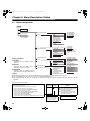
Panasonic Broadcast AJ-SPX800 Menu Information #,52:2 'PINKUJDQQMࡍࠫ㧞㧜㧜㧡ᐕ㧟㧝ᣣޓἫᦐᣣޓඦᓟ㧢ᤨ㧠㧥ಽ Chapter 8 Menu Description Tables 8-1 Menu Configuration MENU USER MENU MAIN MENU SYSTEM SETTING ROP MATRIX COLOR CORRECTION LOW SETTING MID SETTING HIGH SETTING ADDITIONAL DTL SKIN TONE DTL KNEE/LEVEL GAMMA FLARE CAMERA SETTING PAINT OPTION MENU OPTION VF CAM OPERATION Opening the Menus MAIN OPERATION USER MENU: Displayed when the MENU button is pressed. FILE MAIN MENU: Displayed when the MENU button is pressed for at least 3 seconds. CAMERA ID SHUTTER SPEED SHUTTER SELECT USER SW SW MODE WHITE BALANCE MODE USER SW GAIN IRIS SD CARD READ/WRITE SD CARD R/W SELECT LENS FILE SCENE INITIALIZE MAINTENANCE USER MENU SELECT OPTION MENU: Displayed when the MENU button is pressed while pressing the LIGHT button. <Notes> SYSTEM SETTING(USER) PAINT(USER) VF(USER) CAM OPE(USER) MAIN OPE(USER) FILE(USER) MAINTENANCE(USER) SYSTEM MODE OPTION MODE 1 OPTION MODE 2 REC FUNCTION OUTPUT SEL LCD MONITOR GENLOCK VF DISPLAY VF MARKER USER BOX VF INDICATOR1 VF INDICATOR2 MODE CHECK IND ! LED BATTERY/P2CARD BATTERY SETTING1 BATTERY SETTING2 MIC/AUDIO 1 MIC/AUDIO 2 TC/UB UMID SET/INFO SYSTEM CHECK LENS ADJ BLACK SHADING WHITE SHADING DIAGNOSTIC1 DIAGNOSTIC2 HOURS METER z The following items can be set: 42 camera-related items (14 C 3 pages), 14 recording-related items (1 page). z The items highlighted in grey cannot be selected by <USER MENU SELECT>. z The underlined items can only be selected as one whole page (with all sub-items). Individual sub-items cannot be selected separately. About Menu Description Tables The following letters indicate whether the modified menu data is saved to or read out from the memory. The – indicates that the data cannot be saved or read. S = Can be saved and read as scene data file. C = Can be saved or read using CARD READ/WRITESD. U = Can be saved and read as user data. Please refer to [8-7-4 SCENE] and [8-7-5 INITIALIZE]. F = Can be read using READ FACTORY DATA. Please refer to [8-7-5 INITIALIZE]. E = Can be saved using ECU DATA SAVE. Please refer to [5-9 Connecting the AJ-EC3P Extension Controller]. Items/ Adjustable Data Saved Range REC SIGNAL CAM VIDEO 1394 – C U F E This section shows the adjustable range of the set value, and available options for this item. 98 Remarks Select video input signals. CAM Record the signal from the camera VIDEO: Record the signal from the GENLOCK IN terminal 1394: Record the signal from the 1394 input terminal. (when optional AJYAD800G is attached.) About the settings available for this item. #,52:2 'PINKUJDQQMࡍࠫ㧞㧜㧜㧡ᐕ㧟㧝ᣣޓἫᦐᣣޓඦᓟ㧢ᤨ㧠㧥ಽ 8-2 SYSTEM SETTING 8-2-1 SYSTEM MODE Items/ Adjustable Data Saved Range REC SIGNAL CAM VIDEO 1394 – C U F E CAMERA MODE 60i 30P 24P 24PA S C U F E V.RES (24/30P) INTRLCE PROG. S C U F E ASPECT – C U F E Switch the operating mode of the camera. 60i: Camera operates in 60i mode. 30P: Camera operates in 30P mode. 24P: Camera operates in 24P mode (2:3) 24PA: Camera operates in 24PA mode (2:3:3:2) Set the vertical resolution when the 24P, 24PA, 30P mode is selected. INTRLCE: Lines are mixed. Natural images can be obtained. PROG. : Lines are not mixed. Complete progressive images can be obtained when images are edited after shooting. <Note> When PROG. is selected, images are recorded as progressive segmented frame images, which enables complete progressive editing. However, adding Vertical Detail (V.DTL) produces unnatural images. Therefore, we recommend using the camera with V.DTL set to 0. (Sufficient vertical response is maintained in the images after the progressive editing even when V.DTL is set to 0.) Select the aspect ratio for recording. 16:9: Record in <16:9> aspect ratio. 4:3: Record in <4:3> aspect ratio. 50M 25M DV Select the recording mode. 50M: Record in DVCPRO50 format. 25M: Record in DVCPRO format. DV: Record in DV format. 0% 7.5%A Switch the setup. (When the DVCPRO50 or DVCPRO format is selected.) 0%: Setup is switched to 0% for both the camera output and the recording. 7.5%A: Setup is switched to 7.5% for the camera output and 0% for the recording. – C U F E SET UP Select video input signals. CAM Record the signal from the camera VIDEO: Record the signal from the GENLOCK IN terminal 1394: Record the signal from the 1394 input terminal (when optional AJYAD800G is attached) <Notes> z After the power has been turned OFF, this setting defaults to CAM when the power is turned ON again. z With VIDEO selected, to synchronise this camera-recorder to the video signal (VBS) that is input to the GENLOCK IN terminal, the GENLOCK item in [8-2-7 GENLOCK] must be set to EXT. 16:9 4:3 – C U F E REC MODE Remarks Items/ Adjustable Data Saved Range REC TALLY RED GREEN CHAR Selects display of the recording status of the camera when the AJ-SPX800P is used with a 26-pin extender or Triax, or when it is controlling an external VTR, by setting the menu option 26PIN CONTROL to “BOTH”. The menu option 26PIN CONTROL is found in the OPTION MODE 2 screen on the SYSTEM setting page. RED: The red tally lamp lights up. GREEN:The green tally lamp lights up. CHAR: The VF displays [REC] in characters. ON OFF Select whether or not to enable illumination of the P2 card access LEDs. ON: Enable the P2 card access LEDs to light up for card status indications. OFF: LEDs remain off. ON OFF Select the USB drive mode when using the P2 card as bulk storage by connecting the AJ-SPX800P with a PC via USB2.0. ON: Switches to the USB drive mode. Recording, playback or thumbnail operation via the AJ-SPX800P is not permitted. OFF: Stops the USB drive mode, and returns to normal operation. <Note> After the power is turned off, this setting defaults to “OFF” when the power is next turned on. – C U F E ACCESS LED – C U F E USB – – U F – Remarks The ____ in the Adjustable Range column indicates the preset mode. 99 8 #,52:2 'PINKUJDQQMࡍࠫ㧞㧜㧜㧡ᐕ㧟㧝ᣣޓἫᦐᣣޓඦᓟ㧢ᤨ㧠㧥ಽ 8-2-2 OPTION MODE 1 Items/ Adjustable Data Saved Range P.OFF GPS DATA HOLD CLEAR – C U F – SDI METADATA ON OFF – C U F – SDI EDH ON OFF – C U F – SAVE SW (AUD ON OUT) OFF – C U F – SAVE SW (LCD) ON OFF – C U F – SAVE SW (SDI) ON OFF – C U F – 8-2-3 OPTION MODE 2 Remarks Select whether or not to hold the UMID GPS position information while the power is turned off, thereby keeping this information as status data holding the previous value until the power is turned on again, which enables a new measurement to start. HOLD: Hold and save the data. CLEARClear the data when the power is turned off, and save zero (No-Info) from the next power-on until a new measurement is completed. Select whether or not to output metadata (UMID) to the SDI (when the optional AJYA902AG is attached). COMPONENT OUT Sets the analog component output level to Triax, 26-pin extender, or external VTR. OFF: Saves power and stops output. However, when either a 26-pin extender, external VTR or Triax is connected, output automatically switches to BETACAM level. BETACAM: Output using ß-CAM level. M2: Output using M2 level. OFF BOTH Sets the recording control between the external VTR and the AJ-SPX800P when a 26-pin camera adapter (AJ-CA905G, optional) is attached and used with an external VTR. OFF: Recording is performed only with the AJ-SPX800P, and not with the external VTR. BOTH:Recording is performed with both the AJ-SPX800P, and an external VTR. <Note> The Tally Lamp indicates external VTR status. Recording status of the AJ-SPX800P can be selected in the menu option REC TALLY of SYSTEM MODE. NORMAL SPECIAL Sets the type of VTR control signal (start/ stop recording) which is output from No. 12 of the 26-pin connector when the 26-pin camera adapter (AJ-CA905G, optional) is attached and controls an external VTR. NORMAL: Recording stop "LOW", recording start “HIGH” (for AJ-D92). SPECIAL: Recording stop “HIGH”, recording start “LOW”. – C U F – 26PIN CONTROL Select whether or not to forcibly disable the audio output when the SAVE ON/OFF switch is set to [ON]. ON: Disable audio output. OFF: Enable audio output. Select whether or not to automatically turn off the LCD monitor when the SAVE ON/ OFF switch is set to [ON]. ON: Turn off LCD monitor. OFF: Do not turn off LCD monitor. – C U F – 26PIN CONTROL DEFAULT Select whether or not to automatically disable the SDI output when the SAVE ON/ OFF switch is set to [ON]. ON: Disable SDI output. OFF: Enable SDI output. Menu options for setting 1394 are displayed when an IEEE1394 interface board (AJ-YAD800G, optional) is attached. For more information, see the AJ-YAD800G instruction manual. – C U F – Remarks OFF BETACAM M2 Select whether or not to add an error detection flag to the SDI output (when the optional AJ-YA902AG is attached). <Note> 100 Items/ Adjustable Data Saved Range The ____ in the Adjustable Range column indicates the preset mode. #,52:2 'PINKUJDQQMࡍࠫ㧞㧜㧜㧡ᐕ㧟㧝ᣣޓἫᦐᣣޓඦᓟ㧢ᤨ㧠㧥ಽ 8-2-4 REC FUNCTION Items/ Adjustable Data Saved Range INTERVAL REC ON MODE ONE SHOT OFF – – – F – REC TIME 00s01f : 59s29f – C U F – PAUSE TIME – C U F – 00h00m00s01f : 00h04m59s29f : 23h59m59s29f TAKE TOTAL TIME NONE : – C U F – 5day TOTAL REC TIME 00m00s01f : 99m59s29f OVER100min NONE – – – – – AUDIO REC ON OFF Remarks Sets INTERVAL REC function. ON: Uses internal memory to perform interval recording. ONE SHOT: Performs “one-shot” recording for the duration specified under REC TIME, and then stops. OFF: INTERVAL REC is not performed. <Note> After the power is turned off, this setting defaults to OFF when the power is next turned on. Set REC TIME (1 cut). <Note> During 24P or 24PA modes, operations are performed in 5-frame units, and the fraction is truncated. The minimum operation is 5 frames (if the setting is 9 frames or fewer). Specify PAUSE time for recording. <Note> During 24P or 24PA modes, operations are performed in 5-frame units, and the fraction is truncated. The minimum operation is 5 frames. Specify the time needed for shooting. Select from NONE (continue until operation is manually stopped) to 5 days. Display total recorded time. The setting cannot be changed using this option. Displays the recording time (recording time needed for the P2 card) calculated using REC TIME, PAUSE TIME, and TAKE TOTAL TIME. <Note> During 24P mode or 24PA mode, operations are performed in 5-frame units, and the fraction is truncated. The displayed value is based on actual operation using 5 frames as a unit. Select whether or not sound will be recorded. – C U F – START DELAY 0SEC : – C U F – 10SEC Set the delay after pressing REC START to start recording in INTERVAL REC. PRE REC TIME 0SEC Set PRE RECORDING. 0-15SEC: Set the length of time that can be retrospectively recorded before the REC START button is pressed. <Note> The maximum selectable range is 8 seconds when the REC MODE in the <SYSTEM MODE> screen is set to 50M (DVCPRO50). : 15SEC – C U F – LOOP REC MODE – – – F – ON OFF Items/ Adjustable Data Saved Range VOICE MEMO RESERV ON OFF Set the available memory space for voice memos in P2 cards. ON: Reserve a voice memo area of 10 minutes or longer separately from the video recording capacity. The voice memo area can be used even when FULL is displayed for the recording capacity of the P2 card. OFF: Do not reserve any voice memo space. <Note> Even when this item is set to OFF, and FULL is displayed for the P2 card’s recording capacity, it may be possible to record voice memos depending on the status of the P2 card. ALL NORMAL Select operating modes that allow recording to start. ALL: Allow recording to start during stop, recording pause, and playback. NORMAL: Allow recording to start during stop and recording pause. <Note> When the INTERVAL REC MODE is set to either “ON” or “ONE SHOT”, the “ALL” setting for this option switches to “NORMAL” operation. Select the recording order of the slot when the power is turned on. HOLD: The recording order starts with the card previously selected when the power was turned off. SLOT1: The recording order starts with the card that is inserted in Slot 1 when the power is turned on. – C U F – REC START – C U F – P.ON REC SLOT SEL Remarks HOLD SLOT1 – C U F – <Note> Displayed REC TIME, PAUSE TIME and TOTAL REC TIME are translated into either drop-frame or non-drop-frame according to the mode of operation. TAKE TOTAL TIME is actual time. Therefore, TOTAL REC TIME may incorporate fractions, depending on the settings. Example of drop-frame Select whether or not to enable LOOP REC. This setting can be used with PRE RECORDING features. ON: Enable LOOP REC. OFF: Disable LOOP REC. <Note> After the power is turned off, this item will default to OFF the next time the power is turned on. REC TIME 02s00f PAUSE TIME 02s00f TAKE TOTAL TIME 40min TOTAL REC TIME 19m59s06f The ____ in the Adjustable Range column indicates the preset mode. 101 8 #,52:2 'PINKUJDQQMࡍࠫ㧞㧜㧜㧡ᐕ㧟㧝ᣣޓἫᦐᣣޓඦᓟ㧢ᤨ㧠㧥ಽ 8-2-5 OUTPUT SEL Items/ Adjustable Data Saved Range VIDEO OUT SEL VBS VF Y SDI 8-2-6 LCD MONITOR Remarks Select the output signal on the VIDEO OUT terminal. VBS: Output a regular composite signal. VF: Output a VF Y signal. The status display is also superimposed. Y: Output a component Y signal. SDI: Output an SDI signal. Only selectable when the optional AJ-YA902AG extension board is attached. – C U F – MONITOR OUT ON CHAR OFF – C U F – – C U F – 102 Select whether or not to superimpose characters on the MON OUT terminal signal independently of the camera’s VIDEO OUT CHARACTER switch. (The character content is the same as the video output signal.) ON: Enable superimpose. OFF: Disable superimpose. Select whether or not to superimpose characters on the LCD monitor. (The character content is the same as the video output signal.) ON: Enable superimpose. (Not interlocked with the VIDEO OUT CHARACTER switch.) OFF: Disable superimpose. (Not interlocked with the VIDEO OUT CHARACTER switch.) EE/PB EE Select the image to display in the viewfinder. EE/PB: Display the playback image in the playback mode. EE: Always display the camera image. ON OFF Select whether or not to output clip thumbnails displayed on the LCD monitor to the video output and monitor output signals. ON: Enable output. OFF: Disable output. – C U F – THUMBNAIL OUT Set the character contents superimposed onto the output signals for the VIDEO OUT terminal (Analog or SDI) and MON OUT terminal. TC: Display the time code. (Displays the menu when menu characters are superimposed.) <Note> The TC display position moves up and down depending on the camera ID position. STATUS: Display the same characters superimposed on the VF signal. (Displays the menu when menu characters are superimposed.) MENU ONLY: Displays only when the menu characters are superimposed. No display appears when other characters are superimposed. ON OFF – C U F – VF MODE BRIGHTNESS –7 Remarks Adjust the LCD monitor brightness. : +0 : – C U F – +7 COLOR LEVEL –7 Adjust the LCD monitor chroma level. : +0 : – C U F – +7 CONTRAST – C U F – OUTPUT CHAR TC STATUS MENU ONLY LCD MON CHAR Items/ Adjustable Data Saved Range –7 Adjust the LCD monitor contrast. : +0 : – C U F – +7 BACKLIGHT HIGH NORMAL Select whether or not to set the LCD monitor brightness to always high. HIGH: Set to always high. NORMAL: The brightness changes according to the BRIGHTNESS setting. NORMAL MIRROR Select whether or not to change the LCD monitor to mirror image. NORMAL: Do not change to mirror image. MIRROR: Change to mirror image. – C U F – SELF SHOOT – C U F – ASPECT CONV. LT.BOX SQUEEZE – C U F – Select a screen ratio for images displayed on the LCD monitor. LT.BOX: Display images in the letter box size. SQEEZE: Display images in the squeeze size. <Note> This item is enabled only when ASPECT described in “8-2-1 SYSTEM MODE” is set to16:9. The ____ in the Adjustable Range column indicates the preset mode. #,52:2 'PINKUJDQQMࡍࠫ㧞㧜㧜㧡ᐕ㧟㧝ᣣޓἫᦐᣣޓඦᓟ㧢ᤨ㧠㧥ಽ 8-3 PAINT 8-2-7 GENLOCK Items/ Adjustable Data Saved Range GENLOCK INT EXT 26P EXT – C U F E H PHASE COARSE –50 : +00 8-3-1 ROP Remarks Switch the camera synchronising signal. INT: Synchronise with the internal reference signal regardless of the reference signal input to the GENLOCK IN terminal. EXT: Synchronise with the reference signal input to the GENLOCK IN terminal. 26P EXT: Synchronizes to the signal input via the 26-pin connector. Perform coarse phase adjustment for horizontal hold when configuring a system. : +000 : +160 – – – – – SC PHASE COARSE SC PHASE FINE Set the master pedestal level. : +000 : S C U F E +200 MASTER DTL –31 Set the H Detail and V Detail levels. : +00 : S C U F E +31 MASTER 0.35 : GAMMA 0.45 Set MASTER GAMMA in 0.01 steps. Perform fine phase adjustment for horizontal hold when configuring a system. <Note> This adjustment simultaneously shifts the SC phase. KNEE POINT 70.0% Set the KNEE POINT position in 0.5% steps. : 85 0% : S C U F E 107.0% KNEE SLOPE 0 Set the KNEE slope. : 0 1 Perform coarse SC PHASE adjustment when GENLOCK is set. 3 50 : S C U F E 99 R GAIN –200 8 Set the Rch gain. : –75 : +00 : +75 – – – – – –200 : : – – – – – MASTER PED Remarks S C U F E 0.75 : – – – – – +50 H PHASE FINE –160 Items/ Adjustable Data Saved Range Perform fine SC PHASE adjustment when GENLOCK is set. <Note> When adjusting GENLOCK, please adjust H PHASE first, and then adjust SC PHASE. +000 : S C U F E +200 G GAIN –200 Set the Gch gain. : +000 : S C U F E +200 B GAIN –200 Set the Bch gain. : +000 : S C U F E +200 R PEDESTAL –100 Set the Rch pedestal level. : +000 : S C U F E +100 G PEDESTAL –100 Set the Gch pedestal level. : +000 : S C U F E +100 B PEDESTAL –100 Set the Bch pedestal level. : +000 : S C U F E +100 The ____ in the Adjustable Range column indicates the preset mode. 103 #,52:2 'PINKUJDQQMࡍࠫ㧞㧜㧜㧡ᐕ㧟㧝ᣣޓἫᦐᣣޓඦᓟ㧢ᤨ㧠㧥ಽ 8-3-2 MATRIX 8-3-3 COLOR CORRECTION Items/ Adjustable Data Saved Range MATRIX TABLE Remarks Items/ Adjustable Data Saved Range A B Select the color correction table. 2 types of tables can be stored: type A and type B. R (SAT/PHASE) –31 Adjust the tint. S C U F E +63 S C U F E MATRIX R-G : +00 Perform red color correction (saturation and hue). : R-Mg (SAT/PHASE) : +06 : S C U F E +31 MATRIX R-B –31 : : : : : : +00 Perform color correction (saturation and hue) between magenta and blue. –63 : +00 Perform blue color correction (saturation and hue). S C U F E +63 B-Cy –63 (SAT/PHASE) : +00 Perform color correction (saturation and hue) between blue and cyan. : Adjust the tint. : S C U F E +63 Cy (SAT/PHASE) –05 : S C U F E +31 OFF A S C U F E B –63 : Adjust the tint. +07 S C U F E +31 –31 +00 Perform magenta color correction (saturation and hue). S C U F E +63 B (SAT/PHASE) : MATRIX B-G : : Adjust the tint. –01 S C U F E +31 MATRIX B-R –31 –63 S C U F E +63 Mg-B (SAT/PHASE) : S C U F E +31 –31 +00 Perform color correction (saturation and hue) between red and magenta. : Adjust the tint. +06 MATRIX G-B : S C U F E +63 Mg (SAT/PHASE) : S C U F E +31 MATRIX G-R –31 –63 : Adjust the tint. +12 MATRIX TABLE –63 Remarks –63 : +00 Perform cyan color correction (saturation and hue). : Select the color correction table to be applied to the selected GAIN switch (L/M/H). S C U F E +63 Cy-G (SAT/PHASE) –63 : +00 Perform color correction (saturation and hue) between cyan and green. : <Note> S C U F E +63 The items indicated by are the setting items for PAINT MENU SW() R/W in the <SD CARD R/W SELECT> screen. The items without are the setting items for PAINT MENU LEVEL R/W. Please refer to [8-7-2 SD CARD R/W SELECT] for more information. G (SAT/PHASE) –63 : +00 Perform green color correction (saturation, hue). : S C U F E +63 G-Yl (SAT/PHASE) –63 : +00 Perform color correction (saturation, hue) between green and yellow. : S C U F E +63 Yl (SAT/PHASE) –63 : +00 Perform yellow color correction (saturation, hue). : S C U F E +63 Yl-R (SAT/PHASE) –63 : +00 Perform color correction (saturation, hue) between yellow and red. : S C U F E +63 COLOR CORRECT S C U F E ON OFF Select whether or not to enable color correction for the selected GAIN switch (L/M/H). ON: Enable correction. OFF: Disable correction. The ____ in the Adjustable Range column indicates the preset mode. 104 #,52:2 'PINKUJDQQMࡍࠫ㧞㧜㧜㧡ᐕ㧟㧝ᣣޓἫᦐᣣޓඦᓟ㧢ᤨ㧠㧥ಽ 8-3-4 LOW SETTING Items/ Adjustable Data Saved Range MASTER GAIN –3dB : 0dB 8-3-5 MID SETTING Remarks Select the master gain from –3, 0, 3, 6, 9, 12, 15, 18, 21, 24, 27, or 30dB. Items/ Adjustable Data Saved Range MASTER GAIN : 00 Set H.DTL LEVEL. H.DTL LEVEL : 17 14 00 : Set V.DTL LEVEL. V.DTL LEVEL : 24 20 S C U F E 31 Set DTL CORING. DTL CORING : 03 : : 20 : S C U F E 31 LEVEL 0 DEPEND. 1 : 5 S C U F E 0.35 S C U F E 15 Set a frequency (DTL width) at which H.DTL is added. The greater the value, the higher the frequency (the narrower the DTL). Set LEVEL DEPEND. No DTL is added to the portion whose brightness is the setting value or less. When the GAMMA MODE SEL item is set to STD, each setting value represents brightness levels, as follows: 0 = about 0%, 1 = about 4%, 2 = about 8%, 3 = about 12%, 4 = about 16%, 5 = about 20%. Set MASTER GAMMA in 0.01 steps. : 0.45 H.DTL FREQ. 20 : S C U F E 31 LEVEL 0 DEPEND. 1 : 5 S C U F E MASTER GAMMA 0.35 Set a frequency (DTL width) at which H.DTL is added. The greater the value, the higher the frequency (the narrower the DTL). Set LEVEL DEPEND. No DTL is added to the portion whose brightness is the setting value or less. When the GAMMA MODE SEL item is set to STD, each setting value represents brightness levels, as follows: 0 = about 0%, 1 = about 4%, 2 = about 8%, 3 = about 12%, 4 = about 16%, 5 = about 20%. Set MASTER GAMMA in 0.01 steps. : 0.45 : S C U F E 0.75 S C U F E 0.75 Set the gamma curb for dark spots. : OFF BLACK STRETCH : –3 Set the gamma curb for dark spots. : OFF : S C U F E +3 MATRIX TABLE 00 : : –3 Set DTL CORING. : S C U F E 15 BLACK STRETCH 00 : 02 00 Set V.DTL LEVEL. : S C U F E 31 MASTER GAMMA 00 : 00 Set H.DTL LEVEL. S C U F E 63 : H.DTL FREQ. 00 : S C U F E 63 DTL CORING 9dB Select the master gain from –3, 0, 3, 6, 9, 12, 15, 18, 21, 24, 27, or 30dB. S C U F E 30dB : V.DTL LEVEL : : S C U F E 30dB H.DTL LEVEL –3dB Remarks S C U F E +3 OFF A S C U F E B Select the color correction table. MATRIX TABLE OFF A S C U F E B Select the color correction table. COLOR CORRECT Set the color correction to ON or OFF. COLOR CORRECT Set the color correction to ON or OFF. ON OFF S C U F E <Note> The items indicated by are the setting items for PAINT MENU SW() R/W in the <SD CARD R/W SELECT> screen. The items without are the setting items for PAINT MENU LEVEL R/W. Please refer to [8-7-2 SD CARD R/W SELECT] for more information. ON OFF S C U F E The ____ in the Adjustable Range column indicates the preset mode. 105 8 #,52:2 'PINKUJDQQMࡍࠫ㧞㧜㧜㧡ᐕ㧟㧝ᣣޓἫᦐᣣޓඦᓟ㧢ᤨ㧠㧥ಽ 8-3-6 HIGH SETTING Items/ Adjustable Data Saved Range MASTER GAIN –3dB : 18dB 8-3-7 ADDITIONAL DTL Remarks Select the master gain from –3, 0, 3, 6, 9, 12, 15, 18, 21, 24, 27, or 30dB. : 00 KNEE APE LVL OFF 1 2 Set H.DTL. : 12 S C U F E 5 CHROMA DTL OFF 1 00 S C U F E Set V.DTL LEVEL. DTL GAIN(+) : Set DTL CORING. S C U F E +31 DTL GAIN(–) –31 : : 08 +00 : : 20 : S C U F E 31 0 LEVEL DEPEND. : 3 : 5 S C U F E MASTER GAMMA Set a frequency (DTL width) at which H.DTL is added. The greater the value, the higher the frequency (the narrower the DTL). Set LEVEL DEPEND. No DTL is added to the portion whose brightness is the setting value or less. When the GAMMA MODE SEL item is set to STD, each setting value represents brightness levels, as follows: 0 = about 0%, 1 = about 4%, 2 = about 8%, 3 = about 12%, 4 = about 16%, 5 = about 20%. Set MASTER GAMMA in 0.01 steps. : S C U F E 63 Adjust the detail signal clip towards the + direction. DTL SOURCE (R+G)/2 (G+B)/2 2G+R+B /4 (3G+R)/4 R S C U F E G Set the signal source for detail signal components. H.DTL LINE MIX 1H 2H Set the scan line to generate the H.DTL signal. 0.55 CORNER DTL ON OFF : S C U F E : –3 Set the gamma curb for dark spots. : OFF : S C U F E +3 MATRIX TABLE OFF A S C U F E B Select the color correction table. COLOR CORRECT Set the color correction to ON or OFF. ON OFF S C U F E <Note> The items indicated by are the setting items for PAINT MENU SW() R/W in the <SD CARD R/W SELECT> screen. The items without are the setting items for PAINT MENU LEVEL R/W. Please refer to [8-7-2 SD CARD R/W SELECT] for more information. 106 S C U F E +31 DTL CLIP 00 S C U F E 0.35 S C U F E 0.75 BLACK STRETCH Adjust the detail level toward the – (downwards). : S C U F E 15 00 Adjust the detail level toward + (upwards). : S C U F E 31 H.DTL FREQ. –31 +00 : 00 5 : 17 DTL CORING Set KNEE APE LEVEL. Set the chroma detail. Detects the chroma edge and superimposes it on Y to enhance H.DTL. A greater value increases the correction. : : S C U F E 63 V.DTL LEVEL Remarks : S C U F E 30dB H.DTL LEVEL Items/ Adjustable Data Saved Range ON/OFF switching for CORNER DTL mode, which enhances the resolution around the screen perimeter. The ____ in the Adjustable Range column indicates the preset mode. #,52:2 'PINKUJDQQMࡍࠫ㧞㧜㧜㧡ᐕ㧟㧝ᣣޓἫᦐᣣޓඦᓟ㧢ᤨ㧠㧥ಽ 8-3-8 SKIN TONE DTL Items/ Adjustable Data Saved Range SKIN TONE DTL 8-3-9 KNEE/LEVEL Items/ Adjustable Data Saved Range Remarks ON OFF Set the skin tone DTL to ON or OFF. MASTER PED ON OFF ON/OFF switching for ZEBRA within the SKIN TONE range. 0 Adjust the effect of SKIN TONE DTL CORING. +000 : S C U F E +200 MANUAL KNEE S C U F E SKIN DTL CORING : 5 Set the KNEE POINT position in 0.5% steps. : Used when obtaining the target hue for SKIN TONE DTL. Align the center marker and the target object with each other. – – – – – 000 Set the maximum value of the brightness signal to which SKIN TONE effect is enabled. : 190 : S C U F E 255 Y MIN 000 Set the minimum value of the brightness signal to which the SKIN TONE effect is enabled. : 010 : S C U F E 255 I CENTER 000 Set the center position on the I axis (the area where SKIN TONE is enabled). : 022 S C U F E 107.0% KNEE SLOPE 00 : 50 : 99 (98) S C U F E WHITE CLIP ON OFF S C U F E WHITE CLIP LVL 90% 105% : 85% Set the area width where SKIN TONE is enabled along the I axis above and below the I CENTER. 010 : 8 Set WHITE CLIP LEVEL. : A.KNEE POINT 80% : Set the WHITE CLIP feature to ON or OFF. The WHITE CLIP LVL set value is enabled when this setting is ON. : : 000 Set the KNEE SLOPE. 0 setting is equal to KNEE OFF. <Note> The adjustable range when using the AJEC3P is from 00 to 98. S C U F E 109% S C U F E 255 : S C U F E 107% A.KNEE LVL 100 Set the AUTO KNEE POINT position in 0.5% steps. This setting is enabled when the OUTPUT/AUTO KNEE selector switch is set to CAM.AUTO KNEE ON. Set the AUTO KNEE LEVEL. : S C U F E 255 105 000 Set the area width where SKIN TONE is enabled along the Q axis above and below the I CENTER. : 005 : S C U F E 255 Q PHASE 70.0% 85.0% SKIN TONE GET Q WIDTH Set the mode when the AUTO KNEE switch is OFF. The KNEE POINT/SLOPE set value is enabled when this setting is ON. : : I WIDTH ON OFF S C U F E KNEE POINT S C U F E 7 Y MAX Set the master pedestal. : S C U F E SKIN TONE ZEBRA –200 Remarks –128 Set the phase in the area where SKIN TONE is enabled based on the Q axis. : +000 : S C U F E 109 A.KNEE RESPONSE S C U F E 1 : 4 Set the AUTO KNEE response speed. The smaller the setting value, the faster the response speed. <Note> : S C U F E +127 Y R-Y The items indicated by are the setting items for PAINT MENU SW() R/W in the <SD CARD R/W SELECT> screen. The items without are the setting items for PAINT MENU LEVEL R/W. Please refer to [8-7-2 SD CARD R/W SELECT] for more information. Q-WIDTH I-WIDTH Y-MAX + direction The ____ in the Adjustable Range column indicates the preset mode. I-CENTER – direction Q-PHASE B-Y = SKIN TONE AREA Y-MIN 0 107 #,52:2 'PINKUJDQQMࡍࠫ㧞㧜㧜㧡ᐕ㧟㧝ᣣޓἫᦐᣣޓඦᓟ㧢ᤨ㧠㧥ಽ 8-3-10 GAMMA Items/ Adjustable Data Saved Range MASTER GAMMA 0.35 8-3-11 FLARE Remarks Set the master gamma in 0.01% steps. 0.45 –15 S C U F E G FLARE Set the Rch gamma. : Set the R FLARE. B FLARE : S C U F E +15 100 000 Set the G FLARE. : S C U F E +00 –15 000 Remarks : S C U F E 0.75 B GAMMA R FLARE : : R GAMMA Items/ Adjustable Data Saved Range 100 000 Set the B FLARE. : Set the Bch gamma. : S C U F E 100 +00 : S C U F E +15 GAMMA MODE STD SEL NEWS FILM LIKE1 FILM LIKE2 S C U F E 108 Select the gamma. STD: Standard gamma feature. NEWS: This video gamma feature can effectively reproduce gradations by reducing whiteouts and blackouts when shooting an object with partially highlighted areas. This gamma is especially effective in the AUTO KNEE mode. FILM LIKE1: Cinema gamma feature for video. This gamma is set with scene file 4 as the factory setting. FILM LIKE2: Cinema gamma feature for video. This gamma feature can reproduce gradations in highlighted areas better than FILM LIKE1 gamma. <Notes> z Selecting NEWS gamma disables settings under the items KNEE SLOPE, KNEE POINT, and A.KNEE POINT outlined in [8-3-9 KNEE/LEVEL]. These settings are also disabled when NEWS gamma is selected with the USER switch. z When FILELIKE1 or FILELIKE2 is selected, little change occurs and a certain curve is maintained when the setting value for the KNEE SLOPE item in [8-3-9 KNEE/LEVEL] is 00 to 50. The ____ in the Adjustable Range column indicates the preset mode. #,52:2 'PINKUJDQQMࡍࠫ㧞㧜㧜㧡ᐕ㧟㧝ᣣޓἫᦐᣣޓඦᓟ㧢ᤨ㧠㧥ಽ 8-4 VF 8-3-12 CAMERA SETTING Items/ Adjustable Data Saved Range DETAIL 8-4-1 VF DISPLAY Items/ Adjustable Data Saved Range Remarks ON OFF Set the DTL (H, V) to ON or OFF. DISP CONDITION ON OFF ON/OFF switching for the two-dimensional LPF that reduces cross-color. DISP MODE ON OFF ON/OFF switching for the HIGH COLOR mode, which enhances the color dynamic range. S C U F E 2D LPF S C U F E GAMMA ON OFF Set the gamma circuit to ON or OFF. ON OFF Switch the test signal ON or OFF. VF DTL ON OFF Set the DISP MODE. Switch the camera’s Warning/Message indication. Please refer to [4-7-4 Display Modes and Setting Changes/adjustment Result Messages] for more information. Y NAM R G B Select the VF output. Y: Brightness signal NAM: Output signal with the highest level among R, G, and B signals. R: Rch signal G: Gch signal B: Bch signal 0 Select the VF DTL. Additionally enhance the DTL for the VF signal. 0 setting is the same DTL as the primary scan lines. ON OFF S C U F E : Set the flare correction to ON or OFF. 3 : S C U F E H-F COMPE. 1 2 3 – C U F E S C U F E FLARE NORMAL: Display status constantly. HOLD: Display status only when the MODE CHECK switch is pressed. – C U F E VF OUT S C U F E TEST SAW NORMAL HOLD – C U F E S C U F E HIGH COLOR ON/OFF switching for the H-F COMPE mode, which enhances the DTL in the highfrequency range. Remarks – C U F E 5 ZEBRA1 0% : DETECT 70% Set the ZEBRA1 detection level (IRE value). : – C U F E 109% ZEBRA2 DETECT ZEBRA Pattern Display 0% Set the ZEBRA2 detection level (IRE value). : 85% : – C U F E 109% Video Level 109% ON ZEBRA 2 OFF SPOT ZEBRA 2 DETECT ZEBRA2 ON SPOT – C U F E OFF Set the ZEBRA2 to ON, OFF, or SPOT. LOW LIGHT LVL OFF 10% 15% 20% 25% 30% – C U F E 35% Set the camera incoming light volume at which to display LOW LIGNT. ECU MENU DISP. ON OFF Set the menu display on the VF to ON or OFF when the ECU is connected. ON OFF Set the 50M recording indication to ON or OFF. – C U F E ZEBRA 1 DETECT 50M INDICATOR – C U F E 0% <Note> All items in CAMERA SETTING are setting targets of the item PAINT MENU SW() R/W in the <SD CARD R/W SELECT> screen. MARKER/CHAR 50% LVL 60% 70% 80% 90% – C U F E 100% Adjust the brightness of markers and characters displayed on the VF. The ____ in the Adjustable Range column indicates the preset mode. 109 8 #,52:2 'PINKUJDQQMࡍࠫ㧞㧜㧜㧡ᐕ㧟㧝ᣣޓἫᦐᣣޓඦᓟ㧢ᤨ㧠㧥ಽ 8-4-2 VF MARKER Items/ Adjustable Data Saved Range TABLE A B – C U F E CENTER MARK OFF 1 2 3 4 – C U F E SAFETY ZONE OFF 1 2 – C U F E SAFETY AREA 80% 8-4-4 VF INDICATOR1 Remarks Items/ Adjustable Data Saved Range Select the VF MARKER setting table. First, select table A or B, then set the items below for each table. EXTENDER Switch the center mark. OFF: Do not display center mark. 1: + (large) 2: Hollow (large) 3: + (small) 4: Hollow (small) SHUTTER Select the frame type for the safety zone. OFF: Do not display frame. 1: Box 2: Corner frame Set the position of the safety zone. FRAME LVL Set the level outside the frame marker. 0: Equivalent to signal OFF. 15: Same brightness as center area. This setting, however, is disabled if the FRAME SIG is set to VISTA. 15 – C U F E USER BOX Remarks ON OFF Select whether or not to display the USER BOX. 1 Set the width of the USER BOX. 13 : : 13 : +00 Set to ON or OFF the indications for current gain setting, S.GAIN, and DS.GAIN. OFF IRIS S+IRIS S OFF: Disable indications of both the super iris ON status and the iris value. IRIS: Enable only the iris value indication. S+IRIS: Enables indications of the super iris ON status and the iris value. S: Enable indication of the super iris ON status. (The iris value indication and the iris override indication/non indication are interlocked.) Select when to enable the ID mix during recording. BAR: Enable when recording color bars. CAM: Enable when recording camera image. ALWAYS: Enable always. OFF: Disable ID mix. BAR CAM ALWAYS OFF UPPER R UPPER L LOWER R LOWER L Set the camera ID recording position. UPPER R: Upper right. UPPER L: Upper left. LOWER R: Lower right. LOWER L: Lower left. ON OFF Select whether or not to simultaneously mix the year/month/date and hour/minute/ second when recording the camera ID. ON OFF Set the zoom position indication to ON or OFF. – C U F E COLOR TEMP ON OFF Set the color temperature indication to ON or OFF. – C U F E : –50 ON OFF – C U F E Set the height of the USER BOX. – C U F E 121 USER BOX H POS Set the AWB PRE/A/B indication to ON or OFF. – C U F E DATE/TIME ZOOM LVL : 1 ON OFF – C U F E CAMERA ID ID POSITION – C U F E 100 USER BOX HEIGHT Set the filter No. indication to ON or OFF. – C U F E GAIN – C U F E USER BOX WIDTH ON OFF – C U F E 8-4-3 USER BOX Items/ Adjustable Data Saved Range Set the shutter speed indication to ON or OFF. – C U F E WHITE Set the frame marker. Only enabled when REC MODE is set to 16:9. The VISTA ratio is 16:8.65. Set the frame marker to ON or OFF. : ON OFF – C U F E FILTER IRIS FRAME MARK ON – C U F E OFF 0 Set the extender indication to ON or OFF. – C U F E : – C U F E 100% FRAME SIG 4:3 13:9 14:9 – C U F E VISTA ON OFF – C U F E : 90% Remarks Set the horizontal position of the USER BOX. CAMERA MODE ON OFF Set the camera operation mode indication to ON or OFF. – C U F E : – C U F E +50 USER BOX V POS –121 : +000 : – C U F E +121 110 Set the vertical position of the USER BOX. The ____ in the Adjustable Range column indicates the preset mode. #,52:2 'PINKUJDQQMࡍࠫ㧞㧜㧜㧡ᐕ㧟㧝ᣣޓἫᦐᣣޓඦᓟ㧢ᤨ㧠㧥ಽ 8-4-5 VF INDICATOR2 Items/ Adjustable Data Saved Range P2CARD REMAIN TOTAL ONE-CARD OFF Select the indication mode for the P2 card’s remaining capacity. TOTAL: Display the total remaining capacity of all P2 cards in slots. ONE-CARD: Display the remaining capacity of the P2 card currently used for recording. OFF: Disable the remaining capacity indication. ON OFF Set the battery voltage indication to ON or OFF. – C U F E BATTERY Remarks REC STATUS ON OFF Set the audio lever meter indication to ON or OFF. TCG TCR TCG/TCR OFF Select the time code to display. TCG: Display the time code generator value in E-E mode. TCR: Display the time code reader value in V-V mode. TCG/TCR: Display the time code generator value in E-E mode, and the time code reader value in V-V mode. OFF: Disable the time code display. ON OFF – C U F – PROXY REC – C U F E AUDIO LVL Items/ Adjustable Data Saved Range ON OFF – C U F E TC – C U F E SYSTEM INFO ALWAYS NORMAL OFF – C U F E SAVE LED P2CARD SAVE – C U F E DV ON OFF – C U F E VOICEMEMO – C U F E ON OFF Select the method of displaying system information and warnings. ALWAYS: Always display warnings. NORMAL: Display warnings for 3 seconds only when problems occur. OFF: Display no warnings other than “TURN POWER OFF” and “SYSTEM ERROR”. Set the SAVE lamp function. P2CARD: The lamp blinks in synch with the warning message when the P2 card’s remaining recording capacity is getting low. SAVE: The lamp lights up when the SAVE ON/OFF switch is set to ON and the output system assigned in [8-2-2 OPTION MODE 1] is in the save mode. DV Select whether or not to enable DV indication when the format is set to DV. ON: Enable DV indication. OFF: Disable DV indication. – C U F – Remarks Select whether or not to enable “REC” indication in the viewfinder and on the LCD monitor during recording. ON: REC indication enabled. OFF: REC indication not enabled. <Note> This option is useful when the AJ-SPX800P is used independently. When a 26-pin extender, external VTR, or Triax is connected, settings are subject to the setting of the menu option REC TALLY in SYSTEM MODE. When a video encoder card (AJ-YAX800G, optional) is attached, proxy recording information is displayed when recording starts. ON: Display indicating whether proxy recording is to be performed on the P2 card only, or on both the P2 card and the SD memory card. OFF: Proxy recording information is not displayed. 8 8-4-6 MODE CHECK IND Items/ Adjustable Data Saved Range STATUS Remarks ON OFF Select whether or not to display the status indication during MODE CHECK. ON OFF Select whether or not to display the cause indication screen when the ! LED turns on during MODE CHECK ON OFF Select whether or not to display the FUNCTION indication screen during MODE CHECK. ON OFF Select whether or not to display the AUDIO indication screen during MODE CHECK. ON OFF Select whether or not to display the status indication screen after the power is turned ON. – C U F E !LED – C U F E FUNCTION – C U F E AUDIO – C U F E P.ON IND – C U F E The ____ in the Adjustable Range column indicates the preset mode. Select whether or not to enable the V indication during voice memo recording. ON: Enable V indication. OFF: Disable V indication. 111 #,52:2 'PINKUJDQQMࡍࠫ㧞㧜㧜㧡ᐕ㧟㧝ᣣޓἫᦐᣣޓඦᓟ㧢ᤨ㧠㧥ಽ 8-5 CAM OPERATION 8-4-7 !LED Items/ Adjustable Data Saved Range GAIN(0dB) 8-5-1 CAMERA ID Remarks ON OFF Select whether or not to illuminate when GAIN is set to other than 0 dB. ID1 ON OFF Select whether or not to illuminate when GAIN is set to other than -3 dB. ID2 ON OFF Select whether or not to illuminate when DS.GAIN (storage gain) is ON. ID3 ON OFF Select whether or not to illuminate when the shutter is set to ON. ON OFF Select whether or not to illuminate when the WHITE BAL switch is set to PRST. ON OFF Select whether or not to illuminate when the lens is in EXTENDER mode. ON OFF Select whether or not to illuminate when BLACK STRETCH is used. – C U F E GAIN (-3dB) Setting 3 for the CAMERA ID recorded on color bars. Up to 10 characters are allowed for this setting. – C U F – – C U F E WHITE PRESET Setting 2 for the CAMERA ID recorded on color bars. Up to 10 characters are allowed for this setting. – C U F – – C U F E SHUTTER Remarks Setting 1 for the CAMERA ID recorded on color bars. Up to 10 characters are allowed for this setting. – C U F – – C U F E DS.GAIN Items/ Adjustable Data Saved Range <Note> This setting is canceled when READ FACTORY DATA is selected. – C U F E EXTENDER 8-5-2 SHUTTER SPEED – C U F E BLACK STR – C U F E MATRIX ON OFF Select whether or not to illuminate when MATRIX is set to ON. COLOR ON CORRECTION OFF Select whether or not to illuminate when COLOR CORRECTION is set to ON. ON OFF ON OFF Select whether or not to illuminate when SUPER V is set to ON. OFF W/O 50M W/O 25M W/O DV Select whether or not to illuminate according to the recording mode. OFF: Does not illuminate in any recording mode. W/O 50M: Illuminate except in DVCPRO50 mode. W/O 25M: llluminate except in DVCPRO mode. W/O DV: Illuminate except in DV mode. Select whether or not to illuminate when auto-tracking white balance is allocated to the WHITE BAL switch B. – C U F E ATW ON OFF – C U F E D.ZOOM ON OFF Select whether or not to illuminate during digital zoom operation. POSITION2 ON OFF Allocate SUPER V as a shutter speed selectable by the shutter switch. ON OFF Allocate the shutter speed set by POSITION1 SELECT in the <SHUTTER SELECT> screen as the shutter speed selectable by the shutter switch. ON OFF Allocate the shutter speed set by POSITION2 SELECT in the <SHUTTER SELECT> screen as the shutter speed selectable by the shutter switch. ON OFF Allocate the shutter speed set by POSITION3 SELECT in the <SHUTTER SELECT> screen as the shutter speed selectable by the shutter switch. ON OFF Allocate the shutter speed set by POSITION4 SELECT in the <SHUTTER SELECT> screen as the shutter speed selectable by the shutter switch. ON OFF Allocate the shutter speed set by POSITION5 SELECT in the <SHUTTER SELECT> screen as the shutter speed selectable by the shutter switch. ON OFF Allocate the shutter speed set by POSITION6 SELECT in the <SHUTTER SELECT> screen as the shutter speed selectable by the shutter switch. – C U F E POSITION3 – C U F E POSITION4 – C U F E POSITION5 – C U F E POSITION6 – C U F E <Note> If both GAIN (0 dB) and GAIN (–3 dB) are set to ON, the LED illuminates except when GAIN is adjusted to 0 dB and –3 dB. 112 Allocate SYNCHRO SCAN as a shutter speed selectable by the shutter switch. – C U F E – C U F E 50M/25M/DV ON OFF – C U F E Select whether or not to illuminate the lamp when filter1 (3200K) is not 3200K. – C U F E Remarks – C U F E POSITION1 – C U F E SUPER V SYNCHRO SCAN SUPER V – C U F E FILTER Items/ Adjustable Data Saved Range – C U F E The ____ in the Adjustable Range column indicates the preset mode. #,52:2 'PINKUJDQQMࡍࠫ㧞㧜㧜㧡ᐕ㧟㧝ᣣޓἫᦐᣣޓඦᓟ㧢ᤨ㧠㧥ಽ 8-5-3 SHUTTER SELECT Items/ Adjustable Data Saved Range SUPER V MODE 8-5-4 USER SW Remarks FRM1 FRM2 Select the SUPER V switching mode. FRM1: Normal mode. FRM2: After-image reduction mode. <Note> The SUPER V mode increases vertical resolution by directly outputting the photodiode vertical signal from the CCD. FRM1 sets the accumulation level to 1/30th second. FRM sets the level to 1/60th second, reducing sensitivity by half. POSITION1 SEL 1/100 1/120 1/250 1/500 1/1000 – C U F E 1/2000 Select the shutter speed to be allocated to POSITION1. POSITION2 SEL 1/100 1/120 1/250 1/500 1/1000 – C U F E 1/2000 Select the shutter speed to be allocated to POSITION2. POSITION3 SEL 1/100 1/120 1/250 1/500 1/1000 – C U F E 1/2000 Select the shutter speed to be allocated to POSITION3. POSITION4 SEL 1/100 1/120 1/250 1/500 1/1000 – C U F E 1/2000 Select the shutter speed to be allocated to POSITION4. POSITION5 SEL 1/100 1/120 1/250 1/500 1/1000 – C U F E 1/2000 Select the shutter speed to be allocated to POSITION5. POSITION6 SEL Select the shutter speed to be allocated to POSITION6. – C U F E 1/100 1/120 1/250 1/500 1/1000 – C U F E 1/2000 Items/ Adjustable Data Saved Range Remarks USER MAIN SW INH S.GAIN DS.GAIN S.IRIS I.OVR S.BLK B.STR D.ZOOM ATW Y GET NEWS-G. AUDIO CH1 AUDIO CH2 REC SW RET SW – C U F E SLOT SEL Allocate the USER MAIN button. USER1 SW INH S.GAIN DS.GAIN S.IRIS I.OVR S.BLK B.STR D.ZOOM ATW Y GET NEWS-G. AUDIO CH1 AUDIO CH2 REC SW RET SW – C U F E SLOT SEL Allocate the USER1 button. USER2 SW Allocate the USER2 button. INH S.GAIN DS.GAIN S.IRIS I.OVR S.BLK B.STR D.ZOOM ATW Y GET NEWS-G. AUDIO CH1 AUDIO CH2 REC SW RET SW – C U F E SLOT SEL 8 <Note> For each function of the USER switches, refer to [4-9-4 Assigning Functions to USER MAIN, USER1 and USER2 Buttons]. The ____ in the Adjustable Range column indicates the preset mode. 113 #,52:2 'PINKUJDQQMࡍࠫ㧞㧜㧜㧡ᐕ㧟㧝ᣣޓἫᦐᣣޓඦᓟ㧢ᤨ㧠㧥ಽ 8-5-5 SW MODE Items/ Adjustable Data Saved Range RET SW REC CHECK CAM RET – C U F E S.BLK LVL 8-5-6 WHITE BALANCE MODE Remarks Select the RET switch function. REC CHECK: Perform REC REVIEW. CAM RET: Perform return signal output. OFF –10 –20 – C U F E –30 Set the super black level. AUTO KNEE SW ON OFF Select whether or not to use the AUTO KNEE switch. ON OFF Select whether or not to enable the automatic black shading adjustment if the ABB switch has been pressed for 5 seconds or more. – C U F E COLOR BARS SMPTE FULL BARS SPLIT ARIB – C U F E S.GAIN OFF L/M/H DS.GAIN – C U F E ECU DATA SAVE ON OFF – C U F – ECU REC CHK R.REVIEW SW PLAY – C U F E ON OFF – C U F E Select the color bars to use. SMPTE: Use the SMPTE color bars. FULL BARS: Use full color bars. SPLIT: Use SPLIT color bars. ARIB: Use ARIB multi-format color bars. Select when the SUPER GAIN mode is disabled. L/M/H: Disabled when the gain selector switch is operated. S.GAIN: Disabled only with the S.GAIN switch (USER button). Select when the DIGITAL SUPER GAIN mode (stored gain) is disabled. L/M/H: Disabled when the gain selector switch is operated. DS.GAIN: Disabled only with the DS.GAIN switch (USER button). ON: Store the values set and adjusted with the ECU when the ECU is disconnected from the camerarecorder. OFF: Does not store camera-related set values. Select the camera-recorder operation to be performed when the ECU REC CHECK button is pressed. R.REVIEW: Perform REC REVIEW. PLAY: Play back the most-recently recorded clip from the beginning. Remarks Select whether or not to retain white balance memory (A/B) data for individual filters. ON: Retain data in the A/B memory (2 memory areas) regardless of the filters. OFF: Retain data for individual filters. OFF FAST NORMAL SLOW1 SLOW2 – C U F E SLOW3 Set SHOCKLESS AWB to ON (FAST/ NORMAL/SLOW1-3) or OFF. SHOCKLESS AWB eliminates the shock caused by switching the WHITE BAL switch’s PRST/A/B setting. The switching time can also be selected. AWB AREA 25% 50% 90% Switch the AWB detection area. 25%: Detect 25% of area around the screen center. 50%: Detect 50% of area around the screen center. 90%: Detect 90% of area in the full screen. ON OFF Select whether or not to reset the GAIN and PED values in the ROP menu when AWB and ABB are executed. ON: Do not reset. OFF: Reset values. – C U F E AWB & ABB OFFSET – C U F E L/M/H S.GAIN – C U F E DS.GAIN OFF FILTER INH SHOCKLESS AWB S C U F E SHD,ABB SW CTL Items/ Adjustable Data Saved Range COLOR TEMP 3200K : PRE 5600K – C U F E Set the AWB PRE color temperature. AWB A Select the function to be allocated to WHITE BAL switch A. MEM: Function to store values set by executing the auto white balance. VAR: Function to apply color temperature set by COLOR TEMP A. MEM VAR – C U F E COLOR TEMP 3200K : A 5600K – C U F E Set the color temperature when VAR is selected under AWB A. AWB B Select the function to be allocated to WHITE BAL switch B. MEM: Function to store values set by executing auto white balance. ATW: Function to execute auto-tracking white balance. VAR: Function to apply color temperature set by COLOR TEMP B. MEM ATW VAR – C U F E COLOR TEMP 3200K : B 5600K – C U F E Set the color temperature when VAR is selected under AWB B. ATW SPEED Select the control speed for the autotracking white balance. NORMAL SLOW – C U F E FAST The ____ in the Adjustable Range column indicates the preset mode. 114 #,52:2 'PINKUJDQQMࡍࠫ㧞㧜㧜㧡ᐕ㧟㧝ᣣޓἫᦐᣣޓඦᓟ㧢ᤨ㧠㧥ಽ 8-5-7 USER SW GAIN Items/ Adjustable Data Saved Range S.GAIN 30 dB _ • – C U F E 36 dB _ • – C U F E 42 dB _ • – C U F E 48 dB 20 dB (1/6) – C U F E A.IRIS LEVEL Select whether or not to enable 36dB for SUPER GAIN. _: Enable. • : Disable. A.IRIS PEAK/ AVE Select whether or not to enable 42dB for SUPER GAIN. _: Enable. • : Disable. _ • Select whether or not to enable 6 dB (1/30) for DS.GAIN. _: Enable. • : Disable. 000 Remarks Set the target value for auto iris. : 050 : – C U F E 100 000 : 040 : 100 – C U F E A.IRIS MODE S.IRIS LEVEL Determine the peak-to-standard ratio for the auto iris. A larger value sets the auto iris to respond to the peak in the IRIS detection window, while a smaller value sets it to respond to the average value in the window. NORM1 NORM2 CENTR Select the auto iris detection window. NORM1:The window closer to the center of the screen. NORM2:The window closer to bottom of the screen. CENTR: The spot window in the center of the screen. 000 Set the target value for the super iris. – C U F E : 080 8 : – C U F E 100 _ • Select whether or not to enable 12 dB (1/15) for DS.GAIN. _: Enable. • : Disable. _ • Select whether or not to enable 20 dB (1/6) for DS.GAIN. _: Enable. • : Disable. – C U F E Items/ Adjustable Data Saved Range Select whether or not to enable 30dB for SUPER GAIN. _: Enable. • : Disable. Select whether or not to enable 48dB for SUPER GAIN. _: Enable. • : Disable. – C U F E 12 dB (1/15) Remarks _ • – C U F E DS.GAIN 6 dB (1/30) 8-5-8 IRIS IRIS GAIN CAM LENS Select which unit controls IRIS GAIN. <Note> Lenses with an extender, such asC2, C0.8 sold before FUJINON DIGI POWER, perform IRIS compensation while enabling the extender. Therefore, if this setting is switched to CAM, the camera’s iris control will not operate properly. 01 Set the adjustable value for IRIS GAIN. This setting is effective when CAM is selected for IRIS GAIN. – C U F E IRIS GAIN VALUE : 08 : – C U F E 20 The ____ in the Adjustable Range column indicates the preset mode. 115 #,52:2 'PINKUJDQQMࡍࠫ㧞㧜㧜㧡ᐕ㧟㧝ᣣޓἫᦐᣣޓඦᓟ㧢ᤨ㧠㧥ಽ 8-6 MAIN OPERATION 8-6-1 BATTERY/P2CARD Items/ Adjustable Data Saved Range BATTERY SELECT Remarks PRO14 TRIM14 HYTRN50 HYTRN100 HYTRN120 DIONIC90 DIONIC160 HP-90L BP-H120 NP-L50 ENDURA50 ENDURA80 BP-L60/90 NiCd14 NiCd13 NiCd12 TYPE A – C U F – TYPE B Select the battery to use. Remaining capacity detection is also performed according to the selected battery. The selectable battery types change depending on the settings under [8-6-2 BATTERY SETTING1] and [8-6-3 BATTERY SETTING2]. EXT DC IN SELECT AC_ADPT PRO14 TRIM14 HYTRN50 HYTRN100 HYTRN120 DIONIC90 DIONIC160 HP-90L BP-H120 NP-L50 ENDURA50 ENDURA80 BP-L60/90 NiCd14 NiCd13 NiCd12 TYPE A – C U F – TYPE B Set the remaining capacity detection type when a battery is connected to the DC IN connector. Remaining capacity detection is also performed according to the selected battery type. The selectable battery types change depending on the settings under [8-6-2 BATTERY SETTING1] and [8-6-3 BATTERY SETTING2]. <Note> The % display is disabled even when a digital battery is connected to the DC IN connector. BATT NEAR END ALARM ON OFF Select whether or not to set the alarm to beep for BATT NEAR END ALARM. ON OFF If set to ON, the warning tone and indication can be canceled by pressing the MODE CHECK button when BATT NEAR END ALARM is triggered. ON OFF Select whether or not to set the alarm to beep for BATT END ALARM. – C U F – BATT END ALARM – C U F – 116 Remarks ON OFF Select whether or not to set the alarm to beep for P2 CARD NEAR END ALARM. 3min 2min Set the remaining time to indicate the P2 CARD NEAR END TIME alarm. ON OFF Select whether or not to set the alarm to beep for P2 CARD END ALARM. – C U F – CARD NEAR END TIME – C U F – – C U F – CARD REMAIN/ 5min/ 3min/ – C U F – – C U F – BATT REMAIN 100% FULL 70% CARD NEAR END ALARM CARD END ALARM – C U F – BATT NEAR END CANCEL Items/ Adjustable Data Saved Range Set the display content of the remaining battery capacity indicator bars in the display window when using a digital battery. 100%: Indicate FULL at 100% capacity. 70%: Indicate FULL at 70% capacity. Set the length of time for one segment () of the P2 card’s remaining capacity indicator bars. 5min/:One segment represents 5 minutes. 3min/:One segment represents 3 minutes. The ____ in the Adjustable Range column indicates the preset mode. #,52:2 'PINKUJDQQMࡍࠫ㧞㧜㧜㧡ᐕ㧟㧝ᣣޓἫᦐᣣޓඦᓟ㧢ᤨ㧠㧥ಽ 8-6-2 BATTERY SETTING1 Items/ Adjustable Data Saved Range PRO14 _ • AUTO MANUAL 11.0 : 13.7 : Remarks Enable selection under BATTERY SELECT. _:Enable selection. • :Disable selection. Select auto or manual to set the NEAR END voltage. AUTO: Set voltage automatically. MANUAL: Set voltage manually. When MANUAL is selected in the above menu, set the NEAR END voltage in 0.1 V steps. _ • AUTO MANUAL 11.0 : 13.6 : Enable selection under BATTERY SELECT. _:Enable selection. • :Disable selection. Select auto or manual to set the NEAR END voltage. AUTO: Set voltage automatically. MANUAL: Set voltage manually. When MANUAL is selected in the menu above, set the NEAR END voltage in 0.1 V steps. _ • AUTO MANUAL 11.0 : 13.1 : Enable selection under BATTERY SELECT. _:Enable selection. • :Disable selection. Select auto or manual to set the NEAR END voltage. AUTO: Set voltage automatically. MANUAL: Set voltage manually. When MANUAL is selected in the menu above, set the NEAR END voltage in 0.1 V steps. _ • AUTO MANUAL 11.0 : 13.2 : Enable selection under BATTERY SELECT. _:Enable selection. • :Disable selection. Select auto or manual to set the NEAR END voltage. AUTO: Set voltage automatically. MANUAL: Set voltage manually. When MANUAL is selected in the menu above, set the NEAR END voltage in 0.1 V steps. _ • AUTO MANUAL 11.0 : 13.1 : – C U F – 15.0 11.0 : 13.6 : DIONIC160 _ • AUTO MANUAL 11.0 : 13.3 : Enable selection under BATTERY SELECT. _:Enable selection. • :Disable selection. Select auto or manual to set the NEAR END voltage. AUTO: Set voltage automatically. MANUAL: Set voltage manually. When MANUAL is selected in the menu above, set the NEAR END voltage in 0.1 V steps. HP-90L _ • 8 AUTO MANUAL 11.0 : 12.4 : Enable selection under BATTERY SELECT. _:Enable selection. • :Disable selection. Select auto or manual to set the NEAR END voltage. AUTO: Set voltage automatically. MANUAL: Set voltage manually. When MANUAL is selected in the menu above, set the NEAR END voltage in 0.1 V steps. BP-H120 _ • AUTO MANUAL 11.0 : 11.5 : Enable selection under BATTERY SELECT. _:Enable selection. • :Disable selection. Select auto or manual to set the NEAR END voltage. AUTO: Set voltage automatically. MANUAL: Set voltage manually. When MANUAL is selected in the menu above, set the NEAR END voltage in 0.1 V steps. – C U F – 15.0 – C U F – 15.0 HYTRON120 AUTO MANUAL Enable selection under BATTERY SELECT. _:Enable selection. • :Disable selection. Select auto or manual to set the NEAR END voltage. AUTO: Set voltage automatically. MANUAL: Set voltage manually. When MANUAL is selected in the menu above, set the NEAR END voltage in 0.1 V steps. – C U F – 15.0 – C U F – 15.0 HYTRON100 _ • – C U F – 15.0 – C U F – 15.0 HYTRON50 DIONIC90 Remarks – C U F – 15.0 – C U F – 15.0 TRIM14 Items/ Adjustable Data Saved Range Enable selection under BATTERY SELECT. _:Enable selection. • :Disable selection. Select auto or manual to set the NEAR END voltage. AUTO: Set voltage automatically. MANUAL: Set voltage manually. When MANUAL is selected in the menu above, set the NEAR END voltage in 0.1 V steps. NP-L50 _ • AUTO MANUAL 11.0 : 13.0 : Enable selection under BATTERY SELECT. _:Enable selection. • :Disable selection. Select auto or manual to set the NEAR END voltage. AUTO: Set voltage automatically. MANUAL: Set voltage manually. When MANUAL is selected in the menu above, set the NEAR END voltage in 0.1 V steps. – C U F – 15.0 The ____ in the Adjustable Range column indicates the preset mode. 117 #,52:2 'PINKUJDQQMࡍࠫ㧞㧜㧜㧡ᐕ㧟㧝ᣣޓἫᦐᣣޓඦᓟ㧢ᤨ㧠㧥ಽ 8-6-3 BATTERY SETTING2 Items/ Adjustable Data Saved Range ENDURA50 _ • AUTO MANUAL 11.0 : 13.1 : Remarks Enable selection under BATTERY SELECT. _:Enable selection. • :Disable selection. Select auto or manual to set the NEAR END voltage. AUTO: Set voltage automatically. MANUAL: Set voltage manually. When MANUAL is selected in the menu above, set the NEAR END voltage in 0.1 V steps. – C U F – 15.0 ENDURA80 _ • AUTO MANUAL 11.0 : 13.5 : _ • AUTO MANUAL 11.0 : 11.2 : NiCd14 _ • NEAR END 11.0 Remarks Enable selection under BATTERY SELECT. _:Enable selection. • :Disable selection. Set the NEAR END voltage in 0.1 V steps. : 13.6 : END 15.0 11.0 : 13.2 When MANUAL is selected in the menu above, set the END voltage in 0.1 V steps. : Enable selection under BATTERY SELECT. _:Enable selection. • :Disable selection. Select auto or manual to set the NEAR END voltage. AUTO: Set voltage automatically. MANUAL: Set voltage manually. When MANUAL is selected in the menu above, set the NEAR END voltage in 0.1 V steps. – C U F – 15.0 BP-L60/90 Items/ Adjustable Data Saved Range – C U F – 15.0 NiCd13 _ • NEAR END 11.0 Enable selection under BATTERY SELECT. _:Enable selection. • :Disable selection. Set the NEAR END voltage in 0.1 V steps. : 12.7 : END 15.0 11.0 : 12.2 When MANUAL is selected in the menu above, set the END voltage in 0.1 V steps. : Enable selection under BATTERY SELECT. _:Enable selection. • :Disable selection. Select auto or manual to set the NEAR END voltage. AUTO: Set voltage automatically. MANUAL: Set voltage manually. When MANUAL is selected in the menu above, set the NEAR END voltage in 0.1 V steps. – C U F – 15.0 NiCd12 _ • NEAR END 11.0 : 11.5 : END The remaining battery capacity for digital batteries is displayed as % inside the viewfinder (PRO14/TRIM14/HYTRON50/ HYTRON100/HYTRON120/DIONIC90/DIONIC160/NP-L50/ ENDURA50/ENDURA80). The BATT NEAR END alarm, however, is triggered according to the setting on the <BATTERY SETTING1> screen, regardless of the % indication. 15.0 11.0 : 11.2 – C U F – 15.0 <Note> Enable selection under BATTERY SELECT. _:Enable selection. • :Disable selection. Set the NEAR END voltage in 0.1 V steps. When MANUAL is selected in the menu above, set the END voltage in 0.1 V steps. : – C U F – 15.0 TYPE A _ • FULL 12.0 : 15.0 Enable selection under BATTERY SELECT. _:Enable selection. • :Disable selection. Set the voltage to display the FULL indication in 0.1 V steps. : 17.0 NEAR END 11.0 Set the NEAR END voltage in 0.1 V steps. : 13.6 : The ____ in the Adjustable Range column indicates the preset mode. END 15.0 11.0 : 13.2 When MANUAL is selected in the menu above, set the END voltage in 0.1 V steps. : – C U F – 15.0 TYPE B _ • FULL 12.0 : 13.5 Enable selection under BATTERY SELECT. _:Enable selection. • :Disable selection. Set the voltage to display the FULL indication in 0.1 V steps. : 17.0 NEAR END 11.0 Set the NEAR END voltage in 0.1 V steps. : 11.8 : END 15.0 11.0 : 11.1 : – C U F – 15.0 118 When MANUAL is selected in the menu above, set the END voltage in 0.1 V steps. #,52:2 'PINKUJDQQMࡍࠫ㧞㧜㧜㧡ᐕ㧟㧝ᣣޓἫᦐᣣޓඦᓟ㧢ᤨ㧠㧥ಽ 8-6-4 MIC/AUDIO1 Items/ Adjustable Data Saved Range FRONT VR CH1 FRONT W.L. REAR ALL OFF – C U F – FRONT VR CH2 FRONT W.L. REAR ALL OFF – C U F – MIC LOWCUT CH1 FRONT REAR W.L. – C U F – OFF MIC LOWCUT CH2 Remarks Select whether or not to enable the FRONT AUDIO LEVEL control for the signal selected as the input signal to AUDIO CH1. FRONT: Only enabled when FRONT is selected. W.L.: Only enabled when WIRELESS is selected. REAR:Only enabled when REAR is selected. ALL: Enabled for any input selected. OFF: Disabled for any input selected. Recording level does not change by turning the volume control. Select whether or not to enable the FRONT AUDIO LEVEL control for the signal selected as an input signal to AUDIO CH2. FRONT: Only enabled when FRONT is selected. W.L.: Only enabled when WIRELESS is selected. REAR:Only enabled when REAR is selected. ALL: Enabled for any input selected. OFF: Disabled for any input selected. Recording level does not change by turning the volume control. Select the microphone low-cut filter. Select the microphone low-cut filter. MIC LOWCUT CH3 FRONT REAR W.L. – C U F – OFF Select the microphone low-cut filter. MIC LOWCUT CH4 FRONT REAR W.L. – C U F – OFF Select the microphone low-cut filter. LIMITER CH1 ON OFF Select the limiter. ON OFF Select the limiter. ON OFF Select the level setting method. ON OFF Select the level setting method. Select the test signal. NORMAL: Output test tones to CH1/2 when the OUTPUT/AUTO KNEE selector switch is set to BARS and the AUDIO IN switch CH1 is set to FRONT. ALWAYS: Output test tones to CH1/2 when OUTPUT/AUTO KNEE selector switch is set to BARS. OFF: Disable test tone output. CHSEL: Output test tone to the channels where the AUDIO IN switch CH1 or CH2 is set to FRONT when OUTPUT/AUTO KNEE selector switch is set to BARS. The test tone is not output to CH3 and CH4. 8-6-5 MIC/AUDIO2 SW CH1/2 Select the signals to be recorded in CH3 and CH4. SW: According to camera’s CH3 and CH4 selector switches. CH1/2: Record same signals as CH1 and CH2. FRONT MIC POWER Remarks ON OFF Select the phantom power supply for the front microphone. ON OFF Select the phantom power supply for the rear microphone. ON OFF Set the audio output circuit. OFF: Power-down output circuit to disable output. ON: Enable output. STEREO MIX Select the signal format for the monitor output. –40dB –50dB Select the front microphone input level. REAR MIC CH1 –50dB LVL –60dB Select the rear microphone input level. REAR MIC POWER – C U F – MONITOR SELECT – C U F – FRONT MIC LEVEL – C U F – – C U F – REAR MIC CH2 –50dB LVL –60dB The ____ in the Adjustable Range column indicates the preset mode. Select the rear microphone input level. – C U F – REAR LINE IN 0dB LVL +4dB – C U F – – C U F – NORMAL ALWAYS OFF CHSEL – C U F – – C U F – REC CH3/CH4 Select the audio channels to be recorded in the DVCPRO and DV formats. 2CH: Only recorded in CH1 and CH2. 4CH: Recorded in all channels from CH1 to CH4. – C U F – AUDIO OUT – C U F – AUTO LEVEL CH4 2CH 4CH – C U F – TEST TONE Remarks – C U F – – C U F – AUTO LEVEL CH3 25M REC CH SEL Adjustable Items/ Data Saved Range FRONT REAR W.L. – C U F – OFF LIMITER CH2 Items/ Adjustable Data Saved Range Select the rear line input level. – C U F – AUDIO OUT LVL 0dB +4dB Select the audio output level. – C U F – HEADROOM 18dB – C U F – 20dB Set the headroom (standard level). WIRELESS WARN Select whether or not to enable the alarm to trigger for poor wireless receiver reception. ON OFF – C U F – 119 8 #,52:2 'PINKUJDQQMࡍࠫ㧞㧜㧜㧡ᐕ㧟㧝ᣣޓἫᦐᣣޓඦᓟ㧢ᤨ㧠㧥ಽ 8-6-6 TC/UB Items/ Adjustable Data Saved Range TC MODE DF NDF Set the time code mode. DF: Drop frame. NDF: Non drop frame. <Note> Regardless of the setting of this option, the AJ-SPX800P always operates in non-dropframe for 24P and 24PA modes. USER TIME DATE EXT TCG FRM RATE REGEN Select the user bits mode. USER:Select UB value set in the LCD section. TIME: Select local time (hours, minutes, seconds). DATE: Select local date and time (2 last digits of year, month, date, time). EXT: When “CAM” or “VIDEO” is selected in the menu option REC SIGNAL in the SYSTEM MODE screen, user’s bit input to the TC IN connector is the reference. When “1394” is selected, user’s bit input to the DVCPRO/DV connector is the reference. If reading fails, USER value is retained. TCG: TCG value enters UB. FRM RATE: Select same camera shoting information (frame rate, etc.) with the VAUX UB (VITC UB). REGEN:Read out value stored in the card and record value continuously. – C U F – UB MODE – C U F – VITC UB MODE USER/EXT TIME DATE TCG FRM RATE REGEN – C U F – TCG SET HOLD ON OFF – C U F – 120 Remarks Select the user bits mode for VAUX TC (VITC). USER/EXT: If UB MODE is set to EXT, the EXT value is recorded. If not, USER value set by UB is recorded. TIME: Select local time (hours, minutes, seconds). DATE: Select local date and time (2 last digits of year, month, date, time). TCG: TCG value enters UB. FRM RATE: Select same camera shoting information (frame rate, etc.) with the VAUX UB (VITC UB). REGEN:Read out value stored in card and record value continuously. <Note> The AJ-SPX800P always operates in FRM RATE for 24P and 24PA modes. For more information, refer to the 24P VITC UB items. The menu option 24P VITC UB is found in the OPTION screen on the OPTION MENU page. ON/OFF switching for the feature that always starts recording (when the power is turned ON again) the TCG value that was set before the power is turned OFF. Items/ Adjustable Data Saved Range FIRST REC TC REGEN PRESET – C U F – P.OFF LCD DISPLAY Select whether or not to display the time code setting and counter indication on the LCD monitor when the power is turned OFF. ON: Display setting and indication while the power is turned OFF. OFF: Power-down LCD monitor while camera power is turned OFF. Setting and indication disabled. TCG TCG/TCR Select the time code to be output to the time code output connector. TCG:Always output time code generator value. TCG/TCR: Display time code generator value in E-E mode, and time code reader value in V-V mode. 30F 24F Select the display format for the time code frame digits. 30F: Display time code frame digits in 30 frames. 24F: Convert time code frame digits into 24 frames for display. – C U F – TC DISP SEL – C U F – For the first recording after the power is turned on, a P2 card is inserted and then switching from this P2 card to another recording-target P2 card is performed, select whether or not to regenerate the time code as the value on the new P2 card. REGEN:For clips recorded on the recordingtarget P2 card, regenerate the time code as the time code of the clip that has the most recent date and time. PRESET: Use the camera-recorder’s internal time code. <Notes> z Set the date and time accurately. For guidance on setting, see [4-5-2 Setting the Internal Clock’s Date and Time]. z During operation in either 24P or 24PA mode, regeneration of the value of the card recorded in drop-frame is not permitted. ON OFF – C U F – TC OUT Remarks The ____ in the Adjustable Range column indicates the preset mode. #,52:2 'PINKUJDQQMࡍࠫ㧞㧜㧜㧡ᐕ㧟㧝ᣣޓἫᦐᣣޓඦᓟ㧢ᤨ㧠㧥ಽ 8-7 FILE 8-6-7 UMID SET/INFO Items/ Adjustable Data Saved Range COUNTRY NO-INFO 8-7-1 SD CARD READ/WRITE Remarks Input the user’s country. NO-INFO is displayed until the input completes. – C U F – ORGANIZATION NO-INFO – C U F – USER NO-INFO Input the user’s organisation or company name. NO-INFO is displayed until the input completes. Input the user name. NO-INFO is displayed until the input completes. – C U F – DEVICE NODE Indicate the product ID number. – – – – – Items/ Adjustable Data Saved Range R.SELECT 1 : – – – F – 8 READ Remarks Select the file number to read out. Read out the data from the SD memory card. – – – – – W.SELECT 1 : – – – F – 8 WRITE Select the file number to write in. Write the camera-recorder’s menu data to the SD memory card. – – – – – CARD CONFIG Format the SD memory card. <Note> – – – – – Please refer to [4-5-6 Setting UMID Information] for the UMID information setting. TITLE READ The ____ in the Adjustable Range column indicates the preset mode. TITLE1-8: Read out the title of the data recorded on the SD memory card. – – – – – Up to 8 letters can be set for the title name. – – – – – 8-7-2 SD CARD R/W SELECT Items/ Adjustable Data Saved Range ID READ/ WRITE ON OFF Select whether or not to include the CAMERA ID when reading out or writing to the SD memory card. ON OFF Select whether or not to include the FILE MENU settings when reading out or writing to the SD memory card. – – – F – USER MENU SELECT R/W – – – F – SYSTEM MENU ON OFF R/W – – – F – PAINT MENU LEVEL R/W Select whether or not to include the adjusted values on the PAINT page when reading out or writing to the SD memory card. ON OFF Select whether or not to include the set values on the PAINT MENU page when reading out or writing to the SD memory card. ON OFF Select whether or not to include the set values on the VF page when reading out or writing to the SD memory card. ON OFF Select whether or not to include the set values on the CAM OPERATION page when reading out or writing to the SD memory card. ON OFF Select whether or not to include the set values on the MAIN OPERATION page when reading out or writing to the SD memory card. – – – F – VF MENU R/W – – – F – CAM OPE MENU R/W – – – F – MAIN OPE MENU R/W – – – F – MAINTE MENU ON R/W OFF – – – F – Select whether or not to include the set values on the SYSTEM SETTING page when reading out or writing to the SD memory card. ON OFF – – – F – PAINT MENU SW() R/W Remarks Select whether or not to include the set values on the MAINTENANCE page when reading out or writing to the SD memory card. 121 8 #,52:2 'PINKUJDQQMࡍࠫ㧞㧜㧜㧡ᐕ㧟㧝ᣣޓἫᦐᣣޓඦᓟ㧢ᤨ㧠㧥ಽ 8-8 MAINTENANCE 8-7-3 LENS FILE Items/ Adjustable Data Saved Range FILE NO. 1 : – – – – – 8 READ 8-8-1 SYSTEM CHECK Remarks Select the lens file number. Items/ Adjustable Data Saved Range COLOR CHECK ON OFF Read the lens file data. – – – – – – – – – – WRITE Remarks ON/OFF switching for checking proper operation of the camera-recorder. Displays the center Y and RGB levels on the viewfinder to indicate whether the signals have been properly processed and transmitted from the optical system to the digital system. Write the lens file data. – – – – – TITLE1-8 Up to 12 letters can be set for the title name. – – – – – 8-8-2 LENS ADJ Items/ Adjustable Data Saved Range F2.8 ADJ 8-7-4 SCENE ON OFF The iris is only set to F2.8 when this item set to ON. ON OFF The iris is only set to F16 when this item set to ON. – – – – – F16 ADJ Items/ Adjustable Data Saved Range READ USER DATA Remarks Remarks – – – – – Read out the data from the user area in the memory. – – – – – SCENE SEL 1 : – – – – – 4 Select the scene file. READ Read the scene file. 8-8-3 BLACK SHADING Items/ Adjustable Data Saved Range CORRECT – – – – – WRITE Write the scene file. RESET Reset the scene file values to the initial values. ON OFF ON/OFF switching for digital black shading compensation. – Execute digital black shading compensation. – C U F E DETECTION (DIG) – – – – – Remarks – – – – – – – – – – TITLE 1-3 Create the scene file title. 8-8-4 WHITE SHADING – – – – – TITLE 4 FILMLIKE – – – – – Create the scene file title. The title, including the data, is set to FILMLIKE, both as the initial value and after resetting. Items/ Adjustable Data Saved Range CORRECT Remarks ON OFF ON/OFF switching for white shading compensation. – Execute white shading compensation. – C U F E DETECTION (V SAW) 8-7-5 INITIALIZE – – – – – Items/ Adjustable Data Saved Range READ FACTORY DATA Remarks – – – – – The menu (USER MENU, MAIN MENU, OPTION MENU) values are all reset to factory settings. WRITE USER DATA Save the user preference menu data in the camera’s internal memory. – – – – – RESET LENS FILES – – – – – 122 Reset the lens file data to the factory settings. The ____ in the Adjustable Range column indicates the preset mode. #,52:2 'PINKUJDQQMࡍࠫ㧞㧜㧜㧡ᐕ㧟㧝ᣣޓἫᦐᣣޓඦᓟ㧢ᤨ㧠㧥ಽ 8-8-5 DIAGNOSTIC1 Items/ Adjustable Data Saved Range CAMSOFT(IN) 8-8-6 DIAGNOSTIC2 Remarks Display the software version for the microprocessor-controlled flash. SYSCON SOFT Display the software version for the external flash. LCD SOFT Display the table version. P2CS OS Display the character font version. P2CS AP Display the program version for the FPGA (Field Programmable Gate Array) that processes camera block signals. MSC FPGA – – – – – CAMSOFT (OUT) Display the program version for the FPGA that processes camera block signals. Display the program version for the FPGA that processes camera block signals. Display the program version for the FPGA that processes recording / playback signals. Display the program version for the serial interface FPGA. – – – – – DIF FPGA Display the program version for the FPGA that processes the CCD scanning. Display the program version for the streaming control FPGA. – – – – – SIF FPGA – – – – – PULSE FPGA Display the application version for the streaming controller. – – – – – FLT FPGA – – – – – CAM SYS FPGA Display the OS version for the streaming controller. – – – – – – – – – – CAM DSP FPGA2 Display the software version for the LCD microprocessor. – – – – – – – – – – CAM DSP FPGA1 Display the software version for the system control microprocessor. – – – – – – – – – – FONT ROM Remarks – – – – – – – – – – CAM TABLE Items/ Adjustable Data Saved Range – – – – – Display program version for the IEEE1394 interface FPGA. (when AJ-YAD800G is attached). – – – – – 8-8-7 HOURS METER Items/ Adjustable Data Saved Range OPERATION Remarks Display total hours the camera power has been turned ON. – – – – – LCD BACKLIGHT Display total hours the LCD monitor backlight power has been turned ON. – – – – – P.ON TIMES Display total number of times the power switch has been turned ON. – – – – – The ____ in the Adjustable Range column indicates the preset mode. 123 8 #,52:2 'PINKUJDQQMࡍࠫ㧞㧜㧜㧡ᐕ㧟㧝ᣣޓἫᦐᣣޓඦᓟ㧢ᤨ㧠㧥ಽ 8-9 OPTION MENU 8-9-1 OPTION Items/ Adjustable Data Saved Range ENG SECURITY ON OFF Select whether or not to prohibit opening the menu screen. ON: Menu screen cannot be opened. Please consult your nearest service center to release the setting. OFF: Menu screen can be opened. ON OFF Select whether or not to enable the 1/2 shutter when the shutter is set to OFF while operating in the progressive mode. ON: Enable 1/2 shutter. OFF: Disable 1/2 shutter. ON OFF Select whether or not to inhibit mixing the ID in the camera image. ON: Inhibit mixing. ID is not mixed in the camera image. OFF: Do not inhibit. Camera ID setting under VF INDCATOR1 is reflected in the camera image. FRM RATE MENU Select whether VITC UB is to be used for other than the frame rate during operation in either 24P or 24PA mode. FRM RATE: Fixed to frame rate. MENU: Operation according to VITC UB MODE is allowed. <Note> Regardless of the setting of this option, the AJ-SPX800P always operates according to the VITC UB MODE setting when not operated in 24P or 24PA modes. The menu option VITC UB MODE can be found in the TC UB screen on the MAIN OPERATION page. DELAYED THROUGH Select whether or not to delay audio, headphone and speaker outputs. DELAYED: Delay audio output in synchronisation with video output. THROUGH: Output audio input without delay. This setting prevents echo effect between the sound source and audio output when the sound source is near the camerarecorder. – C – – – P.HALF SHUT – C – – – ID MIX INH – C – – – 24P VITC UB – C – – – AUDIO OUT DELAY – C – – – Remarks <Note> Menu options for setting 1394 are displayed when an IEEE1394 interface board (AJ-YAD800G, optional) is attached. For more information, see the AJ-YAD800G instruction manual. The ____ in the Adjustable Range column indicates the preset mode. 124